1. Introduction
Recently, environmental and economic issues have attracted attentions, thus the conventional structure of power systems has changed such that many distributed generation (DG) units are connected to electrical distribution networks. This issue reduces concerns but power quality is low because there is no independent controller in these structures, both local load and the utility are affected by low quality of power [
1,
2]. Thus, micro-grid is introduced as a new concept to resolve inherent constraints of DG systems through appropriate control and management of local DGs and loads.
For a long time, except in special cases, most distribution networks were AC and consumers had to use AC/DC converters to match with the networks. After the deployment of micro-grids, it was observed that most micro-grids are also AC. What should be noted in micro-grids is the existence of inherently DC sources like photo voltaic panels, batteries and fuel cells and a wide range of DC Loads such as household appliances and general appliances like LED lights, computers, TVs, audio and video systems, heaters, ovens, cooking wares, etc. which are all DC [
3,
4,
5]. If these appliances are supplied by an AC source, not only DC/AC and AC/DC converters are required but also power factor controller should be used to provide reactive power of the converters [
3,
4].
If a DC micro-grid is established, the efficiency of the system can be increased significantly and costs can be reduced by creating a short path for power transmission between DC sources and DC loads using high efficiency converters to prevent unessential DC/AC conversion. In practice, several experimental projects like low voltage DC micro-grid has been tested in Energy Systems Research Center of Italy and Laurence National Laboratories of Berkley and results show 10% energy saving compared to conventional AC systems [
1].
DC micro-grid compared to AC micro-grid has other advantages like fewer converters, less loss of distribution system and a higher efficiency. Additionally, unlike grid connected AC micro-grids, where phase and frequency tracking affect controllability and reliability, DC micro-grids do not require such tracking [
5].
Since DC micro-grid is more appropriate for integrating DGs, in the case of widespread micro-grid in which different sources should be integrated complementarily to affect environment positively and reduce maintenance interval, employing a single DC micro-grid is not suitable. Therefore, the need for a hybrid AC/DC micro-grid is obvious. The advantages of these are existence both AC and DC networks in terms of simple integrations of renewable resources, higher power conversion efficiency, reducing energy storage capacity and a higher reliability. For instance, China’s Electricity Network Organization has created a hybrid AC/DC micro-grid in Dongfushan Island, in which different DGs and energy reservoirs are integrated. This has increased reliability and efficiency of total power source of the island [
1]. In general, the advantages of a hybrid AC/DC micro-grids can be summarized as follows [
1,
6,
7,
8,
9]:
- (1)
Elimination of DC/AC or AC/DC/AC power converters installed on power resources. This reduces power losses significantly.
- (2)
Elimination of reactive power compensators, installed in conventional AC networks. This reduces purchase and maintenance costs and decreases lines losses and power electronic equipment losses on the end users.
- (3)
Since DC loads do not cause harmonic distortion directly, the power quality on AC side can be enhanced by controlling middle converters.
- (4)
As problems of negative and zero sequences current caused by unbalanced loads on AC side can be resolved on DC side, these networks are able to control the asymmetric current to a desirable extent.
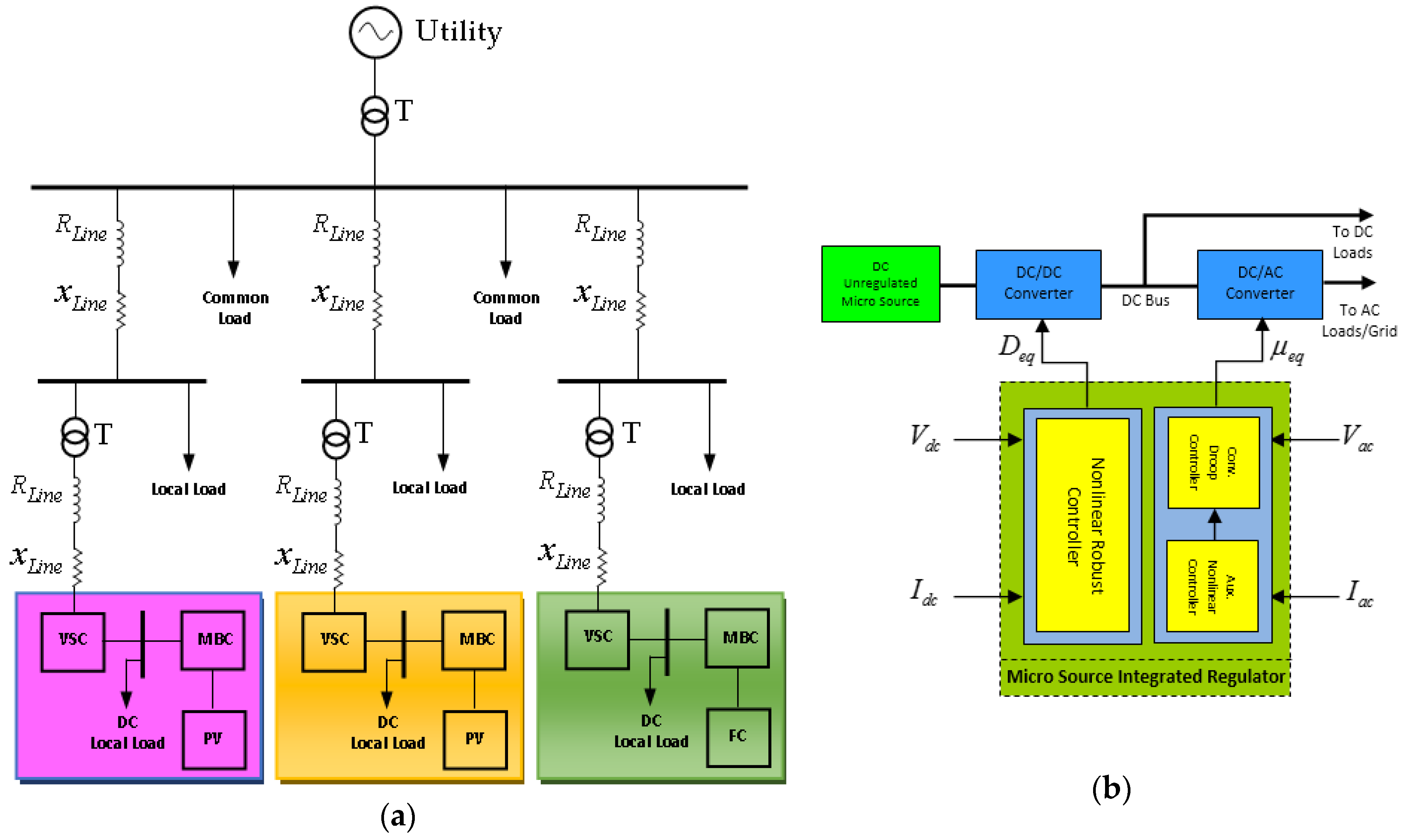
A hybrid AC/DC micro-grid includes three main sections: AC micro-grid, DC micro-grid and power electronic interfaces between AC side and input distributed sources.
Figure 1a shows general structure of a hybrid AC/DC micro-grid connected to the utility in which DC micro-grid is connected to the AC network through a middle converter. AC sources like wind turbines and small diesel generators and AC loads like conventional lights can be connected to AC micro-grid. On the other hand, DC power resources like photo voltaic panels, fuel cells and batteries can be connected to DC micro-grid through simple DC/DC converters. Moreover, a group of AC loads that operate with variable frequency like adjustable speed induction motors is better to be connected to DC micro-grid in optimal state [
7,
8,
9].
When AC micro-grid operates in island mode, control objectives include controlling frequency and voltage to increase dynamic and transient stabilities. While in island DC micro-grid, DC voltage or current should be controlled exactly so that power sharing among DC sources and DC loads is done perfectly. Finally, the simultaneous operation of AC and DC micro-grids can manage power flux between AC and DC networks correctly such that efficiency is optimized and stability is increased [
9,
10,
11,
12,
13].
Microgrids utilization requires a proper control schemes in order to control the power sharing as well as improve the small and large signal stabilities. Many researches have been performed on the dynamic stabilizing and power sharing control in microgrids. However, a few efforts have been made on the large signal stability and power flow control among AC and DC microsources in hybrid microgrids, mainly in the autonomous mode.
A proper method for power sharing imitated from conventional droop control of the governor system of the synchronous generators is used in AC microgrids [
14,
15,
16,
17]. To create the reference power when multi converters working together a frequency-droop characteristic is defined. Regarding to theory of droop control method the load power sharing is done based on related droop slope of each converter [
15]. Same as the above droop method the DC voltage droop approach is used for power flow control of DC microgrids. In this method power flow control is done via a virtual resistor [
14,
18,
19]. Also a supplement method by using adjacent converters is offered to increase accuracy of the power sharing and regulation of system voltage as well as reliability improvement via individual communication infrastructure [
20,
21,
22]. An autonomous power sharing method in multiple converters hybrid microgrids by establishing a superimposed frequency in the dc subgrid is presented in [
23].
Real-time control of hybrid microgrids including storage system and pulsed loads is presented in [
24]. In this work, the authors present a universal frequency and voltage control strategy for a hybrid AC/DC microgrid be composed of a synchronous generator, solar generation simulator and bidirectional converters.
A robust
control scheme for autonomous multidistributed microsources converter based microgrids is presented in [
25] which in that voltage and frequency set points of local controllers is specified by power management system as well as hierarchical droop based scheme. Also a robust
controller is established for tracking of set point and disturbance cancelation and also raising fault ride through capability and increasing performance in dynamic and transient disturbances as well as supplying nonlinear loads.
A finite time robust control strategy for regulation of voltage and frequency and control of active and reactive powers in autonomous microgrids is presented in [
26] which in that the response of the controller is very fast when various inverters are operated in complex conditions. The major advantages of the proposed control scheme are being robust against unmodeled dynamics, parametric uncertainty, loads changing and large variation of work point.
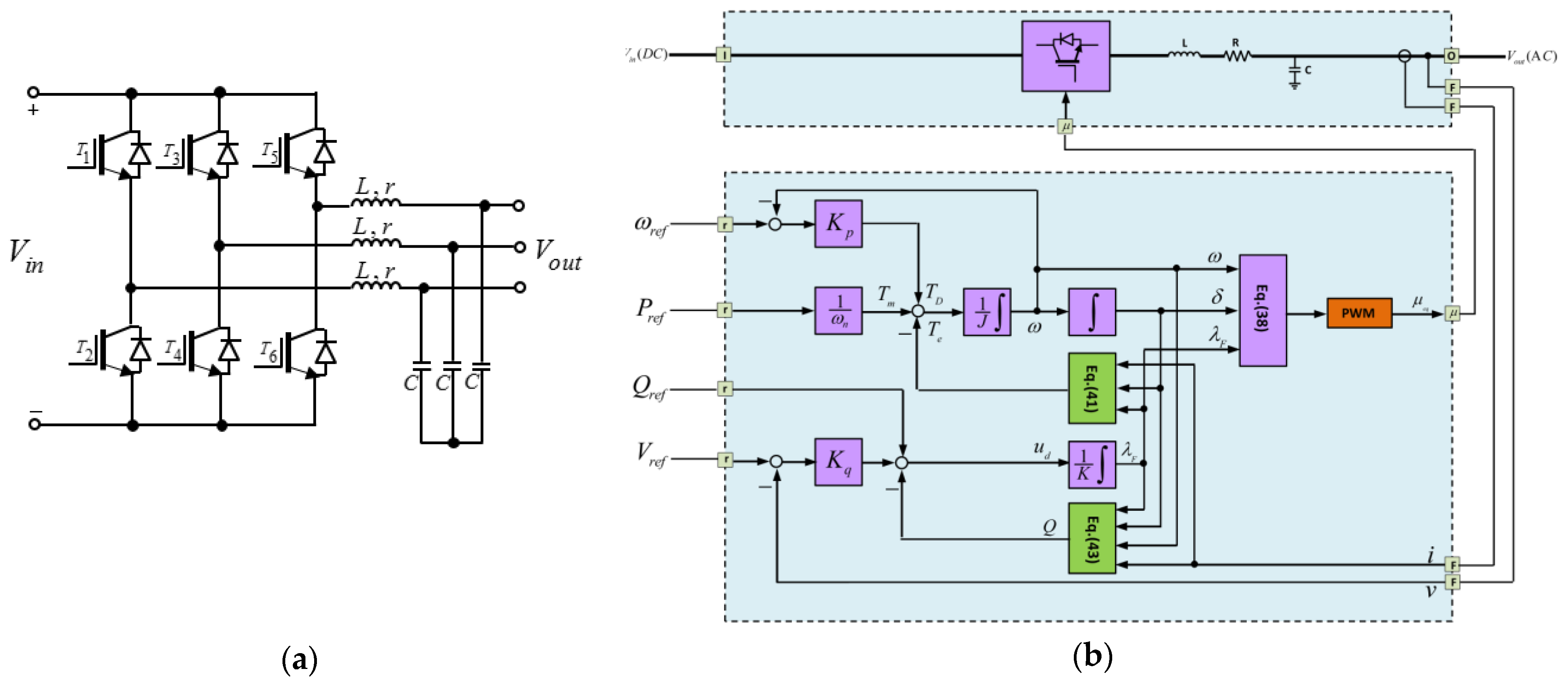
Considering the discussion above, in this paper a hybrid AC/DC micro-grid is controlled such that it can provide the stability of the micro-grid when a large signal disturbance occurs like short circuit in point of common coupling (PCC) and changing operating mode from grid connected mode to islanding mode. For this purpose, an integrated controller is used to control DC and AC parts of the micro-grid as shown in
Figure 1b.
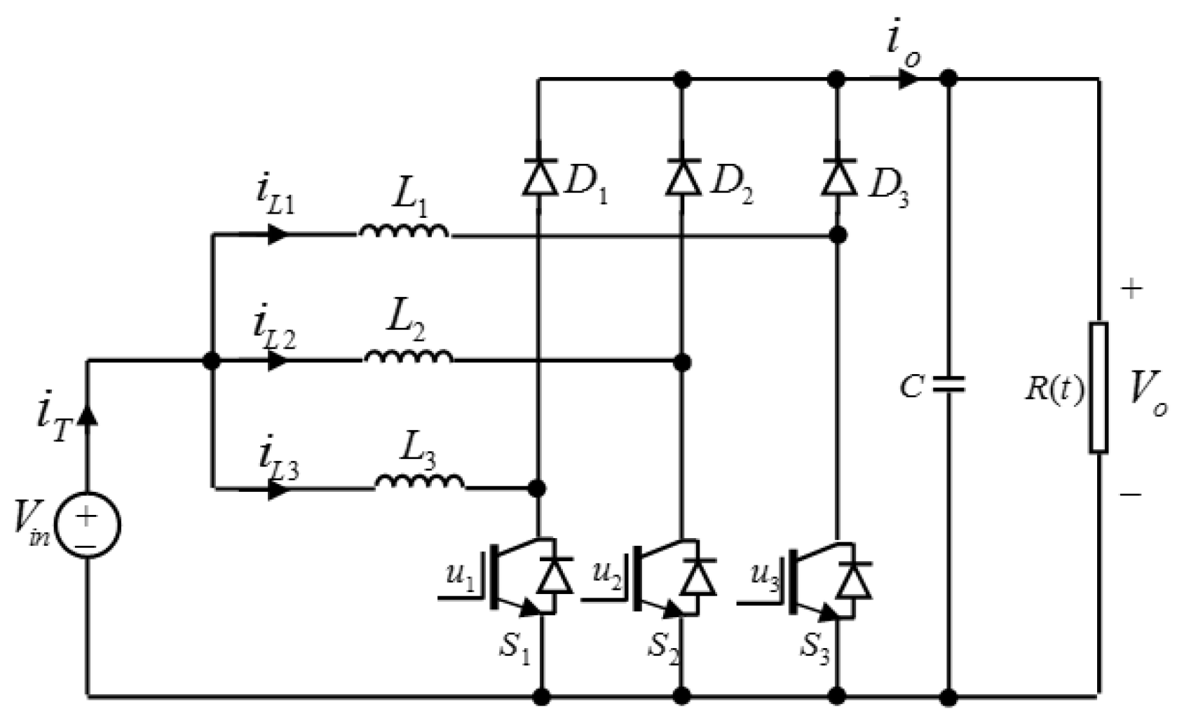
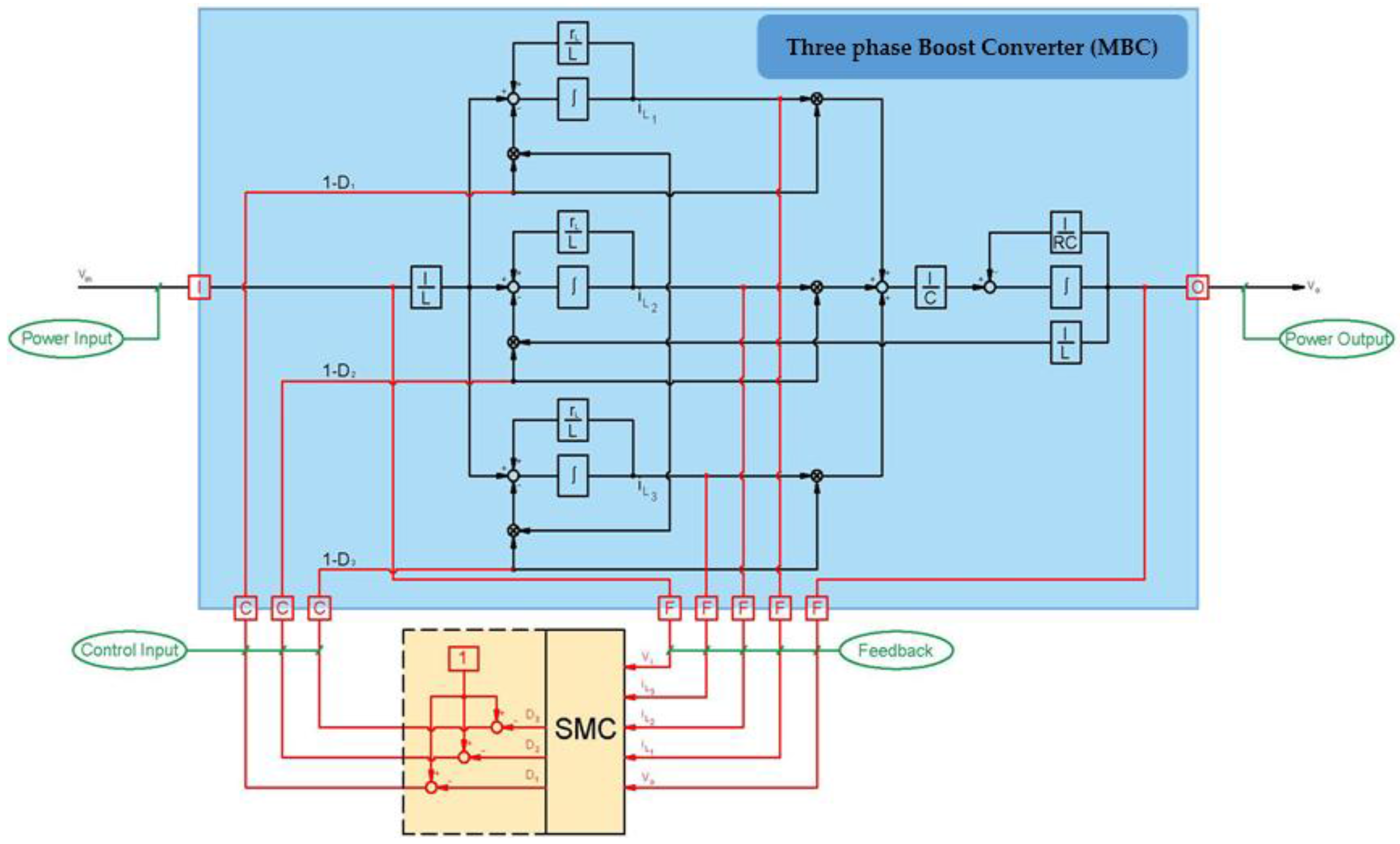
According to this figure, each unregulated DC source is connected to the AC network through two cascade converters. Input converter is a Multiphase Boost Converter (MBC) which increases DC voltage amplitude of the micro source and stabilizes output DC voltage using a robust nonlinear controller when variations of the load resistance are not known. Output converter is a DC to AC voltage source converter (VSC) which tunes amplitude, frequency and phase of the output AC voltage such that not only power can be shared in steady state but also the stability of the micro-grid when large disturbances occur is guaranteed. For these purposes, a conventional droop control with a supplementary controller is proposed.
The rest of this paper is organized as follows:
Section 2 which is comprised of three subsections presents MBC and input micro sources models, how the proposed nonlinear controller is designed and its stability is proved. In
Section 3 which is comprised of three subsections, VSC of the AC section is modeled and the proposed controller is designed and its stability is proved. Performance of the controllers under different disturbances is simulated numerically and the results are given in
Section 4.
Section 5 and presents concludes and appendix of the paper.
3. Design of a Robust Controller in order to Improve Performance of AC Section
Many researches have been conducted for steady state operation and preserving dynamic stability of AC micro grids. In most studies, droop control method is presented as an effective method [
14,
15,
16,
17,
18]. In conventional droop control, small signal stability is provided by adjusting frequency and voltage droop coefficients and enhancing power sharing among micro-grids [
15,
16]. If droop coefficients in island mode are increased, power sharing correctness is enhanced at the expense of reducing accuracy of frequency and voltage regulation. Larger droop coefficients create negative effect on system stability as well as limitations on operational performance. In other words, there is a trade-off among power distribution, power quality, transient response and system stability. However, in many disturbances especially large signal disturbances, the inefficiency of the droop control method is obvious.
3.1. Structure of the Proposed Controller in AC Section
In order to solve the mentioned issues, an inclusive control structure is proposed. Each of the control necessities of AC section of a micro-grid in steady and transient states are presented in this structure. This structure includes power, frequency and angle control loops and benefits from all of the advantages of them concurrently. Invariant frequency utilization and accrued power distributing can be achieved using frequency droop while transient stability is provided by the proposed supplement controller which is a nonlinear controller. Other advantages of proposed control structure will be described later.
3.2. Modeling AC Section of the Micro-Grid
In this paper, a general framework is used to design and establish a controller for both operation modes. To this end, first a model is proposed to improve dynamic of the inertia less converters based on virtual rotor idea by imitating inertia of the rotor and damping coefficient of the synchronous generators. This model which is described completely in [
45,
46,
47] and introduced as a virtual synchronous machine (VISMA), models a power electronic converter the same as
Figure 6a, similar to a synchronous generator.
First idea of this model is to imitate back induction voltage law and dynamic of rotor of the synchronous generator with momentum
and viscose friction
. The advantages of imitating rotor dynamic are improving dynamic response of the converter and creating a proper control structure to exploit all of the operating conditions. In this model, the virtual rotor is a frequency dynamic controller, a role that does not exist in conventional voltage/current controller. Virtual friction (
m) damps frequency oscillations. Summary of the modeling based on VISMA using equation of the voltage generated by conventional synchronous generator is as follows [
45]:
where
shows a balanced three phase voltage,
is excitation flux,
and
are virtual angle and angular speed. Frequency dynamic can be presented as follows:
In (39),
is damping ratio,
and
are virtual mechanical and electromagnetic torques.
is calculated based on stored energy in magnetic field of the machine (
) as follows:
By defining
in terms of current and flux of the armature and exciter (40) is obtained as follows:
In addition, active and reactive powers can be described as follows:
In this model state variables include current of inductors (), voltage of capacitor (), virtual angle and angular speed ( and ). Also mechanical torque () and excitation flux () are control inputs.
For proper operation of converter based on this model, a controller is required which can follow proper values of active and reactive powers as well as increase system stability by generating appropriate torque and flux signals.
Same as synchronous generators, in VISMA frequency droop is used to improve power sharing and frequency restoration. In this modeling, the frequency droop is defined as follows:
Similarly, voltage droop can be defined as follows:
Considering the above descriptions, the model of AC converters in this paper can be presented as
Figure 6b [
45].
As can be seen in
Figure 6b, this model has a real power control loop and is able to share power variations with other similar converters and same size synchronous generators automatically due to internal frequency droop mechanism. It can also be said that due to absence of mechanical equipment, structure of this loop is very simple.
Frequency droop loop (with gain
) has a time constant of
. Thus, if
is selected as a design parameter,
can be obtained as follows:
Lower loop is related to reactive power control. Error between reference voltage and output voltage is multiplied by the droop coefficient
and is summed up with error between output reactive power (Equation (43)) and its reference value finally the result (
) is obtained as excitation flux after passing integrator with gain
. Voltage droop loop (with gain
) has a time constant approximately equal to
. Thus, if
is selected as a design parameter,
can be obtained as follows:
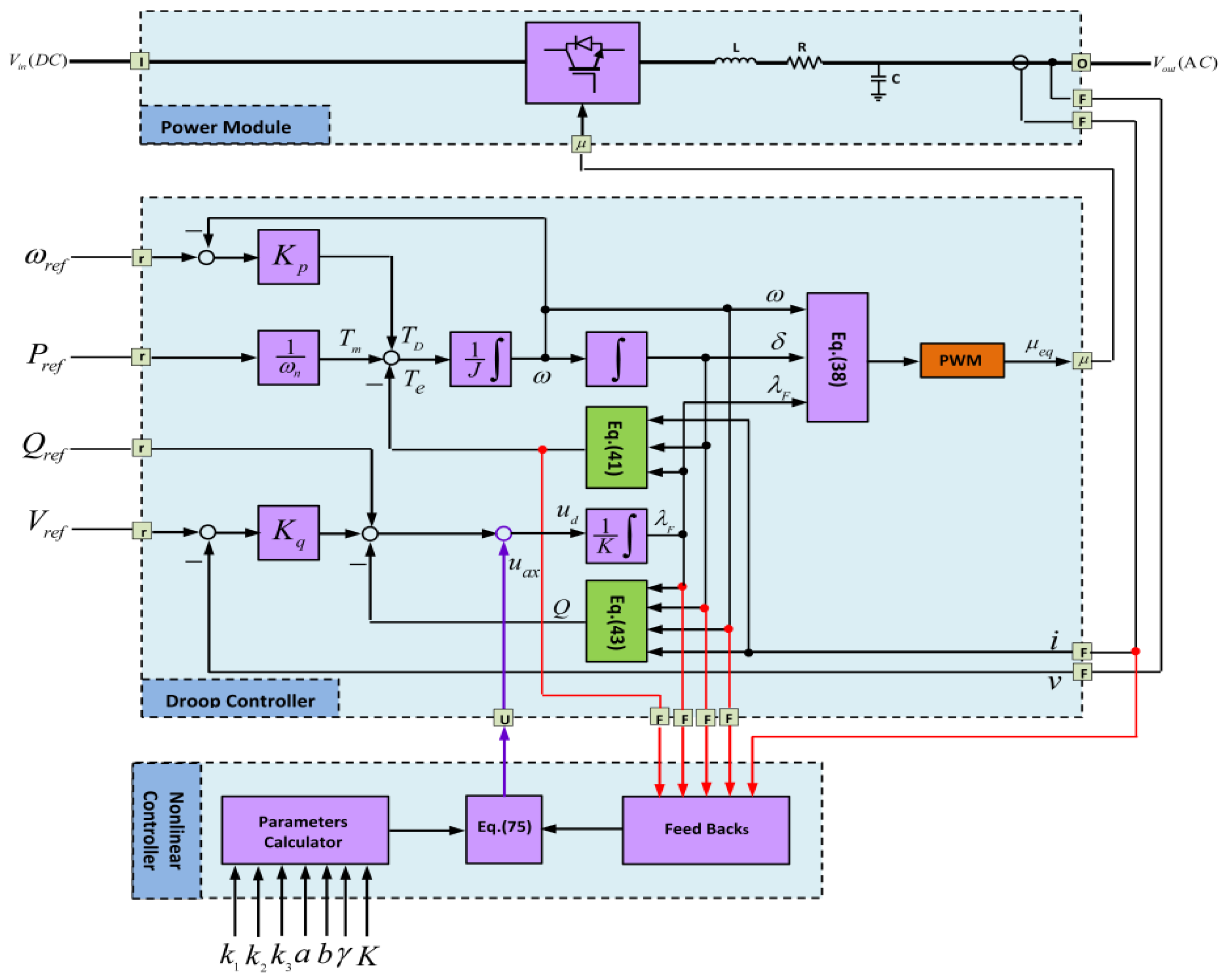
3.3. Adaptive-Nonlinear Supplement Control
Since the model based on VISMA performs well in steady and dynamic states and resolves operational requirements, but it does not perform well in large signal disturbances such that the system under this model becomes unstable. Thus, in this paper, a supplement nonlinear controller is added to the existing droop controller to guarantee transient stability of the converter (and micro-grid). In fact, when a large disturbance occurs, the proposed nonlinear controller injects an additional signal to the VISMA to stabilize the system by changing amplitude of the virtual flux. In steady state, this controller is in idle phase. Advantages of the proposed controller include:
Universal and flexible structure for all of the operation modes and not requiring to change strategy after islanding detection.
As compared to other controllers, where delay in islanding detection reduces stability margin, this problem is resolved inherently in the proposed controller.
Possibility to create a soft and seamless path from grid connected mode to islanding mode.
Frequency droop control loop of this controller is a useful tool for power sharing between micro sources.
This controller only uses local signals, thus no communication infrastructure is required.
Figure 7 shows the structure of the supplementary nonlinear controller. According to this figure, it is obvious that the supplement controller adds an extra command (
) to the VISMA model which aims to improve stability.
Finally, it can be said that stable performance of the micro-grid during a harsh transient like unplanned islanding, short circuit and sudden changes in power consumption is satisfied using this controller.
In the proposed controller, power angle (
), frequency (
) and virtual torque (
) are state variables. Frequency dynamic is controlled by frequency droop control and virtual rotor as shown in
Figure 7. Accordingly, dynamics of angle and frequency can be described as follows.
In (48) and (49),
and
represent frequency and angle deviations from their work point. Dynamic of the torque equation is calculated using the following equation:
Derivative of flux is determined using dynamic of the voltage loop of
Figure 7. In order to design this controller, following state space model is used:
In this equation,
,
,
,
and:
is the main input of virtual flux generator or input of the integrator of the reactive power control loop as shown in
Figure 7 and
is the supplementary signal provided by proposed supplementary nonlinear controller. Term
is introduced to consider system uncertainty which can be caused by disturbances, variations in model parameters, inaccurate measurements, etc. This uncertainty is usually estimated by adaptive techniques to be robust against mentioned uncertainties. Purpose of the controller is to minimize error between desired reference value
and its real value
. Error is defined as follows:
Below Lyapunov function is defined to design this controller:
Derivative of this equation is equal to:
In order to stabilize state
, derivative of
should be negative definite. Thus:
According to (57) there is no guarantee that is negative definite. In next steps, becomes negative by proper selection of and . In order to stabilize frequency dynamic, is selected according to Lyapunov function.
Derivative of (59) is equal to:
where
. Using (51) and (56), we have:
Thus
is simplified as follows:
In order to guarantee stability of the system, the final Lyapunov function is considered as:
In which
is an estimate of uncertainty function
and
is gain of the adaptive rule. Dynamics of
can be written as follows using associated equations:
Value of
can be found as follows using (51), (56) and (62):
Finally,
is obtained as follows
Now, if adaptation rule is selected as:
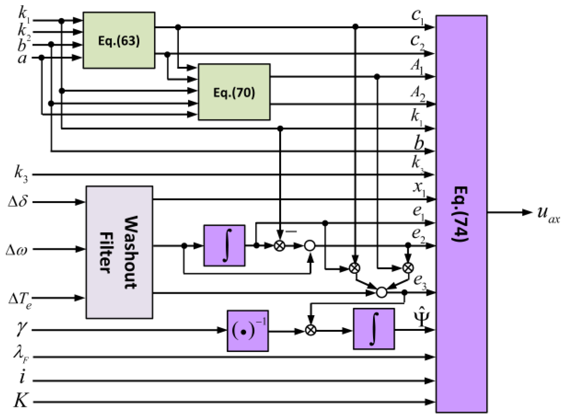
Accordingly, if control input is selected as follows:
By displacing (73) in (74), Lyapunov function is described as below:
Therefore, the stability of the system is guaranteed when using control signal in (74). Control parameters of this controller are
. Performance of the system depends on these coefficients and designer has a high degree of freedom to find the best combination of these constants to obtain the maximum trade-off between performance objectives of the system. Realization of proposed controller for AC side of the microgrid is shown in
Figure 8.
4. Simulation Results and Evaluation of the Proposed Controller
Different simulations are performed in MATLAB/SIMULINK (MathWorks Inc., Natick, MA, USA) to study dynamic and static performances of the proposed controller topologies. These scenarios include:
Unspecified changes in the current taken from DC bus of each micro-sources
Changing electrical characteristic of the micro- sources
Unplanned islanding
Loading in islanding mode
Short circuit in PCC
The simulated system shown in
Figure 9 has three micro-generators that provide their local load in parallel and supply other common loads in PCC. Parameters of the micro-generators and the related network are given in
Table A1. Input voltage of inverters is fully stabilized using the proposed control topology of related boost converter. Input sources are DC and include fuel cell and photo voltaic panel. Dynamic characteristic of these sources are completely considered in the simulations.
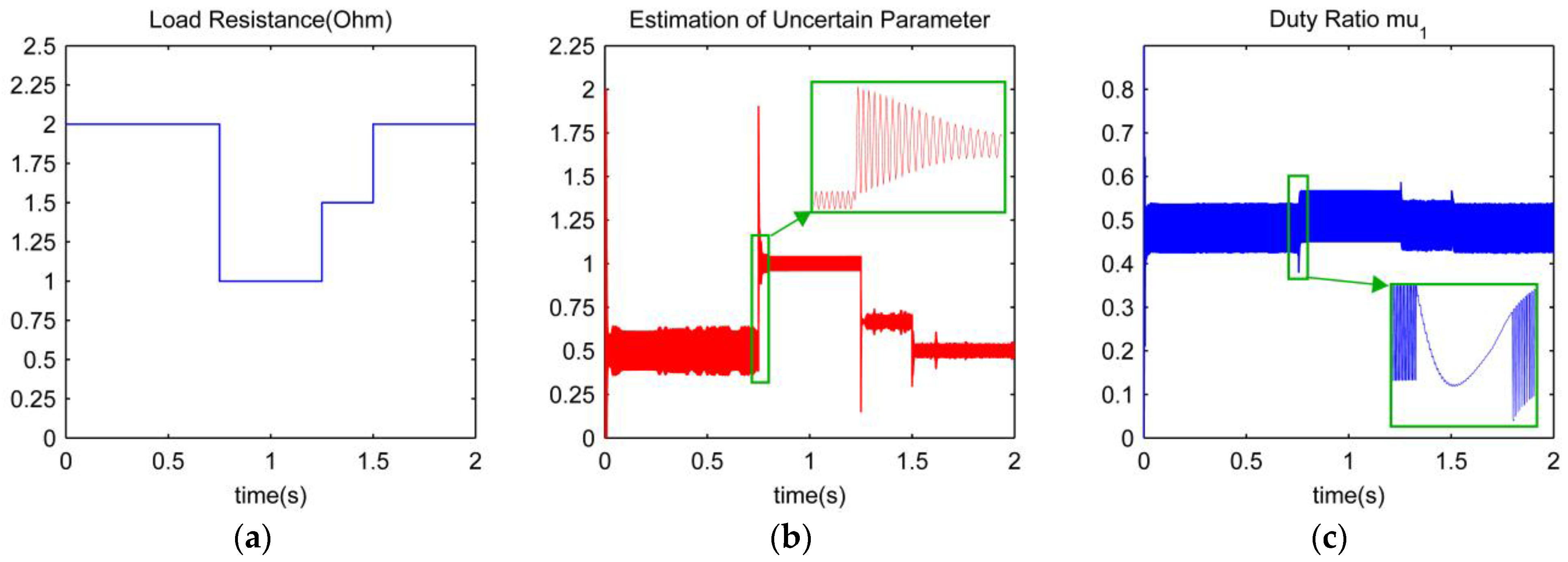
4.1. Unspecified Changes in the Current Taken from DC Bus
In this scenario, resistance of the connected load to output of the boost converter varies as steps with different amplitudes and purpose of the controller is to stabilize voltage of DC bus on the reference value. For this purpose, according to
Figure 10a, the resistance of the load is changed as steps with different amplitudes. First, the identification section of the proposed controller estimates the load conductance at each moment rapidly according to
Figure 10b, such that error of this estimate tends towards zero. Result of this fast estimate at first stage is to change duty cycle of switches according to
Figure 10c. Chattering phenomenon which is one of the characteristics of sliding mode controller is seen clearly in this figure.
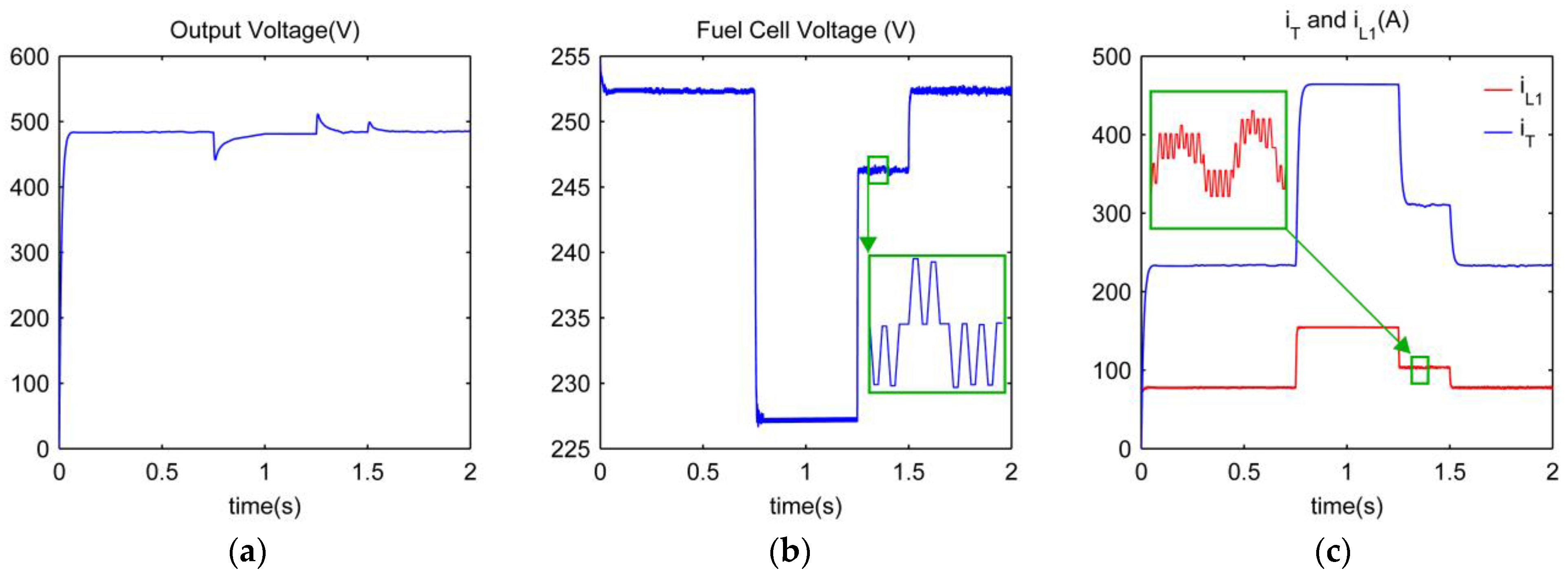
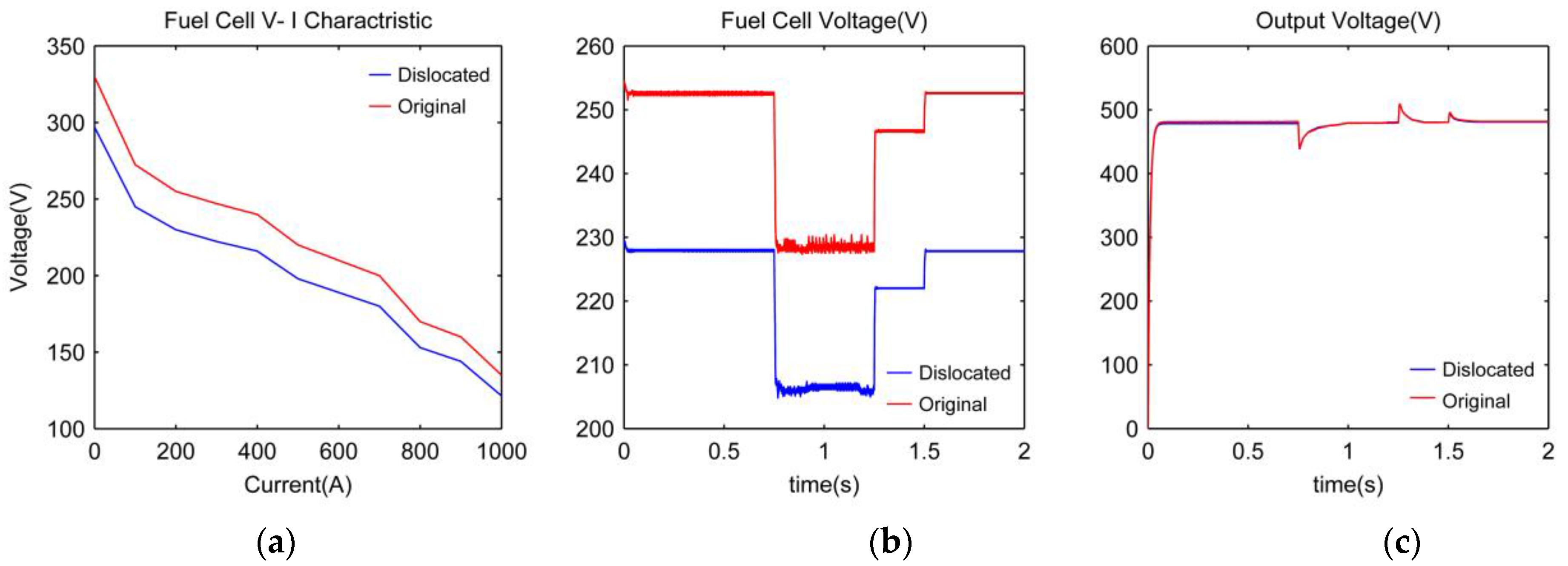
Figure 11b shows the voltage of the fuel cell while changing the load. According to this figure, due to dynamic of the V-I characteristic of cells, severe variation is observed in generated voltage of the fuel cell. Although voltage of the fuel cell varies significantly, but according to
Figure 11a in the presence of the proposed controller, the output voltage of the converter is stabilized on the defined value (480 V). This figure shows the high proficiency of the proposed controller.
Figure 11c shows current of different phases as well as current taken from fuel cell. According to this figure, current sharing between different phases is done very well and one-third of the total current has passed through each phase. One of the main advantages of multiphase boost converter which is eliminating ripple of the current taken from the fuel cell can be seen in this figure. This issue is very important as increases the lifetime of the cell.
4.2. Changing Electric Characteristic of the Micro-Source
Since the electric characteristic of micro-sources are uncertain due to changes in environmental conditions, robustness of the proposed converter against this uncertainty should be evaluated. For this purpose, the dynamic characteristic of the cell is varied 10% according to
Figure 12a and the previous scenario, changing resistance subsequently, is performed again. In the presence of such uncertainty, although fuel cell as input of the converter has changed as shown in
Figure 12b, but in the presence of the proposed controller, the system is able to adjust output voltage as in
Figure 12c. Finally, it can be said that this scenario shows high performances as well as high robustness of the proposed controller in the presence of uncertainty in the load and source characteristics which results in a fully stable DC bus in the network and possibility of AC voltage regulation in hybrid micro grid consequently. Similar results and analysis are obtained for input of the photo voltaic panels, but they are not presented in this paper due to limited number of pages.
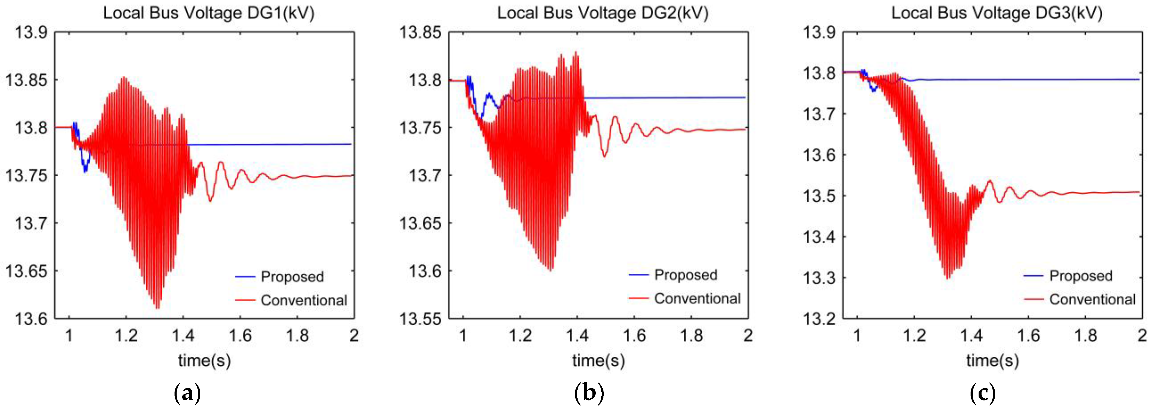
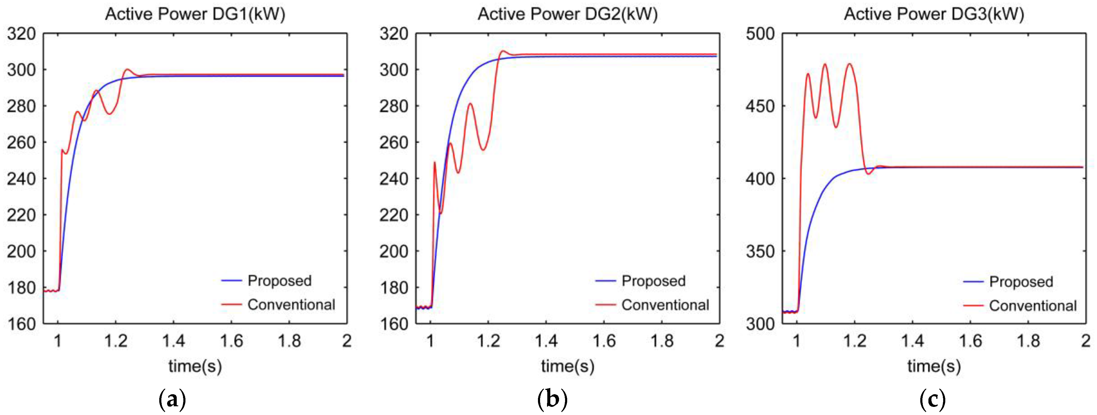
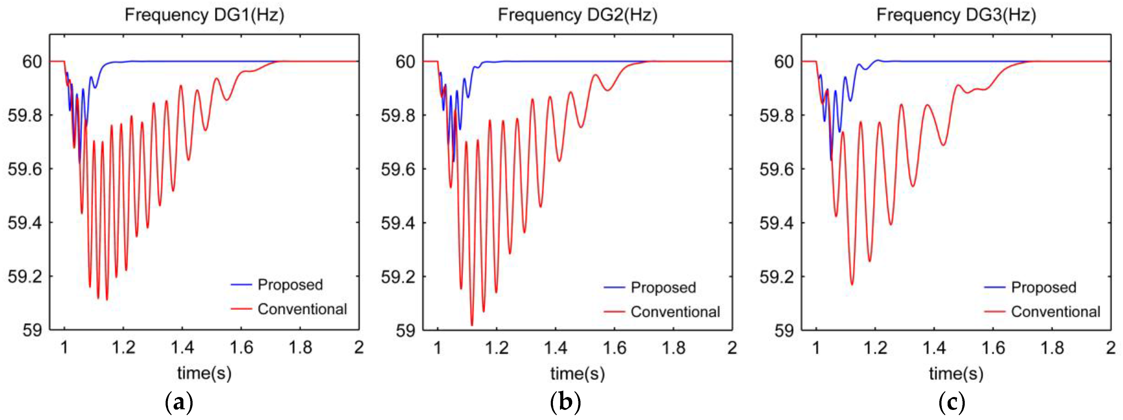
4.3. Unplanned Islanding
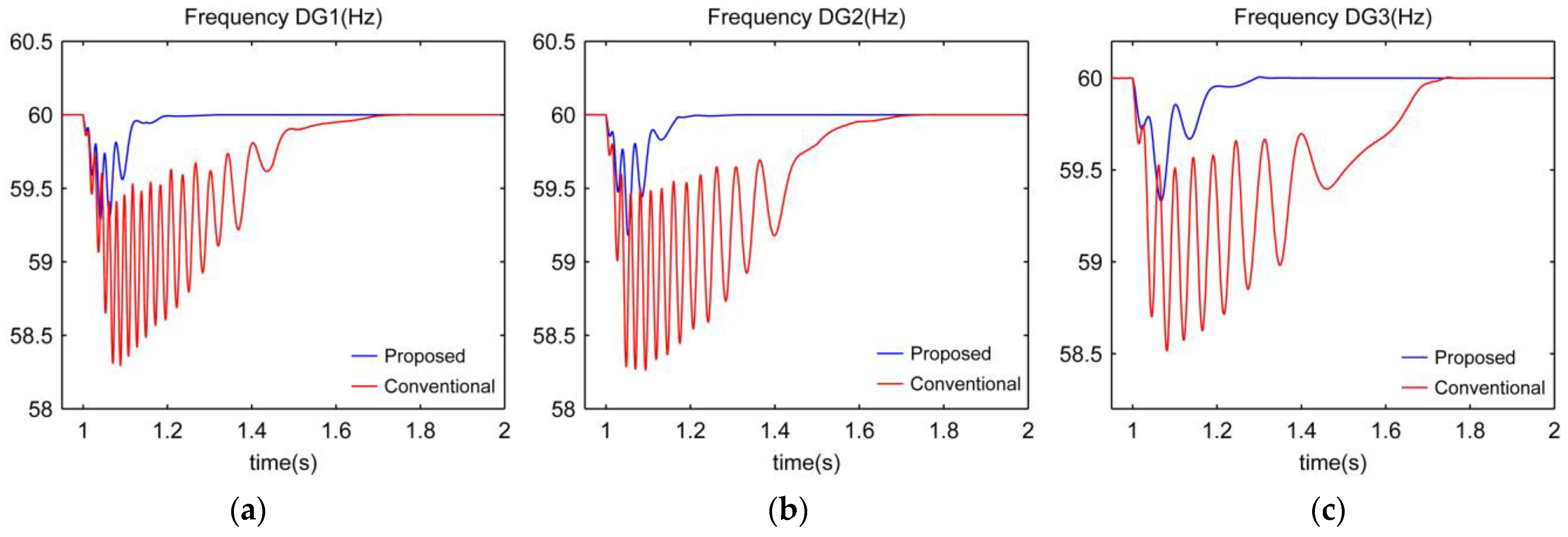
It is assumed that DG units are connected in parallel in a period of time and all of them are connected to the utility. At t = 1 s, islanding occurs and micro-grid is separated from the utility. Islanding is a large disturbance from controller’s point of view.
Figure 13,
Figure 14 and
Figure 15 show variations of power, voltage and frequency during transition from grid connected mode to autonomous mode.
Since in the studied system, it is assumed that one portion of the load power is provided by the utility, output power of DGs increases to provide local load. This scenario is one of the most difficult states which might occur while operating a micro-grid.
Results show a soft transition with minimum overshoot in variables as compared to their steady state, such that average damping time of frequency variations is about 200 ms and maximum undershoot is 0.7 Hz. Voltage of DG units are shown in
Figure 14. Based on this figure the damping time and maximum under/overshoot of the DG’s output voltages by using proposed controller are very negligible in compare with conventional droop controller.
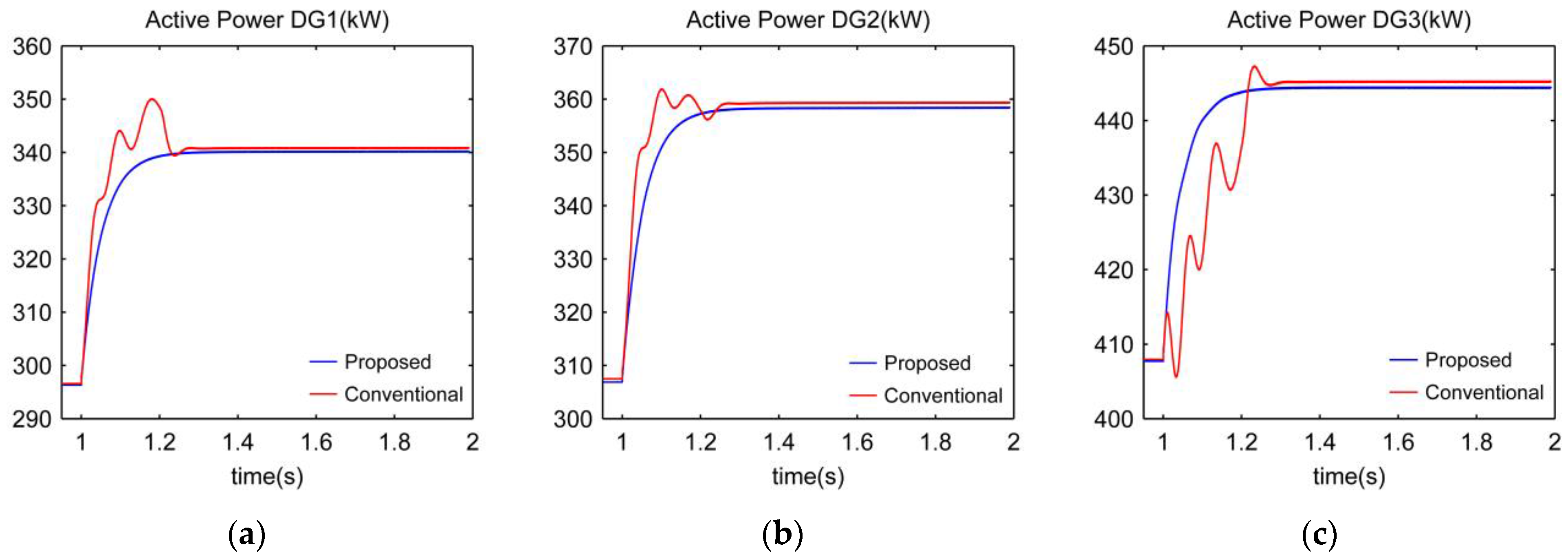
Power sharing in the presence of proposed nonlinear controller is shown in
Figure 15 which has occurred with softer transitions.
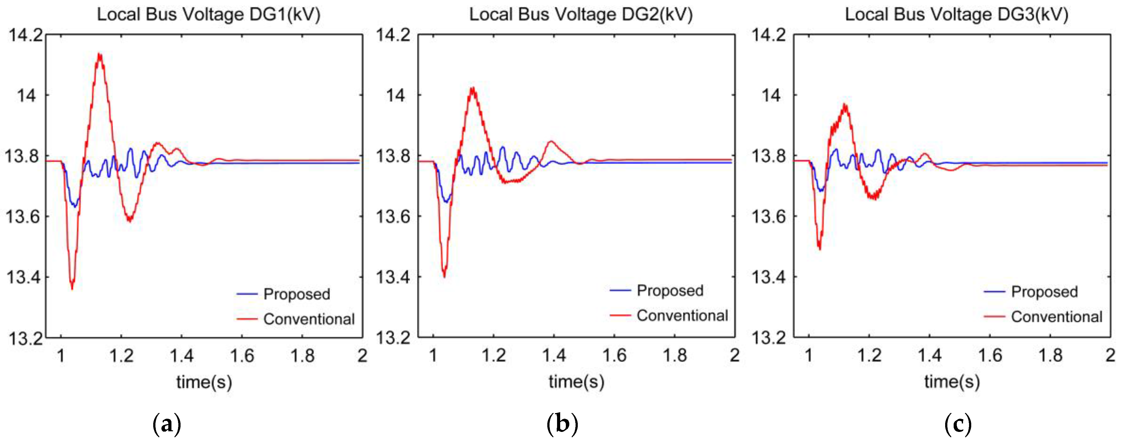
4.4. Loading in Islanding Mode
In this case, it is assumed that micro-grid operates in islanding mode and at t = 1 s, a 125 kW nonlinear load in PCC is connected to it. Simulation results are given in
Figure 16,
Figure 17 and
Figure 18.
According to these results, when applying a nonlinear load, the proposed controller can reconfigure the network and accelerate damping of variables oscillations such that frequency restoration is performed in less than 150 ms and maximum frequency drop is 0.35 Hz.
Based on
Figure 17 the damping time and maximum under/overshoot of the DG’s output voltages by using proposed controller are very negligible in compare with conventional controller.
It can also be seen that power sharing between micro-sources in the presence of the proposed controller is very soft while in the presence of conventional drop control, overshoot is observed.
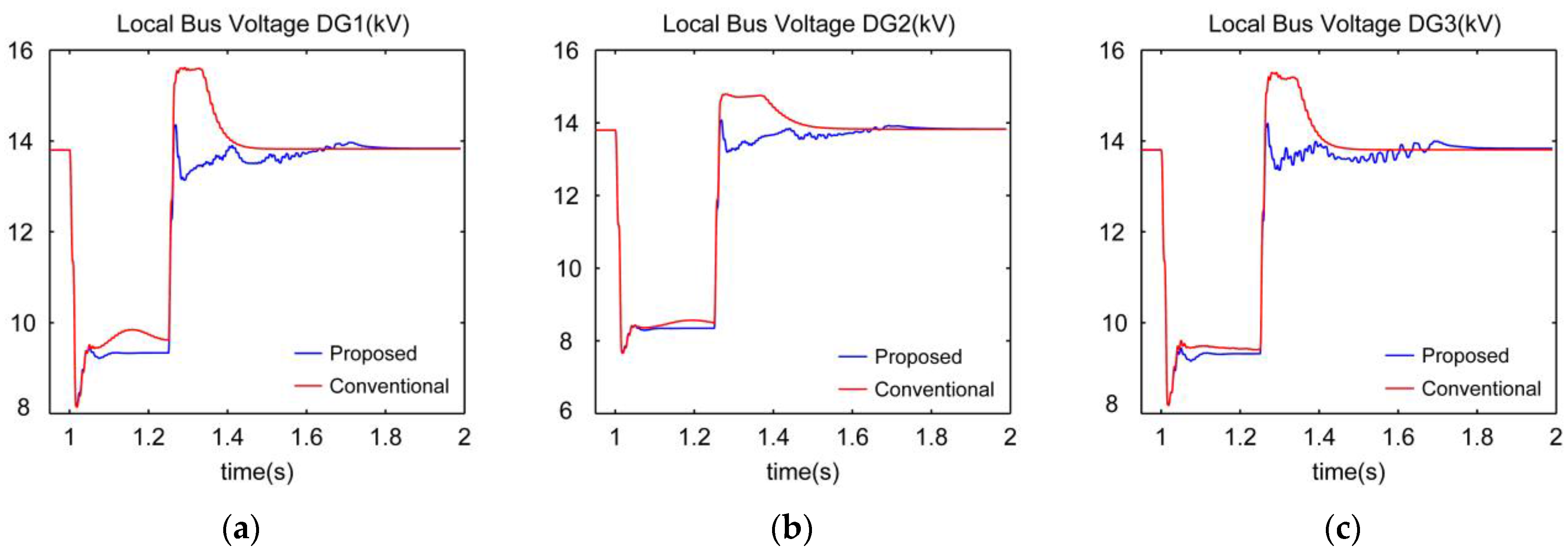
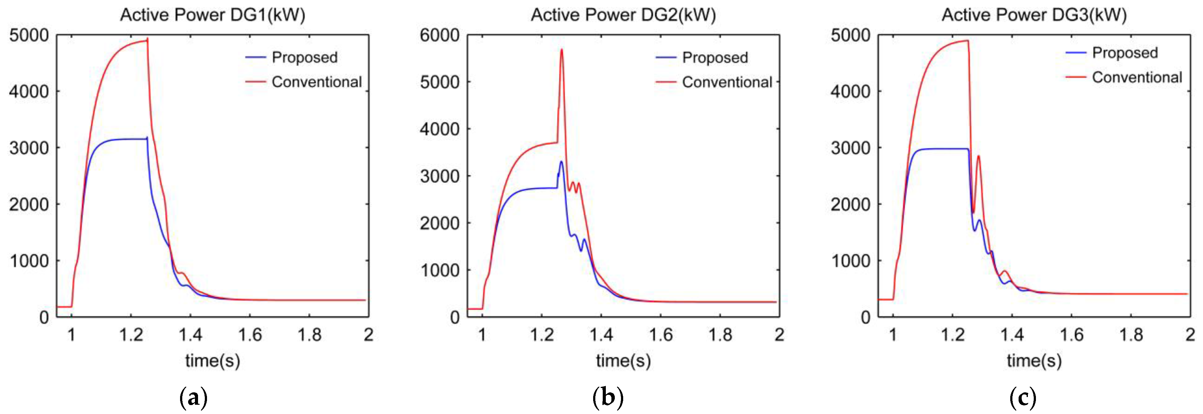
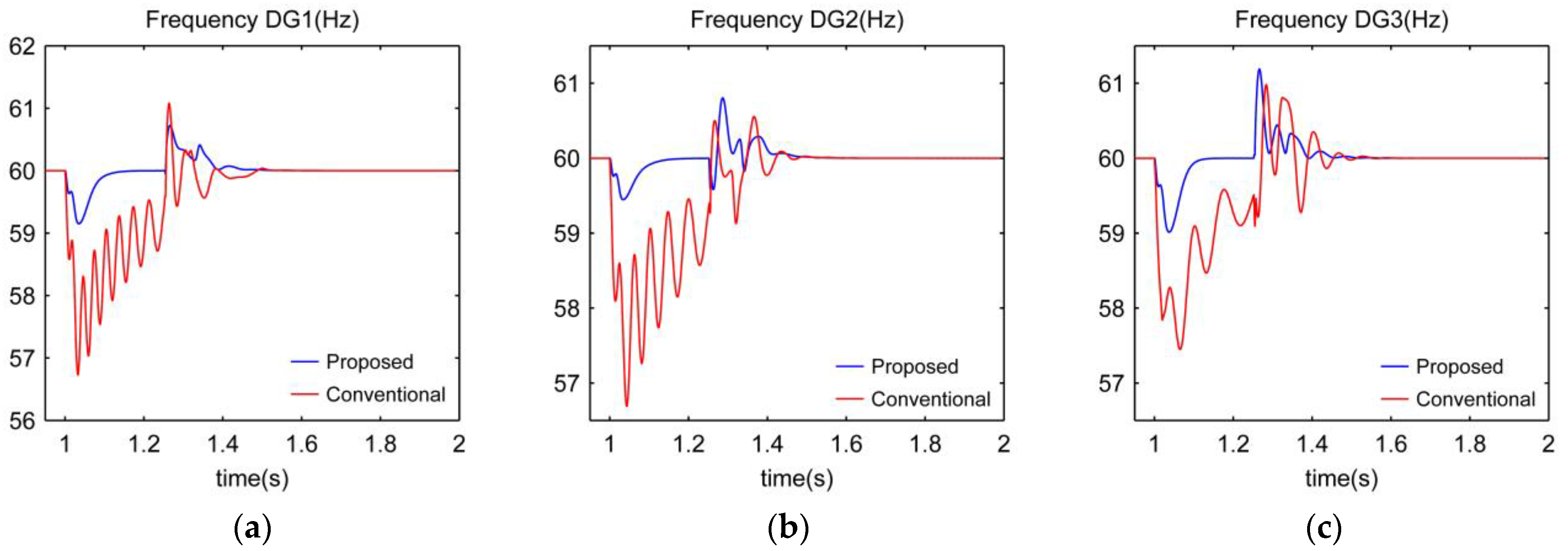
4.5. Short Circuit in PCC
At t = 1 s, a three phase symmetric short circuit fault occurs in PCC, because of which after 250 ms, fault is cleared and islanding mode has occurred. According to the results shown in
Figure 19,
Figure 20 and
Figure 21, it can be seen that while fault is established, frequency drops 1 Hz and when fault is resolved, 1.5 Hz overshoot is created and after 300 ms, frequency is restored very well.
As shown in
Figure 20 while fault persists, the voltage in PCC is zero and has the minimum possible value at the output of micro-sources. After clearing fault, when the proposed controller is available, voltage is restored with appropriate overshoot and settling time.
As shown in
Figure 21, power distribution during short circuit is better in the presence of the proposed controller as compared to conventional controller. In the presence of the nonlinear controller, power injection to fault point is limited.


