Review

Lithium-Sulfur Battery Technology Readiness and Applications—A Review

1
Advanced Vehicle Engineering Centre, Cranfield University, Bedfordshire MK43 0AL, UK
2
OXIS Energy, Culham Science Centre, Abingdon, Oxfordshire OX14 3DB, UK
*
Author to whom correspondence should be addressed.
Energies 2017, 10(12), 1937; https://doi.org/10.3390/en10121937
Submission received: 29 September 2017 / Revised: 12 November 2017 / Accepted: 16 November 2017 / Published: 23 November 2017
(This article belongs to the Section D: Energy Storage and Application)

Abstract

:
Lithium Sulfur (Li-S) battery is generally considered as a promising technology where high energy density is required at different applications. Over the past decade, there has been an ever increasing volume of Li-S academic research spanning materials development, fundamental understanding and modelling, and application-based control algorithm development. In this study, the Li-S battery technology, its advantages and limitations from the fundamental perspective are firstly discussed. In the second part of this study, state-of-the-art Li-S cell modelling and state estimation techniques are reviewed with a focus on practical applications. The existing studies on Li-S cell equivalent-circuit-network modelling and state estimation techniques are then discussed. A number of challenges in control of Li-S battery are also explained such as the flat open-circuit-voltage curve and high sensitivity of Li-S cell’s behavior to temperature variation. In the last part of this study, current and future applications of Li-S battery are mentioned.

1. Introduction

Various new energy storage technologies are under development such as batteries, fuel cells, ultra-capacitors, flywheels, etc. One such new energy storage technology is lithium-sulfur (Li-S) battery. Li-S is generally considered the post lithium-ion (Li-ion) chemistry of choice for high energy density applications. Over the past decade, there has been an ever increasing volume of Li-S academic research spanning materials development [1,2,3,4], fundamental understanding [5,6,7] and modelling [8,9], and application-based control algorithm development [10,11]. In addition, the industrial interest in developing Li-S technology has increased from two to three dedicated research companies in 2007 [12,13] to almost every global cell developer investing in their in-house Li-S research capability by 2017 [14,15,16]. This boom in interest in Li-S is driven by the huge potential advantages it brings over Li-ion. In comparison with the existing Li-ion technologies, Li-S cell has higher specific energy, predicted to be 2–3 times higher than the best performing li-ion equivalents [17,18], improved safety, and—when productionized—a lower unit cost due to the wide availability of sulfur [19,20]. Consequently, Li-S cell development and its applications are receiving serious research attention. The technology has not been commercialized yet because it suffers from limitations such as poor instantaneous power capabilities, high self-discharge and short cycle life, particularly in the presence of high discharge currents [21].
There are, however, efforts to improve Li-S cell chemistry and construction to mitigate these problems. Much of today’s research into Li-S batteries concerns the development and understanding of materials, construction and the fundamental scientific understanding of cell behavior [22,23,24,25,26,27,28,29,30,31]. The importance of this should not be questioned, but lithium-sulfur is beginning to reach maturity, and there is a need to develop the engineering science and techniques necessary for deployment in practical applications. In particular, there is a need to devise algorithms that can be used to estimate state-of-charge (SoC) and state-of-health (SoH) measures. Electrochemistry is of course key here, but it is equally vital to draw from other disciplines: in particular, control theory has much to offer, particularly in respect to state estimation.
In this study, the Li-S battery technology, its advantages and limitations are firstly discussed. The research studies in this area are mainly focused on development of materials and mechanisms to improve the current limitations of this technology. The theories of electrochemistry are used in such studies for a better understanding of a Li-S cell’s behavior. In the second part of this study, state-of-the-art Li-S cell modelling and state estimation techniques are reviewed with a focus on practical applications. Li-S cell equivalent-circuit-network (ECN) modelling and state estimation techniques in the literature are discussed in this section. In the last part of this study, current and future applications of Li-S battery are mentioned and discussed.

2. Li-S Battery Technology: Advantages and Limitations

The lithium-sulfur battery system is an electrochemical system with the potential for extremely high gravimetric energy, however it is yet to be commercialized. The full reduction reaction involves the transfer of 16 electrons per S 8 molecule, which leads to the theoretical capacity of 1675 mAh . g ( s ) 1 and theoretical energy density of 2500 Wh . kg ( s ) 1 . The working mechanism is complex and still under debate, however the working principle can be summarized as follows. In a fully charged state, a Li-S cell consists of a cathode usually containing sulfur, a carbon-based material and a binder. The anode is lithium metal and is separated from the cathode by a polymer separator and an organic-solvent based electrolyte. During operation (discharge), solid sulfur from the cathode dissolves into the electrolyte, forming S 8 ( l ) . Liquid S 8 is then electrochemically reduced at the cathode to form intermediate products, so called lithium polysulfide species ( Li 2 S x ) with an accompanying oxidation of Li metal to Li + ions at the anode. The polysulfides species ( Li 2 S x 2 < x ≤ 8) are soluble in the liquid electrolyte and diffuse out from the cathode to the electrolyte/separator side. When the discharge proceeds, the length of the polysulfide chain is getting reduced, which in turns affects the viscosity, mobility and solubility of Li 2 S x compounds. At the end of discharge, S 8 is fully reduced to S 2 ( Li 2 S ) and the anode is fully stripped of Li metal. This process is demonstrated schematically in Figure 1. During charge, the reverse reactions occur, with Li + ions depositing at the anode as Li metal and low-order polysulfides oxidizing from S 2 up to S 8 2 and eventually S 8 ( s ) .

2.1. Advantages of Lithium-Sulfur System

The key advantage/driver of Li-S battery technology is the high theoretical and practical energy density that can be achieved by combining a lithium metal anode with a sulfur cathode. The theoretical specific capacity of a Li-S cell is 1675 mAh . g 1 or 2500 Wh . kg 1 [17,32] which comes from the 16 electron reduction of a S 8 molecule at the cathode, shown below.
S 8 + 16 e + 16 Li + 8 Li 2 S
In practical terms, one can assume that the practical achievable capacity of a battery, taking into consideration the additional mass required by cell ancillaries (pouch material, tabs, separator, excess of active material) could reach 25–33% of the theoretical value. In the case of Li-S, the practical achievable gravimetric energy is often stated to be ~600 Wh . kg 1 [33]. Although much lower than the theoretical, this value is still 2–3 times higher than state-of-the-art Li-ion, which after 30 years of development, has reached approximately 280 Wh . kg 1 [34]. This allows for either more energy for an equivalent battery pack, or a lighter pack with equivalent energy delivered. As Li-ion progress is levelling out at ~280 Wh . kg 1 at cell level, Li-S is a very attractive alternative with the potential to more than double the energy capability of an equivalent Li-ion pack. Applications where weight is a critical parameter are discussed in more detail in Section 4.
The existing prototype cells are still far from the target (~600 Wh . kg 1 ) however, cell manufacturers are expecting to get it in the near future. For example, in Table 1, specifications of a 21 Ah prototype Li-S cell, developed by OXIS Energy Ltd. Abingdon, UK, are presented [12].
In addition to the energy capabilities of Li-S cells, another key advantage is the raw materials that go into the cell. Sulfur itself is cheap, abundant and non-toxic and presents a more environmentally friendly option than the heavy-metal based Li-ion cathodes in terms of both cost and safety [19,20]. It is difficult at this stage to quantify the cost reduction compared with Li-ion when Li-S are produced at scale, however it can be assumed that the cell cost will be lower (around $100 per kWh).
Aside from the materials chemistry advantages, at a user-level, Li-S cells are able to be discharged to 0% SoC and do not require top-up charging when in storage. That is, they can be left ‘on the shelf’ in a discharged state for indefinite storage periods without significant capacity degradation. This presents a significant advantage over Li-ion cells which require regular recharging and storage at a specific SoC, usually around 40%, to prevent irreversible capacity loss.
Another attractive property of Li-S cells which is not often cited is their neutral buoyancy. Due to the specific cell components, Li-S cells tend to have a density of around 1 g . cm 3 , which is much lower than Li-ion cells. This has implications for both submarine [35] and aeronautical applications where mass loading/balancing of the batteries in the platform often requires specific placement or even additional buoyancy aids which reduce further the gravimetric energy of Li-ion packs. The use of Li-S cells can prevent these additional engineering measures which add both engineering complexity and cost to the battery pack, while increasing its mass.

2.2. Limitations of Lithium-Sulfur

Despite the many advantages outlined above, there are several issues with Li-S technology. These issues, which cause a gap between the theoretical and practical values of the energy density, are preventing mass commercial use of Li-S cells. Although some of the issues may be overcome by improved engineering solutions, the majority of them are related to the very complex working mechanism of Li-S, significantly different from classical Li-ion, and the use of a lithium metal anode. These aspects encourage a high level of research all over the world, at both the academic and industrial level.
As mentioned, a major difficulty in Li-S materials and cell development is the extremely complex reaction mechanism involved in the conversion of elemental sulfur ( S 8 ) to the final reduction product, lithium sulfide ( Li 2 S ). The summary of the exact details of the proposed reaction mechanisms is out of the scope of this review and has been discussed in detail elsewhere [22,23]. Very briefly, during discharge of a Li-S cell, elemental sulfur is reduced into a soluble form of intermediate species, so called lithium polysulfides ( Li 2 S x , 3 < x < 8), which are soluble in the electrolyte and diffuse out from the cathode structure. As the discharge process continues, the length of the soluble polysulfides chain is getting reduced, which affects the viscosity of the electrolyte. The final discharge product, Li 2 S 2 / Li 2 S , is a solid and insulating material which passivates the electronically conductive surface of the cathode, causing premature end of discharge, the increase of the internal resistance, which eventually can lead to increased heat generation in large format cells.
The charge process is equally difficult, where solid products ( Li 2 S 2 / Li 2 S ) are oxidized back to the soluble form, which in turn are converted to elemental sulfur [24]. This last step depends on the charge cut of voltage.
It is experimentally extremely difficult to decouple individual polysulfide species, so the elucidation of mechanistic steps is problematic and likely to be dependent on the properties of specific cell components i.e., very different depending on the electrolyte/cathode combination in question [25]. The structure and chemical nature of the cathode used and the physical and chemical properties of the electrolyte (viscosity, dielectric constant, polysulfide affinity, reactivity to lithium) can heavily influence the rate of reaction in each of the mechanistic steps [22]. For example, a very dense cathode may have a high surface capacity and therefore the potential for high energy, however, it will require a low viscosity electrolyte to penetrate the entire thickness and therefore mass transport of species in solution to an electrochemically active surface area might be limited.
In contrast, Li-ion cell operation simply involves the shuttling of Li+ ions between the anode and cathode. This complex reaction mechanism makes it difficult for materials researchers to make informed choices about appropriate material properties across the entire cell, and individual cell components are usually developed and tested in isolation. This leads to incompatibilities during the integration process where high performing components do not work well together.
The presence of soluble active material species in the electrolyte causes the shuttle phenomenon, which is widely described in the literature elsewhere [8,26] and which is known as the factor causing serious degradation in the Li-S cells, reduction of coulombic efficiency and loss of active material.
Another main limitation in the performance of Li-S cells arises from the use of a lithium metal anode. Although contributing to the high theoretical and gravimetric energies, lithium metal is a significant cause of the relatively short cycle life of Li-S cells (hundreds of cycles when tested in realistic conditions compared with thousands for Li-ion cells). Lithium is a highly electronegative element with a reduction potential of −3.04 V [27]. Because of this, almost all organic solvents will spontaneously react with the anode, causing significant electrolyte degradation. In addition, any polysulfides that diffuse to the anode surface will be electrochemically reduced to a lower-order polysulfide causing both coulombic inefficiency and irreversible loss of active material from the cathode. Further, inhomogeneity in the stripping and plating of lithium ions during discharge and charge cause the surface area of the anode to increase every cycle. An increased surface area exacerbates the above issues as well as causing uneven current density distribution across the anode and the potential for thermal and mechanical issues. A large proportion of research into the anode of Li-S cells involves the development of an effective protection for the anode which allows the diffusion of lithium ions without exposing the lithium surface to the other cell components [28,29,30]. When an effective protection is applied to the lithium, the cycle life of Li-S cells is expected to increase significantly. Alternative anodes for Li-S batteries have been explored, including graphite [36], silicon (Si)-based [37,38] and tin (Sn)-based materials. However, using a less electronegative anode than Li further reduces the cell potential which at ~2.1 V is already lower than Li-ion batteries. A reduction in cell potential in turn reduces the achievable gravimetric energy capability of Li-S cells which is their main advantage. Moreover, Lithium is one of the lightest elements. In a conventional Li-S battery, pure Li metal foil serves as an anode and current collector in one. That significantly reduces the weight of the negative electrode, which in turn translates into increased gravimetric energy density of a final cell. In the above mentioned examples, i.e., Si or Sn, anode material is coated onto a Cu foil current collector, which is more than an order of magnitude heavier than Li. Therefore, the total weight of the negative electrode increases which affects the specific energy. Additionally, using Si or Sn-based anodes leads to extreme volume changes during cycling which is a significant cell failure/safety issue [39]. Therefore, to utilize the full potential of the Li-S multi-electron reduction, it is necessary to use a metallic Li anode.
Cycle life is further limited by other degradation mechanisms inside the cell e.g., deposition of poorly soluble/insoluble products (Li2S2, Li2S) at the cathode, mechanical decomposition of the cathode carbon skeleton and polysulfide reaction with the electrolyte [31]. Nevertheless, these limitations seem to be less of an issue compared to the problems arising from metallic lithium anode. Another issue with Li-S cells is the use of sulfur as a cathode material. Sulfur as an active material is electrically insulating, therefore a large amount of conductive carbon additive is necessary to obtain a suitably conducting network (up to 20–30 wt.%, whereas Li-ion cathodes require ~2–4 wt.%). This can impact the specific energy density, but more importantly, it creates a porous cathode structure, which is very likely to collapse under repetitive cycles of deposition and dissolution of active material, which is in the form of different lengths of lithium polysulfides.
Finally, due to the complex reaction mechanism involving electrochemical, chemical, mass transfer steps, as well as precipitation/dissolution of solid species, the power capability of Li-S cells is generally limited and electrochemical testing is rarely performed above 1 C due to the dramatic reduction in specific capacity achieved at higher rates. This issue is being tackled primarily through the use of modified cathodes allowing for rapid mass transfer and redox reactions [40,41], as well as low density electrolytes designed for fast Li+ diffusion. It is also possible to approach this problem from a battery design and systems level, to ensure that the appropriate currents and voltages for the application are delivered without the requirement of high C rates through individual cells.
Despite the current limitations that need to be overcome, Li-S still represents the most promising post-Lithium ion technology and is the only solution to deliver the high gravimetric energy required by some of the applications described in Section 4. The quality, quantity and breadth of research currently occurring in the field suggest that rapid improvements to the chemistry will occur, and there are many companies set up for industrial transfer to mass production.
The complex reaction mechanism also causes difficulty in the modelling of Li-S cells at both a mechanistic and systems level. This leads to the development of extremely complex models which are both resource and time heavy and not appropriate for real-life applications, or over-simplified models which do not accurately describe real cell behavior.

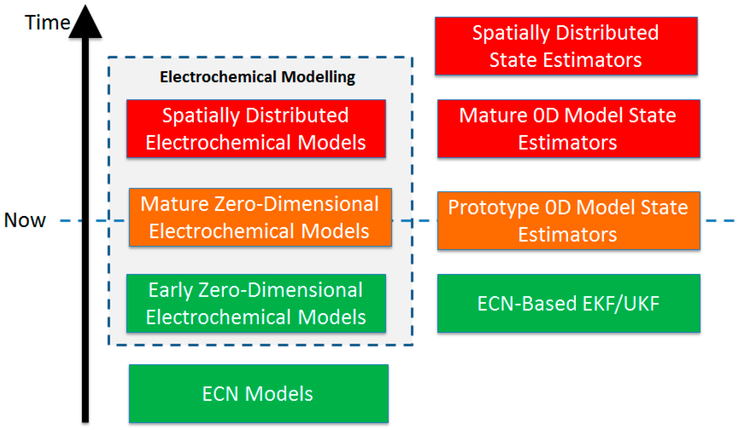
3. State-of-the-Art Li-S Cell Modelling and State Estimation Techniques

One of the most important aspects of technology readiness level (TRL) of a new battery technology is the availability of a proper battery management system (BMS) for that. BMS is responsible for different tasks such as protecting cells from damage, prolonging life of the battery, and maintaining the battery in a state in which it can meet the requirements of the application for which it was designed. This would finally lead to safe and optimal use of the battery pack. The first step to design a proper BMS is sufficient understanding of the cell’s behavior in order to develop operational predictive models of the cell. This is usually done by performing experimental tests on the cell along with electrochemical analysis of cell’s components. Electrochemical discussions on a Li-S cell’s components and the manufacturing process are out of the framework of this study however, more practical aspects of cell modelling and state estimation are of interest here.
BMS development contains different parts such as thermal analysis of the cell along with temperature monitoring and control, developing low-fidelity models and state estimation algorithms to be used in real-time on control boards, etc. Accurate estimation of the battery states, such as battery state-of-charge (SoC) and state-of-health (SoH), is vital for a safe battery charge/discharge and optimal usage of the battery. Particularly for a Li-S battery pack, no such BMS is available in the market yet, however, early stage algorithms and electronic boards are available. Figure 2 shows a prototype Li-S battery pack including 16 cells connected in series which is developed by OXIS Energy [12]. The BMS topology is distributed type with 16 small boards connected to each cell. As suggested by the cell’s manufacturer, temperature, current and voltage of each cell is directly measured and controlled in such structure.
As discussed in [42], there are various approaches in the literature for cell modelling including analytical, statistical, electrochemical and equivalent circuit network (ECN) modelling approaches. In this study, we are more interested in practical modelling approaches to be used on BMS boards. Reduced-order electrochemical and ECN models are two good choices for this purpose. There is no available reduced-order electrochemical model of a Li-S cell in the literature to be used on BMS boards however; there are lots of good works in which electrochemical models have been developed for a Li-S cell [43,44,45,46]. As an example, in [46], a zero-dimensional model has been developed with the ability to predict the behavior of a Li-S cell during charge and discharge at a good level of accuracy. Although such models are quite useful for understanding the complex behavior of a Li-S cell, more work is needed in this area to develop more practical models suitable for BMS boards.
When electrochemists create models, they usually do so ‘as scientists’: the aim of a scientific model is to enhance understanding. Of course, no model is perfect, and the pure scientist uses model imperfections to identify gaps in present knowledge and as the inspiration for further research. The aim is to improve understanding and get a ‘better model’. However, at some point, cells may be put to practical use, and at this point, the application engineer will often have to make do with the best models available at that time, despite the model’s imperfections. In such a situation, ECN modelling approach is very common among researchers and engineers. There are few studies on Li-S cell ECN modelling in the literature. The original application of ECN models to lithium sulfur was carried out by in works such as [10,11,47,48].
As mentioned before, accurate estimation of the battery states (SoC and SoH), is vital for a safe battery charge/discharge and optimal usage of the battery. The state estimation theory has been developed as part of the control theory and is available in textbooks [49]. It states that when direct measurements are not available, it is necessary to estimate the internal state of a system. In our case, the battery states are also not directly measurable. Essentially, the idea of control-oriented state estimation is that if the estimate contains an error term, then this will result in a prediction error: this will result in a ‘correction’ to the internal state. Depending on the system dynamics and how the correction is designed, it is often possible to guarantee that the state estimate will converge to the true estimate. It is worth mentioning that unknown dynamics and external disturbances can have a negative effect on the estimation results. However, the methods from control theory explicitly allow for modelling errors and uncertainty. The motivation for feedback control is to deal with this uncertainty and mitigate its effects [50]. It is beyond the scope of this paper to go into the detailed derivation of estimators: perhaps the best known are the Kalman filter family, initiated by Rudolph Kalman’s seminal work [51]. This has been successfully applied to lithium-ion batteries by many authors, notably Plett [52,53,54].
These techniques have recently been applied to Li-S cell for the first time. In [55], Extended Kalman Filter (EKF), Unscented Kalman Filter (UKF) and Particle Filter techniques are all investigated for use on real Li-S cell state estimation subject to automotive drive cycles. Closely related to these is a set of techniques from artificial intelligence based on Adaptive Neuro-Fuzzy Inference Systems (ANFIS). In [56], an ANFIS structure is designed to estimate a real Li-S cell’s SoC based on real-time cell model parameterization. In this approach, parameters of an ECN cell model were used as an indicator of SoC in real-time. While it should be very clear to the reader that an ECN model is likely to be in some ways a gross over-simplification, what these works demonstrate is that even a fairly ‘rough and ready’ model can be used.
One of the big challenges in state estimation and control of a Li-S cell is its flat open-circuit-voltage (OCV) curve vs. SoC. The Li-S cell SoC range can be divided into two parts, usually referred to as the ‘high plateau’ (HP) and ‘low plateau’ (LP) as shown in Figure 3. There is a breakpoint at around 75% SOC that determines the boundary between the two plateaus. This transition, which is caused by a sudden change in electrochemical reactions inside the Li-S cell, might shift slightly to the right or left under different discharge conditions [56]. The flat shape of the OCV curve at LP makes the system unobservable based on control theory as discussed in [56]. This unique feature of the Li-s cell makes its control a very challenging task.
Another challenge in estimation and control of the Li-S cell is its high sensitivity to the temperature variation. This subject is discussed in more detail in [11,48]. For example, Figure 4 shows the dependency of a Li-S cell’s ohmic resistance to the temperature variation where temperature and Li-S cell’s ohmic resistance are inversely proportional. Temperature also has an effect on ‘plateau change’ (the break-point between HP and LP regions) as depicted in Figure 4. The results in [11] demonstrate that the HP region shrinks as the temperature increases. The break-point moves from 65% at 10 °C to 85% at 50 °C. Figure 4 also demonstrates that Li-S cell’s ohmic resistance has a highly nonlinear relationship with SoC. Ohmic resistance is low at high SOC, increasing linearly at HP by charge depleting. There is a break-point at the end of HP where cell’s ohmic resistance starts decreasing after that. At LP, Li-S cell’s ohmic resistance almost has a parabolic shape with a minimum point in the middle [11].
State estimation developments are expected to take into account improvements in the state of the art executable models. A ‘zero dimensional’ electrochemical model for Li-S cell has recently been published [46] and while there is further work to be done to extend this and parameterize real, physical cells, this is a promising direction for future exploitation. As the state of the art in modelling develops, it is envisaged that it will be possible to explore state-of-the-art techniques for rapid online execution of spatially distributed models [57]. A possible road map is shown in Figure 5, including contributions by control engineers follow developments in fast-executing electrochemical models.

4. Current and Future Applications of Li-S Battery

Systems designers will use Li-S batteries where the characteristics of the technology are best suited to the application. If we first understand the inherent characteristics, we can then match them to the most suitable markets.
As described in Section 2, Li-S chemistry has a very high theoretical specific energy up to 600 Wh.kg−1 practically, but a lower density than Li-ion—typically a 1:1 gravimetri:volumetric ratio can be expected for Li-S pouch cells. Therefore, Li-S cells will be lighter than Li-ion, but not necessarily smaller. Cycle life and power capability are currently low compared to Li-ion, but are expected to rise in the future as the chemistry is further developed. For cells to pass qualification testing such as UN38.3 transportation certification to allow them to be offered for sale and shipped worldwide, they will need to be capable of surviving temperatures between −42 °C and +74 °C [59]. Therefore, it is assumed that they are capable of operating between −20 °C and +60 °C if used in applications, even if the optimal operating temperature range is much smaller.

4.1. Current Applications

Current Li-S cells are light, with a number of companies reporting to have developed cells that are 400 Wh.kg−1 [60,61] however, power and cycle life is considered to be low compared to Li-ion systems with typical cycle life rarely exceeding 100 cycles compared with many thousands for Li-ion and constant current power density usually limited above 2 C. This limits Li-S today to applications that need very low mass batteries, with low power and cycle life needs.
The most well known applications with requirements like this are high altitude long endurance unmanned aerial vehicles (HALE UAVs). They fly in the stratosphere, using solar panels to power their propulsion systems, payloads and recharge their batteries during the day. They then use the batteries to power the systems at night, allowing the UAVs to stay airborne for days, weeks, or months on end. The best known of these systems are Project Loon [62], Facebook Aquila [63] and the Airbus Zephyr [64]. Because they charge their batteries during the day and discharge them at night, the power rates are very low (approximately C/10) as one complete cycle takes 24 h. In addition to that, the cycle life requirement is thought to be low for these aircraft as the maximum time that any of them has spent in the air is Project Loon at 190 days [65], while the Airbus Zephyr has managed a more modest 14 days [66]. Lastly, each of these UAVs has emphasized the low weight of their systems, as it allows them to stay aloft for longer.
Therefore, Li-S cells that are lighter than any other cells on the market, that can cope with a C/10 charge and discharge rate and have a cycle life of above 14 cycles, but preferably around 200 cycles will first be deployed in HALE UAVs. This is expected to be a high value, low-to-moderate volume market. Scope for other applications outside of HALE UAVs is limited without further development of the technology, as few applications have such low power and cycle life requirements.

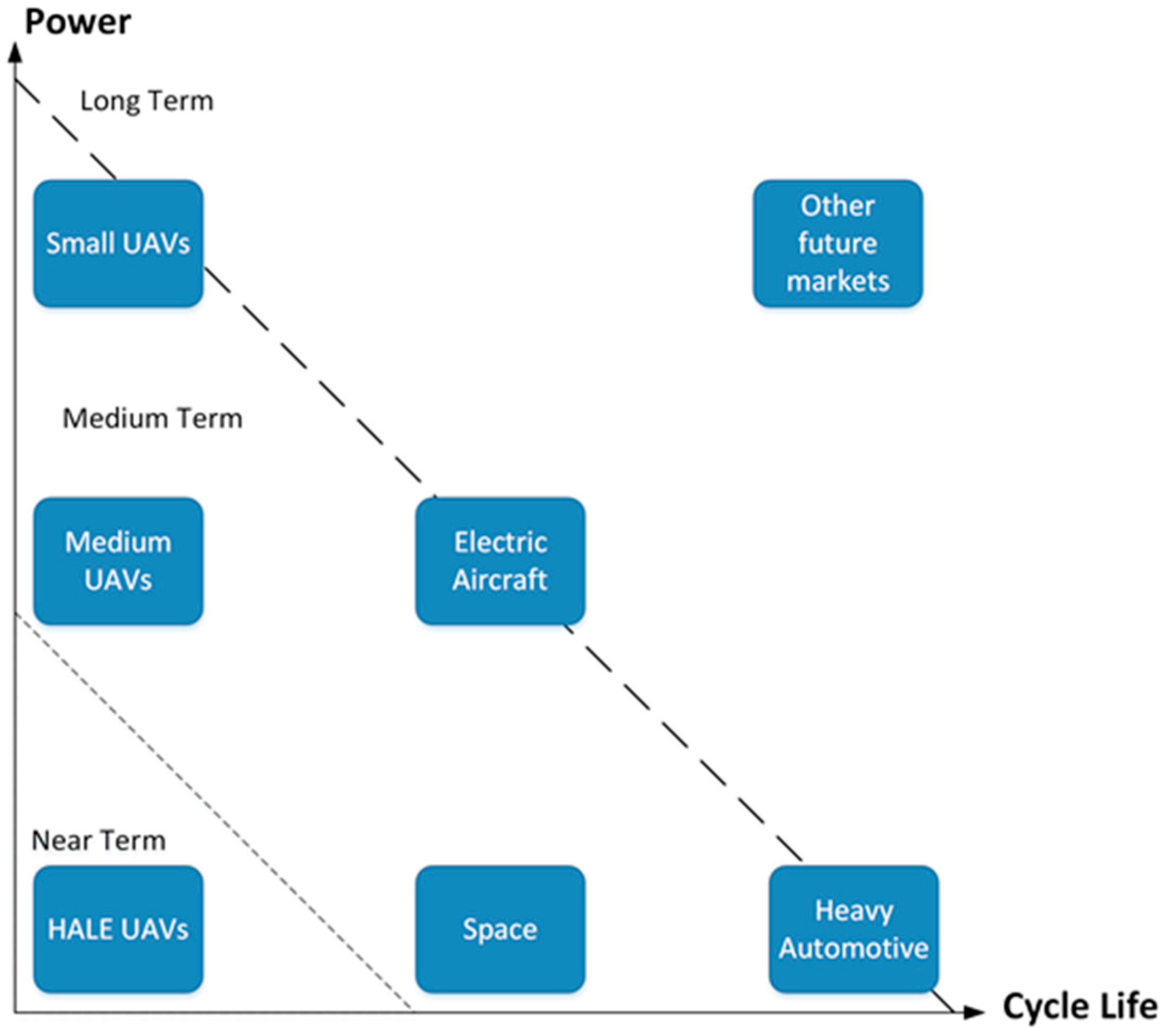
4.2. Future Applications

Future applications will depend on what improvements are made to Li-S, they break down into three areas: cycle life, power, both cycle life and power. As most academic research is focused on developing a single cell component (electrolyte, cathode, anode protection) rather than a holistic cell, it is likely that progress in this area will result initially in cells with either improved cycle life or improved power density. It can be expected that a period of integration will follow, eventually culminating in a high performance Li-S cell that can achieve many thousands of cycles and high C rates, whilst maintaining gravimetric energy density of >400 Wh.kg−1. Even before this final cell is developed, there are many applications with requirements of just two of energy, cycle life and power which would serve as entry markets for Li-S cells.

4.2.1. Li-S with Improved Cycle Life

A 400 Wh.kg−1 cell with improved cycle life, but low power capability is going to be useful in a number of areas.
First, it will lower the cost operation for HALE UAVs as they will be able to remain airborne for longer and therefore need less battery changes during the service life of the UAV.
Second, the space sector is expected to be a suitable avenue for Li-S cells with high cycle life. Because satellites cannot be landed and refitted with fresh batteries, the cells must work for the entire life of the satellite, leading to a high cycle life requirement of tens of thousands of cycles. However, lowering the mass of the batteries in a satellite would result in significant cost savings as a typical launch has a cost of approximately $20,000 per kg of payload [67]. If the mass of current Li-ion batteries can be halved by replacement with Li-S, this would represent a substantial saving. Like HALE UAVs, this is expected to be a high value, low-to-moderate volume market.
Thirdly, it is predicted that the heavy automotive vehicle market will be suitable, particularly for applications such as buses and trucks. Li-S cells would be useful here as the large batteries needed (which could be in the region of 400 kWh) would be very heavy if Li-ion was used and Li-S could offer a mass saving. Reducing the mass of the batteries would allow the mass of payload to increase, which in turn could lower costs and/or increase revenue. Both buses and trucks tend to be used all day, and then spend overnight in a depot unused. This would allow a regime where they are discharged over the course of the day and recharged at night, needing only low power rates of around C/10 (although hill climbs could require more for short periods). Most heavy automatic vehicles are used daily, so a service life of five years would require a cell cycle life of 1800 before 80% BoL capacity was hit. It would be higher if the service life is expected to be longer. It is expected to be a low value, high volume market.

4.2.2. Li-S with Improved Power

A 400 Wh.kg−1 Li-S cell with good power capability (e.g., 5C+) but low cycle life will be useful to the following applications:
Smaller UAVs, such as hobby/short duration drones used for pleasure, mapping, deliveries or photography would be able to fly longer and/or carry larger payloads. These UAVs are already battery powered and therefore the market move to lighter cells would be fast. It is expected to be a low value, moderate volume market.
In addition to the small UAVs, larger drones, currently mainly used by security services for surveillance and other tasks with a flight time of 8–10 h could also switch from internal combustion engines to batteries to save cost. This market is also expanding to civilian sectors, so it may be medium value, low volume to begin with, but the volume could rise to a moderate level.
Early stage electric aircraft may also begin to be developed, as the power capability will allow high drain maneuvers such as take-off and the high specific energy would make it efficient. Entrepreneur Elon Musk has stated that at 400 Wh.kg−1, cell would make electric aircraft viable [68]. It is thought that this market would be slow to develop as it would be a new application and would also need to pass regulatory approvals like any conventional aircraft. It is expected to be a high cost, low volume market in this concept stage, but would require further chemistry development to make it mainstream.

4.2.3. Li-S with Improved Cycle Life and Power

This would be the late stage of Li-S development, as a cell with high specific energy, high power and high cycle life is very difficult to achieve. It is considered the furthest off of the developments.
It would be expected that the above described markets would expand further and that Li-S would become the battery of choice for most aerospace and space applications. Further markets such as the heavy automotive vehicle market would also be expected to expand and there will undoubtedly be other markets that adopt the technology that are not obvious at this time. It is thought that other, denser technologies will dominate the consumer electronics and consumer electric vehicle markets, unless advances can be made in Li-S research to make major gains in volumetric energy.
Figure 6 summarizes the Li-S cell applications versus improvements to power, cycle life and timescale.

5. Conclusions

Lithium-sulfur battery technology readiness and its applications were discussed and relevant studies were reviewed. Li-S was presented as a promising technology with advantages over alternative battery technologies in the market. The main advantage of Li-S is the extremely high gravimetric energy capability, providing a potential energy density around 600 Wh.kg−1, that makes it suitable for applications where weight is a critical parameter. In addition to the energy capabilities of Li-S, another key advantage is the cheap, abundant and non-toxic raw materials that go into the cell. In addition, at a user-level, Li-S cells do not require top-up charging when in storage which presents a significant advantage over Li-ion cells which require regular maintenance.
Despite the advantages of the Li-S battery technology, there are several issues with this technology as well. Although some of the issues may be overcome by improved engineering solutions, the majority of them are related to the very complex working mechanism of Li-S, significantly different from classical Li-ion. As an example, the complex reaction mechanism causes difficulty in the modelling of Li-S cells at both a mechanistic and systems level. This leads to the development of extremely complex models which are both resource and time heavy and not appropriate for real-life applications, or over-simplified models which do not accurately describe real cell behavior. The existing studies focused on Li-S cell modelling and state estimation were reviewed and challenges in control of a Li-S cell such as its flat open-circuit-voltage curve and high sensitivity to temperature variation were explained however, the research in this area is ongoing.
In the last part of this study, current and future applications of the Li-S battery technology were discussed. Current applications of Li-S battery technology is limited to low power and cycle life requirements such as high altitude long endurance unmanned aerial vehicles (HALE UAVs). Future applications of Li-S battery were then discussed in three areas, the need for more cycle life, the need for more power, and the need for both.

Acknowledgments

This research was undertaken as part of the ‘Revolutionary Electric Vehicle Battery’ (REVB) project, co-funded by Innovate UK /EPSRC (TS/L000903/1 and EP/L505286/1). Data underlying this study can be accessed through the Cranfield University repository.

Author Contributions

A.F. and D.J.A. have mainly contributed in the “State-of-the-Art Li-S Cell Modelling and State Estimation Techniques” section. L.O. and S.W. have mainly contributed in the “Li-S Battery Technology: Advantages and Limitations” section. T.C. has mainly contributed in the “Current and Future Applications of Li-S Battery” section. A.F. has also prepared the whole structure of the paper, formatting, connection between different sections, the “introduction” and “conclusion” sections.

Conflicts of Interest

The authors declare no conflict of interest.

References

  1. Zhang, X.; Xie, H.; Kim, C.-S.; Zaghib, K.; Mauger, A.; Juliend, C.M. Advances in Lithium-Sulfur Batteries. Mater. Sci. Eng. R Rep. 2017, 121, 1–29. [Google Scholar] [CrossRef]
  2. Chen, L.; Shaw, L.L. Recent advances in lithium–sulfur batteries. J. Power Sources 2014, 267, 770–783. [Google Scholar] [CrossRef]
  3. Manthiram, A.; Fu, Y.; Chung, S.; Zu, C.; Su, Y. Rechargeable Lithium–Sulfur Batteries. Chem. Rev. 2014, 114, 11751–11787. [Google Scholar] [CrossRef] [PubMed]
  4. Song, M.K.; Cairns, E.J.; Zhang, Y. Lithium/sulfur batteries with high specific energy: Old challenges and new opportunities. J. Nanoscale 2013. [Google Scholar] [CrossRef] [PubMed]
  5. Zhang, G.; Zhang, Z.W.; Peng, H.J. A Toolbox for Lithium–Sulfur Battery Research: Methods and Protocols. J. Small Methods 2017, 1. [Google Scholar] [CrossRef]
  6. Kawase, A.; Shirai, S.; Yamoto, Y. Electrochemical reactions of lithium–sulfur batteries: An analytical study using the organic conversion technique. Phys. Chem. Chem. Phys. 2014, 16, 9344. [Google Scholar] [CrossRef] [PubMed]
  7. Diaoz, Y.; Xie, K.; Xiong, S.; Hong, X. Analysis of Polysulfide Dissolved in Electrolyte in Discharge-Charge Process of Li-S Battery. J. Electrochem. Soc. 2012, 159, A421–A425. [Google Scholar]
  8. Mikhaylik, Y.V.; Akridge, J.R. Polysulfide Shuttle Study in the Li/S Battery System. J. Electrochem. Soc. 2004, 151, A1969–A1976. [Google Scholar] [CrossRef]
  9. Minton, G.; Purkayastha, R.; Lue, L. A Non-Electroneutral Model for Complex Reaction-Diffusion Systems Incorporating Species Interactions. J. Electrochem. Soc. 2017, 164, E3276–E3290. [Google Scholar] [CrossRef]
  10. Fotouhi, A.; Auger, D.J.; Propp, K.; Longo, S. Electric Vehicle Battery Parameter Identification and SOC Observability Analysis: NiMH and Li-S Case Studies. IET Power Electron. 2017. [Google Scholar] [CrossRef]
  11. Fotouhi, A.; Auger, D.J.; Propp, K.; Longo, S.; Purkayastha, R.; O’Neill, L.; Walus, S. Lithium-Sulfur Cell Equivalent Circuit Network Model Parameterization and Sensitivity Analysis. IEEE Trans. Veh. Technol. 2017, 66, 7711–7721. [Google Scholar] [CrossRef]
  12. OXIS Energy. Available online: http://www.oxisenergy.com (accessed on 29 September 2017).
  13. Sion Power. Available online: http://www.sionpower.com (accessed on 29 September 2017).
  14. LG Chem and Sion Power Partnership. Available online: http://pushevs.com/2016/10/07/lg-chem-sion-power-partnership/ (accessed on 29 September 2017).
  15. Sony Developing High-Capacity Rechargeable Battery. Available online: http://techon.nikkeibp.co.jp/atclen/news_en/15mk/121800252/?n_cid=nbptec_tecrs (accessed on 29 September 2017).
  16. Agostini, M.; Hassoun, J.; Yamada, T.; Aihara, Y.; Scrosati, B. All Solid-State Lithium–Sulfur Battery Using a Glass-Type P2S5–Li2S Electrolyte: Benefits on Anode Kinetics. J. Electrochem. Soc. 2015, 162, A646–A651. [Google Scholar]
  17. Jia, X.; Nazar, L.F. Advances in Li–S batteries. J. Mater. Chem. 2010. [Google Scholar] [CrossRef]
  18. Hagen, M.; Fanz, P.; Tübke, J. Cell energy density and electrolyte/sulfur ratio in Li–S cells. J. Power Sources 2014, 264, 30–34. [Google Scholar] [CrossRef]
  19. Hagen, M.; Hanselmann, D.; Ahlbrecht, K.; Maça, R.; Gerber, D.; Tübke, J. Lithium-sulfur cells: The Gap between the state-of-the-art and the requirements for high energy battery cells. Adv. Energy Mater. 2015, 5, 1401986. [Google Scholar] [CrossRef]
  20. Hunt, I.; Patel, Y.; Szczygielski, M.; Kabacik, L.; Offer, G. Lithium sulfur battery nail penetration test under load. J. Energy Storage 2015, 2, 25–29. [Google Scholar] [CrossRef]
  21. Hofmann, A.F.; Fronczek, D.N.; Bessler, W.G. Mechanistic modeling of polysulfide shuttle and capacity loss in lithium-sulfur batteries. J. Power Sources 2014, 259, 300–310. [Google Scholar] [CrossRef] [Green Version]
  22. Wild, M.; O’Neill, L.; Zhang, T.; Purkayastha, R.; Minton, G.; Marinescu, M.; Offer, G. Lithium sulfur batteries, a mechanistic review. Energy Environ. Sci. 2015, 8, 3477–3494. [Google Scholar] [CrossRef]
  23. Walus, S.; Barchasz, C.; Colin, J.F.; Martin, J.F.; Elkaïm, E.; Leprêtre, J.C.; Alloin, F. New insight into the working mechanism of lithium–sulfur batteries: In situ and operando X-ray diffraction characterization. Chem. Commun. 2013, 49, 7899–7901. [Google Scholar] [CrossRef] [PubMed]
  24. Waluś, S.; Barchasz, C.; Bouchet, R. Lithium/Sulfur Batteries upon Cycling: Structural Modifications and Species Quantification by In Situ and Operando X-ray Diffraction Spectroscopy. Adv. Energy Mater. 2015, 5. [Google Scholar] [CrossRef]
  25. Barghamadi, M.; Best, A.S.; Bhatt, A.I.; Hollenkamp, A.F.; Musameh, M.; Ress, R.J. Lithium-sulfur batteries—The solution is in the electrolyte, but is the electrolyte a solution? Energy Environ. Sci. 2014, 7, 3902–3920. [Google Scholar] [CrossRef]
  26. Diao, Y.; Xie, K.; Xiong, S.; Hong, X. Shuttle phenomenon the irreversible oxidation mechanism of sulfur active material in Li-S battery. J. Power Sources 2013, 235, 181–186. [Google Scholar] [CrossRef]
  27. Zoski, C.G. Handbook of Electrochemistry; Elsevier: Amsterdam, The Netherlands, 2007. [Google Scholar]
  28. Luo, J.; Lee, R.; Jin, J.; Weng, Y.; Fang, C.; Wu, N.L. A dual-functional polymer coating on a lithium anode for suppressing dendrite growth and polysulfide shuttling in Li–S batteries. Chem. Commun. 2017, 53, 963. [Google Scholar] [CrossRef] [PubMed]
  29. Tian, H.; Seh, Z.W.; Yan, K.; Fu, Z.; Tang, P.; Lu, Y.; Zhang, R.; Legut, D.; Cui, Y.; Zhang, Q. Theoretical Investigation of 2D Layered Materials as Protective Films for Lithium and Sodium Metal Anodes. Adv. Energy Mater. 2017, 7, 1602528. [Google Scholar] [CrossRef]
  30. McCloskey, B. Attainable Gravimetric and Volumetric Energy Density of Li–S and Li Ion Battery Cells with Solid Separator-Protected Li Metal Anodes. J. Phys. Chem. Lett. 2015, 6, 4581–4588. [Google Scholar] [CrossRef] [PubMed]
  31. Yan, J.; Liu, X.; Li, B. Capacity Fade Analysis of Sulfur Cathodes in Lithium-Sulfur Batteries. Adv. Sci. 2016, 3, 1600101. [Google Scholar] [CrossRef] [PubMed]
  32. Bruce, P.G.; Freunberger, S.A.; Hardwick, L.J.; Tarascon, J. Li–O2 and Li–S batteries with high energy storage. Nat. Mater. 2012, 11, 19–29. [Google Scholar] [CrossRef] [PubMed]
  33. Li, C.; Zhang, H.; Otaegui, L. Estimation of energy density of Li-S batteries with liquid and solid Electrolytes. J. Power Sources 2016, 326, 1–5. [Google Scholar] [CrossRef]
  34. Scrosati, B.; Abraham, K.M.; van Schalkwijk, W.A.; Hassoun, J. Lithium Batteries: Advanced Technologies and Applications; Wiley: New York, NY, USA, 2013; Chapter 8. [Google Scholar]
  35. Pressure Tolerant Lithium Sulfur Battery. Available online: http://noc.ac.uk/projects/pressure-tolerant-lithium-sulfur-battery (accessed on 29 September 2017).
  36. Jeschull, F.; Brandell, D.; Edströma, K.; Lacey, M. A stable graphite negative electrode for the lithium–sulfur battery. Chem. Commun. 2015, 51, 17100–17103. [Google Scholar] [CrossRef] [PubMed]
  37. Krause, A.; Dörfler, S.; Piwko, M.; Wisser, F.M.; Jaumann, T.; Ahrens, E.; Giebeler, L.; Althues, H.; Schädlich, S.; Grothe, J.; et al. High Area Capacity Lithium-Sulfur Full-cell Battery with Prelitiathed Silicon Nanowire-Carbon Anodes for Long Cycling Stability. Sci. Rep. 2016, 6, 27982. [Google Scholar] [CrossRef] [PubMed]
  38. Piwko, M.; Kuntze, T.; Winkler, S.; Straach, S.; Härtel, P.; Althues, H.; Kaskela, S. Hierarchical columnar silicon anode structures for high energy density lithium sulfur batteries. J. Power Sources 2017, 351, 183–191. [Google Scholar] [CrossRef]
  39. Cao, R.; Xu, W.; Lv, D.; Xiao, J.; Zhang, J.G. Anodes for Rechargeable Lithium-Sulfur Batteries. Adv. Energy Mater. 2015, 5. [Google Scholar] [CrossRef]
  40. Yuan, Z.; Peng, H.; Hou, T.; Huang, J.; Chen, C.; Wang, D.; Cheng, X.; Wei, F.; Zhang, Q. Powering Lithium–Sulfur Battery Performance by Propelling Polysulfide Redox at Sulfiphilic Hosts. Nano Lett. 2016, 16, 519–527. [Google Scholar] [CrossRef] [PubMed]
  41. Li, W.; Zheng, G.; Yang, Y.; Seh, Z.W.; Liu, N.; Cui, Y. High-performance hollow sulfur nanostructured battery cathode through a scalable, room temperature, one-step, bottom-up approach. Proc. Natl. Acad. Sci. USA 2013, 110, 7148–7153. [Google Scholar] [CrossRef] [PubMed]
  42. Fotouhi, A.; Auger, D.J.; Propp, K.; Longo, S.; Wild, M. A review on electric vehicle battery modelling: From lithium-ion toward lithium-sulphur. Renew. Sustain. Energy Rev. 2016, 56, 1008–1021. [Google Scholar] [CrossRef]
  43. Ghaznavi, M.; Chen, P. Sensitivity analysis of a mathematical model of lithium-sulfur cells part I. J. Power Sources 2014, 257, 394–401. [Google Scholar] [CrossRef]
  44. Ghaznavi, M.; Chen, P. Sensitivity analysis of a mathematical model of lithium-sulfur cells part II. J. Power Sources 2014, 257, 402–411. [Google Scholar] [CrossRef]
  45. Neidhardt, J.P.; Fronczek, D.N.; Jahnke, T.; Danner, T.; Horstmann, B.; Bessler, W.G. A Flexible Framework for Modeling Multiple Solid, Liquid and Gaseous Phases in Batteries and Fuel Cells. J. Electrochem. Soc. 2012, 159, A1528–A1542. [Google Scholar] [CrossRef]
  46. Marinescu, M.; Zhang, T.; Offer, G.J. A zero dimensional model of lithium–sulfur batteries during charge and discharge. Phys. Chem. Chem. Phys. 2016, 18, 584–593. [Google Scholar] [CrossRef] [PubMed]
  47. Knap, V.; Stroe, D.; Swierczynski, M.; Teodorescu, R.; Schaltz, E. Investigation of the Self-Discharge Behavior of Lithium-Sulfur Batteries. J. Electrochem. Soc. 2016, 163, A911–A916. [Google Scholar] [CrossRef]
  48. Propp, K.; Marinescu, M.; Auger, D.; O’Neill, L.; Fotouhi, A.; Somasundaram, K.; Offer, G.; Minton, G.; Longo, S.; Wild, M.; et al. Multi-temperature state-dependent equivalent circuit discharge model for lithium-sulfur batteries. J. Power Sources 2016, 328, 289–299. [Google Scholar] [CrossRef]
  49. Aström, K.J.; Murray, R.M. Feedback Systems: An Introduction for Scientists and Engineers; Princeton University Press: Princeton, NJ, USA, 2008. [Google Scholar]
  50. Vinnicombe, G. Uncertainty and Feedback: ℌ Loop-Shaping and the υ-Gap Metric; Imperial College Press: London, UK, 2000. [Google Scholar]
  51. Kalman, R.E. A New Approach to Linear Filtering and Prediction Problems. Trans. AMSE J. Basic Eng. 1960, 82, 35–45. [Google Scholar] [CrossRef]
  52. Plett, G.L. Extended Kalman filtering for battery management systems of LiPB-based HEV battery packs—Part 1. Background. J. Power Sources 2004, 134, 252–261. [Google Scholar] [CrossRef]
  53. Plett, G.L. ‘Extended Kalman filtering for battery management systems of LiPB-based HEV battery packs—Part 2. Modelling and Identification’. J. Power Sources 2004, 134, 262–276. [Google Scholar] [CrossRef]
  54. Plett, G.L. Extended Kalman filtering for battery management systems of LiPB-based HEV battery packs—Part 3. State and Parameter Estimation. J. Power Sources 2004, 134, 277–292. [Google Scholar] [CrossRef]
  55. Propp, K.; Auger, D.J.; Fotouhi, A.; Longo, S.; Knap, V. Kalman-variant estimators for state of charge in lithium-sulfur batteries. J. Power Sources 2017, 343, 254–267. [Google Scholar] [CrossRef]
  56. Fotouhi, A.; Auger, D.J.; Propp, K.; Longo, S. Lithium-Sulfur Battery State-of-Charge Observability Analysis and Estimation. IEEE Trans. Power Electron. 2017. [Google Scholar] [CrossRef]
  57. Bizeray, A.M.; Zhao, S.; Duncan, S.R.; Howey, D.A. Lithium-ion battery thermal-electrochemical model-based state estimation using orthogonal collocation and a modified extended Kalman filter. J. Power Sources 2015, 296, 400–412. [Google Scholar] [CrossRef]
  58. Auger, D.J. Using Ideas from Control Theory in the Modelling and Management of Lithium-Sulfur Batteries; University of Oxford: Oxford, UK, 6 February 2017. [Google Scholar]
  59. Recommendations on the TRANSPORT OF DANGEROUS GOODS. Available online: http://www.batteryspace.com/prod-specs/UN_Test_Manual_Lithium_Battery_Requirements%205.1.pdf (accessed on 20 November 2017).
  60. OXIS Energy Advances its Lithium Sulfur (Li-S) Cell Technology to 400 Wh/kg. Available online: https://oxisenergy.com/oxis-energy-advances-lithium-sulfur-li-s-cell-technology-400whkg/ (accessed on 20 November 2017).
  61. Sion Power Delivers Next Generation Battery Performance through Patented Licerion® Technology. Available online: http://www.sionpower.com/media-center.php?code=sion-power-delivers-next-generation-battery-perfor (accessed on 20 November 2017).
  62. What is Project Loon. Available online: https://x.company/loon/ (accessed on 20 November 2017).
  63. The Technology behind Aquila. Available online: https://www.facebook.com/notes/mark-zuckerberg/the-technology-behind-aquila/10153916136506634/ (accessed on 20 November 2017).
  64. Zephyr, the High Altitude Pseudo-Satellite. Available online: http://defence.airbus.com/portfolio/uav/zephyr/ (accessed on 20 November 2017).
  65. And the 2016 Golden Balloon Goes to…. Available online: https://plus.google.com/+ProjectLoon/posts/2vGeQAXF4Qo (accessed on 20 November 2017).
  66. ‘Eternal’ Solar Plane’s Records Are Confirmed. Available online: http://www.bbc.co.uk/news/science-environment-12074162 (accessed on 20 November 2017).
  67. Advanced Space Transportation Program: Paving the Highway to Space. Available online: https://www.nasa.gov/centers/marshall/news/background/facts/astp.html (accessed on 20 November 2017).
  68. Elon Musk: Tesla Has ‘No Plans’ For an Electric Plane—Yet. Available online: https://www.inverse.com/article/32623-tesla-ceo-elon-musk-plane-yet (accessed on 20 November 2017).
Figure 1. Schematic showing the operation of a Li-S cell during discharge.
Energies 10 01937 g001
Figure 2. A 16-cell Li-S pack developed by OXIS Energy.
Energies 10 01937 g002
Figure 3. Li-S cell terminal voltage during slow discharge at C/30.
Energies 10 01937 g003
Figure 4. Li-S cell’s ohmic resistance vs. SoC at different temperatures [11].
Energies 10 01937 g004
Figure 5. Expected road map for state estimation in Li-S: colors are a ‘traffic light’ indication of technology readiness, with green representing most ready, and red representing furthest off [58].
Energies 10 01937 g005
Figure 6. Li-S cell applications versus improvements to power, cycle life and timescale.
Energies 10 01937 g006
Table 1. Specifications of a prototype Li-S cell manufactured by OXIS Energy [12].
TypeRechargeable Lithium-Sulfur Pouch Cell
Remarks: Li Metal Anode
cell dimension176 mm × 114 mm × 13.7 mm
maximum voltage2.45 V
nominal voltage2.05 V
capacity21 Ah (at 0.2 C, 30 °C)
weight233 ± 5 g
volume0.252 L
recommended charging condition in applications2.1 A constant current (C/10) at 30 °C
(charge stop at 2.45 V or 11 h max charge time)
recommended discharging condition in applicationspeak discharge current: 2 C
maximum continuous discharge current (at 30 °C): 1.5 C
maximum continuous power60 W (at 30 °C)
optimum operating temperature30 °C
Cycle number before getting 80% of the beginning-of-life capacity180 cycles
(cycled at 30 °C in a standard life test regime)

