Article

Envelope Design Optimization by Thermal Modelling of a Building in a Warm Climate

by
Cristina Baglivo
1,
Paolo Maria Congedo
1,
Matteo Di Cataldo
2,
Luigi Damiano Coluccia
1 and
Delia D’Agostino
3,*
1
Department of Engineering for Innovation, University of Salento, 73100 Lecce, Italy
2
Design Innovation Building (DIB) Studio Limited, Kemp House 152 City Road, London EC1V 2NX, UK
3
European Commission, Joint Research Centre (JRC), Directorate C—Energy, Transport and Climate, Energy Efficiency and Renewables, Via E. Fermi 2749, Ispra, I-21027 Varese, Italy
*
Author to whom correspondence should be addressed.
Energies 2017, 10(11), 1808; https://doi.org/10.3390/en10111808
Submission received: 31 August 2017 / Revised: 27 October 2017 / Accepted: 3 November 2017 / Published: 9 November 2017

Abstract

:
Finding the most appropriate configuration of building components at the design stage can reduce energy consumption in new buildings. This study aims to optimize the design of the envelope of a new residential building located in a warm climate (southern Italy). The thermal behaviour of the building has been analysed to evaluate the indoor operative air temperature for several configurations. The building prototype has been modelled using the dynamic simulation software TRNSYS 17 (A transient system simulation program, University of Wisconsin, Solar Energy Laboratory, USA, 2010) using a sequential search technique. Starting from the simplest building configuration, the main evaluated components are: walls, slab-on-ground floor, roof, shading, windows and internal heat loads. For each of these components, different design options have been modelled and compared in terms of indoor thermal comfort. Comfort parameters have also been taken into account to evaluate users’ satisfaction with the optimized configurations. The study of the operative air temperature demonstrates that the absence of insulating layers in the ground floor ensures a lower internal temperature in summer. The paper shows how each component impacts the thermal behaviour of the whole building. It highlights the usefulness of the envelope design optimization that is characterized by high values of heat storage capacity, enabling internal temperature fluctuations to be kept under control, especially during summer.

HIGHLIGHTS:

  • The envelope design of a residential building has been optimized for a warm climate.
  • Several envelope design options have been evaluated and compared.
  • Walls with a high internal areal heat capacity are preferable in a warm climate.
  • The absence of insulating layers on slab-on-ground floor provides lower temperature in summer.
  • Low emissivity glass and low solar absorbance roof reduce heat loads.

1. Introduction

Climate change is considered as one of the main concerns to be overcome at global level [1]. Improving the energy performance of buildings is a cost-effective way of fighting against climate change, alleviating energy resources depletion and environmental deterioration [2]. The construction sector is one of the largest energy consumers in all countries. It has been estimated to be responsible for consumption around 40% of natural resources, 70% of electricity and 12% of potable water [3]. At the same time, the built environment is the sector that offers the largest potential energy savings and greenhouse gas emissions reduction [4]. Furthermore, more efficient buildings can decrease energy needs for gas imports, and related imports costs, improving energy security. Reducing household energy bills can also alleviating fuel poverty and improving social and territorial cohesion at the European level.
Within this framework, European policies are focused on decreasing energy consumption in buildings [5]. New policies have introduced technical and regulatory measures to promote a more rational use of energy over the last decade. The Energy Efficiency Directive (EED) deals with a more efficient energy use throughout the energy chain, from its production to its final consumption [6]. Energy Performance of Buildings Directive (EPBD) introduces the new target of nearly zero energy buildings (NZEBs) from 2018 onwards [7]. Several benefits are linked to energy efficiency improvement, among them: energy security, job creation, fuel poverty alleviation, health and indoor comfort [2]. Building energy consumptions can be effectively reduced evaluating different building configurations at the design stage and selecting the most appropriate ones according to the specific characteristics of the building and the site.
This study aims to find out the best practice design of the envelope of a building located in a warm climate. Several studies have faced this issue in other climates [8,9,10]. Buildings placed in a cold climate adopt a technology of light multi-layered walls by using structural materials with low density, thermal isolation, wide thickness, low specific weight, low mass accumulation, to achieve very low steady thermal transmittance [11]. These techniques work toward bringing down winter heating costs. In a warm climate, the thermal overload is irreversible when radiation is not controlled and the free supply of heat indoors is mismanaged. This study focuses on the possibility to exploit large surfaces with thermal accumulation mass, that can store heat when necessary, and discharge it once the effect of solar radiation is exhausted. The methodology is based on the operative air temperature (TOP) monitoring.

1.1. Building Optimization

Simulation-based optimization tools are increasingly revealing their potential to decrease energy consumption at the design stage [12]. The first efforts of performing building energy simulations with an algorithmic optimization engine date back to the 80s [13,14], but these kinds of studies increased in the late 2000s [15]. In the last decade, a wide range of applications covering different aspects of building design have been performed, also thanks to a more powerful computer capacity [16,17].
Different building design variables can be considered with the purpose of reducing energy consumption [18,19]. Applications can also focus on maximizing the efficiency of Heating, Ventilation and Air Conditioning (HVAC) systems, ventilation, and photovoltaic collectors [20,21]. Several studies focus on the optimization of a single building component, such as windows or envelope [22,23]. Optimization problems can also relate to building renovation or internal comfort and relative humidity [24,25]. Studies that optimize the design of buildings are aimed at reducing the consumption of natural resources and life cycle costs, ensuring a reduced environmental impact [26]. Applying heuristic optimization techniques permit to combine many variables to obtain better quality solutions [27,28].
It is well-know that the most performing building configuration depends on several factors. Climate is certainly one of the key elements to decide for specific technological choices. For example, in colder climates, insulation and building tightness appear much more important. Buildings located in warm areas are subject to an elevated risk of internal overheating: for this reason, monitoring solar radiation and managing free gains are both important to guarantee a high level of comfort.
Building optimization can be based on several algorithms and assumptions. Recent research developments include the integration of optimization tools within the NZEBs design [29]. One promising approach is the use of automated mathematical building performance simulations (BPS) to evaluate different design options and obtain the optimum or near-optimum configuration while achieving fixed energy consumption levels (e.g., net zero energy). However, despite the well-recognised optimization potential, the integration of this process into industry is not yet reached and this toll remains at a research level. This is due to several factors, such as lack of resources, time, expertise, problem definition and constrains. Other limitations include model uncertainty, computation time, option assessment and results interpretation [30].

1.2. Envelope Measures for Energy Savings

A wide range of technologies, related to both envelope and systems, are becoming an integral part of building design able to reduce energy consumption thanks to innovative and efficient solutions. The envelope represents a key element to control the exchanges between indoors and outdoors [31]. Heat losses through the external surfaces amount to approximately 70% of the overall heat losses in buildings. Thermal insulation can guarantee less thermal losses while renewable energy production can balance energy consumption. ICT (Information and Communication Technology) provide a smarter use of energy, and technical systems are becoming more and more efficient [32]. These solutions enable more dynamic and interactive buildings, where technologies are used in conjunction with optimum design techniques that minimize summer heat gains and winter heat losses. Other measures include the use of passive heating and cooling techniques, a better use of daylight to reduce lighting. Therefore, an appropriate building design that selects technological measures according to the building needs becomes crucial.
Many energy-efficient buildings are designed with insulated walls and high efficiency windows, but a high thermal insulation can lead to a deterioration of the indoor air quality if there is no adequate ventilation system [33].
Different studies have shown how obtain high efficient external walls using natural and local materials with a reduced impact on the environment [34,35,36].
Amitava et al. [37] demonstrates that high values of thermal mass in multi-layer walls and roofs bring to good results in terms of internal thermal comfort, both in summer and winter, for buildings located in composite climates. In a warm climate, walls should be able to decrease the effects of external thermal stress during summertime. This is favoured by [38]:
  • low values of the decrement factor;
  • high values of the internal thermal areal capacity;
  • high values of the time shift.
Another central component of the envelope performance are windows. Double or triple glazed windows with low emissivity reduce energy consumption per m2 of glazed surface by more than 40% depending on the material and components. The design of windows in terms of sizing, position, type and shading system can significantly contribute to energy savings. Furthermore, films and coatings can be used on existing glazing to limit solar gains. Minne et al. [39] illustrate how different climates can affect windows behaviour, highlighting how low-solar gain windows bring a reduction of electricity needs. From an economic point of view, low-solar gain windows are more suitable in warm climates whereas high-solar gain windows are preferred for cold climates. J. Xamán et al. [40] underline the importance of using solar control films on double pane windows for buildings located in warm climates, in order to decrease overheating during the hottest months. Cappelletti et al. [41] relates windows performances with building location, climate and façade orientation.

1.3. Comfort Assessment and Thermal Behaviour

At the design stage, it is also important to consider thermal comfort whose definition relates to the thermal environment satisfaction expresses by users. This can be evaluated by several models. Among these, the indices of PPD (Predicted percentage of dissatisfied) and PMV (Predicted mean vote) are well-known and widely used [42]. The model has been adopted by the American Society of Heating and Air-Conditioning Engineers (ASHRAE) [43]. It predicts the percentage of people dissatisfied due to draft as a function of mean air velocity, turbulence intensity, and air temperature. The performance is determined by several parameters, such as the building size and geometry, airflows rates and temperatures, relative humidity, mean radiant temperature, air velocity, and heat sources. Results also depend on metabolic rate and clothing insulation [44]. The recommended acceptable PMV range for thermal comfort is between −0.5 and +0.5 in which 90% of people have comfort sense.
Pourshaghaghy et al. [45] show a study on the evaluation of the air conditioning system and the level of thermal comfort using PMV and PPD in accordance with the ISO-7730 (2005) [46].
In the literature, several studies focus on the assessment of the indoor microclimate to guarantee internal comfort, preserve the human health or heritage, and improve the productivity of workplaces [47,48,49]. For example, Seppänen et al. [50,51] highlight that a decrease in productivity in indoor environments of 2% per °C increases the air temperature in a range of 25–32 °C.
A parameter that can be evaluated to assess a building thermal behaviour and comfort is the operative air temperature (TOP). The operative temperature, also known as dry resultant temperature, or resultant temperature, is now defined as a simplified measure of human thermal comfort; it derives from air speed, mean radiant and air temperatures, according to ASHRAE and ISO standards. The TOP is also useful in assessing and improving the thermal comfort level of the occupants: mathematically, it can be expressed as
TOP = (hrTmr + hcTdb)/(hr + hc)
where
  • hc = convective heat transfer coefficient
  • hr = linear radiative heat transfer coefficient
  • Tdb = air (dry bulb) temperature
  • Tmr = mean radiant temperature
TOP is defined as the uniform temperature of the air and the walls of the specific environment which would cause to the subject the same heat exchange by convection and radiation that would be in the real environment [52].
The selection of the proper materials also has an influence on energy consumption. Several studies deal with building life cycles and its impact on the environment as well as on strategies to reduce CO2 emissions maintaining a good indoor comfort [53,54,55]. Other key aspects to be investigated are related to the cost-effectiveness of different solutions. Many of these studies aim at identifying the best combination in a building design in terms of costs, energy consumption and economic feasibility [56,57]. For example, studies on envelope, fenestration and technical systems have been carried out [58,59,60], proving that the combinations with high mass result the best solutions in terms of internal comfort and cost for warm climate. Valdiserri et al. [61] show through retrofitting actions and economic assessment of an existing office building that the replacement of the windows results unprofitable.
The paper aims at providing support to common practice building design investigating the envelope of a building prototype located in a warm climate. The research evaluates how different component options, mainly related to walls, windows, roof, shading and ground floor, can impact the thermal behaviour. The paper optimizes the building envelope showing how various parameters can impact the TOP during different seasons. In addition, the PMV and PPD indices are used for the evaluation of the internal comfort of the occupants.

2. Methodology

The methodology developed in this study focuses on the optimization of the envelope design of a residential building that has no HVAC systems. This building has been modelled to evaluate the indoor operative air temperature for several configurations obtained by a combination of different components (walls, ground floor, roof, shading, windows and internal heat loads). For each of these components, different design options have been simulated and compared. The methodological approach of this study is based on a sequential search technique. Starting from the simplest building configuration, the different building components are sequentially evaluated until the envelope design is optimized.
The research investigates how each component impacts the thermal behaviour of the whole building with the aim of finding the best performing configuration. Once the model identifies the best performing option of one component, this is incorporated in the following simulation to sequentially search for the most efficient building envelope design.
This study presents extreme cases, which are considered the border lines of the TOP, such us the case without windows or totally shaded. From here, the choice is not to evaluate internal loads, which could be a totally variable value.
The aim of this study is to perform a step-by-step simulation, simplifying as much as possible the model without making additional variables that can modify their performances. For this reason, the internal loads are valued only at the end of the step-by-step process. Once the comparison between the first variants applied to the walls has been done, the best solution in terms of TOP has been compared with the successive variants applied to other building components.
Furthermore, this study is part of much wider work, which sees the optimization of the envelope for Mediterranean climates and then the definition of a system for heating and cooling applied to the optimized envelope.

2.1. Building Prototype

The research focuses on a building located in Brindisi, a city in southern Italy with an altitude of 15 m, latitude of 40°37′43″32 N and longitude of 17°56′15″36 E.
It is characterized by a warm climate, with non-extreme winters (average temperature 13 °C over the last ten years) and high aridity in summer (average temperature 30.3 °C). This climate is common in Southern Italy, such as Puglia, Sicily, and Calabria regions, and Europe such as Cyprus, Greece, Spain, and Portugal. Taking into account the different climatic conditions, Italy has been divided into six climatic zones, from A to F, based on the number of heating degree-days. The location analysed has 1083 degree-days belonging to the national climatic zone C. The indoor temperature is set at 20 °C during the heating period (from 15 November to 31 March) and 26 °C during the cooling period. The analysis covers a period of one year but the most critical period is summer in this climate [62].
The building prototype has a square plan with a net surface area of 225 m2 and a net height of 2.7 m. As shown in Figure 1, the surface has been divided into nine equal-sized modules of 5 × 5 m2. Each module is a different thermal zone with a different orientation. This approach simplifies the analysis of the thermal behaviour in each part of the building.

2.2. Building Dynamic Simulations

The dynamic simulations have been performed using the software TRNSYS 17 (a transient system simulation program). TRNSYS can derive the thermal behaviour of every building component that is classified by a Type. Each Type works with input data and transforms them in output values, which are used in the other simulations. The three-dimensional data has been created by Trnsys3d, a plugin for google SketchUp™. It allows to create the building geometry, considering the zones, drawing heat transfer surfaces and the windows, saving data in a *.IDF file. In TRNBuild non-geometric objects, such as materials, constructions, schedules, internal heat gains, heating, cooling, controls etc. have been added.
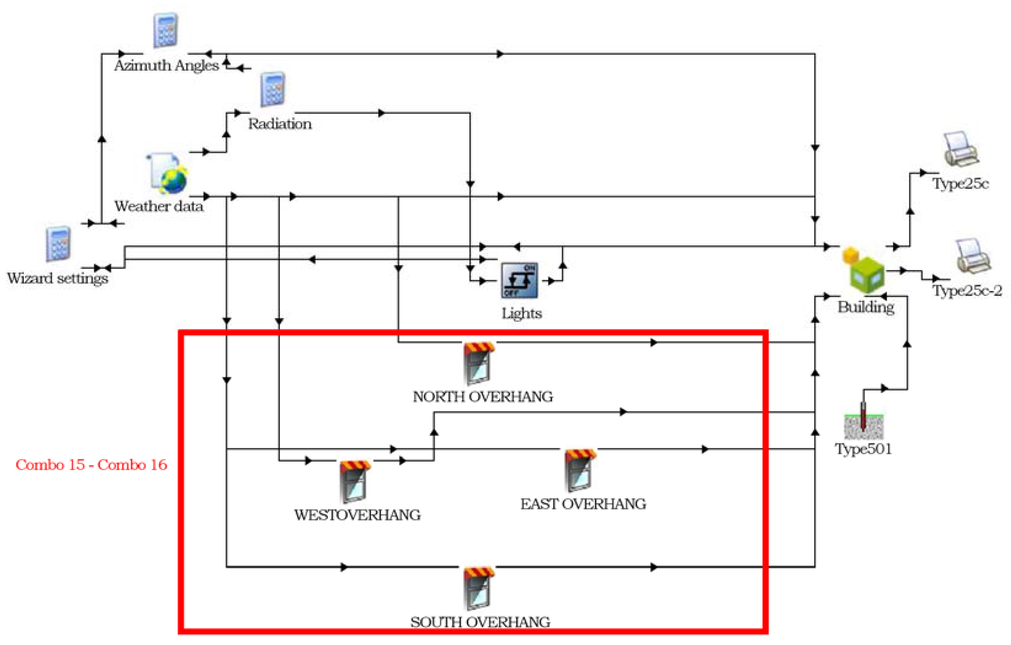
This study has been developed using several Types, among them:
  • Building (Type 56) contains information on the building envelope; i.e., orientation of walls, material properties, stratigraphy, floor and roof, windows properties and thermal loads;
  • Soil characteristics (Type 501);
  • Overhangs (Type 34) reports information on shading elements for each orientation (North overhang, West overhang, East overhang, South overhang);
  • Weather data (Type 15) includes the weather data location. To set up the model, Types must be connected in a logical way as shown in Figure 2.
There are many links among the Types, for example, the Type related to the building is linked both to the weather data, through the measurement of the dry bulb temperature, and to the Type related to the soil through the calculation of the soil temperatures at a chosen depth. The Type related to the overhangs receives inputs from the weather data regarding zenith, azimuth and solar radiation. It also provides the angle of incidence, the incident radiation and the radiation beam on the receiver to the building.
As regards radiation models, for zones with an ordinary facade of punched windows, the increased level of detail has a low impact on the results but increases input effort and computing time. It is recommended to select detail modes only if necessary and, therefore, the simulation has been set as follows:
-
Beam radiation distribution—standard mode. Userdefined distribution factors for surfaces so called GEOSURF values are applied. The value of GEOSURF represents the fraction of the total entering direct solar radiation that strikes the surface.
-
Diffuse radiation distribution—standard mode. The standard mode is based on aborption-transmission weighted area ratios for all surfaces of a zone.
-
Longwave radiation exchange of surfaces within a zone—standard mode. The standard mode is based on the starnode approach. No user defined emissivities of inside surfaces nor radiation exchange over more than one airnode can be taken into account.

2.3. Envelope Optimization Steps

The building prototype has been modelled in every possible orientation and for a period of one year. As shown in Table 1, the optimization process can be divided into eight steps, starting from the external wall optimization and ending with the internal heat loads assessment. Every step in the optimization process allows a deeper understanding of the impact of each component on the thermal behaviour of the building. In particular, the steps coloured in green (STEP 1–3) investigate a completely sealed building. For example, the first step shows how the thermal characteristics of the different walls affect the TOP inside the building. It is possible to understand how the capacitive or resistive behaviour of the walls allows maintaining the internal comfort when stationary transmittance, mass and thickness are constant. This is an extreme limit case. The hypothesis is to understand the behaviour of a disused building, with windows completely closed. For this reason, the internal gains were not considered. The goal of this choice is to analyse the conditions within the environment, in terms of Operative Temperature, considering only the opaque envelope.
The steps highlighted with blue colour consider the presence of glazed elements. In this case the building is considered without users. The hypothesis refers to a building with windows, but when users are not in the house, for this reason the internal gains are not considered.
The last one is marked with red colour and present the estimation of the internal heat loads, considering the impact on the TOP due by the presence of users in the building.
Table 2 summarizes the design options considered for each evaluated component: walls, ground floor, windows, roof absorbance, shading, and internal heat gains. As regards the windows, this study considers the position, the size and the window type. Combining the different design options, a total of 17 combinations have been obtained.
As a final step, the optimized solution is evaluated considering the internal gains, using the values reported in Table 3.

2.3.1. External Walls Selection

The first optimization step relates to the investigation of the behaviour of different external walls types.
The EN ISO 13786 [63] has been used for the calculation of the thermal behaviour of the building components.
Table 4 reports the thermo-physical properties of the wall building materials considered as input data in the modelling. The main material parameters considered are: thermal conductivity, specific heat capacity, density and layer thickness.
Table 5 shows the stratigraphy and thermal properties of the five modelled walls (W1, W2, W3, W4 and W5) that correspond to five building configurations (Combo 1–5).
To associate the complex amplitude of temperature and heat flow rate at the external side with the same at the internal side, the heat transfer matrix Z, described in the EN ISO 13786:2008, has been used.
High-efficient buildings designed for cold climates use multi-layered walls characterized by low steady thermal transmittance (U), using insulating materials with low density and high thickness. This permits to keep down the heating costs in cold winters, where the main requirement is the preservation of internal heat, but it is not convenient to handle in a natural way the other thermal loads. These highly insulating techniques are indicated for heating costs in cold winters, which prevail over summer cooling costs, because the main requirement in winter is the accumulation and preservation of internal heat.
The five walls have been obtained by the arrangement of the materials shown in Table 4 (polystyrene, brick and tuff). These are divided into three layers organized differently, for a total thickness of 38 cm. This choice has led to a definition of five walls of the same thickness (d) and steady thermal transmittance (U). The plaster layer has not been included. The mass value (Ms) is very high to allow the wall to act as a heat storage tank.
The dynamic properties have been shown in order to highlight the dynamic behaviour of the wall.
Low thermal admittance result in overheating/cooling down phenomena.
The areal heat capacity (k) has a remarkable effect on the decrease of the summer peaks, thus reducing the possibility of internal overheating. High heat capacity will also imply a greater capacity to store heat, with the same temperature shifts. Low values of the decrement factor (fd), high values of inside thermal areal capacity (k) and high values in the time shift of periodic thermal transmittance lead to a better characteristic of the walls in the diminishing of the effects of external thermal stress during summertime.
To achieve warmer internal temperatures during night hours, the time shift must be such that the daytime temperature peaks are delayed during night hours towards the building internal side. Low values of the decrement factor and high values of internal areal heat capacity and high values in the time shift of periodic thermal transmittance designate the best wall configuration when the aim is to decrease the effects of external thermal loads during summertime.
At this first optimization step, all the building configurations have neither windows nor ground floor insulation. The solar absorbance of the roof is set at 0.5.
Investigating the behaviour of the operative air temperature for the five building combinations, the best performing wall assessed at this stage is included in the following simulation steps according to the sequential search technique previously described.

2.3.2. Slab on Ground Floor Evaluation

After identifying the best performing wall option, ground floor configurations have been considered. The ground floor is a key element for thermal loads mitigation in a warm climate. This step aims to investigate if a capacitive behaviour of the slab on ground floor is preferable to a resistive behaviour. This can positively influence the performance of the whole building and permits to use the floor for heat storage reservoir. Table 4 lists the thermo-physical properties of the selected options of ground floor materials. Table 6 shows the two ground floor stratigraphies adopted in the configurations: insulated ground floor (IGF) (Combo 4) and not insulated ground floor (NIGF) (Combo 6). The two options have been simulated and compared.
As in the previous step, there are no windows in the building prototype at this stage. This choice aims to reduce the number of variables that impact the investigated options of this step and the linked thermal behaviour. The solar absorbance of the roof is still fixed at a value of 0.5.

2.3.3. Analysis of the Roof Solar Absorbance

At this stage, the envelope includes the walls chosen in the first step and the ground floor selected at the second step. An important aspect to be considered is the temperature rise of the surfaces directly radiated from the sun. This phenomenon causes internal discomfort and higher energy consumption. The use of thermo-reflective materials allows to limit the air temperature increase occurring at the surfaces. This optimization step aims to highlight how the roof solar absorbance changes the air temperature inside the building. Three configurations have been considered: Combo 6, Combo 7 and Combo 8 characterized by a solar absorbance of 0.5, 0.3 and 0.7, respectively. The windows are not yet included in the building prototype. Table 2 shows the combinations in detail.

2.3.4. Evaluation of the Windows Position

Once the opaque envelope has been optimized during the previous steps, the study has been now directed at the analysis of the windows. Windows are considered the weakest element of the envelope in terms of heat losses, solar gains and thermal bridges [64,65].
As shown in Figure 3, two possible windows positions have been evaluated in this study.
A correct placement of the windows effectively improves the thermal performance of the building. This step evaluates the operative air temperature behaviour for the two combinations, considering all building thermal zones orientations. The window properties are reported in Table 7. The comparison has been carried out between Combo 9 and Combo 10 using the G1 window type.

2.3.5. Sizing of Windows

After determining the best window position, this optimization step aims at finding the most suitable window size. According to the Italian building codes, the opening area of a building should not be less than 1/8 of the floor surface. It has been noted that, with the same window surface, the amount of light varies according with the type of window. At this stage, all the previous best performing options of the analysed components up to this optimization step have been implemented. The operative air temperature has been plotted for an opening area equal to: 1/8 of the floor surface (Combo 10), 1/7 of the floor surface (Combo 11) and 1/9 of the floor surface (Combo 12).

2.3.6. Study of the Impact of Window Types

This optimization steps investigates the behaviour of different windows types. Table 7 lists the thermo-physical properties of the window options (G1, G2 and G3) selected for the modelling. These are characterized by different values of transmittance (U) for frame (Uf) and glass (Ug), and solar factor (g). The considered stratigraphy is: 6/16/6 with argon insulation (Combo 10), 4/16/4 with argon insulation (Combo 13) and 4/8/4/8/4 with krypton insulation (Combo 14). Table 2 summarizes the configurations compared: Combo 10, Combo 13 and Combo 14.

2.3.7. Assessment of Shading

This step focus on the impact of shading devices on the building thermal behaviour. The shading is designed as an overhang of 5 m around the entire building perimeter. This choice comes from the need to evaluate how important the influence of shadows can be. The optimized configuration obtained up to the previous step, has been compared with another configuration (Combo 15) modelled considering a horizontal overhang shading that covers the entire building with an overhang of 5 m. An extreme shading case has been chosen to investigate the maximum influence on the thermal behaviour that shading can give. Both configurations have windows placed in position 2, as shown in Table 2.

2.3.8. Estimation of the Internal Heat Loads

The evaluated loads are related to:
  • a family of four people within the building;
  • a load of 5 W/m2 due to the use of appliances from 8:00 to 20:00;
  • a load of 3 W/m2 due to the use of appliances from 20:00 to 8:00.
This optimization step compares Combo 10, Combo 15 Combo 16 and Combo 17. As shown in Table 2, Combo 10 and Combo 15, that differ only for the absence or presence of shading devices, are used to evaluate the impact of internal loads in terms of operative air temperature in the building. Table 3 shows the internal gains considered at this step (occupants, lighting and equipment gains) that are incorporated in Combo 16 and Combo 17.

2.3.9. Ground boundary conditions

The ground data used in the simulations are reported in Table 8.

2.3.10. Comfort Evaluation

In the final step of the optimization, comfort conditions inside the building prototype have been evaluated using the PMV–PPD models. It represents the votes of a group of persons on a series of thermal point and it is strongly influence d by the variation of the air temperature, relative humidity, mean radiant temperature, air velocity, the metabolic rate and clothing insulation. The following values have been assumed to derive the end user ratings:
  • Clothing factor = 1 (CLO);
  • Metabolic rate = 1.2 (MET);
  • Relative air velocity = 0.15 m/s;
  • Relative humidity value = 50%.

3. Results and Discussion

The building thermal behaviour has been studied at each optimization step in summer and winter conditions (Table 9 and Table 10).
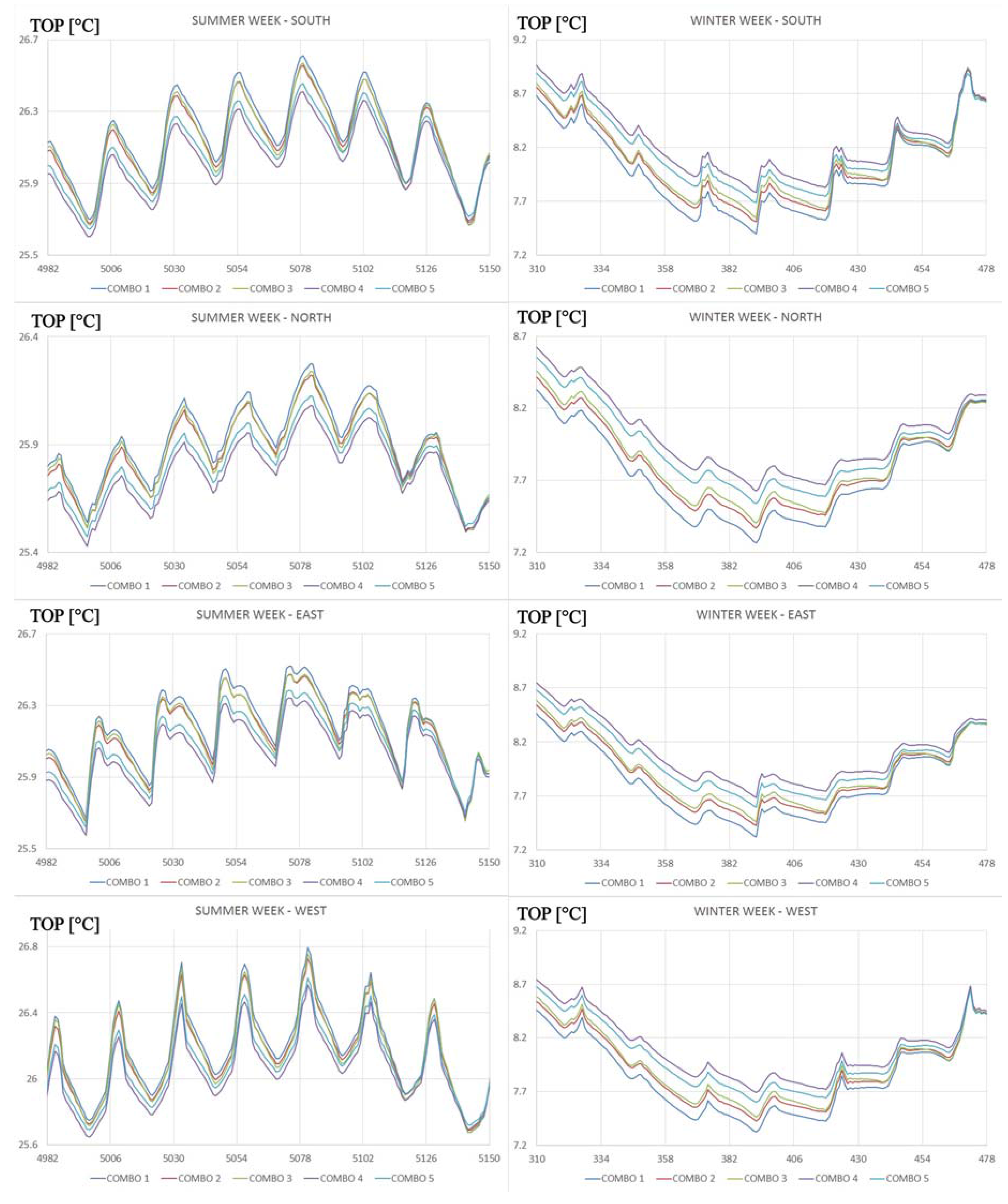
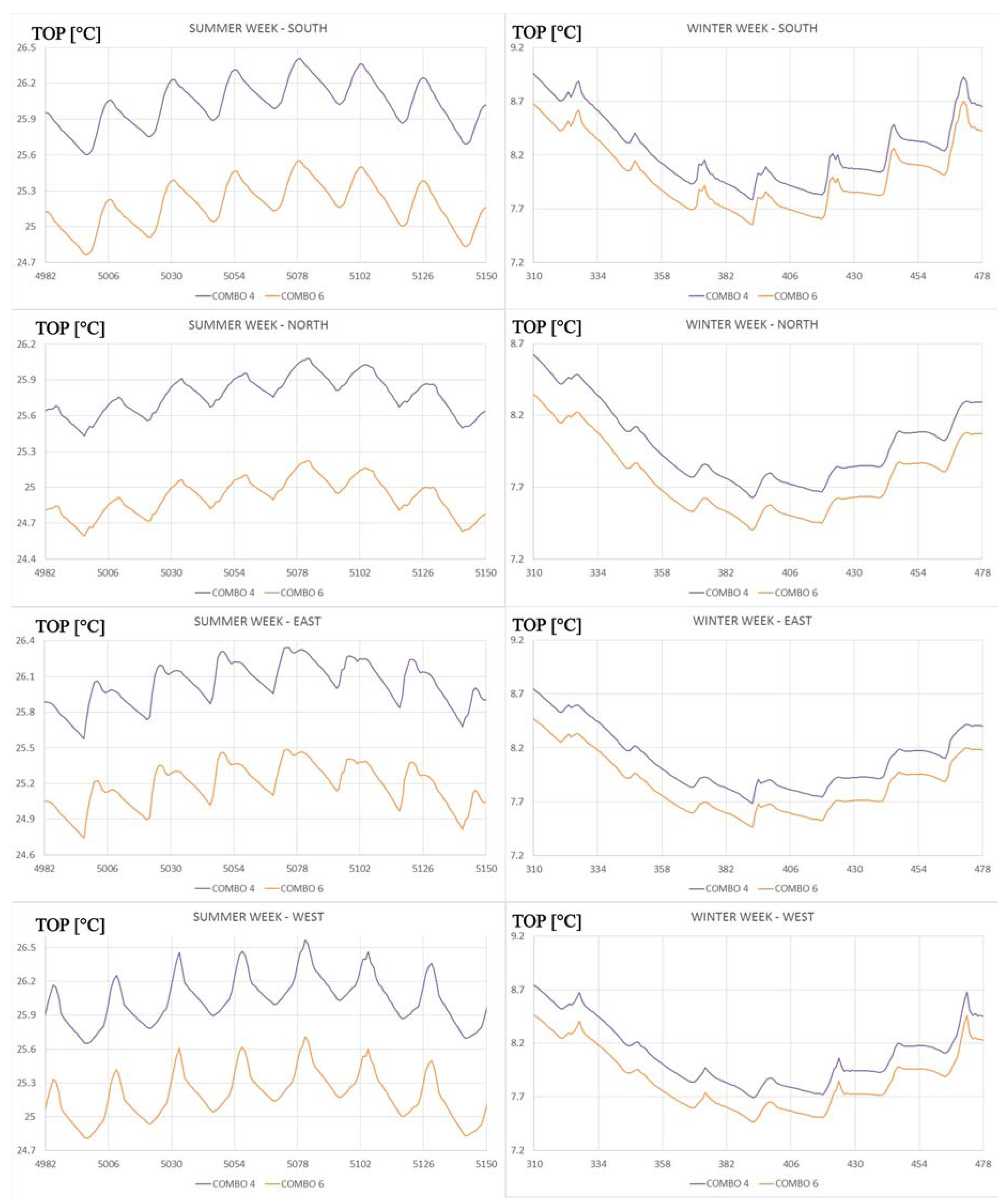
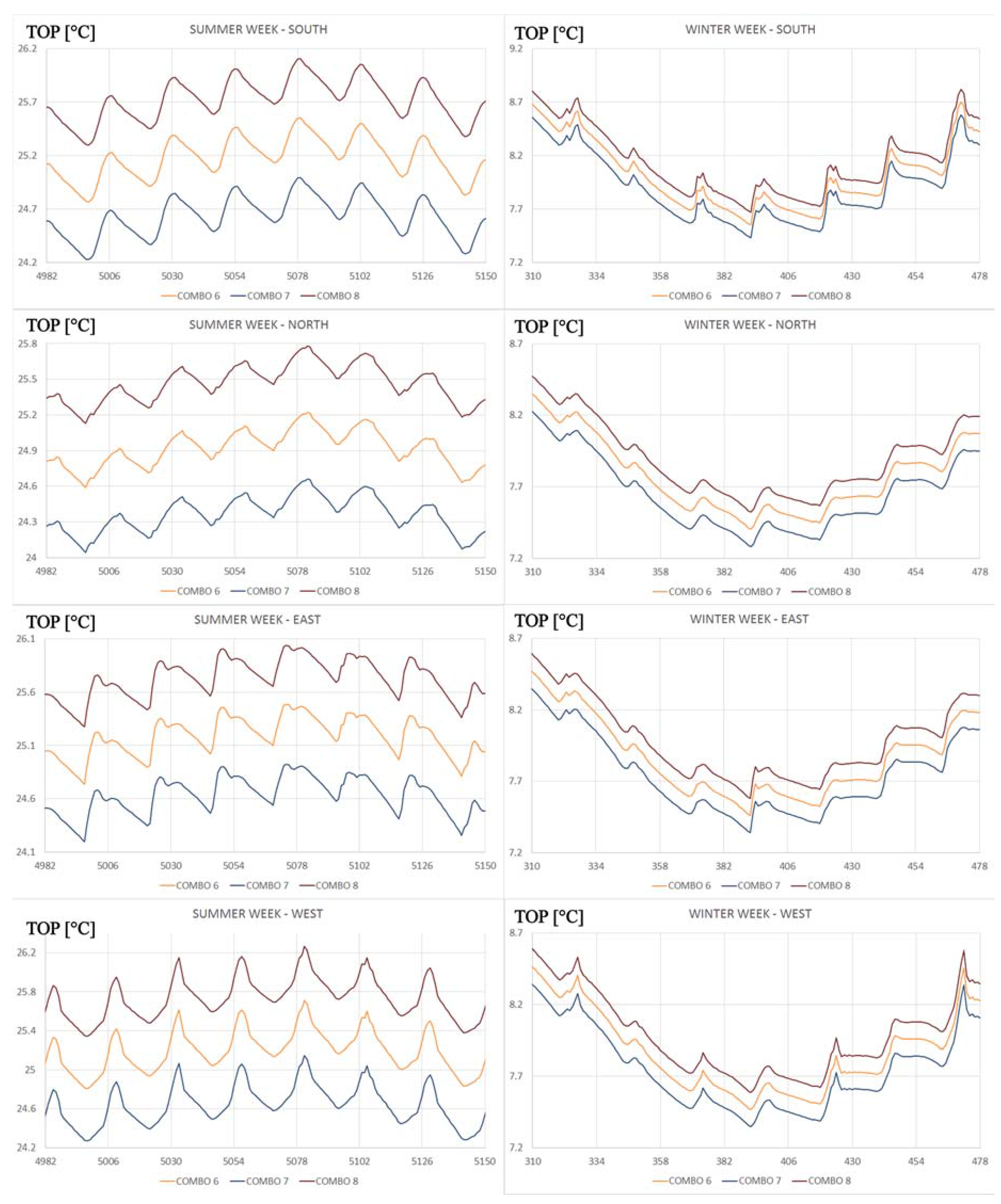
The obtained data have been plotted on graphs that report the internal temperature (°C) in function of time (h). Figure 4, Figure 5, Figure 6, Figure 7, Figure 8 and Figure 9 show the operative air temperature (TOP) at each simulation step, considering the week having the highest and lowest temperature peaks in summer and winter.

3.1. External Walls

The operative air temperature trends have been studied for each simulated wall configuration (Combo 1 to 5). As shown in Figure 4, the wall stratigraphy of Combo 4 gives a higher internal temperature in winter, compared to the other wall configurations. The Combo 4 shows the best performances also in summer time, for all orientations. The selection of the best wall option starts from the observation that walls in a warm climate should have a high internal areal heat capacity to improve the heat storage and cope with external temperature variations that occur in summer. Therefore, the configuration with walls able to reduce and delay as much as possible temperature peaks towards the walls inner side are favoured. The time shift should be sufficient to transport temperature peaks towards the inner wall surface during nighttime, when the external air temperature is lower. Considering these aspects, all simulated configurations present an adequate time shift. The lowest value is equal to 13.30 h (Combo 1) and the highest is 15.15 h (Combo 5).
Looking at the operative air temperature trend in the five combinations (Combo 1 to 5), it can be noticed how a higher internal heat capacity ensures a more comfortable indoor temperature, both in summer and winter, when comparing configurations with the same external heat capacity, phase shift and transmittance. This is the case of the combinations Combo 1 (having W1) and Combo 2 (having wall W2), where the last one shows a better behaviour. A lower external areal heat capacity ensures a more comfortable indoor temperature both in summer and winter, when comparing the configuration with the same internal areal heat capacity, phase shift and transmittance. Table 9 and Table 10 show in details the peak values of the TOP and the graphs are shown in Figure 4.
The Combo 1 and Combo 4 outline the limit of the TOP trend both in summer and winter time. As regards the summer, the difference in terms of TOP peak in the SW room, considered the most critical orientation, is 0.33 °C, while the minimum difference is at East for a value of 0.17 °C. For this reason, the application of W1 and W4 on the East side has not much difference.
As regard the winter time, the difference of Temperature between Combo 1 and Combo 4 in the SW and SE rooms is 0.42 °C, i.e., the highest value, confirming that the Combo 4 guarantees higher Temperature compared with the Combo 1. In all orientations, it is confirmed the better behaviour of Combo 4.
Table 11 and Table 12 point out the summer and winter peaks of the TOP considering the different properties of the walls. The relation between each parameter and the TOP has been shown.

3.2. Slab on Ground Floor

It is noteworthy observing that the operative air temperature decreases in summer in the configuration that does not have the insulating layer in the floor (Combo 6).
The trends reported in Figure 5 show that both in summer and winter the Combo 4 guarantees always higher values of TOP. This is positive for the winter time, but inconvenient for the summer time.
From the graphs in Figure 5, a slight temperature decrease in winter can be observed. Comparing the operative air temperature of Combo 6 (without insulation, NIGF) and Combo 4 (having insulation, IGF) in summer, it can be noticed that each room has a temperature decrease up to 0.8 °C.
The hottest area of the building, having a South-West orientation, goes from a peak of 26.91 °C in Combo 4 to a peak of 26.11 °C in Combo 6. In winter, the absence of floor insulation causes a 0.22 °C decrease of the minimum temperature in each room. In the Northeast part of the building, the peak falls from 7.52 °C in Combo 4 to 7.31 °C in Combo 6.
The Central room in the summer season sees a reduction of the Temperature peak equal to 0.92 °C replacing Combo 4 with Combo 6. In summer, the difference between the two cases is more different than in winter season, in particular in the summer the best trend is described by the Combo 6 and in winter by the Combo 4. The difference of the peaks between Combo 4 and Combo 6 in summer fluctuate between 0.79 °C and 0.92 °C, while in winter are much more stable and reduced (0.21 °C and 0.23 °C). This confirms that in summer the contribution of the ground has a positive influence on the TOP, privileging the solution without the insulating layer (Combo 6), in winter in preferable to have the insulation layer, but considering the little difference in the winter time and in order to avoid the risk of the overheating in the summer season the Combo 6 has been selected for the subsequent analysis.

3.3. Roof Absorbance

The reduction of the solar absorption coefficient of the roof results in a decrease of the indoor operative air temperature. Comparing varying values of the absorption coefficient, equal to 0.3 (Combo 7), 0.5 (Combo 6) and 0.7 (Combo 8), results show that the most performing configuration is Combo 7.
The trends reported in Figure 6 show that both in summer and winter the trends marked with red, orange and blue colours, keep the same disposition. Proceeding from the trend with a higher temperature towards the lower temperature trend we find: Combo 4, Combo 6 and Combo 7, both for summer and winter season. Combo 8 guarantees always higher values of TOP, making it profitable for the winter season. On the other hand, a greater impact on the reduction of temperature is evident in the warm season with the Combo 7.
A decrease of the coefficient from 0.7 (Combo 8) to 0.3 (Combo 7) leads to a 1.11 °C temperature reduction in the thermal zones oriented East, South, North and West. In the other building orientations (Northwest, Northeast, Southwest, Southeast), the value is never inferior to 1 °C. In the South-West orientation, the maximum temperature goes from 26.62 °C (Combo 8) to a maximum of 25.60 °C (Combo 7). In winter, the minimum peaks of Combo 7 present a 0.24 °C decrease in the North zone, while Combo 6 and Combo 7 have a temperature decrease up to 0.56 °C in summer and 0.12 °C in winter. Figure 6 shows the weekly trend of this behaviour. Therefore, Combo 7, having a roof absorbance of 0.3, has been selected at this optimization step.

3.4. Windows Position

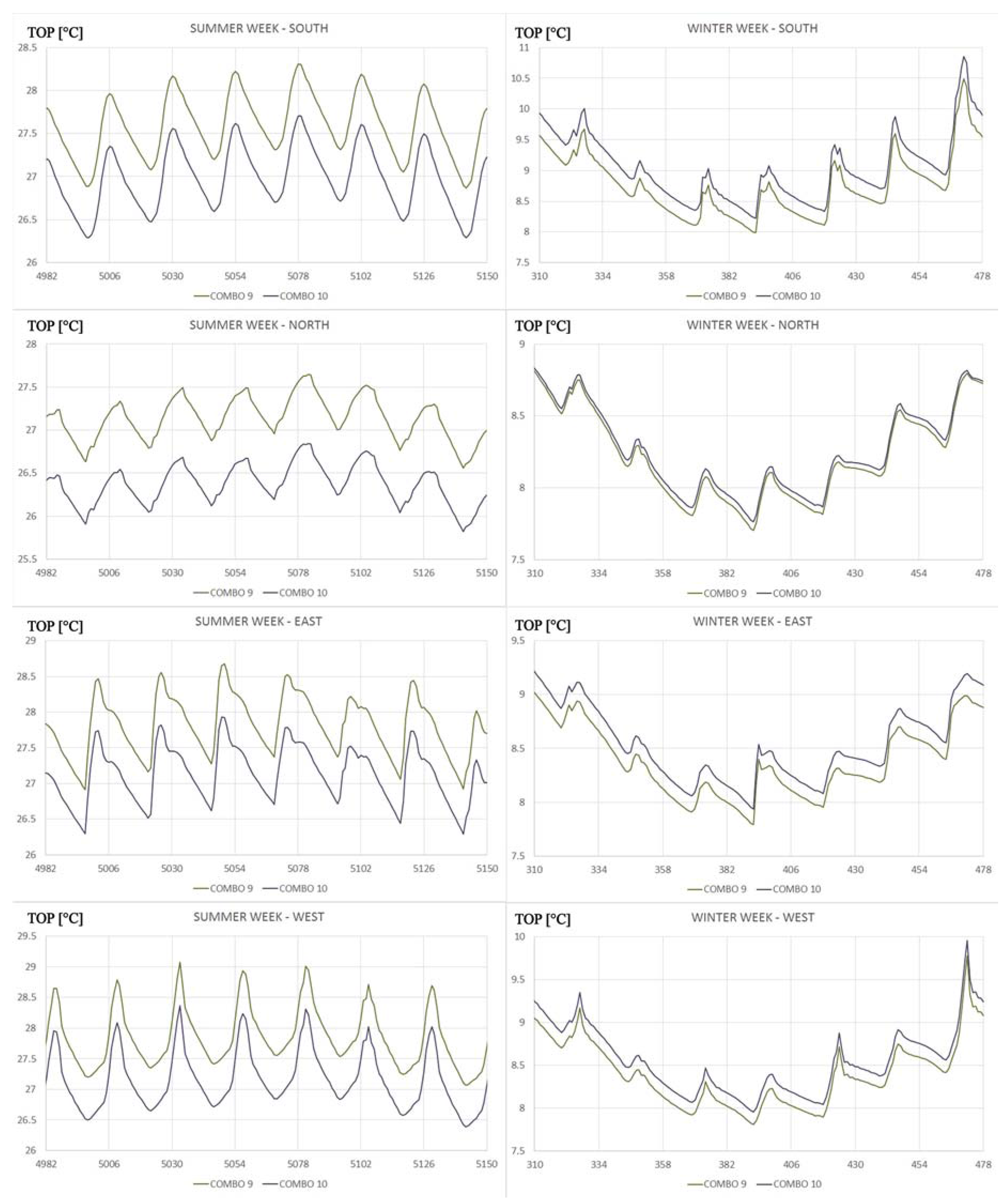
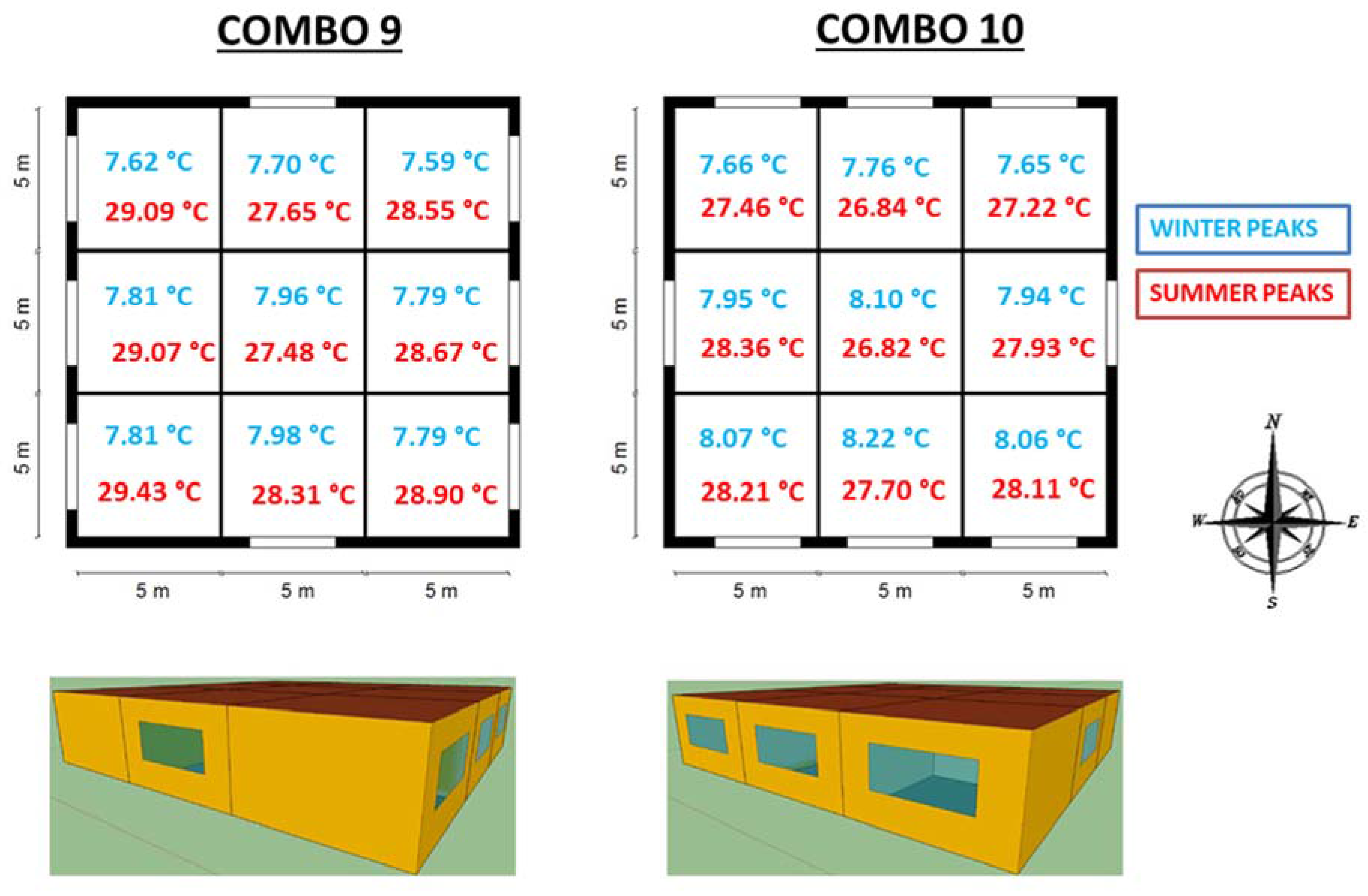
This step evaluates two different window positions. As shown in Figure 3, Combo 9 has the first position and Combo 10 the second. The window area is equal to 1/8 of the overall room surface. A model of 6/16/6 glass with argon in the cavity and an aluminium frame is used for each window. Results show that a lower annual temperature is obtained with the second position (Combo 10).
The trends reported in Figure 7 show that Combo 10 guarantees low values of TOP in summer and high values of TOP in winter.
In Figure 10, the comparison between the peak values in summer and winter for each orientation has been highlighted. Combo 9 and Combo 10 are useful to estimate the impact of the position of the windows on the TOP trend. The choice to divide the module into nine equal sized zones derives from the need to study the TOP trend for each orientation and to address different and specific interventions, such us an optimized placement of the windows.
Comparing Combo 9 and 10 in terms of operative air temperature, a 0.60 °C reduction of the maximum summer peak is achieved in the South building area with Combo 10. About the Northwest room, a 1.64 °C reduction of the summer peak and 0.04 °C of the minimum winter peak are obtained, while the Southeast room a 0.27 °C reduction of the minimum winter peak is reached with this window configuration. Comparing Combo 10 to the best configuration obtained without windows (Combo 7), an increase of the maximum summer temperature can be found, ranging from 2.17 °C (North-West and North-East) to 3.21 °C (West). The winter minimum has a favourable increase in terms of operative air temperature, ranging from 0.45 °C in the Northeast orientation to 0.78 °C in the South (Figure 7). Therefore, the window position 2 (Combo 10) appears to have a better performance and it has been selected for the next simulations. Summarizing the selected options until this step, there are: window area equal to 1/8 of the room surface, roof absorption coefficient of 0.3, W4 as walls type and absence of the insulating layer in the ground floor stratigraphy. All these options are incorporated in Combo 10 as foreseen by the sequential search technique.

3.5. Windows Sizing

This optimization step considers different window surfaces and their impact on the indoor temperature, starting from the best configuration obtained at the previous step (Combo 10). The considered ratio between the vertical area of the glass surface and the horizontal surface area of a single room are: 1/7 (Combo 11), 1/8 (Combo 10), and 1/9 (Combo 12). Considering that each room has a 5 m2 surface area, the following dimensions have been evaluated: 4.21 m2 (for a ratio of 1/7), 3.68 m2 (for a ratio of 1/8) and 3.27 m2 (for a ratio of 1/9).
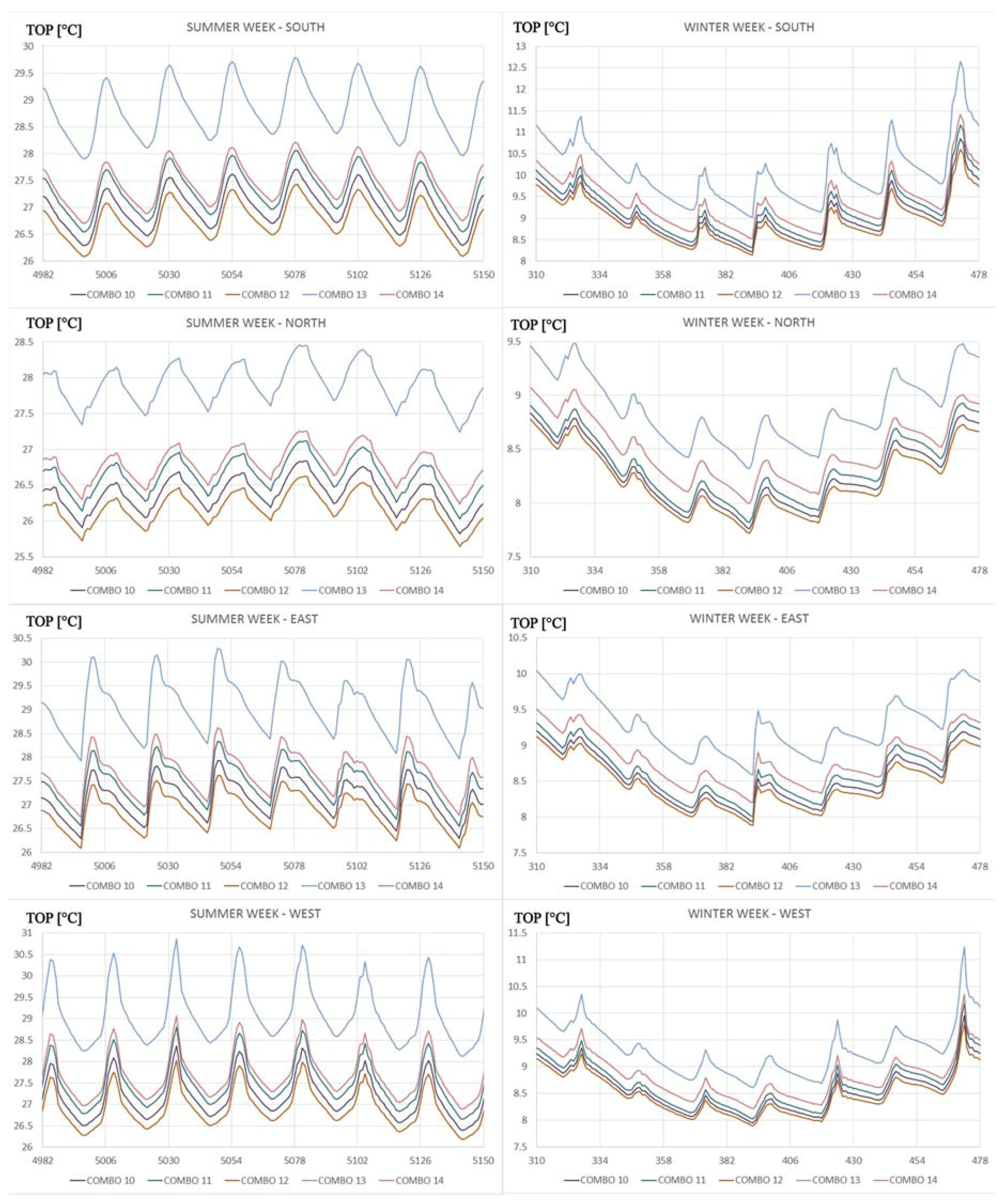
The trends reported in Figure 8 show that both in summer and winter the trends marked with purple blue and orange colours, keep the same disposition. Proceeding from the trend with a higher temperature towards the lower temperature trend we find: Combo 11, Combo 10 and Combo 14, both for summer and winter season. Combo 11 guarantees always higher values of TOP, making it profitable for the winter season. On the other hand, a greater impact on the reduction of temperature is evident in the warm season with the Combo 12.
The ratio equal to 1/9 shows the best behaviour in terms of operative air temperature in summer. Therefore, the decrease of the window area involves a larger reduction of summer maximum peaks. A ratio of 1/9 (Combo 12) compared to a ratio of 1/7 (Combo 11) has a decrease of the maximum summer temperature, which ranges from about 0.5 °C (in the rooms oriented North and Northeast) to 0.78 °C (West). As regards the winter minimum, there is a reduction ranging from 0.09 °C in the room located Northeast to 0.17 °C in the Northwest side.
Comparing a ratio of 1/8 (Combo 10) to a ratio of 1/7 (Combo 11), a maximum summer temperature decreases from about 0.28 °C (in North and North-East) to 0.44 °C (to the West) can be found. For the winter minimum, a reduction from 0.05 °C (NE and NW) to 0.09 °C can be found in the South oriented room.
To meet the minimum lighting required by the Italian law, the analysis of the following optimization steps has been carried out considering a ratio of 1/8. The 1/8 ratio shows a peak ranging from 26.85 °C (North) to 28.37 °C (West), and a minimum peak that goes from 7.65 °C (North-East) to 8.22 °C (South).

3.6. Window Types

Starting from the configuration selected at the previous step (Combo 10), the thermal behaviour of the building has been studied for a varying stratigraphy of the window glass area.
Figure 8 shows the trend of the operative air temperature, while Table 9 and Table 10 report the summer and winter peaks. Results show the advantages of double glass 6/16/6 with argon (g = 0.333), especially in summer conditions. Looking at the winter trend, it does not seem convenient to use double windows 4/16/4 (g = 0.589) glass with argon. An intermediate response is obtained by 4/8/4/8/4 windows triple glass with krypton in the cavity (g = 407).
Combo 10 compared to Combo 13 causes a decrease of the maximum summer temperature that ranges from 1.6 °C (Northeast) to 2.5 °C (West). For the winter minimum, the reduction goes from 0.52 °C to 0.8 °C Northeast to South.
Comparing Combo 14 with Combo 13, a decrease of the maximum summer temperature from 1.2 °C (North) to 1.8 °C (West) is found. As regards winter minimum peaks, there is a reduction that goes from 0.3 °C (Northeast) to 0.5 °C (South).
Analysing the warmest thermal zone, i.e., the room located to the West, it can be noted that maximum summer peaks are equal to 28.37 °C, 29.06 °C, 30.87 °C, respectively for Combo 10, Combo 14 and Combo 13. Instead, winter minimum peaks are equal to 7.95 °C, 8.21 °C, and 8.60 °C respectively for Combo 10, Combo 14 and Combo 13.
Data show the better behaviour of the window stratigraphy 4-16-4 argon in winter, but a better behaviour is obtained in summer with the window stratigraphy 6/16/6 argon. Therefore, the best configuration at this step remains Combo 10, having a 6/16/6 glass with argon in the cavity and an aluminium frame.

3.7. Shading

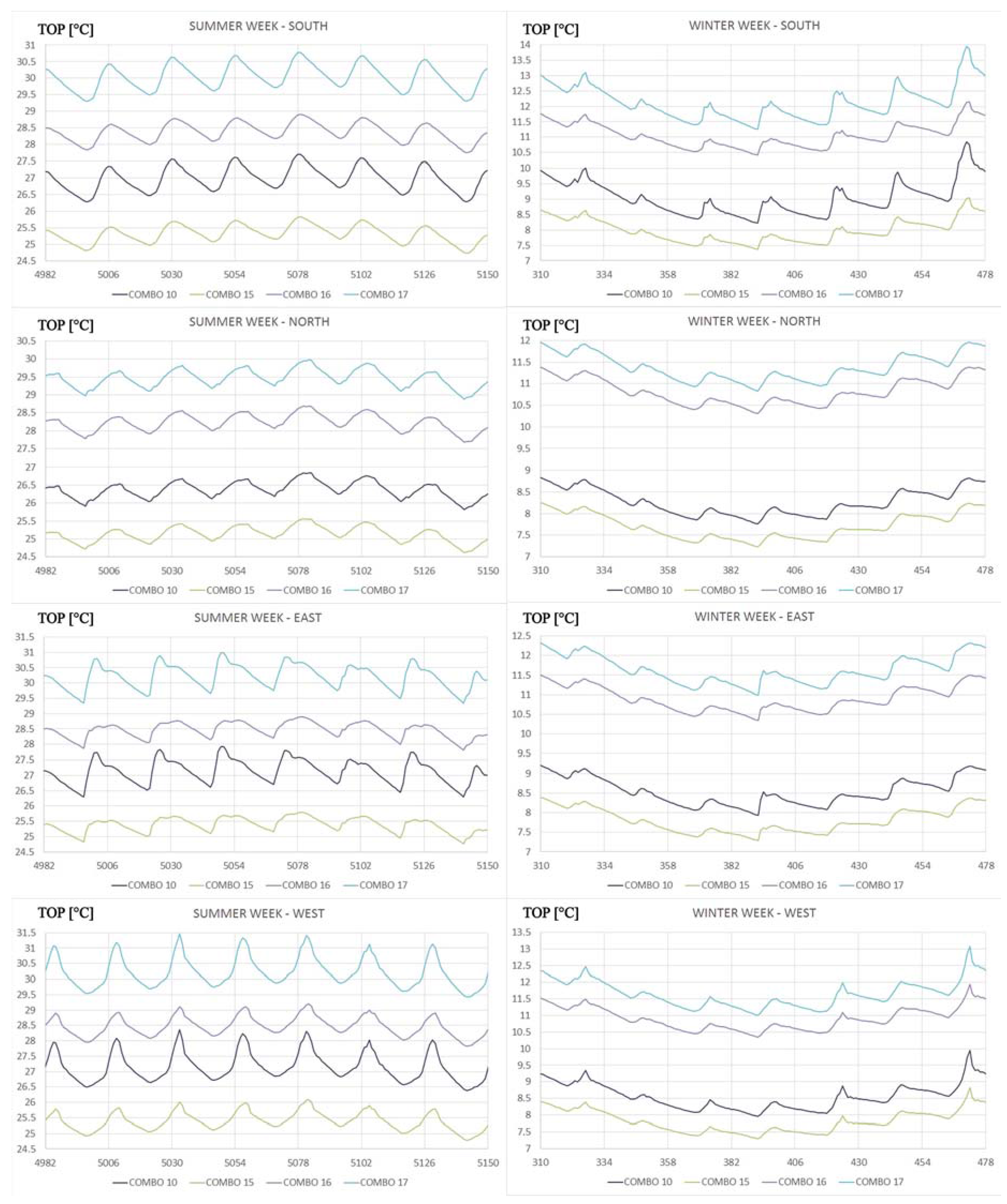
This step evaluates the thermal building behaviour in presence (Combo 15) and absence (Combo 10) of shading measures (Figure 9). The evaluation of the shading is considered the extreme case of a building totally shaded, then the limit level of temperature achievable with an estimated total shading of all the rooms.
The presence of shading systems implies a decrease of the maximum summer temperature, which ranges from 1.28 °C (North) to 2.27 °C (West). However, in winter there is a reduction of the minimum peak that goes from 0.51 °C (Northwest) to 0.83 °C (South). In the room oriented to West (considered to be the warmest room in summer, with no shading), the operative air temperature goes from 28.37 °C to 26.10 °C in summer, and from 7.95 °C to 7.30 °C in winter. In the Northeast room (highlighted as coldest room in the winter, with no shading) the values of the internal temperature range from 27.22 °C to 25.90 °C in summer, and from 7.65 °C to 7.15 °C in winter.

3.8. Internal Heat Loads

This optimization step compares Combo 10, Combo 15, Combo 16, and Combo 17 to evaluate internal heat loads.
The inclusion of internal gains has resulted in an increase of the internal operating temperature both in summer and winter. In summer, the maximum peak including thermal loads increases from 2.84 °C (Southeast) to 3.12 °C (North). In winter, the minimum peak increased from 2.8 °C (Southeast and Southwest) to 3.07 °C (North). The room located Southwest (the warmest room in summer with no loads and presence of shading) has a temperature from 26.36 °C to 29.22 °C in summer, and from 7.27 °C to 10.07 °C in winter. On the other hand, the internal temperature of the Northeast oriented room (the coldest room in winter with no loads and presence of shading) goes from 25.90 °C to 28.80 °C in summer, and from 7.15 °C to 10 °C in winter.
The comparison between Combo 10 and Combo 17 shows that the inclusion of internal heat causes an increase of about 3 °C of the operative air temperature both in summer and in winter, in all rooms. As regards the area oriented to West, in absence of internal thermal loads (Combo 10), the maximum peak of summer reaches a value equal to 28.37 °C. The temperature increases up to 31.47 °C with internal heat loads (Combo 17). In winter, the TOP has a minimum peak in absence of internal thermal loads (Combo 10) equal to 7.95 °C, which increases up to 11 °C with internal thermal loads (Combo 17). The coldest area in winter (Northeast) shows a summer maximum peak with no internal thermal loads (Combo 10) equal to 27.22 °C, which increases up to 30.13 °C in Combo 17. In winter, the TOP shows a minimum peak in Combo 10 equal to 7.65 °C, which increases up to 10.51 °C in Combo 17. The comparison between Combo 16 Combo 17 highlights that the absence of shading causes an increase of summer maximum temperature peaks ranging from 1.29 °C (North) to 2.26 °C (West). The winter minimum peaks rise from 0.51 °C (NW) to 0.84 °C (South). The West building area, the hottest building zone, reaches a maximum summer peak in case of shading (Combo 16) equal to 29.21 °C, which increases with no shading (Combo 17) up to 31.47 °C. In winter, the TOP has a minimum peak in Combo 16 amounting to 10.35 °C, which increases up to 11 °C in Combo 17. The coldest zone in winter is the Northeast area. From the comparison between Combo 16 and Combo 17, the maximum summer peak in case of shading is equal to 28.81 °C, which increases up to 30.13 °C with no shading. In winter, the TOP has a minimum peak for the Combo 16 equal to 10 °C, which increases up to 10.51 °C in Combo 17.
Table 13 shows in details the trend of the TOP in Combo 17, focusing on the minimum, maximum and middle peaks of temperature considered for the whole year, all room orientations and average values for each month. During August, the TOP ranges between 28.75 °C and 29.5 °C, while in January it is assessed between 12.45 °C and 13.62 °C, according to the rooms orientation.

3.9. PMV and PPD

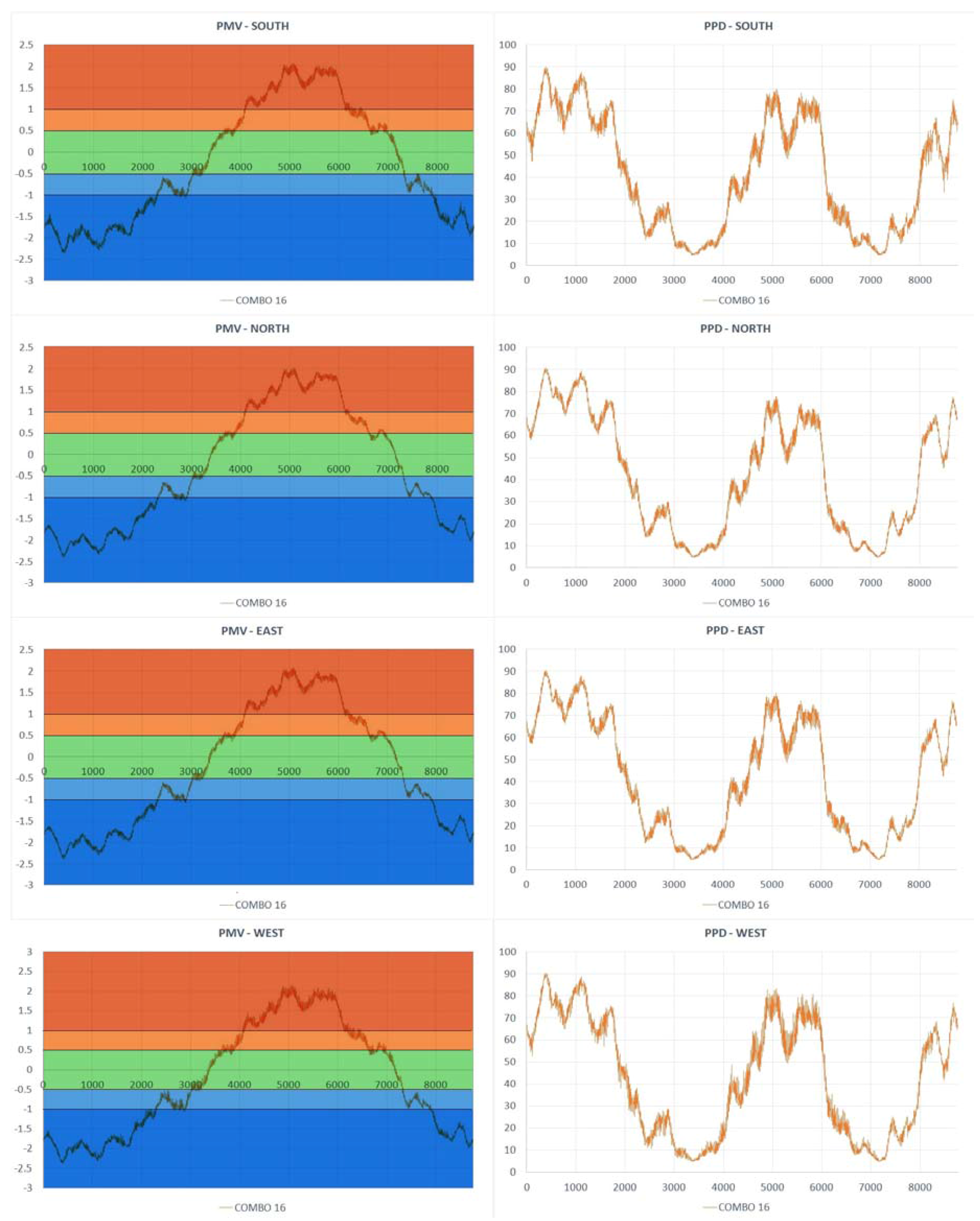
Figure 11 shows the PMV and PPD trends for Combo 16 that resulted the best configuration considering shading and internal gains. The annual PMV and PPD trends are comparable for each room and included within the same range of values. As regards PMV, the annual trend ranged of approximately between −2.4 (in winter) and +2 (in summer). The PPD reached a peak of 90% dissatisfied in winter and 80% dissatisfied in summer. The most convenient percentage of dissatisfied (equal or minor than 10%) is obtained at the end of spring and early autumn (Figure 10).
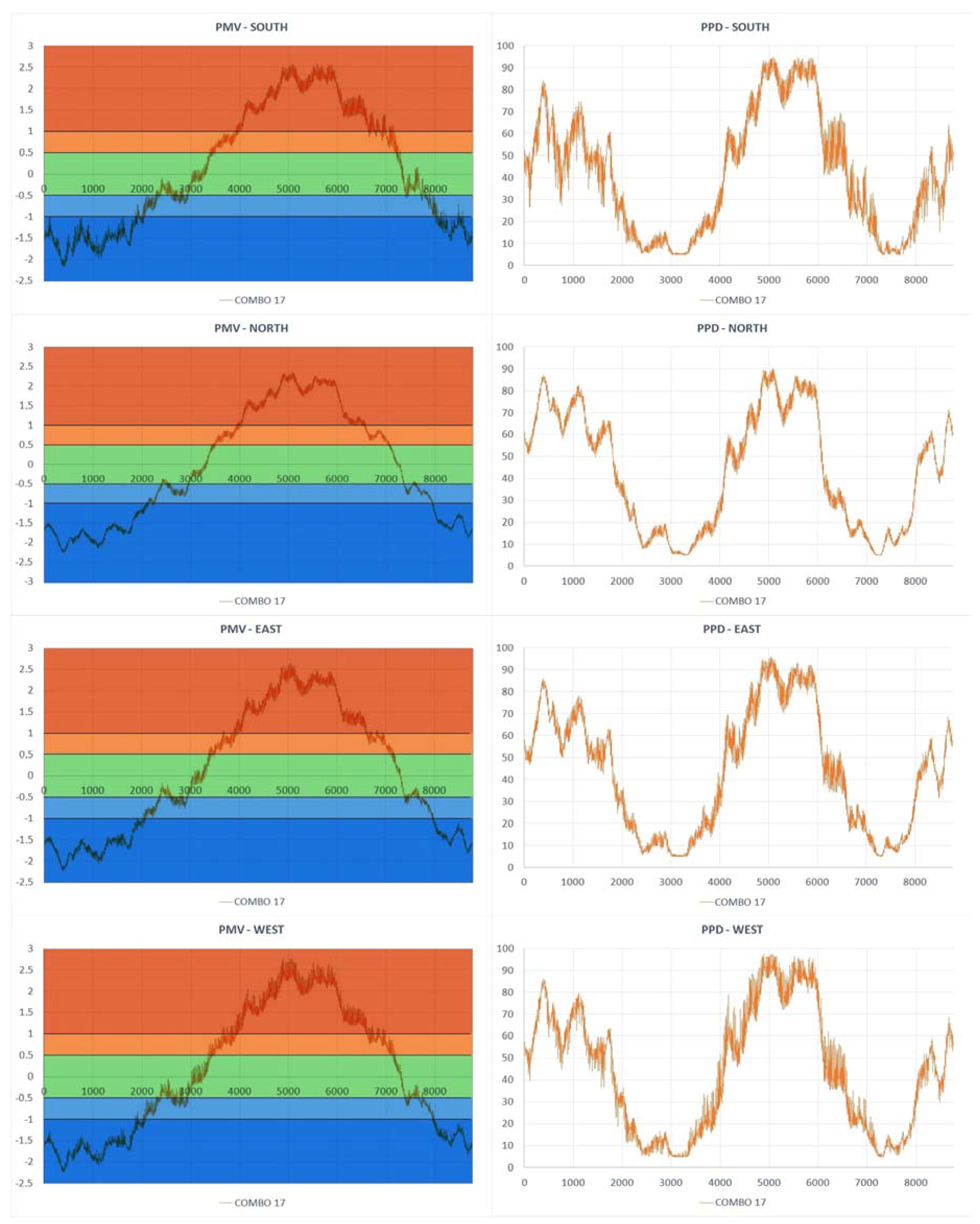
The PMV and PPD trends of Combo 17 are shown in Figure 12. Combo 17 has the best envelope configuration design obtained considering internal gains and no shading. In this configuration, the PMV trend reaches the minimum peaks in correspondence of the winter period. Values are similar in each room and approximately equal to −2.2. In summer, the highest values are equal to: 2.6 in the South and East building orientations, 2.3 in the North and 2.8 in the West. The percentage of dissatisfied in summer is up to 90% in the North and 97.5% in the West building orientation. In winter, values of 80% have been reached. Only a few time intervals have the PPD equal to or minor 10%.
The last step of this study was the evaluation of the performances of the Combo 17 by applying natural ventilation. Figure 13 shows the annual trend of the TOP highlighting with the blue colour the Combo 17 (as previously defined) and with the green colour the same combination but with the application of natural ventilation having an air exchange rate of 0.5 volume per hour. The graphs show the greatest influence of ventilation during the summer period in terms of overheating, while during the winter the trends are very similar.

4. Conclusions

This paper investigates the thermal behaviour of a building prototype located in a warm climate to optimize its envelope design. With this aim, several design options, organized in different configurations, have been modelled and compared in terms of operative air temperature using a sequential search technique. In the last part of the research, comfort conditions have been evaluated to test if the optimized configurations satisfied the users. Results show how each option can impact the thermal behaviour of the building and how each choice related to the envelope has to be carefully made at the design stage.
Among the evaluated component within the optimization (walls, ground, roof, shading, windows and internal loads) some aspects appeared more critical for the climate under investigation. This study, elaborated for a warm climate, shows that it is not necessary to use extensive insulation thicknesses on the wall to ensure comfort within the environment, thus the attention will be focused not on low steady transmittance values, but it is more effective to maintain high values of internal areal heat capacity, in order to guarantee high massive envelope. External walls with high values of internal areal heat capacity can significantly reduce and delay temperature peaks on the internal side of the building, especially in summer.
In addition, as regards slab-on-ground floor, it has been determined that, for warm climates it is not necessary to have a wide insulating thickness and fall too far below the legal limit does not have a good result at the internal comfort level, as the high risk of overheating. To have a better indoor temperature, a ground floor without insulating layer and a roof with low solar absorbance are preferable.
Once optimized the opaque envelope components related to walls and roof, windows appeared to be relevant within the optimization process. Results show how the simulated window options related to position, size, and type of glass impact the operative air temperature. Low-emissivity glass permits us to reduce the heat loads during the hottest seasons. These elements can provide an improvement of the operative air temperature around 2 °C in summer and a reduction of around 0.5 °C in winter. This suggests the necessity of minimize the window surfaces for a warm climate. The windows analysis shows the importance of the evaluation of the solar transmittance of the window during the design phase, which is very crucial for the window energy performances. The analysis of the selective glazing, characterized by low values of solar factor, shows the better behaviour in summer, while the low emissive glass, with higher values of solar factor results optimal for the winter season. The aim of this study is to reduce the overheating inside the buildings; the minimization of the solar factor (g) leads significant advantages in buildings built in the warm climate.
The paper demonstrated that low attenuation factor values in conjunction with high values of internal areal heat capacity and high values of time shift, are the best envelope options to mitigate the effects of summer external thermal loads, the most critical issue in a warm climate.
The presented methodology appears a useful support for designers in the choice of the best technical measures for reach high efficient buildings also considering the indoor comfort parameters (PMV ad PPD) results.
Further analysis will be carried out in order to optimize the building module showing how internal loads affect the internal operative temperature trend and the comfort within the building.
Future developments of this work relate the optimized envelope and the comfort obtained by a geothermal system, identified as an optimal system solution in a warm climate. Further optimizations studies can be performed considering different building uses and climates. The analysis of the cost optimal of the efficiency measures can be a strong support for the decision-making practices of technicians and designers.

Author Contributions

All authors participated in preparing the research during its phases, such as establishing research design, method and analysis. They discussed together and finalized the analysis results to prepare manuscript accordingly.

Conflicts of Interest

The authors declare no conflict of interest.

Nomenclature

TOPoperative air temperature (°C)
USteady thermal transmittance (W/m2K)
Ymmthermal admittance (W/m2K)
Ymnperiodic thermal transmittance (W/m2K)
cspecific heat capacity (J/kgK)
dthickness of a layer (m)
fddecrement factor
gsolar factor
∆ttime shift: time lead (if positive), or time lag (if negative) (s or h)
Mstotal surface mass (excluding coats) (Kg/m2)
Greek letters
κareal heat capacity (kJ/m2K)
λdesign thermal conductivity(W/m K)
ρdensity (kg/m3)
Subscripts
m,nfor the thermal zones
gglass
fframe
1internal
2external

References

  1. Ruamsuke, K.; Dhakal, S.; Marpaung, C.O.P. Energy and economic impacts of the global climate change policy on Southeast Asian countries: A general equilibrium analysis. Energy 2015, 81, 446–461. [Google Scholar] [CrossRef]
  2. European Commission. Taking Stock of the Europe 2020 Strategy for Smart, Sustainable and Inclusive Growth; European Commission: Brussels, Belgium, 2014. [Google Scholar]
  3. Eurostat. Final Energy Consumption by Sector. 2014. Available online: http://ec.europa.eu/eurostat/data/database (accessed on 8 October 2017).
  4. Li, D.H.W.; Yang, L.; Lam, J.C. Impact of climate change on energy use in the built environment in different climate zones—A review. Energy 2012, 42, 103–112. [Google Scholar] [CrossRef]
  5. D’Agostino, D. Assessment of the progress towards the establishment of definitions of Nearly Zero Energy Buildings (nZEBs) in European Member States. J. Build. Eng. 2015, 1, 20–32. [Google Scholar] [CrossRef]
  6. EU, Directive 2012/27/EU. European Parliament and of the Council of 25 October 2012 on energy efficiency, amending Directives 2009/125/EC and 2010/30/EU and repealing Directives 2004/8/EC and 2006/32/EC. Off. J. Eur. Union 2012, L315/1. [Google Scholar]
  7. EU, Directive 2010/31/EU. European Parliament and of the Council of 19 May 2010 on the Energy Performance of Buildings (recast). Off. J. Eur. Union 2010, 13–35. [Google Scholar]
  8. Yu, J.; Tian, L.; Yang, C.; Xu, X.; Wang, J. Sensitivity analysis of energy performance for high-rise residential envelope in hot summer and cold winter zone of China. Energy Build. 2013, 64, 264–274. [Google Scholar] [CrossRef]
  9. Baglivo, C.; Congedo, P.M. High performance precast external walls for cold climate by a multi-criteria methodology. Energy 2016, 115, 561–576. [Google Scholar] [CrossRef]
  10. Raji, B.; Tenpierik, M.J.; van den Dobbelsteen, A. An assessment of energy-saving solutions for the envelope design of high-rise buildings in temperate climates: A case study in the Netherlands. Energy Build. 2016, 124, 210–221. [Google Scholar] [CrossRef]
  11. Al-Sanea, S.A.; Zedan, M.F.; Al-Hussain, S.N. Effect of thermal mass on performance of insulated building walls and the concept of energy savings potential. Appl. Energy 2012, 89, 430–442. [Google Scholar] [CrossRef]
  12. Tang, C.; Chen, S.; Tang, Z.; Wu, P.; Trofimova, P. Building Information Modeling and Building Performance Optimization. Encycl. Sustain. Technol. 2017, 311–320. [Google Scholar]
  13. Bouchlaghem, N.M.; Letherman, K.M. Numerical optimization applied to the thermal design of buildings. Build. Environ. 1990, 25, 117–124. [Google Scholar] [CrossRef]
  14. Wilson, A.J.; Templeman, A.B. An approach to the optimum thermal design of office buildings. Build. Environ. 1976, 11, 39–50. [Google Scholar] [CrossRef]
  15. Wang, W.; Rivard, H.; Zmeureanu, R. An object-oriented framework for simulation-based green building design optimization with genetic algorithms. Adv. Eng. Inform. 2005, 19, 5–23. [Google Scholar] [CrossRef]
  16. Wright, J.A.; Loosemore, H.A.; Farmani, R. Optimization of building thermal design and control by multi-criterion genetic algorithm. Energy Build. 2002, 34, 959–972. [Google Scholar] [CrossRef]
  17. Sahu, M.; Bhattacharjee, B.; Kaushik, S.C. Thermal design of air-conditioned building for tropical climate using admittance method and genetic algorithm. Energy Build. 2012, 53, 1–6. [Google Scholar] [CrossRef]
  18. Eisenhower, B.; O’Neill, Z.; Narayanan, S.; Fonoberov, V.A.; Mezi, I. A methodology for Meta model based optimization in building energy models. Energy Build. 2012, 47, 292–301. [Google Scholar] [CrossRef]
  19. Zhou, L.; Haghighat, F. Optimization of ventilation system design and operation in office environment. Part I: Methodology. Energy Build. 2009, 44, 651–656. [Google Scholar] [CrossRef]
  20. Vera, J.T.; Laukkanen, T.; Sirén, K. Multi-objective optimization of hybrid photovoltaic–thermal collectors integrated in a DHW heating system. Energy Build. 2014, 74, 78–90. [Google Scholar] [CrossRef]
  21. Stavrakakis, G.M.; Zervas, P.L.; Sarimveis, H.; Markatos, N.C. Optimization of window-openings design for thermal comfort in naturally ventilated buildings. Appl. Math. Model. 2012, 36, 93–211. [Google Scholar] [CrossRef]
  22. Rapone, G.; Saro, O. Optimisation of curtain wall facades for office buildings by means of PSO algorithm. Energy Build. 2012, 45, 189–196. [Google Scholar] [CrossRef]
  23. Chantrelle, F.P.; Lahmidi, H.; Keilholz, W.; el Mankibi, M.; Michel, P. Development of a multicriteria tool for optimizing the renovation of buildings. Appl. Energy 2011, 88, 1386–1394. [Google Scholar] [CrossRef]
  24. Huang, H.; Kato, S.; Hu, R. Optimum design for indoor humidity by coupling Genetic Algorithm with transient simulation based on Contribution Ratio of Indoor Humidity and Climate analysis. Energy Build. 2012, 47, 208–216. [Google Scholar] [CrossRef]
  25. Chen, H.; Ooka, R.; Kato, S. Study on optimum design method for pleasant outdoor thermal environment using genetical gorithms (GA) and coupled simulation of convection, radiation and conduction. Energy Build. 2008, 43, 18–30. [Google Scholar] [CrossRef]
  26. Hamdy, M.; Hasan, A.; Siren, K. A multi-stage optimization method for cost-optimal and nearly-zero-energy building solutions in line with the EPBD-recast 2010. Energy Build. 2013, 56, 189–203. [Google Scholar] [CrossRef]
  27. García-Segura, T.; Yepes, V. Multiobjective optimization of post-tensioned concrete box-girder road bridges considering cost, CO2 emissions, and safety. Eng. Struct. 2016, 125, 325–336. [Google Scholar] [CrossRef]
  28. Martí, J.V.; García-Segura, T.; Yepes, V. Structural design of precast-prestressed concrete U-beam road bridges based on embodied energy. J. Clean. Prod. 2016, 120, 231–240. [Google Scholar] [CrossRef]
  29. Ferrara, M.; Fabrizio, E.; Virgone, J.; Filippi, M. A simulation-based optimization method for cost-optimal analysis of nearly Zero Energy Buildings. Energy Build. 2014, 84, 442–457. [Google Scholar] [CrossRef]
  30. Attia, S.; Hamdy, M.; O’Brien, W.; Carlucci, S. Assessing gaps and needs for integrating building performance optimization tools in net zero energy buildings design. Energy Build. 2013, 60, 110–124. [Google Scholar] [CrossRef]
  31. Dombaycı, Ö.A.; Gölcü, M.; Pancar, Y. Optimization of insulation thickness for external walls using different energy-sources. Appl. Energy 2006, 83, 921–928. [Google Scholar] [CrossRef]
  32. Aste, N.; Manfren, M.; Marenzi, G. Building Automation and Control Systems and performance optimization: A framework for analysis. Renew. Sustain. Energy Rev. 2017, 75, 313–330. [Google Scholar] [CrossRef]
  33. Valdiserri, P.; Biserni, C.; Garai, M. Energy performance of a ventilation system for an apartment according to the Italian regulation. Int. J. Energy Environ. Eng. 2016, 7, 353–359. [Google Scholar] [CrossRef]
  34. Baglivo, C.; Congedo, P.M.; Fazio, A.; Laforgia, D. Multi-objective optimization analysis for high efficiency external walls of zero energy buildings (ZEB) in the Mediterranean climate. Energy Build. 2014, 84, 483–492. [Google Scholar] [CrossRef]
  35. Baglivo, C.; Congedo, P.M.; Fazio, A. Multi-criteria optimization analysis of external walls according to ITACA protocol for zero energy buildings in the Mediterranean climate. Build. Environ. 2014, 82, 467–480. [Google Scholar] [CrossRef]
  36. Baglivo, C.; Congedo, P.M. Design method of high performance precast external walls for warm climate by multi-objective optimization analysis. Energy 2015, 90, 1645–1661. [Google Scholar] [CrossRef]
  37. Sarkar, A.; Bose, S. Exploring impact of opaque building envelope components on thermal and energy performance of houses in lower western Himalayans for optimal selection. J. Build. Eng. 2016, 7, 170–182. [Google Scholar] [CrossRef]
  38. Cardinale, N.; Rospi, G.; Stefanizzi, P. Energy and microclimatic performance of Mediterranean vernacular buildings: The Sassi district of Matera and the Trulli district of Alberobello. Build. Environ. 2013, 59, 590–598. [Google Scholar] [CrossRef]
  39. Minne, E.; Wingrove, K.; Crittenden, J.C. Influence of climate on the environmental and economic life cycle assessments of window options in the United States. Energy Build. 2015, 102, 293–306. [Google Scholar] [CrossRef]
  40. Xamán, J.; Pérez-Nucamendi, C.; Arce, J.; Hinojosa, J.; Álvarez, G.; Zavala-Guillén, I. Thermal analysis for a double pane window with a solar control film for using in cold and warm climates. Energy Build. 2014, 76, 429–439. [Google Scholar] [CrossRef]
  41. Cappelletti, F.; Prada, A.; Romagnoni, P.; Gasparella, A. Passive performance of glazed components in heating and cooling of an open-space office under controlled indoor thermal comfort. Build. Environ. 2014, 72, 131–144. [Google Scholar] [CrossRef]
  42. Fanger, P.O.; Melikov, A.K.; Hanzawa, H.; Ring, J. Turbulence and draft. ASHR J. 1989, 31, 18–23. [Google Scholar]
  43. ASHRAE Standard 55. Thermal Environment Conditions for Human Occupancy; American Society of Heating, Refrigerating and Air-Conditioning Engineers, Inc.: Atlanta, GA, USA, 2013. [Google Scholar]
  44. Fanger, P.O. Thermal Comfort, Analysis and Application in Environmental Engineering; Mcgraw-Hill: New York, NY, USA, 1972. [Google Scholar]
  45. Pourshaghaghy, A.; Omidvari, M. Examination of thermal comfort in a hospital using PMV–PPD model. Appl. Ergon. 2012, 43, 1089–1095. [Google Scholar] [CrossRef] [PubMed]
  46. ISO 7730. Ergonomics of the Thermal Environment—Analytical Determination and Interpretation of Thermal Comfort Using Calculation of the PMV and PPD Indices and Local Thermal Comfort; International Standardization Organization: Geneva, Switzerland, 2005. [Google Scholar]
  47. Andersson, J.; Boerstra, A.; Clements-Croome, D.; Fitzner, K.; Hanssen, S.O. Indoor Climates and Productivity in Offices; REHVA (Federation of European Heating, Ventilation and Air Conditioning Associations): Brussels, Belgium, 2006. [Google Scholar]
  48. D’Agostino, D.; Congedo, P.M. CFD modeling and moisture dynamics implications of ventilation scenarios in historical buildings. Build. Environ. 2014, 79, 181–193. [Google Scholar] [CrossRef]
  49. Kephalopoulos, S.; Geiss, O.; Barrero-Moreno, J.; D’Agostino, D.; Paci, D. Promoting Healthy and Energy Efficient Buildings in the European Union—National Implementation of Related Requirements of the Energy Performance Buildings Directive (2010/31/EU); European Commission’s Science and Knowledge Service: Brussels, Belgium, 2016. [Google Scholar] [CrossRef]
  50. Seppänen, O.; Fisk, W.J.; Faulkner, D. Cost benefit analysis of the night-time ventilative cooling. In Proceedings of the 7th International Conference on Healthy Buildings 2003, Singapore, 7–11 December 2003; Volume 3, pp. 394–397. [Google Scholar]
  51. Hasan, A.; Vuolle, M.; Sirén, K. Minimisation of life cycle cost of a detached house using combined simulation and optimization. Build. Environ. 2008, 43, 2022–2034. [Google Scholar] [CrossRef]
  52. UNI 10375:2011. Calculation Method of the Indoor Temperature of a Room in the Warm Period. 2011. Available online: https://infostore.saiglobal.com/store/details.aspx?ProductID=1497581 (accessed on 8 October 2017).
  53. Castro-Lacouture, D.; Sefair, J.A.; Flórez, L.; Medaglia, A.L. Optimization model for the selection of materials using a LEED-based greenbuilding rating system in Colombia. Build. Environ. 2009, 44, 1162–1170. [Google Scholar] [CrossRef]
  54. Stazi, F.; Naspi, F.; Ulpiani, G.; Di Perna, C. Indoor air quality and thermal comfort optimization in classrooms developing an automatic system for windows opening and closing. Energy Build. 2017, 732–746. [Google Scholar] [CrossRef]
  55. Arif, M.; Katafygiotou, M.; Mazroei, A.; Kaushik, A.; Elsarrag, E. Impact of indoor environmental quality on occupant well-being and comfort: A review of the literature. Int. J. Sustain. Built Environ. 2016, 5, 1–11. [Google Scholar]
  56. Baglivo, C.; Congedo, P.M.; D’Agostino, D.; Zacà, I. Cost-optimal analysis and technical comparison between standard and high efficient mono-residential buildings in a warm climate. Energy 2015, 83, 560–575. [Google Scholar] [CrossRef]
  57. Zacà, I.; D’Agostino, D.; Congedo, P.M.; Baglivo, C. Data of cost-optimality and technical solutions for high energy performance buildings in warm climate. Data Brief 2015, 4, 222–225. [Google Scholar] [CrossRef] [PubMed]
  58. Zacà, I.; D’Agostino, D.; Congedo, P.M.; Baglivo, C. Assessment of cost-optimality and technical solutions in high performance multi-residential buildings in the Mediterranean area. Energy Build. 2015, 102, 250–265. [Google Scholar] [CrossRef]
  59. Congedo, P.M.; Baglivo, C.; D’Agostino, D.; Zacà, I. Cost-optimal design for nearly zero energy office buildings located in warm climates. Energy 2015, 91, 967–982. [Google Scholar] [CrossRef]
  60. Congedo, P.M.; Baglivo, C.; Zacà, I. High performance solutions and data for nzebs offices located in warm climates. Data Brief 2015, 5, 502–505. [Google Scholar] [CrossRef] [PubMed]
  61. Valdiserri, P.; Biserni, C. Energy performance of an existing office building in the northern part of Italy: Retrofitting actions and economic assessment. Sustain. Cities Soc. 2016, 27, 65–72. [Google Scholar] [CrossRef]
  62. Italian Standard UNI EN 10339. Impianti Aeraulici a Fini di Benessere. Generalità, Classificazione e Requisiti. Regole per la Richiesta d’Offerta, l’Offerta, l’Ordine e la Fornitura. 1995. Available online: http://store.uni.com/catalogo/index.php/uni-10339-1995.html (accessed on 8 October 2017).
  63. International Organization for Standardization, ISO 13786:2007. Thermal Performance of Building Components—Dynamic Thermal Characteristics—Calculation Methods. 2007. Available online: https://www.iso.org/standard/40892.html (accessed on 8 October 2017).
  64. Malvoni, M.; Baglivo, C.; Congedo, P.M.; Laforgia, D. CFD modelling to evaluate the thermal performances of window frames in accordance with the ISO 10077. Energy 2016, 111, 430–438. [Google Scholar] [CrossRef]
  65. Baglivo, C.; Malvoni, M.; Congedo, P.M. Data resulting from the CFD analysis of ten window frames according to the UNI EN ISO 10077-2. Data Brief 2016, 8, 963–965. [Google Scholar] [CrossRef] [PubMed]
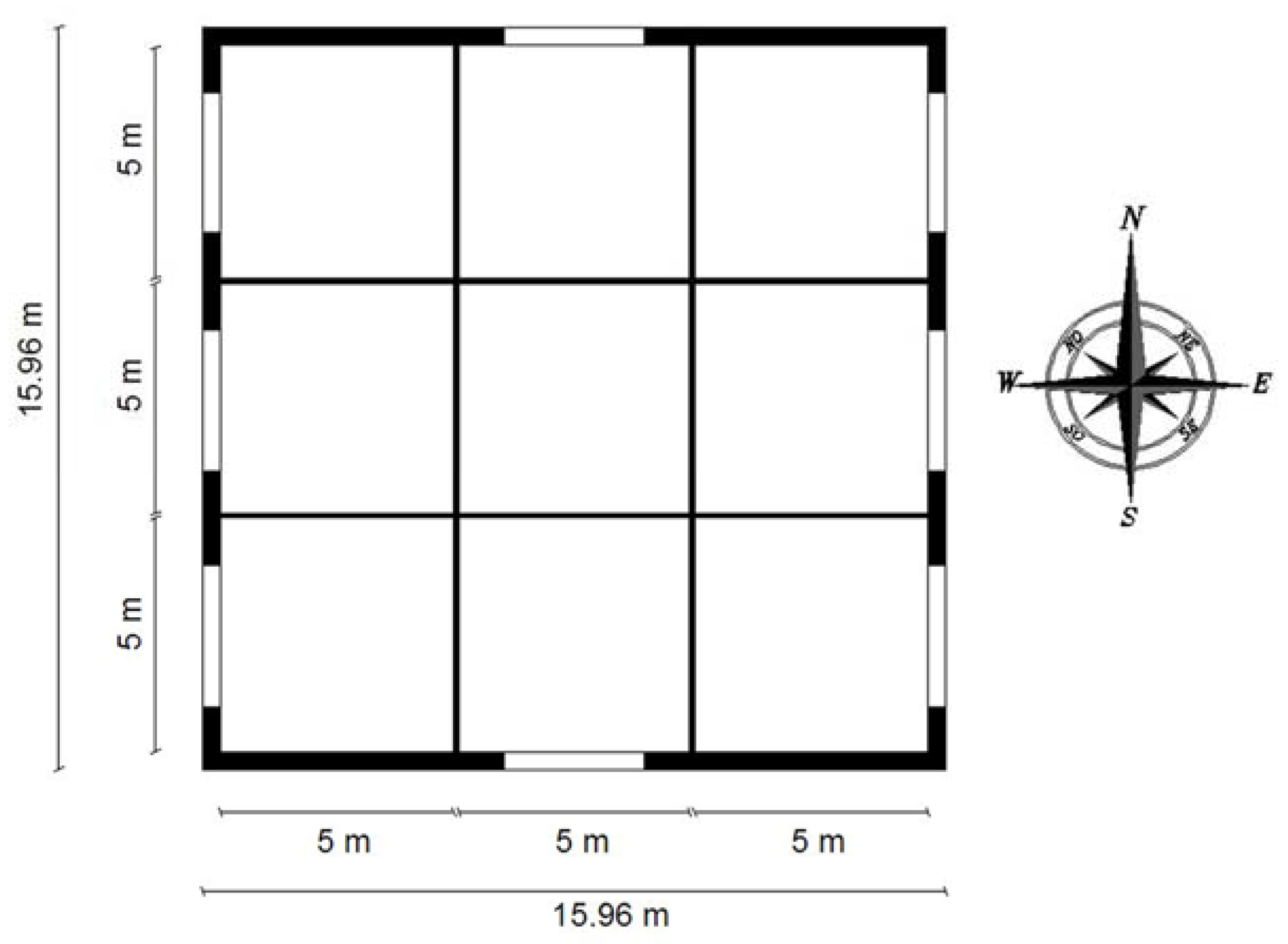
Figure 1. Case study plan.
Energies 10 01808 g001
Figure 2. TRNSYS simulation scheme for building energy analysis.
Energies 10 01808 g002
Figure 3. Evaluation of the windows: Position 1 and Position 2.
Energies 10 01808 g003
Figure 4. TOP graphical trend for the STEP 1 (27 July–2 August; 12 January–18 January).
Energies 10 01808 g004
Figure 5. TOP graphical trend for the STEP 2 (27 July–2 August; 12 January–18 January).
Energies 10 01808 g005
Figure 6. TOP graphical trend for the STEP 3 (27 July–2 August; 12 January–18 January).
Energies 10 01808 g006
Figure 7. TOP graphical trend for the STEP 4 (27 July–2 August; 12 January–18 January).
Energies 10 01808 g007
Figure 8. TOP graphical trend for the STEP 5 and STEP 6 (27 July–2 August; 12 January–18 January).
Energies 10 01808 g008
Figure 9. TOP graphical trend for the STEP 7 and STEP 8 (27 July–2 August; 12 January–18 January).
Energies 10 01808 g009
Figure 10. Winter and Summer peaks of Combo 9 and Combo 10 (from the Table 10 and Table 11).
Energies 10 01808 g010
Figure 11. Predicted mean vote (PMV) and predicted percentage of dissatisfied (PPD) evaluation for Combo 16.
Energies 10 01808 g011
Figure 12. PMV and PPD evaluation for Combo 17.
Energies 10 01808 g012
Figure 13. Comparison of Combo 17 performance with and without ventilation.
Energies 10 01808 g013
Table 1. Development of the methodology.
FIRST STEPExternal wall selectionCombo 1,2,3,4,5
SECOND STEPSlab on ground floor evaluationCombo 4,6
THIRD STEPAnalysis of the roof solar absorbanceCombo 6,7,8
FOURTH STEPEvaluation of the windows positionCombo 9,10
FIFTH STEPSizing of windowsCombo 10,11,12
SIXTH STEPStudy of the impact of window typesCombo 10,13,14
SEVENTH STEPAssessment of shadingCombo 10,15
EIGHTH STEPEstimation of the internal heat loadsCombo 10,15,16,17
Table 2. List of combinations.
ComboWindow Position (Section 2.3.4, Figure 3)Internal Gains (Section 2.3.8, Table 3)Wall (Section 2.3.1, Table 4 and Table 5)Slab on Ground Floor (Section 2.3.2, Table 4, Table 5 and Table 6)Windows (Section 2.3.5, Section 2.3.6, Table 7)Ceiling Absorptance (Section 2.3.3)Shading (Section 2.3.7)
Combo 1NO WINDOWSNOW1IGFNGC0.5
(solar absorbance of 0.5)
NO
Combo 2W2IGFNGC0.5
(solar absorbance of 0.5)
Combo 3W3IGFNGC0.5
(solar absorbance of 0.5)
Combo 4W4IGFNGC0.5
(solar absorbance of 0.5)
Combo 5W5IGFNGC0.5
(solar absorbance of 0.5)
Combo 4NO WINDOWSNOW4IGFNGC0.5
(solar absorbance of 0.5)
NO
Combo 6W4NIGFNGC0.5
(solar absorbance of 0.5)
Combo 6NO WINDOWSNOW4NIGFNGC0.5
(solar absorbance of 0.5)
NO
Combo 7W4NIGFNGC0.3
(solar absorbance of 0.3)
Combo 8W4NIGFNGC0.7
(solar absorbance of 0.7)
Combo 9POSITION 1NOW4NIGFG1
(1/8 of the floor surface)
C0.3
(solar absorbance of 0.3)
NO
Combo 10POSITION 2W4NIGFG1
(1/8 of the floor surface)
C0.3
(solar absorbance of 0.3)
Combo 10POSITION 2NOW4NIGFG1
(1/8 of the floor surface)
C0.3
(solar absorbance of 0.3)
NO
Combo 11POSITION 2W4NIGFG1
(1/7 of the floor surface)
C0.3
(solar absorbance of 0.3)
Combo 12POSITION 2W4NIGFG1
(1/9 of the floor surface)
C0.3
(solar absorbance of 0.3)
Combo 10POSITION 2NOW4NIGFG1
(1/8 of the floor surface)
C0.3
(solar absorbance of 0.3)
NO
Combo 13POSITION 2W4NIGFG2
(1/8 of the floor surface)
C0.3
(solar absorbance of 0.3)
Combo 14POSITION 2W4NIGFG3
(1/8 of the floor surface)
C0.3
(solar absorbance of 0.3)
Combo 10POSITION 2NOW4NIGFG1
(1/8 of the floor surface)
C0.3
(solar absorbance of 0.3)
NO
Combo 15POSITION 2NOW4NIGFG1
(1/8 of the floor surface)
C0.3
(solar absorbance of 0.3)
YES
Combo 16POSITION 2YESW4NIGFG1
(1/8 of the floor surface)
C0.3
(solar absorbance of 0.3)
YES
Combo 17POSITION 2YESW4NIGFG1
(1/8 of the floor surface)
C0.3
(solar absorbance of 0.3)
NO
W = Wall; IGF = Insulated Ground Floor; NIGF = No Insulated Ground Floor; NG = No Windows; G = Glass; C = Ceiling absorptance.
Table 3. Boundary conditions: the internal gains for zone.
Type GainTotal Heat Gain (W)Hour
FromTo
Occupants440:0024:00
Artificial lighting1258:0020:00
Electronic equipment7520:008:00
Table 4. Thermo-physical properties of building materials.
PropertiesMaterialλ (W/m K) Thermal Conductivityc (J/Kg K) Specific Heat Capacityρ (kg/m3) DensityThicknesses (cm)
WallBricks0.13100060020
Tuff stone blocks1.7850230010
Polystyrene0.0341700358
Ground FloorStoneware flooring1.4785017001.5
Concrete (1200 kg/m3)0.4785012008
Concrete (1600 kg/m3)0.7385016005
EPS polystyrene panel0.035850355
Crawl space with igloo0.072850100016
Screed ordinary concrete1.0685017005
Gravel1.285017001
RoofHollow-core concrete0.743850180025
Concrete (400 kg/m3)0.1985040010
XPS polystyrene panel0.04850358
Tuff stone blocks1.7850230010
Tuff stone tiles0.5585016005
Table 5. External walls evaluation.
External WallsUY12Y22Y11fdMs∆tk1k2d
Energies 10 01808 i001W/m2KW/m2KW/m2KW/m2KKg/m2hkJ/m2KkJ/m2Km
W1 Energies 10 01808 i0020.2430.03310.5590.4090.136352.813.35.95145.380.38
W2 Energies 10 01808 i0030.2430.03210.6311.90.132352.813.5726.56146.280.38
W3 Energies 10 01808 i0040.2430.0082.2330.4240.033352.813.515.9130.740.38
W4 Energies 10 01808 i0050.2430.0190.4235.8410.078352.814.5380.435.930.38
W5 Energies 10 01808 i0060.2430.0212.2215.9730.086352.815.1582.2230.560.38
Table 6. Ground floor configurations.
Ground FloorU W/m2KD m
IGF Energies 10 01808 i0070.2330.415
NIGF Energies 10 01808 i0080.3490.365
Table 7. Window properties.
Window MeasuresUg (W/m2K)g% FrameUf (W/m2K)
G16/16/6 Argon1.30.333152.27
G24/16/4 Argon1.40.589152.27
G34/8/4/8/4 Krypton0.70.407152.27
Table 8. Boundary conditions: the ground properties.
Mean surface temperature (°C)10
Amplitude of surface temperature (°C)5
Soil thermal conductivity (kJ/h m K)8.72
Soil density (kg/m3)3200
Soil specific heat (kJ/kg K)0.84
Table 9. Summer operative air temperature (TOP) peaks.
Summer Peaks (°C)
StepComboTOP_STOP_SETOP_WTOP_ETOP_NTOP_SWTOP_CENTRALTOP_NWTOP_NE
First StepCombo 126.6127.0326.7926.5126.2727.2426.1626.9426.62
Combo 226.5626.9526.7326.4726.2227.1526.1226.8426.55
Combo 326.5726.9926.7626.4726.2427.2126.1226.9026.59
Combo 426.4126.7526.5726.3426.0826.9125.9926.6126.38
Combo 526.4526.8026.6126.3826.1226.9526.0426.6626.43
Second StepCombo 426.4126.7526.5726.3426.0826.9125.9926.6126.38
Combo 625.5525.9625.7125.4825.2226.1225.0725.8125.58
Third StepCombo 625.5525.9625.7125.4825.2226.1225.0725.8125.58
Combo 724.9925.4425.1524.9224.6625.6024.4625.2825.05
Combo 826.1026.4726.2626.0425.7826.6225.6626.3326.09
Fourth StepCombo 928.3128.9029.0728.6727.6529.4327.4829.0928.55
Combo 1027.7028.1128.3627.9326.8428.2126.8227.4627.22
Fifth StepCombo 1027.7028.1128.3627.9326.8428.2126.8227.4627.22
Combo 1128.0528.4528.8028.3327.1228.5627.1327.7627.49
Combo 1227.4227.8328.0227.6126.6227.9426.5827.2327.00
Sixth StepCombo 1027.7028.1128.3627.9326.8428.2126.8227.4627.22
Combo 1329.8130.1630.8730.2928.4630.2228.6129.1328.83
Combo 1428.2128.6129.0628.6327.2628.6927.2727.8627.64
Seventh StepCombo 1027.7028.1128.3627.9326.8428.2126.8227.4627.22
Combo 1525.8326.2126.0925.7925.5626.3625.2426.1325.90
Eighth StepCombo 1027.7028.1128.3627.9326.8428.2226.8227.4627.22
Combo 1525.8326.2126.0925.7925.5626.3625.2426.1325.90
Combo 1628.9129.0529.2128.2128.6829.2228.6629.0428.81
Combo 1730.7830.9431.4730.9829.9731.0530.2430.3730.12
Table 10. Winter TOP peaks.
Winter Peaks (°C)
StepComboTOP_STOP_SETOP_WTOP_ETOP_NTOP_SWTOP_CENTRALTOP_NWTOP_NE
First StepCombo 17.407.237.327.327.277.237.467.137.13
Combo 27.517.357.437.427.377.357.557.247.24
Combo 37.557.387.467.467.417.397.587.277.27
Combo 47.787.657.697.697.637.657.767.537.52
Combo 57.687.547.597.597.547.557.687.437.42
Second StepCombo 47.787.657.697.697.637.657.767.537.52
Combo 67.557.447.467.467.407.447.537.327.31
Third StepCombo 67.557.447.467.467.407.447.537.327.31
Combo 77.437.3357.347.347.297.337.397.207.20
Combo 87.677.557.587.587.527.557.657.437.426
Fourth StepCombo 97.987.797.817.797.707.817.967.627.59
Combo 108.228.067.957.947.768.078.107.667.65
Fifth StepCombo 108.228.067.957.947.768.078.107.667.65
Combo 118.318.158.028.017.828.168.197.717.70
Combo 128.147.997.897.887.728.008.037.627.61
Sixth StepCombo 108.228.067.957.947.768.078.107.667.65
Combo 139.018.828.618.598.328.838.798.198.17
Combo 148.528.358.218.197.998.368.357.887.87
Seventh StepCombo 108.228.067.957.947.768.078.107.667.65
Combo 157.387.277.297.297.237.277.427.157.14
Eighth StepCombo 108.228.067.957.947.768.078.107.667.65
Combo 157.387.277.297.297.237.277.427.1517.14
Combo 1610.4110.0710.3510.3510.3010.0710.7810.0010.00
Combo 1711.2510.8611.0010.9910.8310.8711.4610.5110.50
Table 11. TOP analysis for the Combo 17.
Y12Y22Y11fd∆tk1k2Summer TOP
W/m2KW/m2KW/m2KhkJ/m2KkJ/m2KSSEWENSWCENTRALNWNE
W10.03310.5590.4090.13613.35.95145.3826.6127.0326.7926.5126.2727.2426.1626.9426.62
W20.03210.6311.90.13213.5726.56146.2826.5626.9526.7326.4726.2227.1526.1226.8426.55
W30.0082.2330.4240.03313.515.9130.7426.5726.9926.7626.4726.2427.2126.1226.926.59
W40.0190.4235.8410.07814.5380.435.9326.4126.7526.5726.3426.0826.9125.9926.6126.38
W50.0212.2215.9730.08615.1582.2230.5626.4526.826.6126.3826.1226.9526.0426.6626.43
Table 12. TOP analysis for the Combo 17.
Y12Y22Y11fd∆tk1k2Winter TOP
W/m2KW/m2KW/m2KhkJ/m2KkJ/m2KSSEWENSWCENTRALNWNE
W10.03310.5590.4090.13613.35.95145.387.47.237.327.327.277.237.467.137.13
W20.03210.6311.90.13213.5726.56146.287.517.357.437.427.377.357.557.247.24
W30.0082.2330.4240.03313.515.9130.747.557.387.467.467.417.397.587.277.27
W40.0190.4235.8410.07814.5380.435.937.787.657.697.697.637.657.767.537.52
W50.0212.2215.9730.08615.1582.2230.567.687.547.597.597.547.557.687.437.42
Table 13. TOP analysis for the Combo 17.
Combo 17—Operative Air Temperature (°C)
Annual TemperatureSSEWENSWCentralNWNE
Minimum Value11.2510.8611.0010.9910.8310.8711.4610.5210.51
Middle Value21.0920.9420.7420.7220.1720.9620.7320.1120.09
Maximum Value30.7830.9431.4730.9829.9731.0530.2430.3730.12
Average Monthly TemperatureSSEWENSWCentralNWNE
January13.6213.3713.0012.9812.6213.3913.1912.4612.45
February15.2515.1014.7414.7914.2515.0814.8014.1414.18
March15.5815.4315.0715.1014.5415.4215.0914.4514.47
April18.6118.4418.4118.3117.7918.5118.3317.7517.68
May21.1921.1621.2921.2520.6921.1921.0420.7420.71
June25.2825.2725.5825.5325.0525.3125.3025.1025.07
July28.4528.4728.7328.6628.1228.5228.3928.2228.18
August29.5029.4329.4629.3928.7529.4829.2428.8028.75
September27.6427.4527.1127.0926.3527.4727.1026.2926.27
October24.4924.2323.6923.6422.9724.2623.8022.8622.83
November19.0318.7318.2618.3017.7918.7118.5417.5717.60
December15.3015.0014.5514.5314.1015.0214.7913.9013.89