
An Innovative Approach for Gob-Side Entry Retaining in Thick Coal Seam Longwall Mining

1
State Key Laboratory for Geomechanics & Deep Underground Engineering, China University of Mining & Technology, Beijing 100083, China
2
School of Mechanics and Civil Engineering, China University of Mining & Technology, Beijing 100083, China
*
Author to whom correspondence should be addressed.
†
These authors contributed equally to this work.
Energies 2017, 10(11), 1785; https://doi.org/10.3390/en10111785
Submission received: 3 October 2017
/
Revised: 31 October 2017
/
Accepted: 2 November 2017
/
Published: 6 November 2017
(This article belongs to the Special Issue Mathematical and Computational Modeling in Geothermal Engineering)
Abstract
:Gob-side entry retaining (GER) is a popular non-pillar mining technique regarding how to reserve a gateroad for the use of next panel mining. When used in thick coal seams, the conventional entry retaining method requires a huge amount of filling materials and may cause entry (gateroad) accidents. Thus, an innovative non-pillar longwall mining approach is introduced. First, structural and mechanical models were built to explore the mechanism of the new approach. The modeling results indicate that effective bulking of the gob roof and reasonable support of the entry roof were key governing factors in improving entry stabilities and reducing roof deformations. Accordingly, a directional roof fracturing technique was proposed to contribute to gob roof caving, and a constant resistance and large deformation anchor (CRLDA) cable was used to stabilize the entry roof. Subsequently, the evolutionary laws of the roof structure and stresses were explored using numerical simulation. It was found that the structure of the surrounding rocks around the retained entry changed significantly after roof fracturing. The stress-bearing center was transferred to the gob area, and the entry roof was in a low stress environment after adopting the approach. Finally, the approach was tested on a thick coal seam longwall mining panel. Field monitoring indicates that the retained entry was in a stable state and the index of the retained entry met the requirement of the next mining panel. This work provides an effective and economical approach to non-pillar longwall mining in thick coal seams.
1. Introduction
Coal is among the most important foundational energies, accounting for approximately 30% of total energy consumption around the world [1,2]. Presently, longwall mining and room-and-pillar mining have been the two most popular methods for underground coal mining. Because longwall mining has higher production rates, less manpower requirements, and safer working conditions as compared with that of the others, over 90% of underground coal mines adopted the longwall mining in China [3]. The longwall mining approach involves one mining panel with two entries in both sides that are mainly used for transportation and ventilation, termed the ‘headentry’ and ‘tailentry’. According to the size of a coal pillar between two mining panels, the longwall mining technique can be classified into three categories: large-pillar mining, narrow small-pillar mining, and zero-pillar mining [4], as illustrated in Figure 1.
As seen from Figure 1, in the large- and small-pillar mining schemes, barrier pillars are left untouched, and the roof of the mined-out area collapses with the progressive advance of the working face. Generally, the pillar width for large-pillar mining ranges from 20 m to 50 m, which is favorable for avoiding strong disturbances from adjacent mining faces. When the current mining panel is working, the tail entry or head entry for the next mining panel can be tunneled at the same time. This type of mining pattern is especially suitable for the condition where many panels must be mined simultaneously. Generally, stabilities of the entry in the large-pillar mining pattern can be well guaranteed. However, oversize pillars usually cause large amounts of waste, accounting for approximately 10% to 30% of the total coal production. The small-pillar mining pattern is also known as gob-side entry driving. The recovery ratio of this type of mining pattern is much larger than that of the large-pillar mining. However, the size of the pillar is difficult to be accurately determined. If the width of the pillar is irrational, mining-induced fractures in the pillar may lead to air leakage, spontaneous combustion or other mining accidents [5,6,7]. Accordingly, it is imperative to find an environmentally-friendly, resource-efficient and more safe mining approach.
In development since the early 1950s, Gob-side entry retaining (GER) is one of the most commonly used techniques in the long-wall mining belonging to the zero-pillar mining (Figure 1c). In this technique, the former entry is artificially retained as the tailgate for the next mining panel by using pigsties, concrete blocks, paste-like backfill material, high-water packing material, and other fill materials. The application of this technique can not only increase coal recovery rates and reduce roadway drivage ratios, but also improve the condition of the mining panel replacements [8,9]. Since the retained entry in the zero-pillar mining will experience more dynamic mining disturbances, the entry control techniques appear to be very important. Much research has been conducted on GER applied on thin and medium coal seams regarding the properties and stability of filling bodies [10,11,12], the transfer bearing mechanisms of roofs [13,14,15], and deformation control of retained entries [16,17,18]. Up to now, however, studies of Gob-side entry retaining applied in thick coal seams have rarely seen in the published literatures [19]. When conventional GER is applied in thick coal seams, the retained entry will experience higher stress conditions and thus more instability problems [20,21]. In addition, excessive consumption of filling materials also sets limits on the use of GER in thick coal seams.
Therefore, we present an innovative non-pillar longwall mining approach by fracturing roofs to maintain entry (FRME). In this approach, the geometry of the entry and gob roofs is actively controlled by roof fracturing along with active support, thus reducing stress in the retained entry. Additionally, bulking characteristics of the caving gangues at the gob area are efficiently used, and no extra man-made filling material is therefore needed, which makes the FRME approach more flexible and cost effective. In this work, the mechanism of the FRME approach was first studied by mechanical and numerical modeling. Based on the migration laws of roof structures, a matching design was developed and tested in a field application. The applicative effects indicate that the proposed FRME approach has broad application prospects for sustainable mining of thick coal seams.
2. An Innovative Approach for Gob-Side Entry Retaining
2.1. Principle of the Fracturing Roofs to Maintain Entry (FRME) Approach
In longwall mining, extraction activities cause disturbances of the original equilibrium state. During stress redistribution processes, the roof rock strata fracture and cave periodically at some distance behind the hydraulic support into the gob area. When the roof strata collapse, the intact rock breaks into pieces, causing the volume of caving gangue to be larger than the original rock.
In the FRME approach, when the current mining face is mined out, the bulking gangue body is utilized to maintain I headentry, as shown in Figure 2. The retained entry (I headentry) then becomes the tailentry of the next mining face, with the artificial filling materials in the conventional entry retaining method being creatively replaced by the bulking gangue body. Compared with large-pillar and small-pillar mining methods, the advantages of this technology are that more coal resources are exploited and less gateroad is excavated. Compared with GER belonging to zero-pillar mining, this new technique does not need extra artificial filling materials any more, which makes it more economic and applicative applied in thick coal seams.
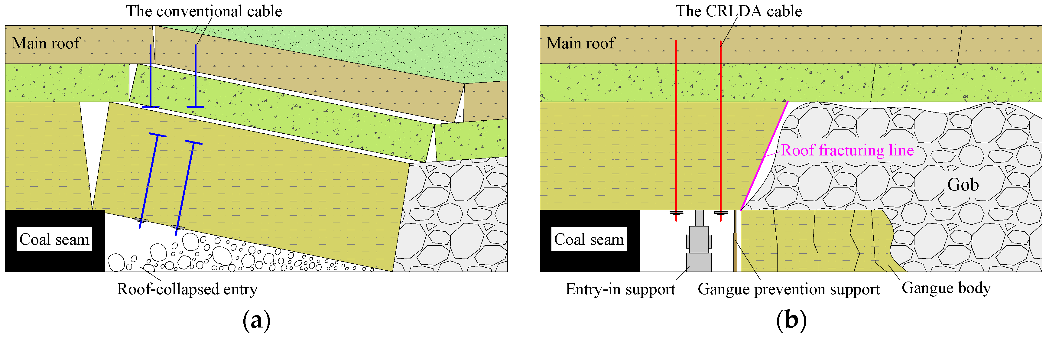
In this approach, roof fracturing is an essential process. It can alter the roof connection status and prevent stress propagation from the gob roof to entry roof. Before roof fracturing, the entry roof is one part of the long hanging roof structure, and their movements are intimately associated, as shown in Figure 3a. After roof fracturing, the gob roof strata fracture and cave under the action of roof weighting. The caved gangues expand to support and control the deformation of the upper main roof. Nevertheless, the entry roof remains stable under the entry-in support, as illustrated in Figure 3b. Therefore, the essence of the FRME approach is the active control of the entry roof and effective utilization of the bulking characteristics of the gob roof rock.
2.2. Mechanical Model
Roof deformation control is one of the difficulties in non-pillar mining. To explore the governing factors of roof deformations in the FRME approach, we built a mechanical model that emphasized the fractured entry roof. According to the structural characteristics of the surrounding rocks, the fractured entry roof can be simplified as an elastic rock beam [22]. One side of the rock beam is supported by the bulking gangue body, and the other side is clamped, as shown in Figure 4. In this model, the gangue support is equivalent to a concentrated spring force F. Based on elasticity theory, the roof deformation equation can be written as:
where is the bending moment along the coal seam dip, is the elasticity modulus of the roof rock, and is the moment of inertia of the beam section.
The bending moment can also be written as:
where is the combined load of the top cover (q0), roof beam gravity (g) and active cable support (q1), written as . is the length of the roof beam, and is the roof fracturing angle.
The fixed end of the rock beam is clamped by the intact coal body of next mining panel and the roof rock. According to the theory of elastic mechanics, the vertical displacement and velocity of the fixed point (original point in the model) are both zero. The boundary condition of the model can be expressed as:
According to Equations (1)–(3), the bending amount can be obtained as:
When x equals l, the maximum bend amount of the entry roof will be:
From Equation (5), we can understand that, apart from the objective factors, an effective way to reduce roof deformation is to increase the slant support F, which can be achieved by taking advantage of the load-bearing role of the gangue body. In addition, reasonable active support (q1) can also help decrease the amount of roof sagging. Accordingly, two key techniques to decrease entry roof deformation for the FRME approach are proposed in this study.
2.3. Key Techniques of the FRME Approach
2.3.1. Directional Roof Fracturing Technique
As seen from the principle and mechanical analyses of the FRME approach, sufficient gangues beside the entry appear quite essential. On the one hand, the gangues can control the main roof, reducing rotational deformation as a support. Additionally, they can turn into the natural filling body, maintaining the entry as a rib. When solid rock is broken, the volume of broken rock increases compared with the original rock. The main reason is that the broken rock pieces are irregular in shape and typically do not fit together perfectly, resulting in more void room [23]. Considering this, we proposed a new roof fracturing technique that can not only enhance caving and bulking of the gob roof but also maintain the integrity of the entry roof.
As illustrated in Figure 5, the technique’s main feature is that it can control the propagation direction of cracks using an energy-accumulated device. At the surface of this specially designed device, there are two rows of energy-accumulated grooves at 180° angles from each other. Before roof fracturing, explosive cartridges and the energy-accumulated device are installed in the blasting hole. During blasting, the detonation generates high-speed, high-temperature and high-pressure gases that intensively act on the grooves and promote cracks that propagate in the controlled direction. Ultimately, with the propagation of cracks, the adjacent holes coalesce and form an integrated fracturing line or structural plane.
2.3.2. Constant Resistance and Large Deformation Anchor (CRLDA) Cable Support Technique
It can be seen from Equation (5) that the artificial entry-in support decreases with increases in the gangue body support. However, owing to the mining height effect, extra room remains between the upper main roof and the gangues at the initial stage of gob roof caving. Accordingly, the entry-in support elements should not only have good support performance but also allow some amount of controlled deformation. In this case, the load-carrying capacity of the surrounding rocks can be fully utilized, which is also favorable to the stability and safety of the entry in follow-up maintenance.
We therefore invented a new cable, the CRLDA cable. The CRLDA cable is characterized by having extraordinarily large elongation with high constant resistance and, as such, is especially robust for damping dynamic loads [24,25]. The key element of the CRLDA cable is a man-made device called the constant resistance device, which is installed above the face pallet. This device makes it possible for the CRLDA cable to safely yield for a distance, so that the self-bearing of bulking gangues can be fully utilized.
Figure 6a shows the working principle of the CRLDA cable in stabilizing the entry roof, and Figure 6b shows the corresponding synergic bearing of the CRLDA cable and gangues. Note that the gangues experience exponential increase under continuous compression [26]. Before the surrounding rock is deformed, the anchored end is bonded by means of an anchoring agent in the interior stable rock. When roof deformation is induced by dynamic pressure from gob roof caving, the tensile load of the stranded steel rope increases rapidly. If the rock deformation is within the elastic limit of the CRLDA cable (phase I, from A to B), little or no relative slippage will occur between the constant resistance device and stranded steel rope. In this case, the tensile force of the CRLDA cable increases linearly with the increase in rock deformation [27], whereas no bearing loading occurs on the gangues.
When the roof loading reaches a constant resistance , the tensile forces in the anchor cables remain nearly constant (from B to C). The constant resistance device slips along the rope until the upper main roof comes into contact with the gangues (phase II). Subsequently, the gangues begin to take load from the upper strata (phase III). When the CRLDA cable and gangues take the full load of the overburden weight, the entry becomes stable. The CRLDA cable can always remain effective throughout the entire process.
3. Laws of the Roof Structure and Stresses
3.1. Structure Characteristics of Surrounding Rocks
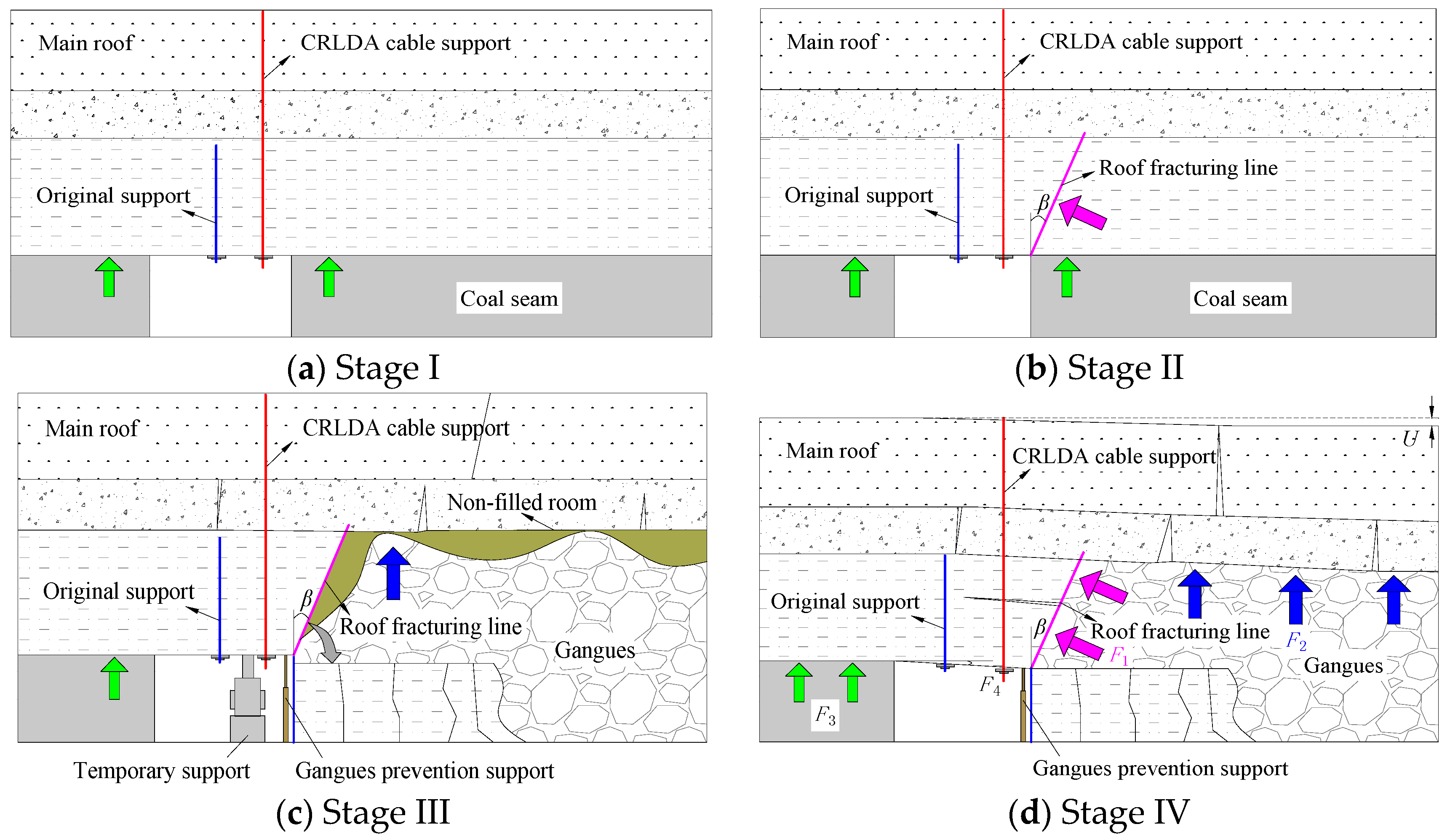
Based on the characteristics and steady states of the surrounding rocks, the FRME processes can be divided into four stages: the original stage (Stage I), roof fracturing stage (Stage II), dynamic stage after mining (Stage III), and stable stage (Stage IV), as illustrated in Figure 7.
Stage I: The concentrated stress in the surrounding rock is mainly caused by entry excavation. In this stage, proper construction of the CRLDA cable is imperative. Generally, the length of the CRLDA cable should be longer than the fracturing height, and the anchoring point must be fixed in the stable roof rock. In this case, the anchoring end can be well protected. In this stage, the roof strata are primarily supported by the intact coal on both sides. The entry roof structure can be regarded as a beam structure with a fixed-fixed condition, so the entry is in the most stable state of all the stages.
Stage II: During this stage, roof fracturing holes are drilled first in a line at the intersection of the entry roof and mining face. Subsequently, the holes are directionally blasted in front of the retreating face using the energy-accumulated device. This operation changes the roof into a beam structure with a simply supported condition, but the roof is still shared by intact coal bodies. The retained entry in this stage is therefore considered to be in a relatively stable state.
Stage III: As coal is progressively extracted, the retreating face reaches the roof fracturing position. The gob roof rock falls along the fracturing line and breaks into irregular shapes of various sizes. Those gangues then become the entry maintenance body. Although the rock volume in its broken state is considerably larger than that of the original state, some non-filled room remains between the gangues and main roof. The gangues in the gob are in caving or compacting states, which can induce dynamic loading on the entry roof. The roof strata can be viewed as a beam structure with a cantilever condition in an unstable state, and therefore, the temporary entry-in support and gangue prevention support should be carried out during this stage.
Stage IV: Under the action of gravity and periodic weighting, the gangues gradually become sufficiently compacted to bear the weight of the overlying strata. In this stage, the temporary support can be removed. Instead, the CRLDA cable plays a leading role as an active support.
From the entire process, we can see that the overlying stratum is mainly supported by three parts: the gangue body (F1 and F2), the intact coal body of the non-fracturing side (F3), and the artificial support (F4), as shown in Figure 7d. The artificial and natural rock supports work together to control roof deformation. Taking full advantage of the self-equilibration of the surrounding rocks can reduce the artificial support and improve the stability of the retained entry.
3.2. Stress Evolution during the FRME Processes
3.2.1. Geological Details
The selected S1201 panel of the Ningtiaota coal mine is located near the city of Yulin, Shanxi Province, China. The panel is approximately 295 m wide along dip and 3010 m long along strike, with a dip angle of less than 2°. Full-seam, comprehensive mechanized, and retreating mining methods are used at S1201 mining panel. The mean thickness of the coal seam is 4.0 m, with an overburden ranging from 80 m to 160 m. The roof strata of this panel are mainly composed of hard sandstones. The immediate roof is siltstone with an average thickness of 4.40 m, and the main roof are quartz sandstone and medium-grain sandstone. Below the coal seam, the floor consists of siltstone and fine-grain sandstone, with average thicknesses of 8.1 m and 12.3 m, respectively. The lithology of the rock layers near coal seam 2-2 is shown in Figure 8.
3.2.2. Global Model
Considering the processes of the FRME approach, a 3D numerical model encompassing the roof fracturing of the S1201 headentry was developed, as illustrated in Figure 9. The dimensions selected for the model were 400 m long, 200 m wide, and 50 m high, based on the geological column. The average mining depth in the simulation is chosen to be 120 m. The minimum horizontal stress-to-vertical stress ratio is kept as 0.8, according to the in-situ stresses of No. 2-2 coal seam, and the model’s bottom and horizontal sides are roller constrained.
In the model, the Mohr-Coulomb criterion is used to simulate the behaviour of the rock strata. The Mohr-Coulomb model is a mathematical model describing the response of brittle materials to shear stress as well as normal stress. The Mohr-Coulomb failure criterion represents the linear envelope that is obtained from a plot of the shear strength of the rock versus the applied normal stress, expressed as:
where is the shear strength, is the normal stress, is the cohesion and is the angle of internal friction.
To obtain the mechanics parameters of the constitutive model, some specimens taken from Ningtiaota coal mine were tested in the laboratory. The uniaxial compressive strength, Young’s modulus, and Poisson’s ratio were obtained from uniaxial compression tests. Triaxial compression tests were carried out to obtain fiction angle and cohesion. The detailed rock mass properties for numerical simulation are listed in Table 1.
3.2.3. Simulation Plans and Results
In the present study, both the fracturing and non-fracturing conditions were simulated to examine the effects of the FRME approach on the surrounding rock stresses. The simulation process is as follows: (i) apply an in situ stress state, (ii) excavate the entry and apply support until equilibrium is reached, (iii) fracture the roof on one side near the gob area (note that the fracturing height is 9 m and the fracturing degree is 10° based on the actual application), (iv) extract the panel in retreat along the mining direction, and (v) extract the panel again after step ii for comparison with the roof fracturing condition.
(1) Stress distributions on the entry sides
During each staged excavation, monitoring points were established on the integrated coal (non-fracturing side) and worked out (fracturing side) sections to monitor the vertical stress, as indicated in Figure 8. Here, it is worth noting that the bulking characteristics of the gangues around the fracturing line were accounted for. Figure 10 presents the vertical stress distributions of the non-fracturing and fracturing sides at different stages.
The numerical simulation results indicate that roof fracturing exerts an obvious influence on the response of surrounding rock stresses.
Before mining, roadway excavation can cause stress to concentrate. The vertical stress first increases and then decreases to the in situ stresses on both sides. These results agree with the investigations discussed in the literature [15]. Before the S1201 panel mining, roof fracturing had little influence on the vertical stress of the non-fracturing side, whereas it probably would slightly reduce the overall strength of the fracturing side.
However, roof fracturing had a dramatic influence on the stress distribution after mining. Before roof fracturing, the stress concentration area was located on the non-fracturing side, peaking at 9.0 MPa, whereas the vertical stress at the gob area was small, climbing to 2.49 MPa 43 m from the entry side. In contrast, there was a significant drop in the peak stress at the non-fracturing side after roof fracturing, decreasing approximately 5.5 MPa to 3.5 MPa. Simultaneously, the vertical stress in the gob area showed a considerable increase of 5 MPa to approximately 5.4 MPa.
(2) Stress distributions on the entry roof
The vertical stress above the entry was also monitored in the simulation. Figure 11 presents the variations in stress at different monitoring points above the entry roof (5 m, 10 m, 20 m, and 30 m) during the simulation process. The red lines illustrate the changing process of the vertical stress under the condition that the entry roof was not fractured, and the olive lines show the changing process of the vertical stress when the entry roof was fractured before mining.
The simulated results indicate that roof fracturing had a significant impact on the stress distribution and variations on the entry roof. The vertical stress was much smaller than that in the non-fracturing condition, especially when the measured point was within the fracturing-affected area (see Figure 11a,b). In addition, the fluctuation range was also smaller under fracturing conditions. This proves that the fracturing operation can prevent stress propagation from the gob roof to entry roof. However, the influence progressively decreased for monitoring positions far from the fracturing area (see Figure 11c,d).
4. Fracturing Roofs to Maintain Entry (FRME) Design
4.1. Roof Fracturing Design
(1) Roof fracturing height
Theoretically, the roof fracturing height should be sufficiently high to cause the mining room to fill with caving gangues [28]. In addition to the bulking characteristics of the gob roof, floor heave and roof sagging should also be considered. The fracturing height can be calculated by:
where is the mining height, is the amount of bottom bulging, is the amount of floor sagging, and is the bulking factor of the top covers.
Among these influencing factors, the bulking factor has a major influence on caving effects. The bulking factor is defined as the ratio of the volume of the broken rock strata to the original volume of the same strata before they are broken or cave. It varies with rock type, shape, and size of the caved fragments [29]. The bulking factor k can be estimated by [30]:
where is the mining height and is the height of the caved zones.
For the S1201 panel, the mining height is 4.17 m, while the height of the caved zones was estimated to be 10.5 m according to the geologic report. Based on the above equation, the bulking factor was calculated to be 1.39. The average amounts of bottom bulging and floor sagging were measured to be 310 mm and 360 mm, respectively. Thus, considering the theoretical calculation and field condition, a 9.0 m fracturing height was chosen after careful analysis.
(2) Roof fracturing direction
The relative sliding motion between the gob roof and entry roof is a key consideration during fracturing direction design. A suitable roof fracturing degree is favorable for gob roof caving and can reduce the influence of caving on the entry roof.
As illustrated in Figure 12a, when the fracturing direction points to the entry roof, the caving of the gob roof can generate a downward pressure , which is likely to cause a large deformation of the entry roof during the caving process.
When the fracturing line is perpendicular to the roof, the fracturing length is at a minimum to the fracturing height. However, there is still a frictional resistance between the gob roof and entry roof, as shown in Figure 12b. In addition, the slant support in Equation (2) to the entry roof from the gangue body may significantly decrease, which may increase the entry-in support.
Conversely, when the fracturing direction points to the gob roof, the frictional resistance would dramatically decrease, which is beneficial to both gob roof caving and entry stability. Nevertheless, with an increase in the fracturing degree, the fracturing length and construction cost increase as well, i.e., L4 is longer than L3. Additionally, based on the actual situation, the coal-carrying trap has been installed before the gob-side entry retained in the S1201 headentry. If the fracturing degree were too large (more than 14°), roof fracturing construction would be difficult to carry out, as illustrated in Figure 12d.
Therefore, considering all factors, the ultimate roof fracturing degree was designed to be 10°, as shown in Figure 12c.
4.2. Entry Support Design
4.2.1. Entry-in Support
Apart from the primary support, the entry roof needs reinforcing during the FRME processes. The reinforced entry-in support includes temporary and permanent supports. The temporary support mainly works to help stabilize the entry (Stage III) and can be removed and reused once the entry has stabilized. The permanent support primarily works after the temporary support has been removed (Stage IV).
From the above description, a small amount of yielding deformation contributes to decreasing the entry-in support and improving the bearing capacity of the surrounding rocks. Ordinary support often loses efficacy when yielding. Thus, the pier-beam unit support and CRLDA cable, both with yielding characters, were specially designed and applied in the test.
Yielding resistance is among the most important parameters of the temporary support design. Considering primary loads of hydraulic support near the entry and effects of roof fracturing, the yield resistance of the pier-beam unit support was chosen to be 4000 kN. If the entry roof loading exceeded the set value, the pier-beam unit support would yield to make the gangues share the overloading. The detailed arrangement of the temporary support is shown in Figure 13.
In consideration of the designed roof fracturing height, roof fracturing direction, primary support intensity, and slant support from the gangues, the CRLDA cables, which were 21.8 mm in diameter and 10,500 mm in length, were used as reinforcing supports. The CRLDA cable rows were designed to be 1000 mm along the length of the entry. The adjacent cables were connected by a W-shape steel strip. The constant resistance and constant resistance distance were 350 kN and 500 mm, respectively. The detailed support pattern is illustrated in Figure 13.
4.2.2. Entry-Side Support
The entry-side support (gangue prevention support) is highly related to the deformation of the gangue rib. The gangue prevention design should be consistent with the general design idea. Accordingly, a U-steel structure with a displacement releasing property was used in the test. The device was composed of two U-steel units fastened by two fasteners, which made it strong enough to resist lateral deformation. When the roof sagged, the two units slid relatively to adapt to the vertical deformation, as shown in Figure 14.
The interval of any adjacent gangue prevention device was 600 mm, and there was a metal net with a mesh size of 80 mm × 80 mm between the device and gangues. The metal net was able to prevent small gangues from extruding out into the entry.
5. Field Test and Monitoring
5.1. Construction of Key Techniques
(1) Roof fracturing construction
In the field application, the presplitting blasting technique was used to fracture the entry roof. The detailed construction process was as follows (see Figure 15).
- (i)
- Drill blasting holes. The hole diameter and depth were 46 mm and 9139 mm, respectively. To reduce dynamic effects from gob roof caving, the drilling direction of each hole should be consistent.
- (ii)
- Conduct blasting tests. Because there are always errors in theoretical calculations, site tests were essential to obtain the optimal charging parameters. First, we experimented with single hole blasting to determine the base charge and rational stemming length. Subsequently, double nonadjacent hole blasting was conducted to determine a rational charge amount and hole distance. The blasting effects were evaluated by the degree of crack propagation for the middle hole as obtained by borehole imaging. If the crack growth rate did not meet the specification (90%), an adjacent hole blasting experiment was performed to obtain the optimal blasting parameters. The ultimate blasting in the S1201 headentry adopted an air-space charge with borehole spacing of 600 mm and a charge structure with a “3 + 3 + 3 + 3 + 2” pattern, as shown in Figure 16.
- (iii)
- Perform roof fracturing. On the basis of the predefined blasting parameters, energy-accumulated devices filled with emulsified blasting powder were installed in the holes. It is noteworthy that the energy-accumulated grooves must point in the same direction, as shown in Figure 15d. After blasting, the cracks formed a whole roof fracturing line at the roof surface (see Figure 15e). The unfolded inner surface images of the blasting holes illustrate that the energy-gathered effect of the directional roof fracturing technique was effective, as shown in Figure 15f.
(2) The CRLDA cable construction
The construction process of the CRLDA cable can be expressed as follows (see Figure 17).
- (i)
- Drilling and chambering. Before drilling, the cable locations should be marked based on the design. The drilling hole diameters were 28 mm, and the drilling direction was vertical to the entry roof. After drilling, a chambering drill bit with diameter of 75 mm was used to enlarge the holes. The chambering depth was 500 mm.
- (ii)
- Install stranded steel rope and anchoring resin. The anchoring resins were first transported to the anchored end through a PVC air duct hose. The resins were used to fix the top of the steel rope on the stable roof rock. The stranded steel rope was then pushed to the hole end and used to stir the anchoring resins for approximately 20 to 30 s, as shown in Figure 17b. After the resin has been solidified, the accessories of the CRLDA cable were finally installed.
- (iii)
- Install the accessories (see Figure 17c). In this step, a W-type steel band, a constant resistance device, a cable plate, and a cable lock were fixed in turn on the stranded steel rope.
- (iv)
5.2. Field Monitoring
To better understand the laws of the surrounding rock motion and manifestation of the mine pressure, observational stations were arranged at the active working panel and retained entry. The roof pressure of both the working panel and retained entry were recorded. The roof pressure of the active working panel was measured using a KJ216 pressure monitoring apparatus, and the entry roof pressure (including on the fracturing and non-fracturing sides) was measured using a KJ27 pressure monitoring apparatus. Both apparatuses could continuously and automatically record the roof pressure during the mining process. The lateral pressure of the gangue rib was measured using a DP-6 pressure cell. In addition, the vertical and transverse deformations of the S1201 headentry were monitored using a YHU200 apparatus at corresponding positions. The detailed monitoring layout is shown in Figure 18.
In the monitoring processes, the real-time pressure or displacement was first transformed into electric resistance signals underground. The signals were then transmitted through a fiber and an adapter to the ground for processing. The evolutionary character of the pressure and displacement could then be recorded with respect to the advancing mining face.
5.2.1. Pressure Characteristics
(1) Roof pressure in the active working panel
The FRME approach has been tested in the Ningtiaota coal mine since 24 March 2016, before which the roof was not fractured. To study the influence of roof fracturing on pressure variations in the active working panel, monitoring apparatuses were installed at typical positions of the mining panel (A, B, and C stations). A station was 5 m from the entry, representing those positions that were near to the fracturing line. B station was 160 m from the entry, representing middle positions of the working panel. C station was 281 m from the entry, representing those positions that were far from the fracturing line. The monitoring results from 14 March to 3 April 2016 are presented in Figure 19.
As seen from the monitoring results, the periodic weighting loads decreased after adopting the FRME approach. This was particularly obvious when the monitoring stations were close to the fracturing line. The maximum weighting load decreased to 19.5 MPa and the average weighting load dropped by appropriately 60% at the C station. However, the pressure variations at the A and B stations were slight, indicating that the weighting loads were only affected by fracturing within a limited area. The farther the monitoring stations were from the fracturing line, the less they were likely to be affected. In addition, the weighting loads of the middle positions (B station) were larger than those on the sides of the working panel (A and C stations).
Additionally, the periodic weighting intervals increased within the fracturing-affected area after adopting the new approach. When the monitoring station was 5 m from the entry, the mean periodic weighting interval increased by about 32% to 14.4 m. When the monitoring station was at the middle of the panel, the mean periodic weighting interval increased by appropriately 16.8%. This was probably caused by bulking effects of the gangues. Accelerated by roof fracturing, the bulking gangues provided an extra support to the main roof, thus resulting in decreased periodic weighting loads and increased periodic weighting intervals.
(2) Roof and rib pressure in the retained entry
The roof caving or gangue compaction in the gob area plays an important role in the variation in the entry pressure. Figure 20 shows the measured pressures of the entry roof and gangue rib in the S1201 headentry as the S1201 panel retreated.
The variation tendencies of the roof pressures on the fracturing and non-fracturing sides were quite similar, although the pressure on the fracturing side was larger. The decrease in the roof pressure when the monitoring site was close to the active panel was an interesting phenomenon. This was mainly caused by the pre-fracturing of the roof. Initially, the entry roof and gob roof comprised a whole structure, and the support bore the entire weight of the structure. Partially due to roof fracturing, the immediate roof and lower main roof caved in the gob area after mining. Thus, the overburden weight decreased, resulting in the decrease of the roof pressure. When the active S1201 panel passed the monitoring site at distances of 23 m and 52 m (A and B positions), the roof pressure jumped when the upper main roof fractured. Subsequently, the pressure increased gently to a plateau, which corresponded to the compaction process of the gob gangues. When the monitoring site was 115 m or more from the active S1201 panel (C position), the roof pressure reached the yield load of the temporary support, and the support worked at a constant resistance status.
Compared with the roof pressure, the lateral pressure of the gangue rib was much smaller. Much of the lateral pressure growth was concentrated within 30 m from the active panel, especially in the fracture position of the upper main roof (A and B positions). When the active S1201 panel passed 60 m the monitoring site, the lateral pressure was almost stabilized at approximately 4.1 MPa.
From the above description, it can be concluded that the increase in roof or lateral pressure was highly related to the motion state of the surrounding rocks. The fracturing of the gob roof caused a sudden increase in the entry pressure, whereas the compaction of the caved gangues resulted in gentle growth. For this reason, when the entry position is appropriately at the fracture location of the gob roof, it is better to adopt measures to reduce instantaneous impacts.
5.2.2. Deformation Behavior
Figure 21 shows the measured convergences and convergence rates in the S1201 headentry as the S1201 panel retreated. As the distance to the active panel increased, the roof-to-floor and rib-to-rib convergences gradually became stable, and the convergence rates ultimately decreased to zero.
The changing processes illustrate that the rapidly rising positions of roof convergence corresponded to the suddenly changing positions of the roof pressure. However, the largest convergence rate appeared when the temporary support reached the working resistance. In this phase, the temporary support yielded, and the gangues began to bear most of the load from the main roof. When the active S1201 panel passed the monitoring site at a distance of 155 m, the roof convergence reached a plateau. The final deformations of the fracturing and non-fracturing sides were 253 mm and 129 mm, respectively.
It appeared that the fracture of the upper main roof also produced important effects on the rib-to-rib convergence, whereas the compaction process seemed to have less influence. The maximum lateral deformation of the gangue rib was approximately 102 mm, and the maximum convergence rate was approximately 71 mm per day. In addition, it can be found that the variation of the convergence was not in a continuous growth state, but in a leap growth state. This is mainly because the main roof rock above the gob is like a plate structure. The structure fractured periodically, thus causing the monitored phenomena. We can conclude that the structural change of the roof strata is the root cause, while the redistribution of the stresses is the immediate reason for the gateroad surroundings deformations.
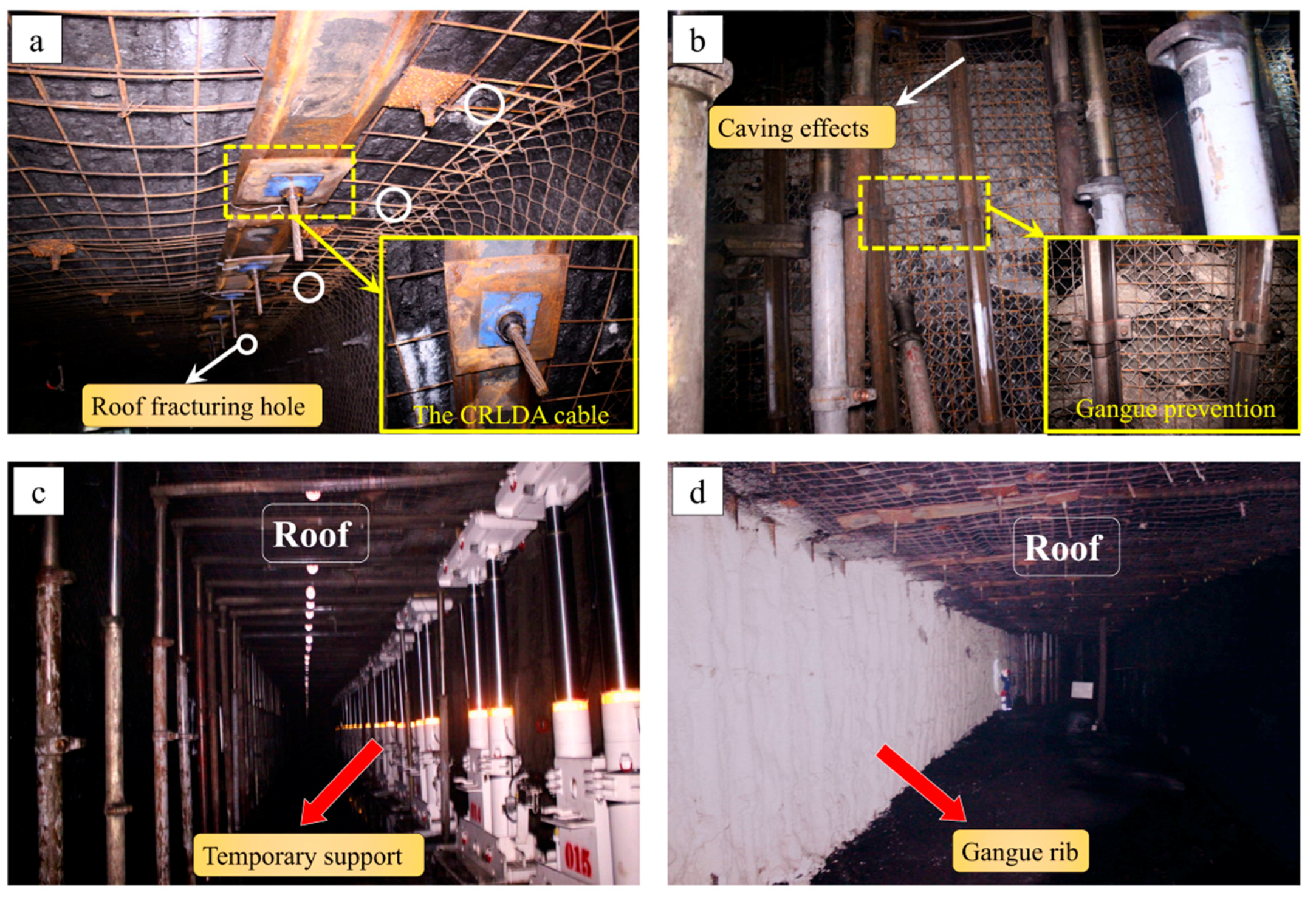
5.3. Entry Retaining Effects
The entry retaining photos are presented in Figure 22. As the mining face advanced, the gob roof gradually caved along the fracturing line, and the caved gangues formed a special entry wall. During caving and compaction of the gangues, gangue prevention structures and metal nets were used to prevent the gangues from extending out into the entry, as illustrated in Figure 22b. Once the pressure and displacement have stabilized, the temporary support was removed and reused. Observations show that the S1201 headentry was effectively maintained under the support of the CRLDA cable after the temporary support was removed. Finally, air leakage prevention materials were sprayed on the surface of the gangue rib, as shown in Figure 22d. Considering the ventilation and transportation cross-section requirements, the retained entry was able to meet the requirement of the next panel. The field monitoring indicated that the design was ergonomic and confirmed the feasibility of using the FRME approach in thick coal seams. However, it should be noted that since this was the first time for the FRME technique to be tested on a thick coal seam, the maximum allowable thickness of the coal seam needs to be further investigated.
6. Conclusions
In China, coal provides most of the energy for economic and industrial development. For sustainable utilization of limited coal resources, it is important to increase the coal recovery rate and improve entry stabilities. In the present study, an innovative approach for non-pillar mining, whose basic principle is the use of spontaneous caved gangues to maintain the entry, has been proposed.
Via structural and numerical modeling, it has been demonstrated that the stress concentration area was transferred to the gob area and that the retained entry was in a low-stress environment after adopting the FRME approach. Utilization of the load-bearing capacity of the surrounding rocks could effectively reduce the entry-in support and improve entry stability. Based on this idea, a corresponding design was put forward. In the design, a directional roof fracturing technique was used to promote gob roof caving, and the yieldable supports were specially designed to stabilize the entry roof.
To prove its feasibility, the FRME approach was tested in a thick coal seam. Field monitoring showed that the periodic weighting loads decreased and the periodic weighting intervals increased in the active mining panel after adopting the FRME approach. The mechanical and deformational characteristics of the entry roof indicated that the load-bearing capacity of the gangues was fully utilized in the FRME approach. The entry-in support first reached a constant resistance state and then yielded to share the overburden with the gangues. Finally, equilibrium was achieved under their cooperating supports. The motion state of the gob roof had important influences on the entry pressure. The fracturing of the main roof caused a pressure jump, whereas the compaction of the gangues caused a more gentle increase. Together, these results prove that the retained entry met the requirement of the next mining panel and confirm that the application of the FRME approach in the mining of thick coal seams is feasible, effective, and economical.
Acknowledgments
This work is supported by the National Natural Science Foundation of China (No. 51574248, No. 51674265) and the State Key Research Development Program of China (No. 2016YFC0600900), which are gratefully acknowledged.
Author Contributions
Manchao He and Yubing Gao conceived and designed the research. Yubing Gao performed the numerical simulation and field tests; Weili Gong and Jun Yang provided theoretical guidance in the research process; Yubing Gao analyzed the data and wrote the paper.
Conflicts of Interest
The authors declare no conflict of interest.
References
- Milici, R.C.; Flores, R.M.; Stricker, G.D. Coal resources, reserves and peak coal production in the United States. Int. J. Coal Geol. 2013, 113, 109–115. [Google Scholar] [CrossRef]
- Lechner, A.M.; Kassulke, O.; Unger, C. Spatial assessment of open cut coal mining progressive rehabilitation to support the monitoring of rehabilitation liabilities. Resour. Policy 2016, 50, 234–243. [Google Scholar] [CrossRef]
- Islavath, S.R.; Deb, D.; Kumar, H. Numerical analysis of a longwall mining cycle and development of a composite longwall index. Int. J. Rock Mech. Min. Sci. 2016, 89, 43–54. [Google Scholar] [CrossRef]
- He, M.C.; Zhu, G.L.; Guo, Z.B. Longwall mining “cutting cantilever beam theory” and 110 mining method in China-The third mining science innovation. J. Rock Mech. Geotech. Eng. 2015, 7, 483–492. [Google Scholar] [CrossRef]
- Suchowerska, A.M.; Merifield, R.S.; Carter, J.P. Vertical stress changes in multi-seam mining under supercritical longwall panels. Int. J. Rock Mech. Min. Sci. 2013, 61, 306–320. [Google Scholar] [CrossRef]
- Rezaei, M.; Hossaini, M.F.; Majdi, A. Development of a time-dependent energy model to calculate the mining-induced stress over gates and pillars. J. Rock Mech. Geotech. Eng. 2015, 7, 306–317. [Google Scholar] [CrossRef]
- Wang, S.L.; Hao, S.P.; Chen, Y.; Bai, J.B.; Wang, X.Y.; Xu, Y. Numerical investigation of coal pillar failure under simultaneous static and dynamic loading. Int. J. Rock Mech. Min. Sci. 2016, 84, 59–68. [Google Scholar]
- Zhang, N.; Yuan, L.; Han, C.L.; Xue, J.H.; Kan, J.G. Stability and deformation of surrounding rock in pillarless gob-side entry retaining. Saf. Sci. 2012, 50, 593–597. [Google Scholar] [CrossRef]
- Yang, H.Y.; Cao, S.G.; Wang, S.Q.; Fan, Y.C.; Wang, S.; Chen, X.Z. Adaptation assessment of gob-side entry retaining based on geological factors. Eng. Geol. 2016, 209, 143–151. [Google Scholar] [CrossRef]
- Li, X.H.; Ju, M.H.; Yao, Q.L.; Zhou, J.; Chong, Z.H. Numerical investigation of the effect of the location of critical rock block fracture on crack evolution in a gob-side filling wall. Rock Mech. Rock Eng. 2016, 49, 1041–1058. [Google Scholar] [CrossRef]
- Zhou, B.J.; Xu, J.H.; Zhao, M.S.; Zeng, Q.L. Stability study on naturally filling body in gob-side entry retaining. Int. J. Min. Sci. Technol. 2012, 22, 423–427. [Google Scholar] [CrossRef]
- Jiang, H.Q.; Miao, X.X.; Zhang, J.X.; Liu, S.W. Gateside packwall design in solid backfill mining–A case study. Int. J. Min. Sci. Technol. 2016, 26, 261–265. [Google Scholar] [CrossRef]
- Deng, Y.H.; Tang, J.X.; Zhu, X.K.; Fu, Y.; Dai, Z.L. Analysis and application in controlling surrounding rock of support reinforced roadway in gob-side entry with fully mechanized. Int. J. Min. Sci. Technol. 2010, 6, 841–845. [Google Scholar] [CrossRef]
- Tan, Y.L.; Yu, F.H.; Ning, J.G.; Zhao, T.B. Design and construction of entry retaining wall along a gob side under hard roof stratum. Int. J. Rock Mech. Min. Sci. 2015, 77, 115–121. [Google Scholar] [CrossRef]
- Zhang, Z.Z.; Bai, J.B.; Chen, Y.; Yan, S. An innovative approach for gob-side entry retaining in highly gassy fully-mechanized longwall top-coal caving. Int. J. Rock Mech. Min. Sci. 2015, 80, 1–11. [Google Scholar] [CrossRef]
- Yang, H.Y.; Cao, S.G.; Li, Y.; Sun, C.M.; Guo, P. Soft roof failure mechanism and supporting method for gob-side entry retaining. Minerals 2015, 5, 707–722. [Google Scholar] [CrossRef]
- Kang, H.P.; Wu, Y.Z.; Gao, F.Q. Deformation characteristics and reinforcement technology for entry subjected to mining-induced stresses. J. Rock Mech. Geotech. Eng. 2011, 3, 207–219. [Google Scholar] [CrossRef]
- Chen, Y.; Bai, J.B.; Yan, S.; Xu, Y.; Wang, X.Y.; Ma, S.Q. Control mechanism and technique of floor heave with reinforcing solid coal side and floor corner in gob-side coal entry retaining. Int. J. Min. Sci. Technol. 2012, 22, 841–845. [Google Scholar] [CrossRef]
- Gao, Y.B.; Guo, Z.B.; Yang, J.; Wang, J.W.; Wang, Y.J. Steady analysis of gob-side entry retaining formed by roof fracturing and control techniques by optimizing mine pressure. J. China Coal Soc. 2017, 42, 1672–1681. [Google Scholar]
- Hua, X.Z. Development status and improved proposals on gob-side entry retaining support technology in China. Coal Sci. Technol. 2006, 34, 78–81. [Google Scholar]
- Fei, X.M. The status of support technology on gob-side entry retaining roadway and existing problem discussion. Chin. Sci. Technol. Inf. 2008, 7, 48–49. [Google Scholar]
- Westergaard, H.M. Theory of Elasticity and Plasticity, 1st ed.; Harvard University Press: Cambridge, UK, 1953; pp. 105–163. [Google Scholar]
- Peng, S.S.; Chiange, H.S. Longwall Mining, 1st ed.; Wiley: New York, NY, USA, 1984; pp. 121–155. [Google Scholar]
- He, M.C.; Wang, J.; Sun, X.M.; Yang, X.J. Mechanics characteristics and applications of prevention and control rock bursts of the negative poisson’s ratio effect anchor. J. China Coal Soc. 2014, 39, 214–221. [Google Scholar]
- He, M.C.; Gong, W.L.; Wang, J.; Qi, P.; Tao, Z.G.; Du, S.; Peng, Y.Y. Development of a novel energy–absorbing bolt with extraordinarily large elongation and constant resistance. Int. J. Rock Mech. Min. Sci. 2014, 67, 29–42. [Google Scholar] [CrossRef]
- Su, C.D.; Gu, M.; Tang, X.; Guo, W.B. Experiment study of compaction characteristics of crushed stones from coal seam roof. Chin. J. Rock Mech. Eng. 2012, 31, 18–26. [Google Scholar]
- He, M.C.; Li, C.; Gong, W.L.; Wang, J.; Tao, Z.G. Support principles of NPR bolts/cables and control techniques of large deformation. Chin. J. Rock Mech. Eng. 2016, 35, 1513–1529. [Google Scholar]
- Qian, M.G.; Shi, P.W.; Xu, J.L. Mine Pressure and Strata Control, 1st ed.; China Mining University Press: Xuzhou, China, 2010; pp. 71–73. [Google Scholar]
- Palchik, V. Bulking factors and extents of caved zones in weathered overburden of shallow abandoned underground workings. Int. J. Rock Mech. Min. Sci. 2015, 79, 227–240. [Google Scholar] [CrossRef]
- Yavuz, H. An estimation method for cover pressure re-establishment distance and pressure distribution in the goaf of longwall coal mines. Int. J. Rock Mech. Min. Sci. 2004, 41, 193–205. [Google Scholar] [CrossRef]
Figure 1.
Three typical longwall mining schemes. (a) Large-pillar mining; (b) Small-pillar mining; (c) Zero-pillar mining.
Figure 1.
Three typical longwall mining schemes. (a) Large-pillar mining; (b) Small-pillar mining; (c) Zero-pillar mining.
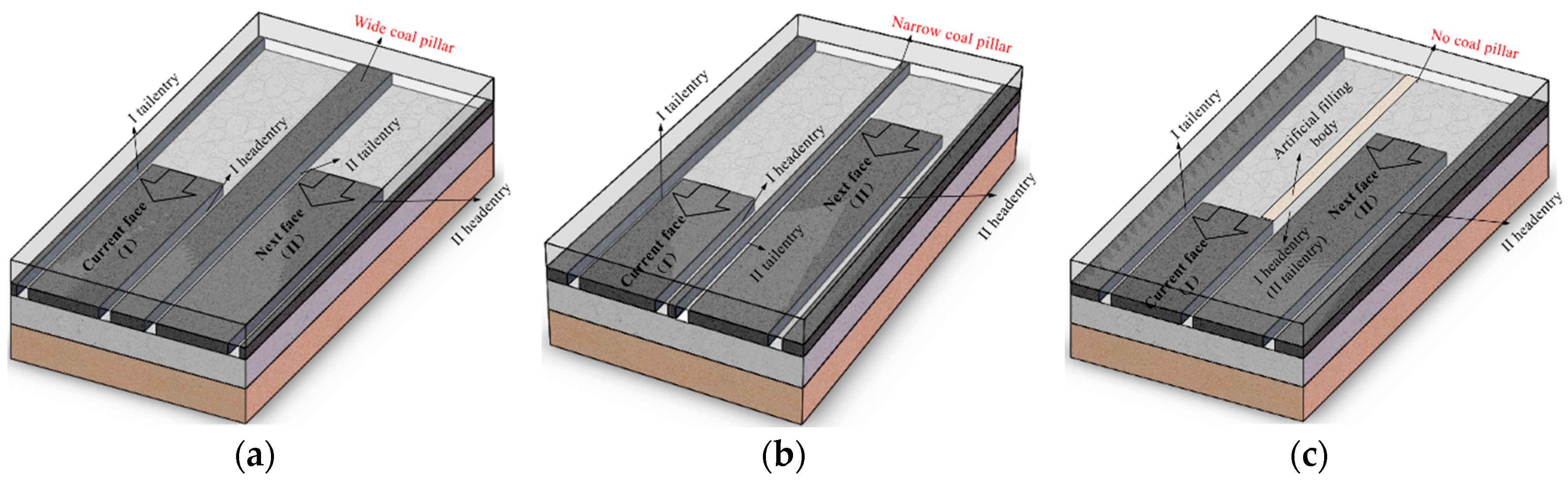
Figure 2.
Plane layout of the Fracturing Roofs to Maintain Entry (FRME) approach.
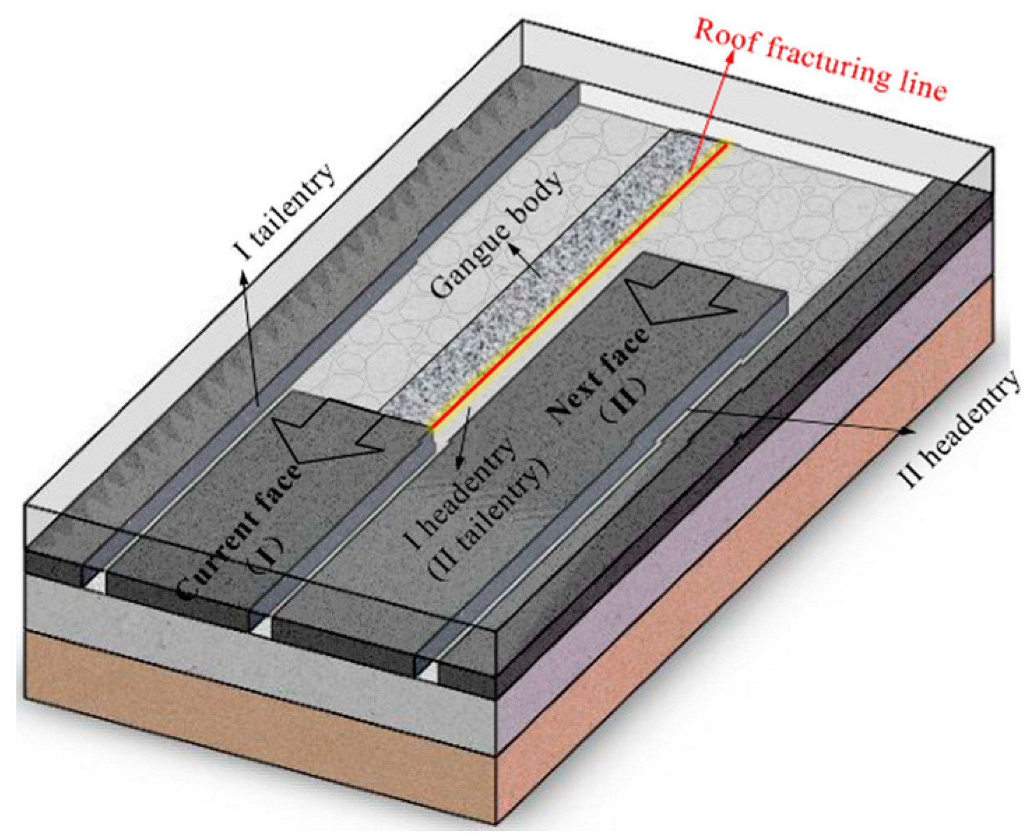
Figure 3.
Principle of the FRME approach: (a) No roof fracturing and reinforced support. The conventional anchor cables fail, and the entry collapses. (b) With roof fracturing and reinforced support. The entry is retained under active support.
Figure 3.
Principle of the FRME approach: (a) No roof fracturing and reinforced support. The conventional anchor cables fail, and the entry collapses. (b) With roof fracturing and reinforced support. The entry is retained under active support.

Figure 4.
Mechanical model of the FRME approach.

Figure 5.
Energy control of the directional roof fracturing technique.
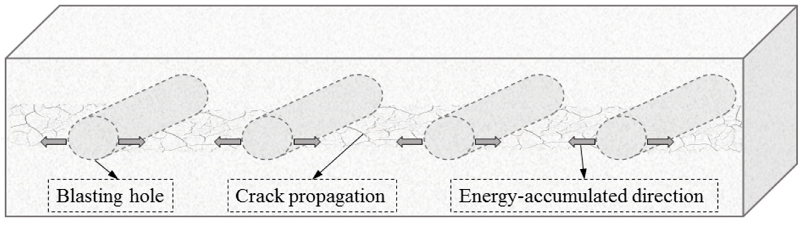
Figure 6.
Working principle of the constant resistance and large deformation anchor (CRLDA) cable: (a) Working process for stabilizing the entry roof; (b) Synergic bearing of the gangue body and CRLDA cable.
Figure 6.
Working principle of the constant resistance and large deformation anchor (CRLDA) cable: (a) Working process for stabilizing the entry roof; (b) Synergic bearing of the gangue body and CRLDA cable.
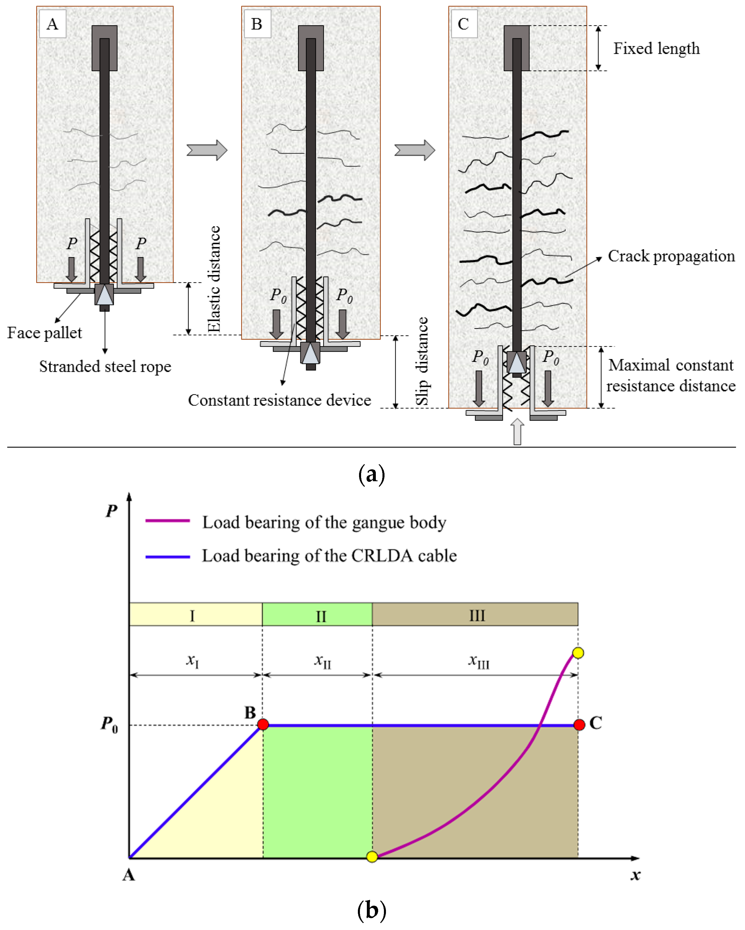
Figure 7.
Roof structure evolution during the FRME processes. (a) Stage I; (b) Stage II; (c) Stage III; (d) Stage IV.
Figure 7.
Roof structure evolution during the FRME processes. (a) Stage I; (b) Stage II; (c) Stage III; (d) Stage IV.

Figure 8.
Lithology of the rock layers near the coal.
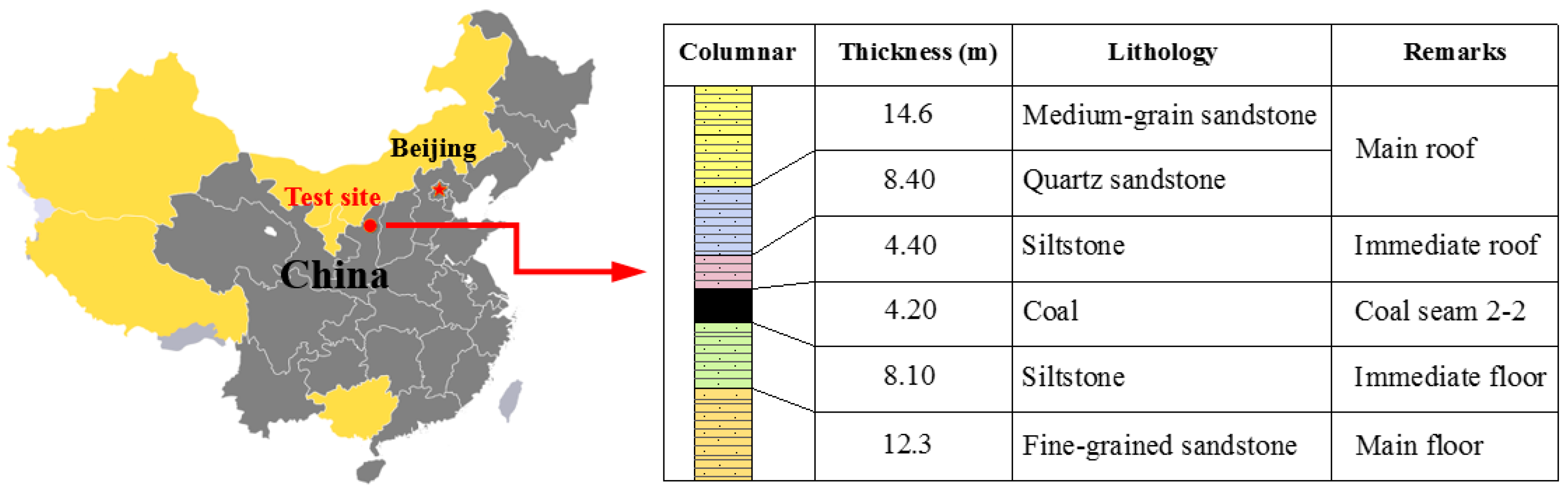
Figure 9.
Schematic diagram of the numerical model.
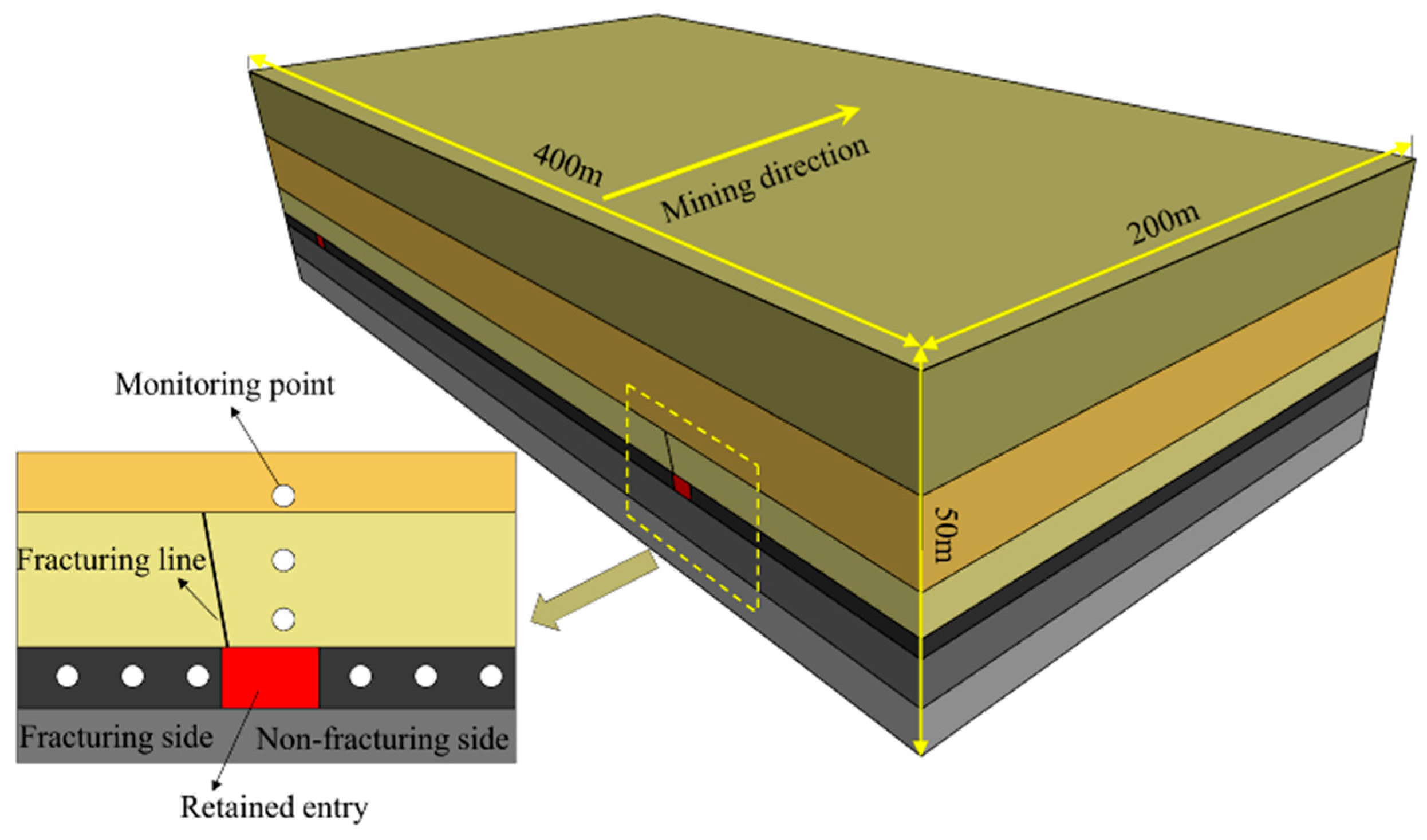
Figure 10.
Stress distributions on the entry sides: (a) Monitoring results for the non-fracturing side; (b) Monitoring results for the fracturing side.
Figure 10.
Stress distributions on the entry sides: (a) Monitoring results for the non-fracturing side; (b) Monitoring results for the fracturing side.
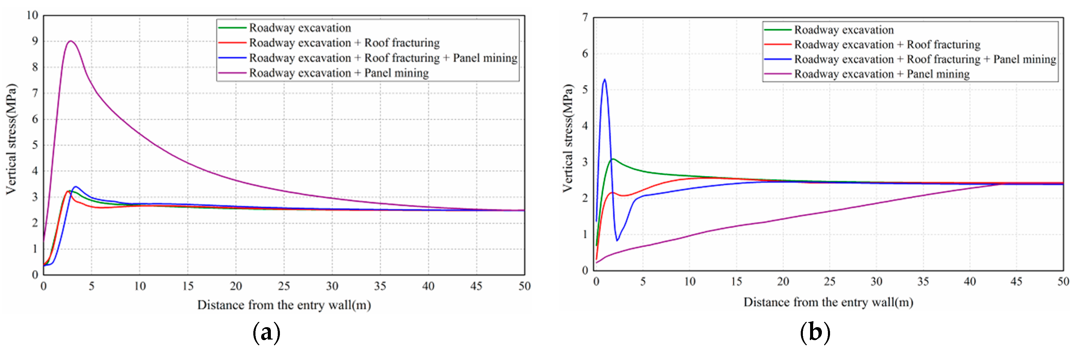
Figure 11.
Vertical stress variation on the entry roof with respect to the calculation steps: (a) The monitoring point was 5 m above the roof; (b) The monitoring point was 10 m above the roof; (c) The monitoring point was 20 m above the roof; (d) The monitoring point was 30 m above the roof.
Figure 11.
Vertical stress variation on the entry roof with respect to the calculation steps: (a) The monitoring point was 5 m above the roof; (b) The monitoring point was 10 m above the roof; (c) The monitoring point was 20 m above the roof; (d) The monitoring point was 30 m above the roof.
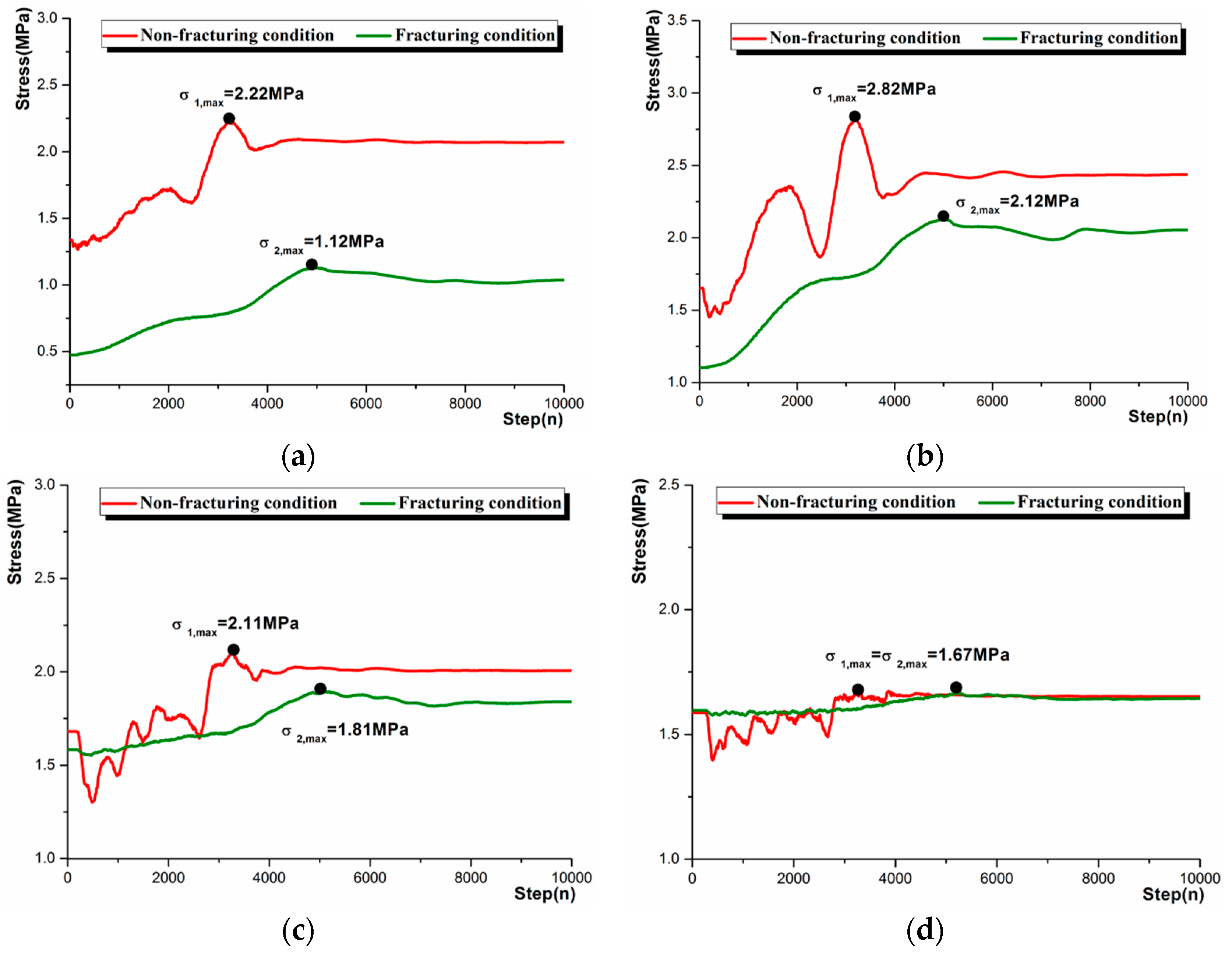
Figure 12.
Roof fracturing direction design: (a) The fracturing direction points to the entry roof; (b) The fracturing direction is perpendicular to the entry roof; (c) Rational fracturing direction for the S1201 headentry; (d) The fracturing angle is too large.
Figure 12.
Roof fracturing direction design: (a) The fracturing direction points to the entry roof; (b) The fracturing direction is perpendicular to the entry roof; (c) Rational fracturing direction for the S1201 headentry; (d) The fracturing angle is too large.

Figure 13.
Entry-in support design.
Figure 14.
Entry-side support design.

Figure 15.
Roof fracturing construction process: (a) Installing drill stems; (b) Drilling holes; (c) Blasting test; (d) Charging process; (e) Fracture distribution at the roof surface; (f) Fracture distribution in the holes.
Figure 15.
Roof fracturing construction process: (a) Installing drill stems; (b) Drilling holes; (c) Blasting test; (d) Charging process; (e) Fracture distribution at the roof surface; (f) Fracture distribution in the holes.
Figure 16.
Roof fracturing test and charging parameters.
Figure 17.
Construction process of the CRLDA cable: (a) Drilling cable holes; (b) Installing stranded steel rope and anchoring resin; (c) Installing cable accessories; (d) Imposing pre-tightening force; (e) Installing complete.
Figure 17.
Construction process of the CRLDA cable: (a) Drilling cable holes; (b) Installing stranded steel rope and anchoring resin; (c) Installing cable accessories; (d) Imposing pre-tightening force; (e) Installing complete.
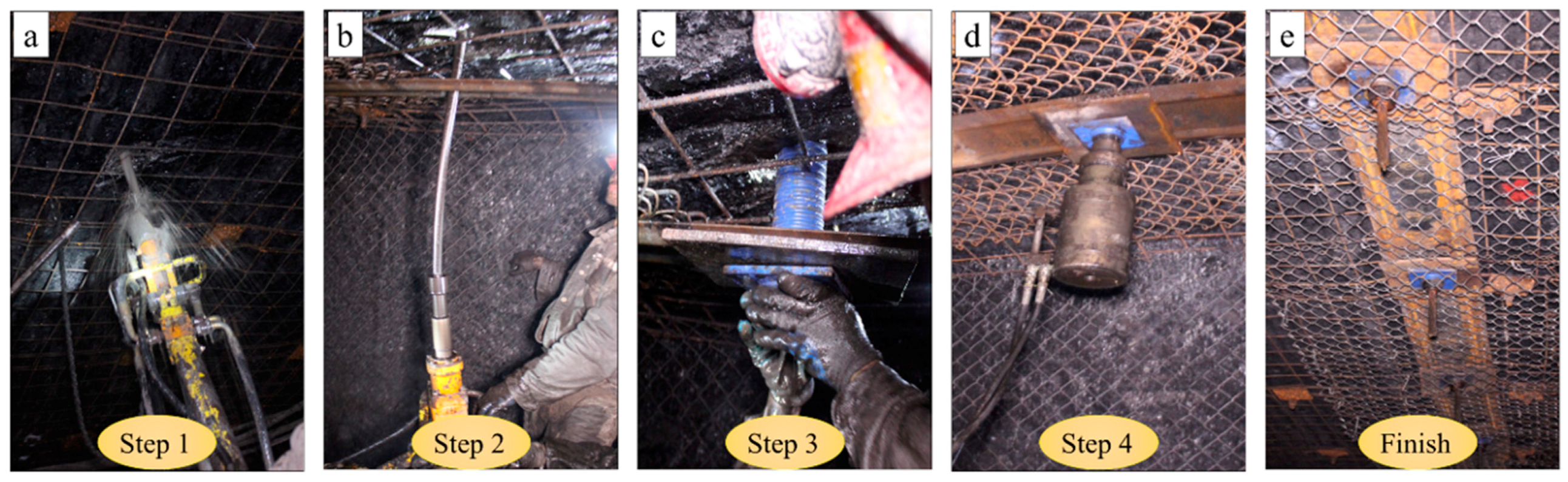
Figure 18.
Sketch of the field monitoring and apparatus: (a) Monitoring apparatus for roof pressure of the S1201 panel; (b) Monitoring apparatus for roof pressure of the S1201 headentry; (c) Monitoring apparatus for convergence. The pressure changes in position A, B and, C measure the bearing load of hydraulic supports of the active working panel. The distance and pressure change between D pin and D′ pin, E pin, and E′ pin in vertical direction measure the convergence and pressure of roof to floor. The distance change between F pin and F′ pin in horizontal direction measures the convergence of gangue rib to coal rib. The pressure change in F′ pin measures the lateral pressure of gangues.
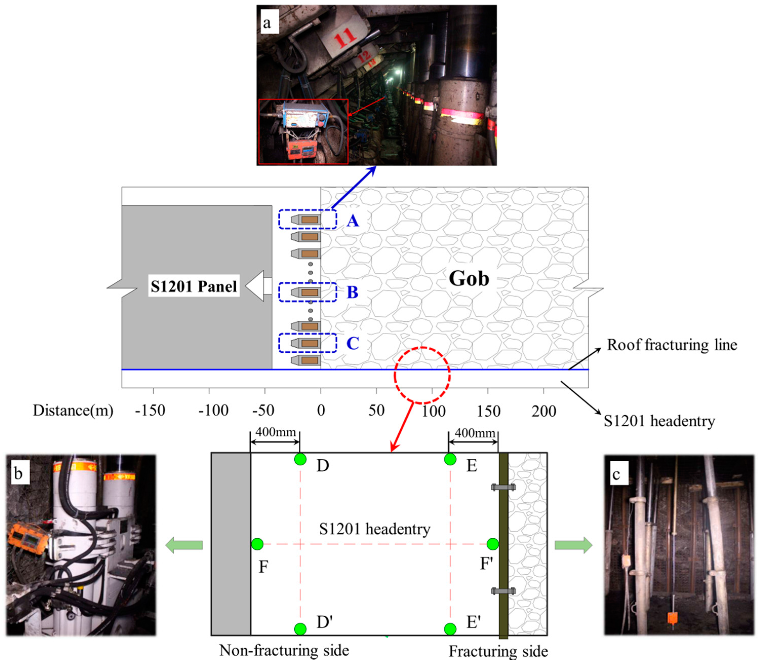
Figure 19.
Monitoring results of the roof pressures in the S1201 working panel.
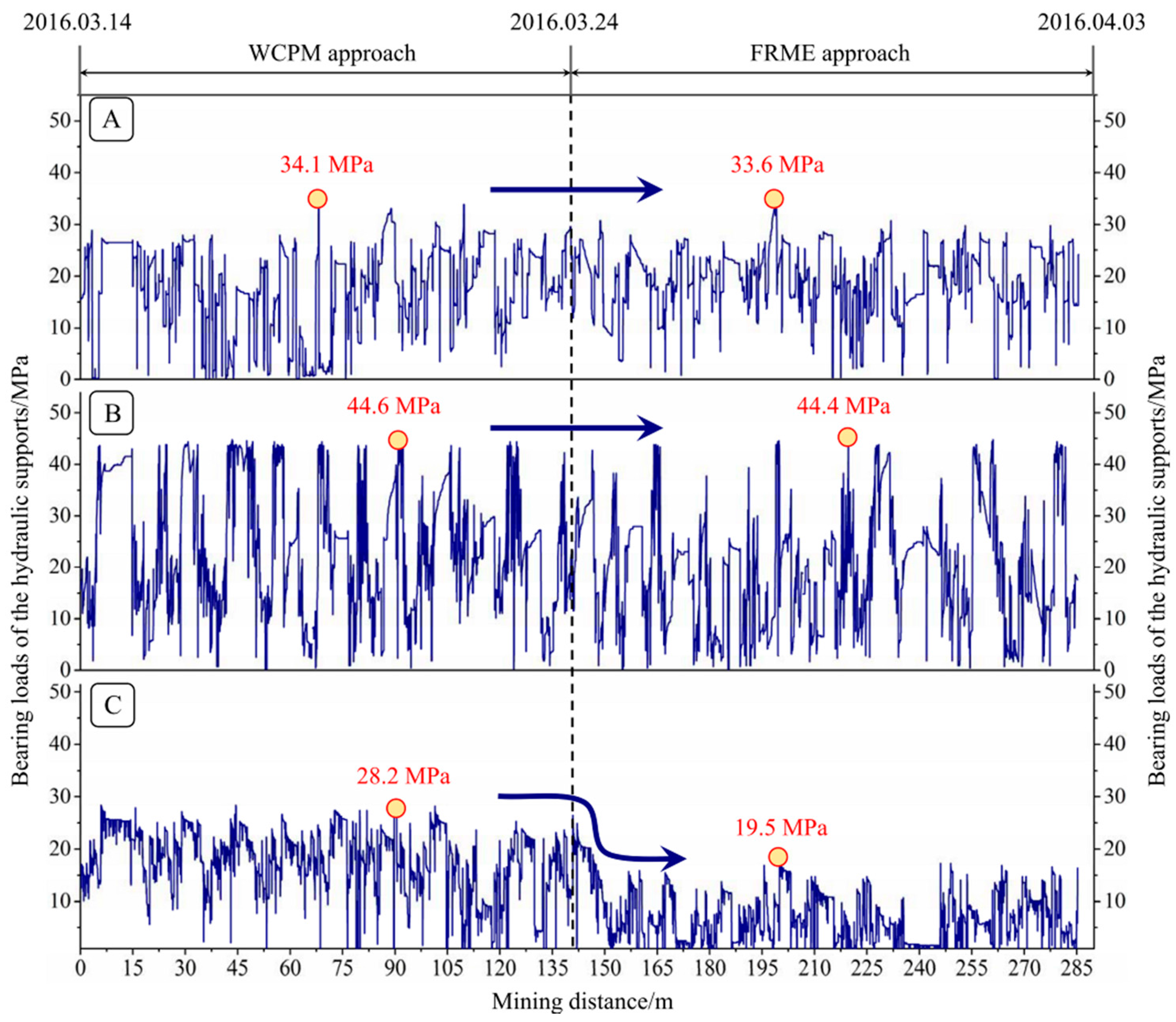
Figure 20.
Monitoring results of the roof and lateral pressures in the S1201 headentry. The red line shows the variation in the lateral pressure, and the blue line presents the monitoring results of the roof pressure.
Figure 20.
Monitoring results of the roof and lateral pressures in the S1201 headentry. The red line shows the variation in the lateral pressure, and the blue line presents the monitoring results of the roof pressure.
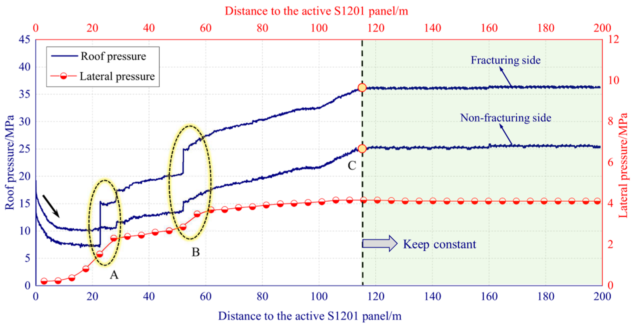
Figure 21.
Monitoring results of the entry deformation: (a) Convergences and convergence rates of the roof to floor at the fracturing and non-fracturing sides; (b) Convergence and convergence rate of the gangue rib to coal rib.
Figure 21.
Monitoring results of the entry deformation: (a) Convergences and convergence rates of the roof to floor at the fracturing and non-fracturing sides; (b) Convergence and convergence rate of the gangue rib to coal rib.
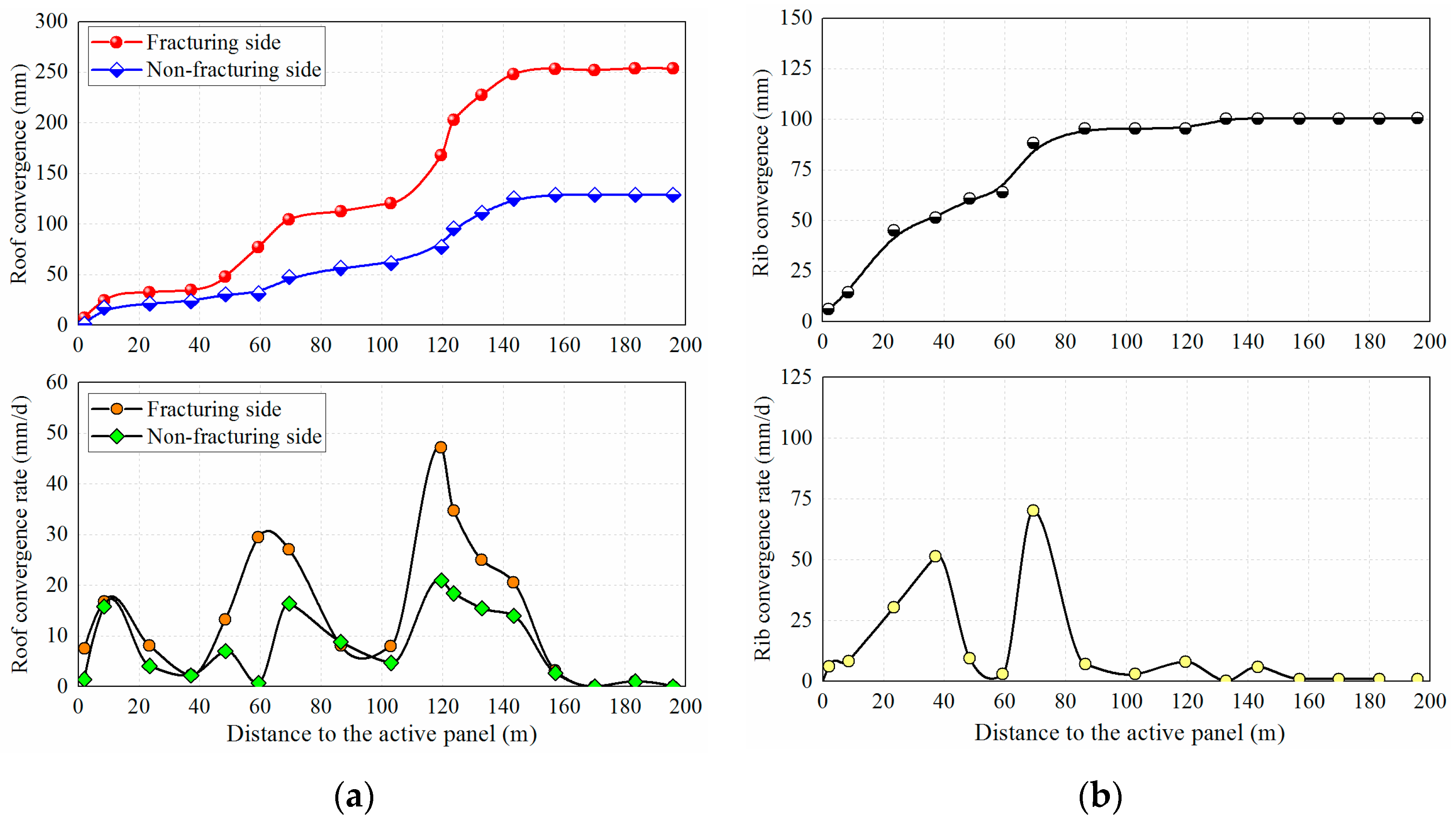
Figure 22.
Entry retaining effects with the FRME approach: Photo (a) shows the construction effects of the CRLDA cable. Photo (b) shows the caving and gangue prevention effects after mining. Photos (c) and (d) present the cross sections of the retained entry before and after removing the temporary supports, respectively. In photo (d), the gangue rib had been blocked up using a high polymer material to prevent gob air leakage.


Table 1.
Rock strata properties used in the numerical model.
| Rock Strata | Density (kg/m3) | Uniaxial Compressive Strength (MPa) | Young’s Modulus (GPa) | Friction Angle (deg.) | Cohesion (MPa) |
|---|---|---|---|---|---|
| Medium sandstone | 2500 | 69.34 | 15.86 | 37 | 2.24 |
| Quartz sandstone | 2700 | 81.32 | 17.78 | 43 | 3.78 |
| Siltstone | 2400 | 38.65 | 14.33 | 34 | 1.87 |
| Coal | 1400 | 17.78 | 3.535 | 31 | 1.52 |
| Siltstone | 2400 | 38.65 | 14.33 | 34 | 1.87 |
| Fine sandstone | 2600 | 78.35 | 16.56 | 39 | 3.56 |
© 2017 by the authors. Licensee MDPI, Basel, Switzerland. This article is an open access article distributed under the terms and conditions of the Creative Commons Attribution (CC BY) license (http://creativecommons.org/licenses/by/4.0/).
Share and Cite
MDPI and ACS Style
He, M.; Gao, Y.; Yang, J.; Gong, W. An Innovative Approach for Gob-Side Entry Retaining in Thick Coal Seam Longwall Mining. Energies 2017, 10, 1785. https://doi.org/10.3390/en10111785
AMA Style
He M, Gao Y, Yang J, Gong W. An Innovative Approach for Gob-Side Entry Retaining in Thick Coal Seam Longwall Mining. Energies. 2017; 10(11):1785. https://doi.org/10.3390/en10111785
Chicago/Turabian StyleHe, Manchao, Yubing Gao, Jun Yang, and Weili Gong. 2017. "An Innovative Approach for Gob-Side Entry Retaining in Thick Coal Seam Longwall Mining" Energies 10, no. 11: 1785. https://doi.org/10.3390/en10111785
Note that from the first issue of 2016, this journal uses article numbers instead of page numbers. See further details here.