Enhancement of Condensation Heat Transfer Rate of the Air-Steam Mixture on a Passive Condenser System Using Annular Fins


1
Department of Nuclear and Energy Engineering, Jeju National University, 66 Jejudaehakno, Jeju-si, Jeju 63243, Korea
2
School of Energy Systems Engineering, Chung-Ang University, Seoul 156-756, Korea
3
Department of Mechanical Engineering, Jeju National University, 66 Jejudaehakno, Jeju-si, Jeju 63243, Korea
*
Author to whom correspondence should be addressed.
Energies 2017, 10(11), 1777; https://doi.org/10.3390/en10111777
Submission received: 12 August 2017
/
Revised: 31 October 2017
/
Accepted: 2 November 2017
/
Published: 4 November 2017
(This article belongs to the Section I: Energy Fundamentals and Conversion)
Abstract
:This paper presents an experimental investigation on the enhancement of the heat transfer rate of steam condensation on the external surfaces of a vertical tube with annular fins. A cylindrical condenser tube, which is 40 mm in outer diameter and 1000 mm in length, with annular disks of uniform cross-sectional area is fabricated in the manner of ensuring perfect contact between the base surface and fins. A total of 13 annular fins of 80 mm diameter were installed along the tube height in order to increase the effective heat transfer area by 85%. Through a series of condensation tests for the air-steam mixture under natural convection conditions, the heat transfer data was measured in the pressure range of between 2 and 5 bar, and the air mass fraction from 0.3 to 0.7. The rates of heat transfer of the finned tube are compared to those that are measured on a bare tube to demonstrate the enhanced performance by extended surfaces. In addition, based on the experimental results and the characteristics of steam condensation, the applicability of finned tubes to a large condenser system with a bundle layout is evaluated.
1. Introduction
Condensation plays an important role to increase the energy efficiency in industries. Therefore, the condensation process is essential for refrigeration/air conditioning, aerospace, nuclear power, and many other industries.
In the nuclear power industry, the importance of heat transfer by steam condensation has been emphasized more since the Fukushima accident. As the accident progressed due to a loss of all electrical power, it has been recommended thereafter that the mitigation features for an accident be passive to assure a reliable performance [1], and steam condensation can be adopted as a heat transfer mode to naturally remove an accumulating thermal energy in an enclosure. To prevent an incident such as the Fukushima accident, the passive containment cooling system can be employed to preserve the integrity of the containment. The passive containment cooling system (PCCS) is an advanced safety system to guarantee the structural integrity of the containment using condensation heat transfer phenomena, as shown in Figure 1. Once the design basis accidents, such as the loss of coolant accident (LOCA) and the main steam line break (MSLB,) occur in a nuclear power plant, the released steam forms a gas mixture with air, and it is condensed on the outer surface of a tube bundle in the PCCS. Thus, the heat removal rate of the condenser tubes in the PCCS is dominated by steam condensation in the presence of a noncondensable gas under natural convection conditions. With regard to the containment cooling, many researchers have investigated the steam condensation in the presence of a noncondensable gas [2,3,4,5,6,7,8,9,10,11,12,13].
Depending on the design criteria of the PCCS, a vast heat transfer area may be required for the decay heat removal. For example, if the PCCS has to meet the requirement that it removes all of the decay heat at five minutes after the reactor shutdown, its capacity has to reach 3% of the rated thermal power of the reactor; it comes to about 85 MW for a nuclear power plant of 1000 MWe. To achieve such a great heat flow from the containment, the PCCS has to incorporate a number of lengthy condenser tubes for sufficient surface area of heat transfer. One feasible approach to increasing the heat transfer capacity of the PCCS is to introduce extended surfaces for the condenser tubes. Through increasing the heat transfer rate using fins, the required number or length of condenser tubes can be greatly reduced.
Several experimental and analytical studies have been carried out for condensation heat transfer on the finned tubes. Liu [5] conducted external condensation experiments using two types of finned tubes: longitudinal and annular. The experimental results did not represent a sufficient enhancement of heat transfer, as expected by an analytical approach, due to an unexpected thermal resistance created between the tube surface and fins. Tong et al. [14,15] discussed the experimental results obtained from the longitudinal finned tube and the pin-fin tube. Local temperature profiles around the test tube were obtained, and the condensation heat transfer capacity was compared to that of a smooth tube. Recently, Furuichi et al. [16] measured the heat transfer coefficient of the vertical tube with the liquid-film scattering rings that were applicable for the intermediate heat exchanger (IHX). The experiments were conducted using four sets of IHX tubes under pure steam conditions, and the effect of the rings on the heat transfer was discussed from observation of the condensate liquid.
As analytical studies, Mori et al. [17] investigated an optimum surface geometry of vertical condenser tubes, which have an array of longitudinally parallel tiny fins and a circular disk attachment. The effect of surface tension on condensation was taken into account, and the optimum fin shape, fin pitch, and spacing of the disk were found. However, the effect of circular disks was not evaluated independently. Herranz et al. [18] proposed a theoretical model that was capable of predicting the condensation of a cross-flow air-steam mixture on a single horizontal finned tube. Munoz-Cobo et al. [19] presented a mechanistic model that predicts the steam condensation on containment finned tube heat exchangers in the presence of noncondensable gases and aerosols.
The literature review reveals that the previous experiments of the finned tube to evaluate the enhancement of heat transfer have been focused on the horizontal tube problems that were selected to prevent the continuous accumulation of liquid condensate along the wall. However, the horizontal finned tube is not an appropriate choice for the PCCS, because the condenser tubes are deployed around the inner periphery of the limited space in the containment. Thus, this study investigates the enhancement of the rate of condensation heat transfer on a vertical condenser tube by the finned surfaces. As a fin configuration, the annular fins with a uniform cross-sectional area were chosen referring to the experimental results of Liu [5], which will be discussed in Section 2.1. The rate of heat transfer of the annular finned tube was compared to that of the bare rod obtained in identical conditions to estimate the fin thermal performance. On the basis of the experimental results from this study and previous researches, the applicability of fins to the prototypical PCCS was also evaluated.
2. Experiment
The reference test for this study [20], which provides the rate of heat transfer for the bare tube, has measured the condensation heat transfer coefficients in the presence of air on a vertical cylinder under natural convection conditions. The experiments were conducted in a pressure range of 2–5 bar and an air mass fraction ranging from 0.10 to 0.88. The effects of the major parameters on the condensation heat transfer were evaluated in the test. A new empirical correlation was developed in terms of dimensionless numbers for the vapor-gas boundary layer and its prediction was validated with experimental data.
The experimental work of this study was also conducted at the Jeju National University (JNU) condensation test facility of reference [20], with an exception that the test section was replaced to encompass the annular finned tube. Details of the experimental apparatus, including the newly fabricated finned tube, and the data reductions are as follows.
2.1. Experimental Apparatus
As described in Figure 2, the experimental loop consisted of two sections: the condensation section and the cooling section. The condensation section included a chamber with the installed condenser tube inside, a steam generator, a condensate tank, and a recirculation pump. The cooling section had a water storage tank and a pump. The chamber diameter was 609 mm and its height was 1950 mm. A vertical finned tube with 1000 mm in the effective length was installed inside of the chamber. Both the chamber and the condenser tube were constructed from type 304 stainless steel.
Figure 2 also describes the flow of vapor and coolant with different color. At the early stage of each run, the predetermined amount of air was injected into the chamber. Then, its total mass remained unchanged during the experiment since air was not condensed on the tube, nor released out of the chamber. The saturation steam was generated through submerging heaters in the steam generator, and was sent to the lower part of the chamber. To establish the steady state in the test section, the rate of steam supply was adjusted so that the mass and energy balance of steam could be met in the chamber. The condensate flowed to the condensate tank, and was recirculated to the steam generator to maintain the water inventory.
The air content inside the chamber was found from the measured temperature of the gaseous mixture and the total pressure. The steam was assumed to be in a saturated state, and thermal equilibrium with air. Then the partial pressure of steam corresponded to the saturation pressure, and the partial pressure of air was obtained by using the Dolton’s law of partial pressure.
A preliminary test was conducted to confirm the heat loss of the experimental facility. Prior to performing the preliminary test, all of the experimental apparatuses were insulated using glass fiber. All of experimental facility, such as a steam generator, a chamber, a steam supply line, and a recirculation line that was filled with water. After the filling water up, the water was heated up and the heat loss was calculated taking into account the temperature reduction rate with the overall water inventory of the loop. From the preliminary test, the total heat loss was measured as 2.3 kW.
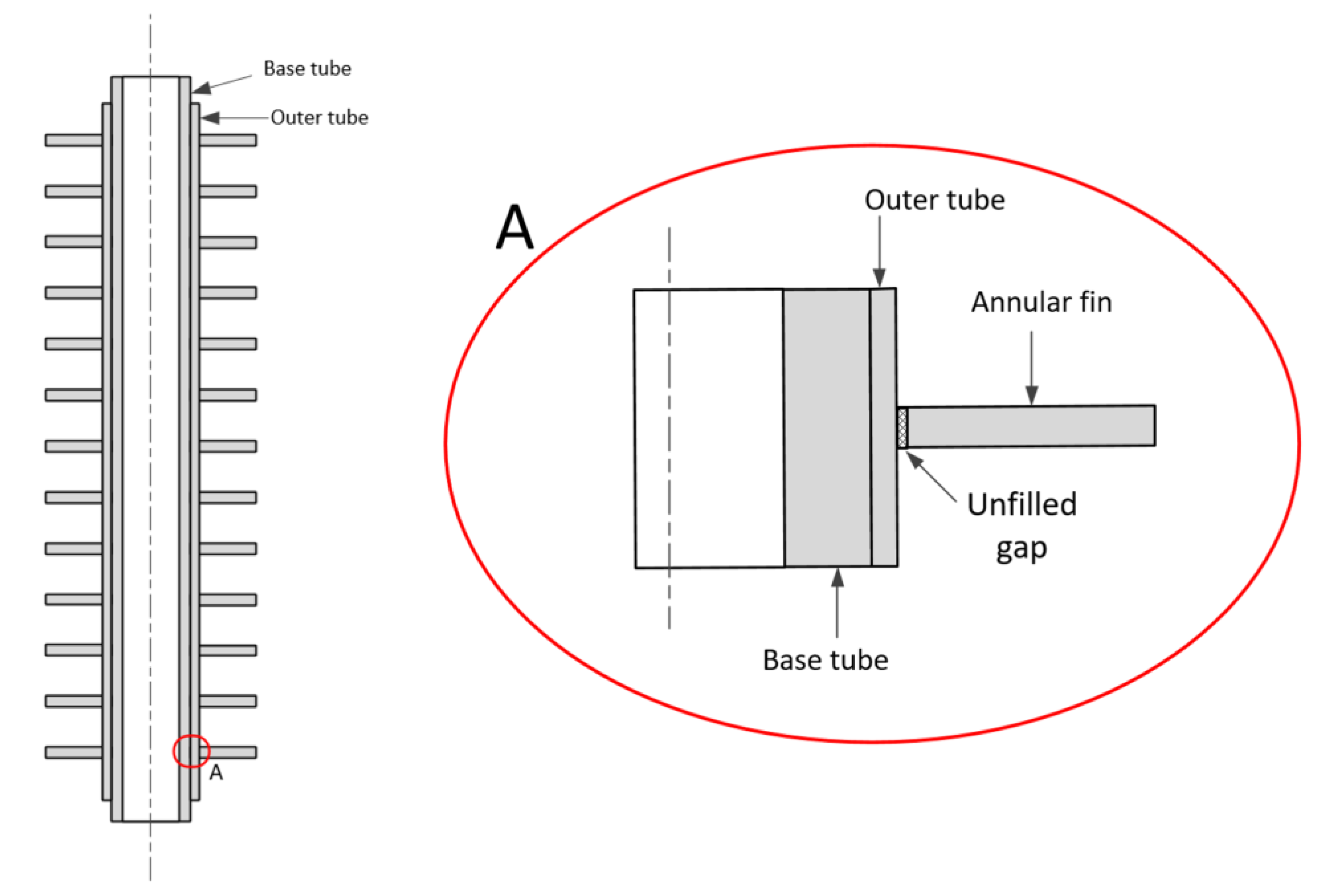
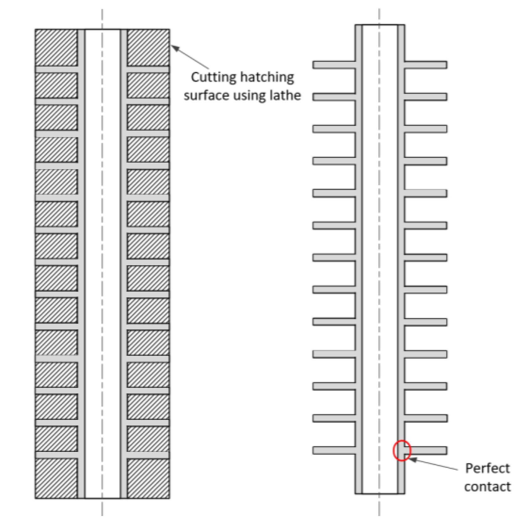
In designing a finned tube, the experimental study of Liu [5] on finned tubes was reviewed and considered. In the work, the analytical enhancement factor is calculated for the heat transfer rate of tubes with longitudinal and annular fins. They fabricated both types of finned tubes and measured the total heat transfer rate, varying the pressure and the air fraction. It was revealed that the experimental enhancement factor was lower than the analytical results because the contact thermal resistance occurred between the tube surface and fins during the fabrication. It states that the longitudinal fins were soft soldered, and the annular fins were mechanically pressed on to the base tube. Figure 3 illustrates that some unfilled gaps could be formed between the base tube and annular fins. Helically wrapped on the base tube, the annular fins did not make perfect contact with the base surface, which created an unexpected contact resistance at the interface.
In this study, both longitudinal and annular finned tubes were also regarded as feasible options for the PCCS. Even though both fins increase the effective surface area of the condenser tube, one has to take into account their adverse effect on the flow of adjoining air-steam mixture when these finned tubes are assembled to a bundle arrangement. One of the major concerns for the longitudinal fins is that they will severely impede the radial diffusion of the gaseous mixture to the condensing surface. Note that the steam to be condensed is carried from the free stream to the surface by radial diffusive flow. If the heat exchanger of the PCCS consists of a bundle of the longitudinal finned tubes, then the condenser tubes at the edges will substantially retard the influx of the vapor-gas mixture to the interior tubes.
On the other hand, when the annular fins are applied, they would disrupt the parallel flow of the gaseous mixture along the condenser tube. Under natural convection conditions, the air-steam mixture flows downwards in the vicinity of the condensing surface. As this convective flow is inhibited, the heat and mass transfer coefficient are to be reduced. However, even if the bundles of annular finned tubes are employed, the radial diffusive flow of air-steam mixture can reach to all interior condenser tubes. From these considerations, the annular fin of uniform cross-sectional area was chosen as the final fin configuration.
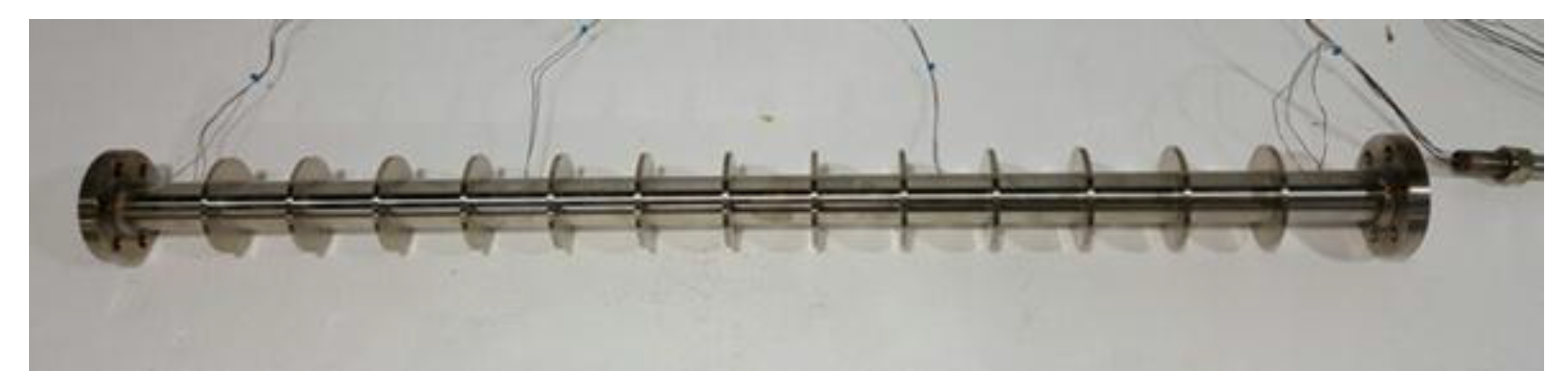
To eliminate the problem of the contact thermal resistance, as discussed in the work of Liu et al., the annular finned tube was fabricated by means of the turning process, as described in Figure 4. From a sufficiently thick tube with the same diameter as the designed annular disk, the portions other than the fins (hatched region in Figure 4) were cut off through a lathe turning so that the perfect contact of fins to the base surface can be assured. The diameter of the base tube was determined to be 40 mm, which is the same as that of the condenser tube used in reference [20], and its effective length was 1000 mm. The diameter of the outer edge of the designed annular fin was 80 mm; it is the maximum diameter when the PCCS tube bundle is designed to have the pitch-to-diameter of 2.0. The annular disk was 5-mm thick, and the fin pitch was fixed at 70 mm. A total of thirteen annular fins were installed on the condenser tube, thereby increasing the heat transfer area by 84%. Figure 5 shows the photograph of the annular finned tube that was used in this study.
The theoretical fin efficiency of the designed tube was evaluated. The fin efficiency of the single annular fin, ηf, is expressed as [21]:
where
In Equations (1) and (2), r1 denotes the radius of the bare tube, and r2c the corrected tip radius of the form. h and k represent the heat transfer coefficient and the thermal conductivity of the fin, respectively. Equation (1) shows that the fin efficiency is expressed in terms of the Bessel functions of the first and the second kinds. For the designed array of annular fins, the overall fin efficiency, η0, is given as:
where Af and At denote the surface area of the single fin, and the total surface area with N fins in the array, respectively. Figure 6 presents the calculated overall fin efficiency at 4 bar where the heat transfer coefficients measured from the bare tube varies over 260–790 W/(m2·K). The fin efficiency analysis reveals that the overall fin efficiency for the design of the finned tube used in this study ranged from 0.65 to 0.73.
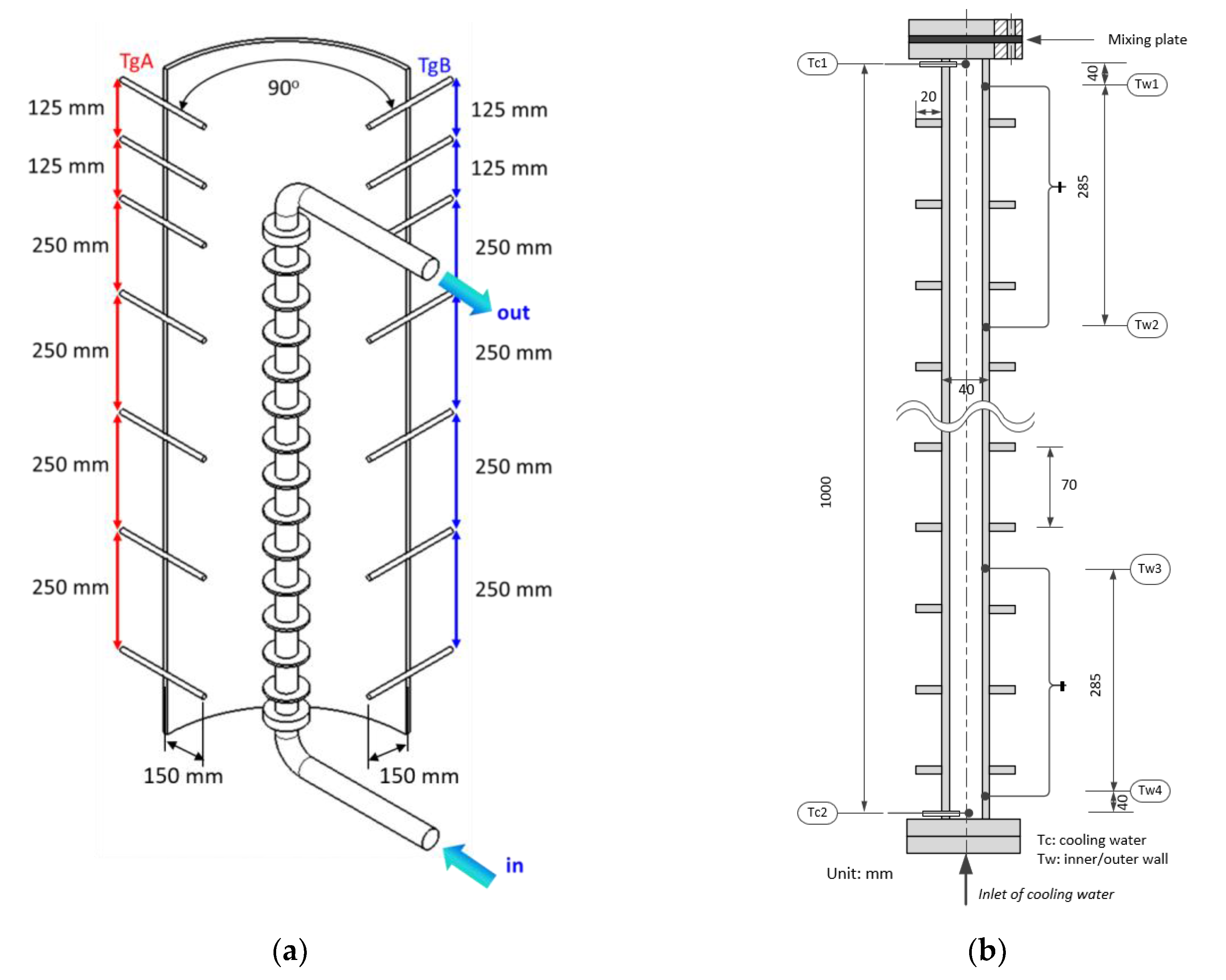
Figure 7 describes the location of the thermocouples in the condenser tube and the chamber. In order to measure the internal gas mixture distribution, fourteen thermocouples were installed inside the chamber. Each set consisted of seven thermocouples that were vertically arranged along the tube height, and these two sets has an azimuthal interval of 90 degrees. These thermocouples were located at the midpoint of the centerline and the inner wall of the chamber; that is, their sheath tips were inserted 150 mm into the chamber. A total of ten K-type thermocouples were installed on the finned tube. Two thermocouples at the top and the bottom penetrating the tube wall measure the coolant temperature at the center of the channel. Eight grounded thermocouples were embedded to the base tube by means of silver soldering to measure the temperature of the inner and outer walls at four elevations. The thermocouples for inner and outer surfaces were positioned 4.5 mm and 1.0 mm deep from the base surface, respectively.
Using the fabricated finned tube, a series of condensation tests were conducted in the presence of air under natural convection conditions. That is, while air with a prescribed partial pressure was present in the chamber, steam was continuously supplied to the lower section to sustain an overall heat balance. Table 1 presents the test matrix of the condensation tests. The rate of condensation heat transfer was measured in the pressure range from 2 to 5 bar, and the air mass fraction was adjusted from 30% to 70%. The mean temperature of the base surface was also controlled to establish the similar thermal conditions on which the condensation tests with the bare tube [20] were performed.
2.2. Data Reduction
Since the sheath tips of thermocouples for wall temperatures were embedded inside the interior tube wall, the measured values are corrected to the real surface temperatures as follows:
where, and denote the measured outer wall temperature and inner wall temperature by using thermocouples, respectively. and denote the corrected outer wall temperature and inner wall temperature, respectively. They represent the true value of the inner and outer wall temperature obtained on the basis of the heat diffusion method. and represent the inner and outer location of the installed thermocouple, respectively; and represent the inner and outer radius of the condenser tube, respectively. From the corrected surface temperatures, the local heat flux is calculated as follows:
where denotes the thermal conductivity of the wall.
The rate of condensation heat transfer is obtained from the heat removal rate by the coolant through the condenser tube in a steady state as:
where , , and are the mass flow rate of coolant, the specific heat, the outlet temperature, and inlet temperature of coolant, respectively.
The measurement of uncertainties for the total heat transfer rates are calculated by:
where the uncertainty of the coolant temperature rise, , is defined as follows:
The measurement of uncertainties of instruments are summarized in Table 2. In all of the tests, the mass flow rate of the coolant was quite high to maintain the temperature of the outer wall uniform [20]. As the rise of the coolant temperature is low, the uncertainty in evaluation of the heat removal rate, represented by Equation (7), could be fairly high. To prevent this, the thermocouples for measuring fluid (coolant) temperature was specially calibrated by using a thermostat with an error of 0.2 K. The results of the uncertainty analysis revealed that the maximum uncertainty of the heat transfer rate was 11.7%.
3. Results and Discussion
3.1. Experimental Results
Through visualization windows installed in the chamber, the flow pattern of falling condensate liquid around the annular fins was observed. Figure 8 is the photographs of the condensate liquid that were captured at 0.75 m from the top of the condenser tube when the pressure was 4 bar and the air mass fraction was 44.7%. The time interval between the images (a) to (c) is 10 ms.
As shown in Figure 8d, a thick liquid film was retained on the upper surfaces of the annular disk due to the surface tension. As the condensate from the upper section flowed downwards along the tube surface and coalesced with the liquid film on the fin, it resulted in flooding. Once flooding occurred, some condensate scattered from the condenser tube to fall onto the test chamber floor and other cascaded condensate flowed through the lower surface of the disk to spatter on the annular fin immediately below. The flooding occurred periodically. Figure 8a–c present well that the inflow of the condensate from the upper fin of the image resulted in flooding of the liquid film on the lower fin. After flooding, the remaining condensate liquid was stored stably on the upper side of the annular disk. These flooding phenomena occurred periodically during the experiments.
The above visualization results revealed that the condensation mechanism on the finned tube was affected by the flooding effect of the condensate. The annular fin functioned positively in a view of heat transfer as it impeded the continuous accumulation of the condensate liquid along the tube wall, whereas large thermal resistance would exist on the upper side of each annular fin, thereby retarding the rate of heat transfer locally.
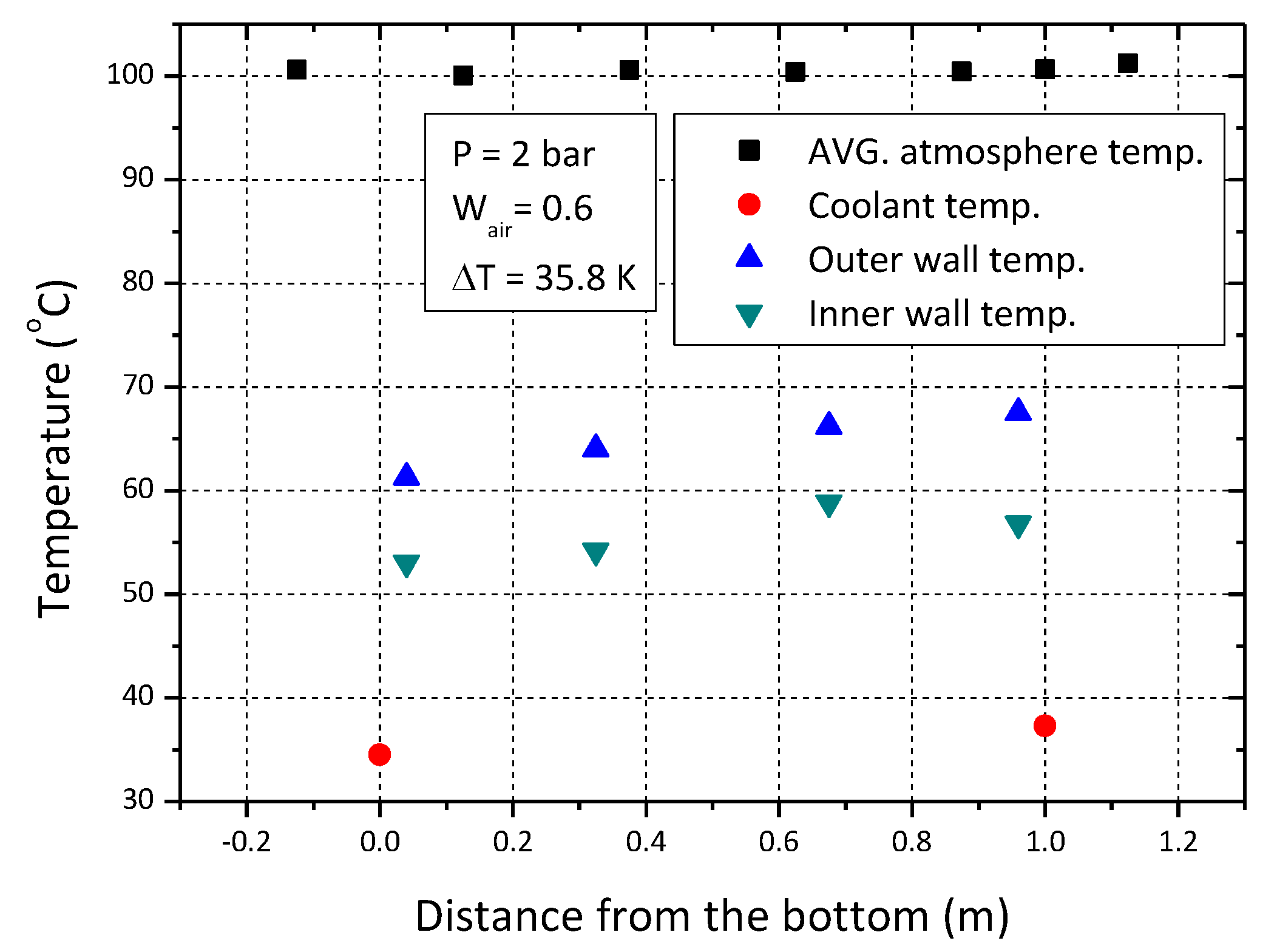
Figure 9 presents typical temperature distribution inside the chamber for the air mass fraction of 0.6 at 2 bar. The wall subcooling was 35.8 K. It did not exhibit thermal stratification of the air-steam mixture inside the chamber; the temperature difference according to the elevation was within 1.6 K during all of the experiments. The naturally convective flow of the gaseous mixture inside the chamber mixed the vapor and gas species well, establishing a uniform distribution along the height. Furthermore, the maximum difference between the temperatures of the outer surface along the base tube was at most 6.2 K. Therefore, the wall temperature was also well controlled to have nearly isothermal conditions by adjusting the coolant flow rate high through the condenser tube.
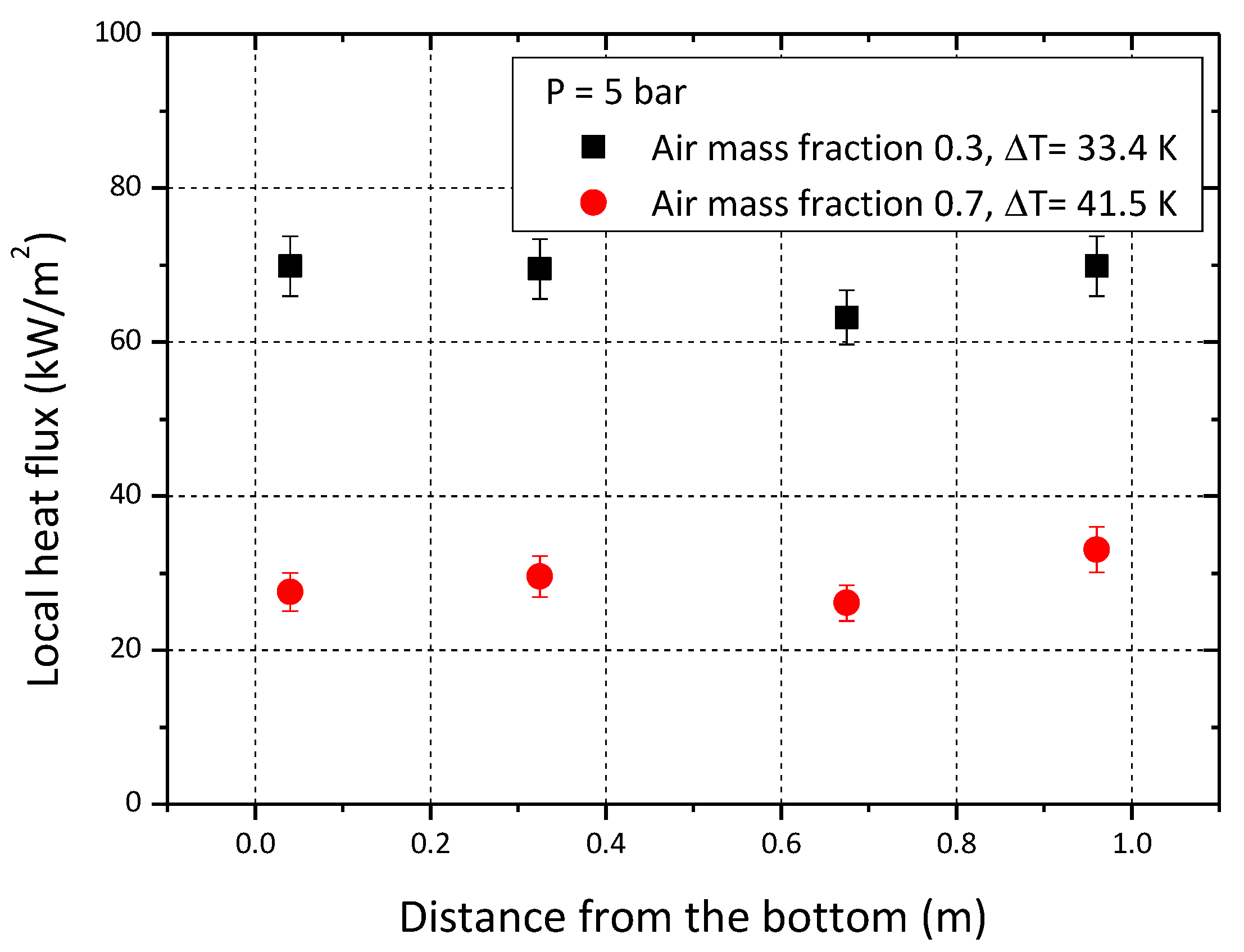
The axial distribution of local heat flux is depicted in Figure 10. The local heat flux along the base tube varied little with an increasing the distance from the top. This is because, in the presence of a noncondensable gas, the thermal resistance between the condensing wall and the bulk is dominated by the conditions of the gas boundary layer, and the gas concentration was axially kept uniform in this test apparatus.
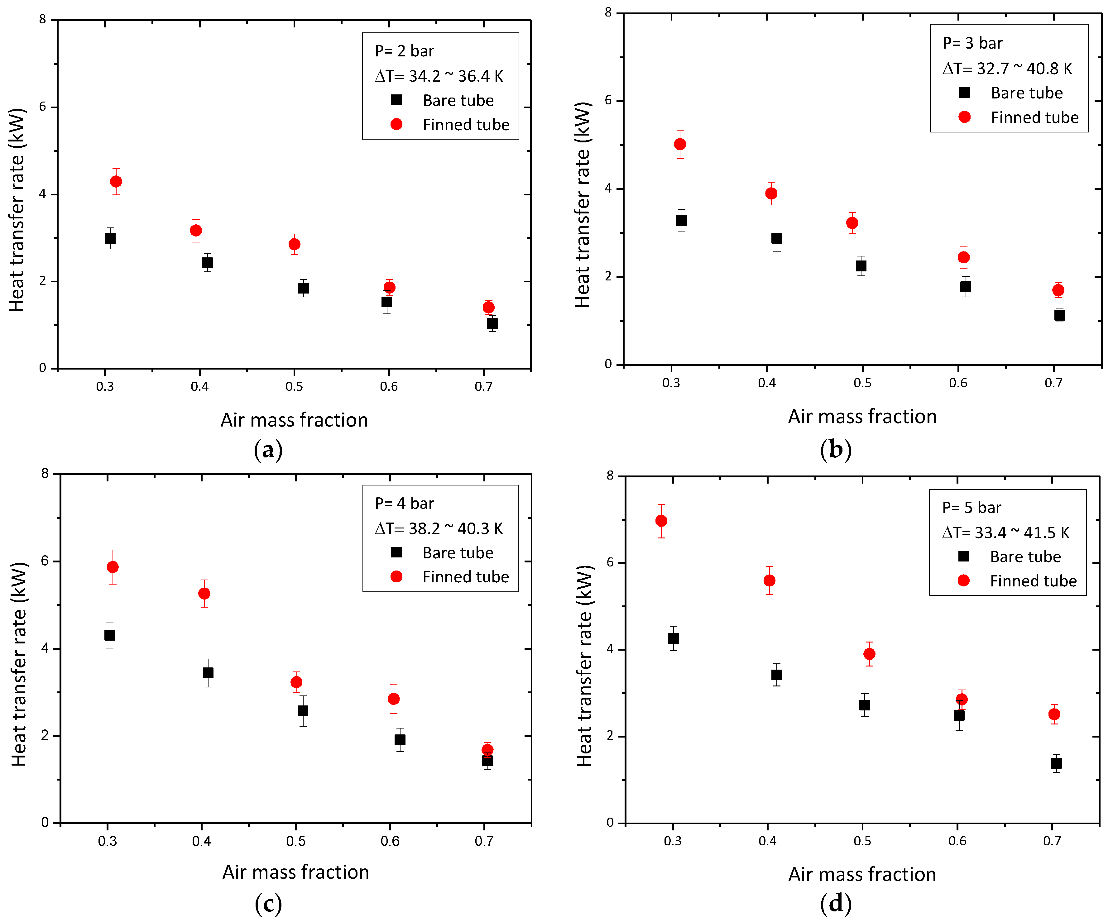
Figure 11 describes the comparison results between the condensation heat transfer rate of the annular finned tube and that of the bare tube in the presence of air under isobaric conditions. Note that both of the test data were measured at almost the same wall temperature at each run; the degree of wall subcooling was kept to nearly 40 K. It was revealed in the previous studies that the heat transfer coefficient increased as the wall subcooling decreased [20]. As the heat flux is influenced by the wall subcooling, the mean wall temperature of the base surface was adjusted close to that of the bare tube for each comparison; the discrepancies were less than 8.4 K. With regard to the experimental results for the annular finned tube, the dependencies of the rate of condensation heat transfer on the pressure and the air concentration were identical to those that have been reported. That is, the heat transfer rate increased with an increase in pressure due to the rise of the steam density. Analytically, the vapor mass flux towards the liquid-vapor interface is proportional to the steam density [22]. In addition, the increase in the air concentration resulted in a substantial degradation of the heat transfer rate because the steam changed into a liquid film at the liquid-vapor interface and the noncondensable gas accumulated near the liquid film. This accumulated layer functions as a barrier to the diffusive flow of steam, as physically explained by Minkowycz and Sparrow [23].
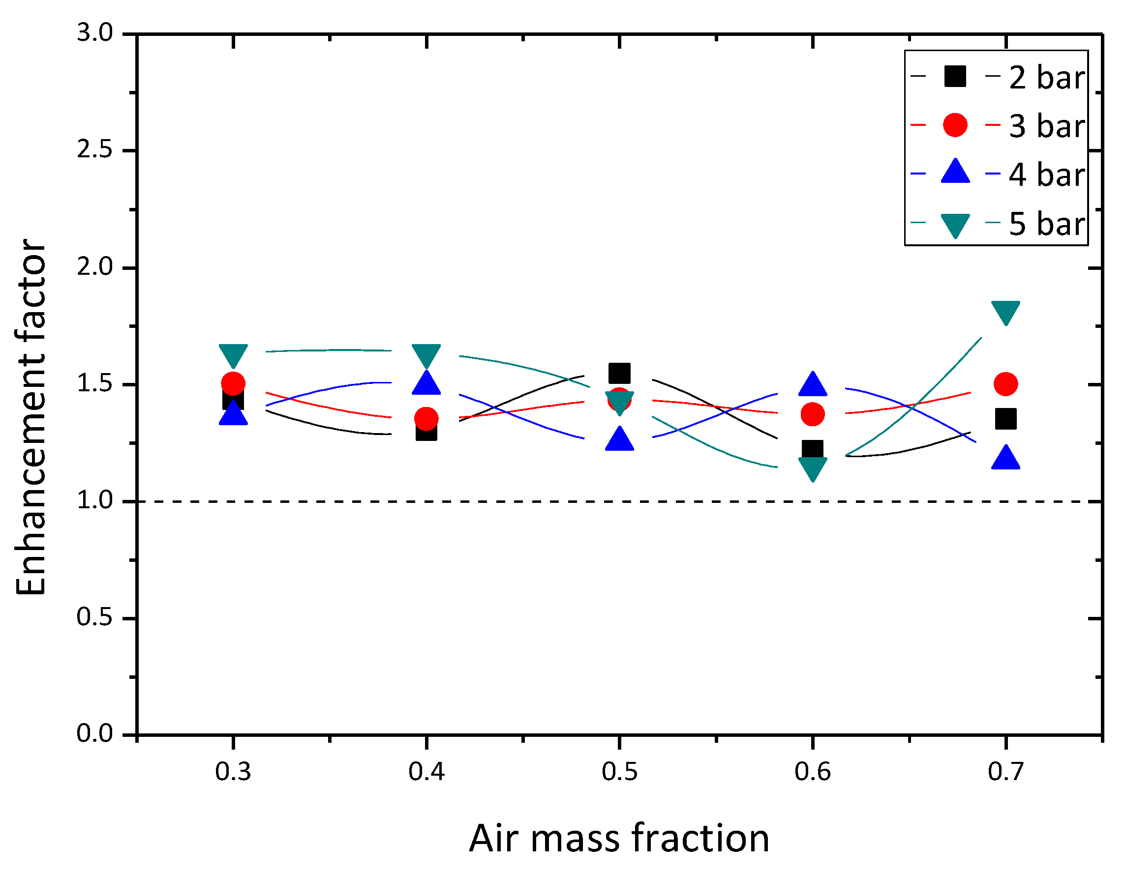
The heat transfer rate of the finned tube was higher than that of the bare tube in various pressure conditions, as depicted in Figure 11, because the presence of the annular fins increased the total surface area for heat transfer on the condenser tube. For a quantitative comparison, the enhancement factor (EF) for the finned tube was defined as:
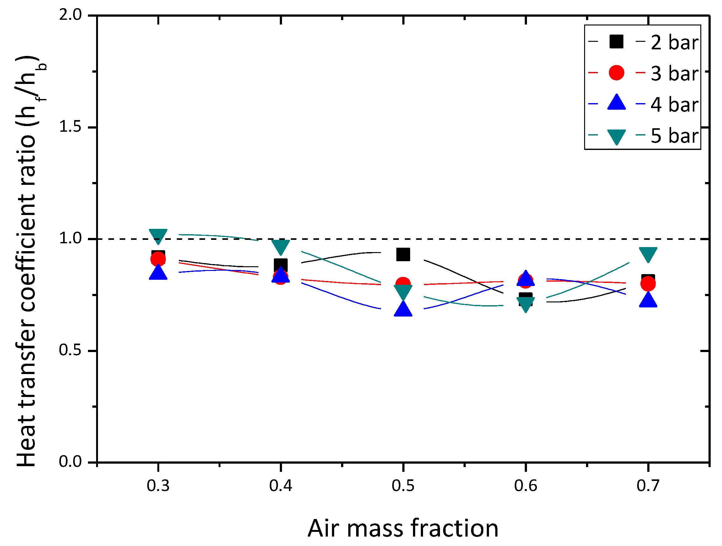
where , , , , , and represent heat transfer coefficients of the finned tube and the bare tube, and the total surface area of both tubes, and the wall subcooling of both tubes, respectively. The wall subcooling of thee finned tube was obtained from the difference between the bulk temperature and base tube temperature of the finned tube. Figure 12 presents the heat transfer enhancement factor over the air mass fraction at each pressure. The enhancement factor distributed between 1.15 and 1.82, and it did not have a clear dependency on the pressure or the air mass fraction. The average enhancement factor was 1.42, which was lower than the ratio of the effective heat transfer (), 1.84. This indicates that, even though the total rate of condensation heat transfer was enhanced by the annular fins, the condensation heat transfer coefficient of the annular finned tube was reduced, as shown in Figure 13. The average ratio of condensation heat transfer coefficient was 0.83.
This happens for two reasons. The first one is the disturbance of the axial flow of the vapor-gas mixture by the annular fin. As discussed in Section 2.1, the annular disk allows for the radial diffusion of steam, while it interrupts the parallel flow of the air-steam mixture along the condensing surface. In the presence of a strong bulk motion of the gaseous mixture parallel to the wall, the buildup of a noncondensable gas at the interface is less accentuated as it sweeps away the gases. Moreover, the parallel flow may promote the turbulence in the vapor-gas boundary layer, which in turn augments the heat and mass transfer by steam condensation. Since the annular disk blocked the parallel motion of the air-steam mixture along the base tube, the mean heat flux was reduced a little by an adoption of the annular finned tube. Consequently, it decreases the condensation heat transfer coefficient. The other reason lies in the presence of a thick condensate film that is retained on the upper surface of the fin, which is visually observed in Figure 8. Since the stored liquid film on the disk increases the thermal resistance for steam condensation, the rate of heat transfer locally degrades.
The above experimental results revealed that the extended surfaces by annular fins enhanced the rate of the condensation heat transfer of the air-steam mixture under natural convection conditions, even though the condensation heat transfer coefficient of the annular finned tube was reduced slightly. This demonstrates that it is a viable approach to employ the annular finned tube for the PCCS when the desired requirement for heat removal capacity cannot be fulfilled with bare condenser tubes that are arranged in the limited space of the containment building.
3.2. Applicability to a Bundle Layout
The ultimate goal of this investigation was associated with the enhancement of the heat removal capacity for the PCCS. From the condensation tests herein using a ‘single’ annular finned tube, the enhanced performance of the condenser tube was experimentally proved. With regard to the fin configuration for the PCCS, it is worth noting the experimental investigation of Tong et al. [16]. They employed longitudinal fins to extend the surface area of a vertical condenser tube, and reported that the heat transfer rate was little affected with an increase in the heat transfer area. Conversely, the longitudinal finned tube weakened the condensation heat transfer process rather than enhancing it when the air mass fraction was lower than 75%. Even though the performance of the longitudinal finned tube can be changed depending on the fin height, thickness, spacing, and so on, the research by Tong et al. suggests that the increase of the surface area by longitudinal fins do not always guarantee the enhanced heat removal capacity for the condenser tube.
Another essential consideration for the applicability of finned tubes to the PCCS is that the heat exchanger assemblies are composed of multiple condenser tubes, and each of them is supposed to suffer from the bundle effect. The existence of a number of fins in the tube bundles results in difficulties in maintenance and repair of the heat exchanger assemblies. Moreover, these fins are expected to accentuate the shadowing effect of tube bundles. In particular, when the longitudinal fins are applied, the condenser tubes at the edges will form a kind of blanket to restrict the influx of steam to the interior tubes, thereby substantially degrading the heat transfer performances of overall PCCS.
In these aspects, the annular fins appear to be a more practical option for the PCCS. Its adoption must be determined on the basis of the investigated advantages and disadvantages in condensation heat transfer, and then a design optimization of the fin arrangement is also needed. In the case of an annular finned tube, the accumulated liquid film on the disk may locally deteriorate the rate of steam condensation as mentioned in Section 3.1. Thus, it would be very helpful to introduce a fin design that facilitates the drainage of the stored condensate on the disk. One example is an annular fin with a reduced cross-sectional area from root to tip. The upper plane of the annular disk with a tilting angle will inhibit the thick liquid film from retaining on heat transfer surfaces by providing effective condensate drainage at the fin tip. Another option includes the helically mounted fin along the base tube. The inclination of the fin may help the continuous drainage of the condensate. Thereafter, by finding the optimum fin height, thickness, and spacing in a bundle layout through numerical studies, one can achieve a maximized heat removal capacity for the PCCS; this remains as future work.
4. Conclusions
The enhancement of the condensation heat transfer of the air-steam mixture on a vertical condenser tube by the annular fins was investigated experimentally. Under natural convection conditions, the total rate of heat transfer was measured in the pressure range between 2 and 5 bar, and the air mass fraction from 0.3 to 0.7, and compared with that of the bare tube. Conclusions from this study are as follows:
- (a)
- The visualization results showed that the inflow of the condensate from an upper fin resulted in the periodic flooding of the liquid film on lower fins, and a thick film was retained on the upper surfaces of the annular disk due to the surface tension.
- (b)
- It was experimentally demonstrated that the total rate of condensation heat transfer was enhanced by the annular fins; the average enhancement factor was 1.54, which was obtained when the heat transfer area was increased by 84%. The average heat flux was degraded due to the disturbance of the parallel flow of the vapor-gas mixture to a condensing surface by the annular fin, and the large thermal resistance formed by the stored thick liquid film on the disk. Consequently, the condensation heat transfer coefficient of the annular finned tube was slightly lower than that of the bare tube.
- (c)
- The annular fin is thought to be a more practical option than the longitudinal fin for the PCCS since it can permit the influx of steam to the interior tubes when it is arranged in a bundle layout. A fin design to facilitate the drainage of the stored condensate on the disk will enhance the efficiency of the annular finned tube.
As a further study, an experimental or numerical investigation to determine the optimum fin height, thickness, and spacing of the annular fin is required in order to achieve a maximized heat removal capacity. In addition, an experimental demonstration of the bundle effect for the finned tube is essential for the application to the prototypical PCCS.
Acknowledgments
This research was supported by Basic Science Research Program through the National Research Foundation of Korea (NRF) funded by the Ministry of Education (No. NRF-2010-0020077) and the Korea Institute of Energy Technology Evaluation and Planning (KETEP) and the Ministry of Trade, Industry & Energy (MOTIE) of the Republic of Korea (No. 20163010150010).
Author Contributions
Yeong-Jun Jang, Dong-Jae Choi, Sin Kim, Myung-Taek Hyun and Yeon-Gun Lee conceived and designed the experiments; Yeong-Jun Jang and Dong-Jae Choi performed the experiments; Sin Kim and Myung-Taek Hyun analyzed the data; Yeong-Jun Jang wrote the paper, with edits from Yeon-Gun Lee.
Conflicts of Interest
The authors declare no conflict of interest.
References
- Song, J.H.; Kim, T.W. Severe accident issues raised by the Fukushima accident and improvements suggested. Nucl. Eng. Technol. 2014, 46, 207–216. [Google Scholar] [CrossRef]
- Uchida, H.; Oyama, A.; Togo, Y. Evaluation of post-incident cooling systems of light-water power reactors. In Proceedings of the Third International Conference on the Peaceful Uses of Atomic Energy, Geneva, Switzerland, 31 August–9 September 1964. [Google Scholar]
- Tagami, T. Interim Report on Safety Assessment and Facilities Establishment Project for June 1965, No. 1; Japanese Atomic Energy Agency: Funaishikawa, Japan, 1965; unpublished results. [Google Scholar]
- Dehbi, A. The Effects of Noncondensable Gases on Steam Condensation under Turbulent Natural Convection Conditions. Ph.D. Thesis, MIT, Cambridge, MA, USA, 1991. [Google Scholar]
- Liu, H. An Experimental Investigation of a Passive Cooling Unit for Nuclear Plant Containment. Ph.D. Thesis, MIT, Cambridge, MA, USA, 1993. [Google Scholar]
- Kawakubo, M.; Aritomi, M.; Kikura, H.; Komeno, T. An experimental study on the cooling characteristics of passive containment cooling systems. J. Nucl. Sci. Technol. 2009, 46, 339–345. [Google Scholar] [CrossRef]
- Dehbi, A. A generalized correlation for steam condensation rates in the presence of air under turbulent free convection. Int. J. Heat Mass Transf. 2015, 86, 1–15. [Google Scholar] [CrossRef]
- Jeon, B.G. An Experimental and Analytical Study of Externally Condensing Heat Exchanger for PCCS with an Air Holdup Tank. Ph.D. Thesis, KAIST, Daejeon, Korea, 2015. [Google Scholar]
- Su, J.; Sun, Z.; Fan, G.; Ding, M. Experimental study of the effect of non-condensable gases on steam condensation over a vertical tube external surface. Nucl. Eng. Des. 2013, 262, 201–208. [Google Scholar] [CrossRef]
- Su, J.; Sun, Z.; Ding, M.; Fan, G. Analysis of experiments for the effect of noncondensable gases on steam condensation over a vertical tube external surface under low wall subcooling. Nucl. Eng. Des. 2014, 278, 644–650. [Google Scholar] [CrossRef]
- Su, J.; Sun, Z.; Zhang, D. Numerical analysis of steam condensation over a vertical surface in presence of air. Ann. Nucl. Energ. 2014, 72, 268–276. [Google Scholar] [CrossRef]
- Porcheron, E.; Lemaitre, P.; Nuboer, A.; Rochas, V.; Vendel, J. Experimental investigation in the TOSQAN facility of heat and mass transfers in a spray for containment application. Nucl. Eng. Des. 2007, 237, 1862–1871. [Google Scholar] [CrossRef]
- Malet, J.; Degrees du Low, O.; Gelain, T. Water evaporation over sump surface in nuclear containment studies: CFD and LP codes validation on TOSQAN tests. Nucl. Eng. Des. 2013, 263, 395–405. [Google Scholar] [CrossRef]
- Tong, P.; Fan, G.; Sun, Z.; Ding, M. Experimental study of steam-air condensation over a vertically longitudinal finned tube. Int. J. Heat Mass Transf. 2015, 89, 1230–1238. [Google Scholar] [CrossRef]
- Tong, T.; Fan, G.; Sun, Z.; Su, J. An experimental investigation of pure steam and steam-air mixtures condensation outside a vertical pin-fin tube. Exp. Thermal Fluid Sci. 2015, 69, 141–148. [Google Scholar] [CrossRef]
- Furuichi, H.; Tamura, A.; Ishida, N.; Kitou, K. Experimental evaluation of enhanced heat transfer performance of a vertical condensation tube with liquid film scattering rings. In Proceedings of the Tenth Korea-Japan Symposium on Nuclear Thermal Hydraulics and Safety, Kyoto, Japan, 27–30 November 2016. [Google Scholar]
- Mori, Y.; Hijikata, K.; Hirasawa, S.; Nakayama, W. Optimized performance of condensers with outside condensing surface. J. Heat Transf. 1981, 103, 96–102. [Google Scholar] [CrossRef]
- Herranz, L.E.; Munoz-Cobo, J.L.; Palomo, M.J. Modeling condensation heat transfer on a horizontal finned tube in the presence of noncondensable gases. Nucl. Eng. Des. 2000, 201, 273–288. [Google Scholar] [CrossRef]
- Munoz-cobo, J.L.; Pena, J.; Herranz, L.E.; Perez-Navarro, A. Steam condensation on finned tubes, in the presence of noncondensable gases and aerosols: influence of impaction, diffusiophoresis and settling on aerosol deposition. Nucl. Eng. Des. 2005, 235, 1225–1237. [Google Scholar] [CrossRef]
- Lee, Y.G.; Jang, Y.J.; Choi, D.J. An experimental study of air-steam condensation on the exterior surface of a vertical tube under natural convection conditions. Int. J. Heat Mass Transf. 2017, 104, 1034–1047. [Google Scholar] [CrossRef]
- Incropera, F.P.; Dewitt, D.P.; Bergman, T.L.; Lavine, A.S. Principles of Heat and Mass Transfer, 7th ed.; John Wiley & Sons: Singapore, 2013. [Google Scholar]
- Collier, J.G.; Thome, J.R. Convective Boiling and Condensation, 3th ed.; Oxford University Press: Oxford, UK, 1994. [Google Scholar]
- Mikowycz, W.J.; Sparrow, E.M. Condensation heat transfer in the presence of noncondensables, interfacial resistance, superheating, variable properties, and diffusion. Int. J. Heat Mass Transf. 1966, 9, 1125–1144. [Google Scholar] [CrossRef]
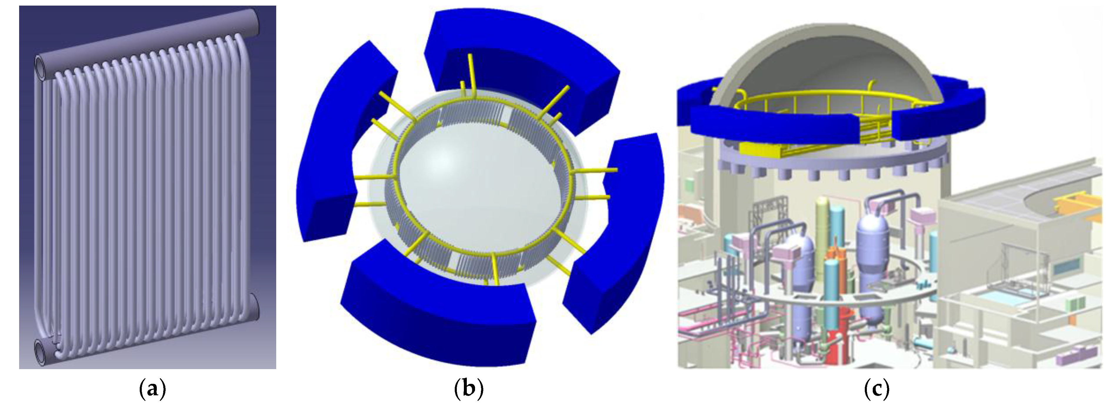
Figure 1.
General concept of the passive containment cooling system (PCCS) with internal condensers. (a) Bundles of vertical condenser tubes; (b) Four trains of tube bundles connected to the passive containment cooling tank; (c) PCCS installed in the containment building.
Figure 1.
General concept of the passive containment cooling system (PCCS) with internal condensers. (a) Bundles of vertical condenser tubes; (b) Four trains of tube bundles connected to the passive containment cooling tank; (c) PCCS installed in the containment building.

Figure 2.
Schematic diagram of the condensation experimental facility.
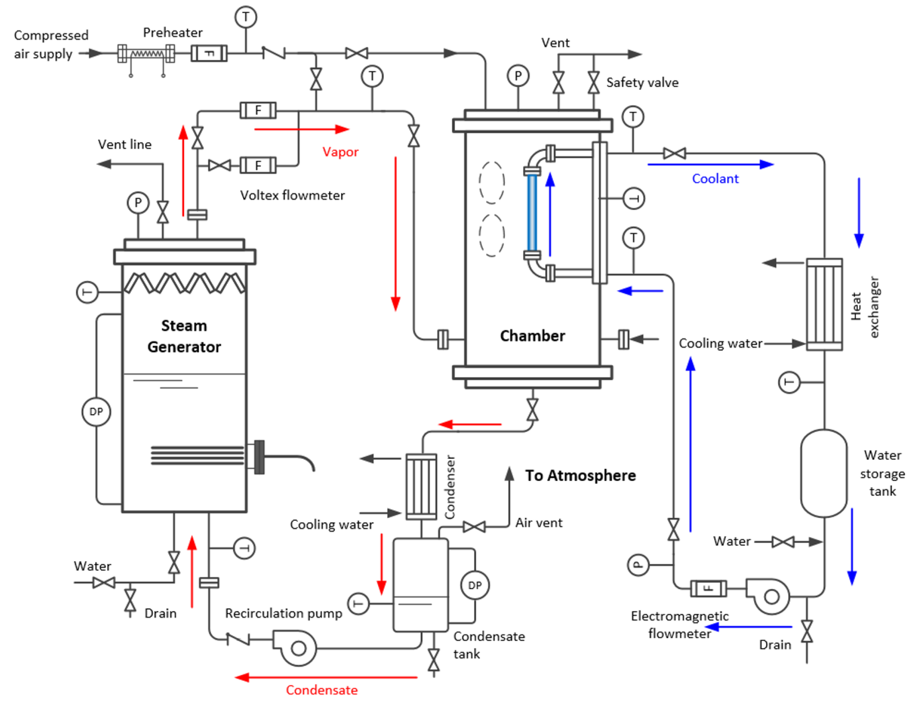
Figure 3.
Annular finned tube used in the study of Liu [5] with unfilled gaps between the base tube and fins.
Figure 3.
Annular finned tube used in the study of Liu [5] with unfilled gaps between the base tube and fins.

Figure 4.
Fabrication process of the annular finned tube in this work.

Figure 5.
Photograph of the fabricated annular finned tube.

Figure 6.
Overall fin efficiency by using the heat transfer coefficient of the preliminary test.

Figure 7.
Locations of the temperature measurement. (a) Thermocouples in the chamber; (b) Thermocouples on the finned tube.
Figure 7.
Locations of the temperature measurement. (a) Thermocouples in the chamber; (b) Thermocouples on the finned tube.

Figure 8.
Visualization results of the liquid condensate on annular fins when air mass fraction is 0.447 at 4 bar. (a–c) Flooding of the condensate captured with a time interval of 10 ms; (d) Thick liquid film retained on the disk between flooding.
Figure 8.
Visualization results of the liquid condensate on annular fins when air mass fraction is 0.447 at 4 bar. (a–c) Flooding of the condensate captured with a time interval of 10 ms; (d) Thick liquid film retained on the disk between flooding.
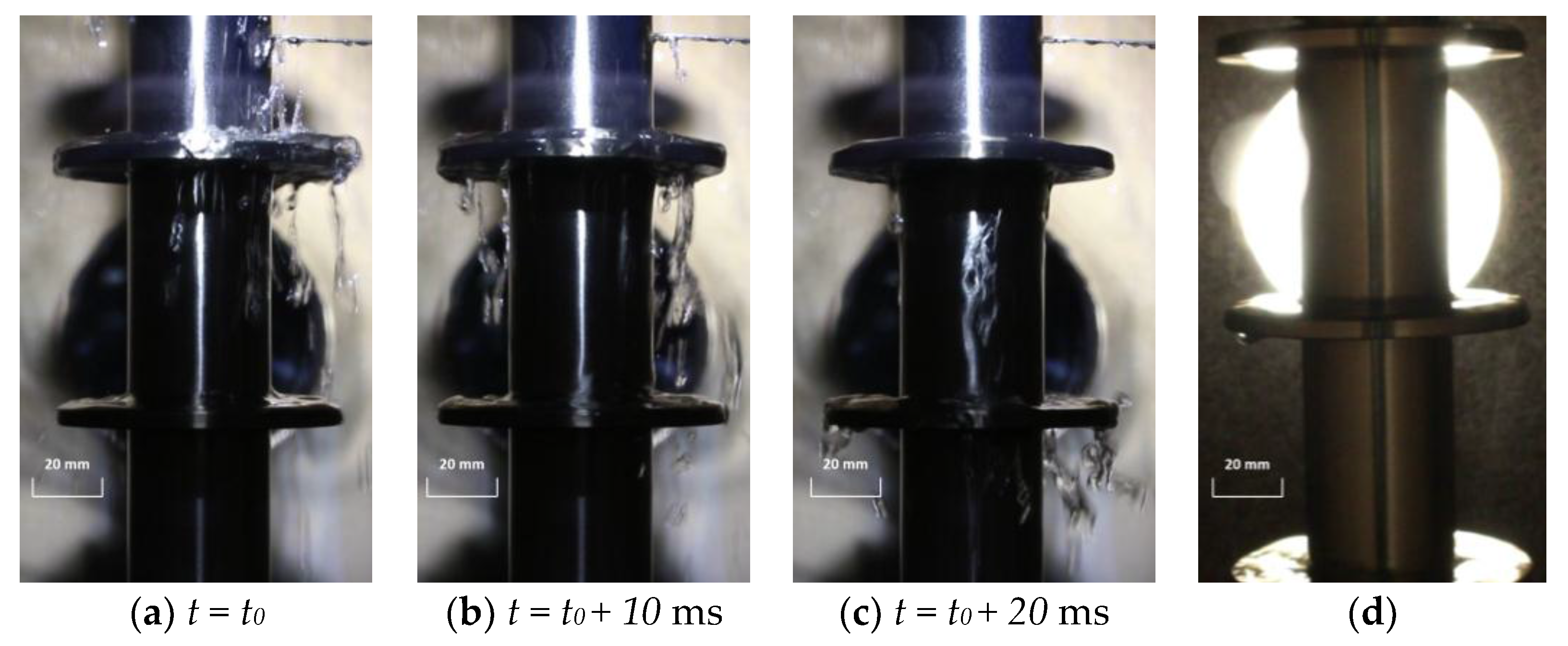
Figure 9.
Typical temperature distribution during the experiment when air mass fraction is 0.6 at 2 bar.
Figure 9.
Typical temperature distribution during the experiment when air mass fraction is 0.6 at 2 bar.

Figure 10.
Local heat flux along the tube height when air mass fraction is 0.3 and 0.7 at 5 bar.

Figure 11.
Comparison of the heat transfer rates between the finned tube and the bare tube at (a) 2 bar, (b) 3 bar, (c) 4 bar, and, (d) 5 bar.
Figure 11.
Comparison of the heat transfer rates between the finned tube and the bare tube at (a) 2 bar, (b) 3 bar, (c) 4 bar, and, (d) 5 bar.

Figure 12.
Enhancement factor along the air mass fraction at 2, 3, 4, and 5 pressure.

Figure 13.
Ratio of the condensation heat transfer coefficient along the air mass fraction at 2, 3, 4, and 5 pressure.
Figure 13.
Ratio of the condensation heat transfer coefficient along the air mass fraction at 2, 3, 4, and 5 pressure.


Table 1.
Test matrix of the finned tube experiment.
| Pressure (bar) | Air Mass Fraction (%) | Wall Subcooling (K) | Coolant Mass Flow Rate (kg/s) |
|---|---|---|---|
| 2 | 30~70 | 34.2~36.4 | 0.13~0.25 |
| 3 | 32.7~40.8 | 0.12~0.26 | |
| 4 | 38.2~40.3 | 0.12~0.35 | |
| 5 | 33.4~41.5 | 0.11~0.31 |
Table 2.
Bias error of measurement instruments.
| Parameter | Measurement Instrument | Bias Error |
|---|---|---|
| Fluid temperature | Thermocouple (K-type) | 0.2 K |
| Wall temperature | Thermocouple (K-type) | 1.1 K |
| Coolant flow rate | Electrical flow meter | 0.1% of span |
| Chamber pressure | Pressure transmitter | 0.075% of span |
© 2017 by the authors. Licensee MDPI, Basel, Switzerland. This article is an open access article distributed under the terms and conditions of the Creative Commons Attribution (CC BY) license (http://creativecommons.org/licenses/by/4.0/).
Share and Cite
MDPI and ACS Style
Jang, Y.-J.; Choi, D.-J.; Kim, S.; Hyun, M.-T.; Lee, Y.-G. Enhancement of Condensation Heat Transfer Rate of the Air-Steam Mixture on a Passive Condenser System Using Annular Fins. Energies 2017, 10, 1777. https://doi.org/10.3390/en10111777
AMA Style
Jang Y-J, Choi D-J, Kim S, Hyun M-T, Lee Y-G. Enhancement of Condensation Heat Transfer Rate of the Air-Steam Mixture on a Passive Condenser System Using Annular Fins. Energies. 2017; 10(11):1777. https://doi.org/10.3390/en10111777
Chicago/Turabian StyleJang, Yeong-Jun, Dong-Jae Choi, Sin Kim, Myung-Taek Hyun, and Yeon-Gun Lee. 2017. "Enhancement of Condensation Heat Transfer Rate of the Air-Steam Mixture on a Passive Condenser System Using Annular Fins" Energies 10, no. 11: 1777. https://doi.org/10.3390/en10111777
Note that from the first issue of 2016, this journal uses article numbers instead of page numbers. See further details here.