Investigation of Permanent Magnet Demagnetization in Synchronous Machines during Multiple Short-Circuit Fault Conditions


The Division of Electricity, Department of Engineering Sciences, Uppsala University, Box 534, 751 21 Uppsala, Sweden
*
Author to whom correspondence should be addressed.
Energies 2017, 10(10), 1638; https://doi.org/10.3390/en10101638
Submission received: 14 September 2017
/
Revised: 29 September 2017
/
Accepted: 13 October 2017
/
Published: 18 October 2017
(This article belongs to the Special Issue Electric Machines and Drives for Renewable Energy Harvesting 2017)
Abstract
:Faults in electrical machines can vary in severity and affect different parts of the machine. This study focuses on various kinds of short-circuits on the terminal side of a generic 20 kW surface mounted permanent magnet synchronous generator and how successive faults affect the performance of the machine. The study was conducted with the commercially available finite element method software COMSOL Multiphysics, and two time-dependent models for demagnetization of permanent magnets were compared, one using only internal models and the other using a proprietary external function. The study is simulation based and the two models were compared to a previously experimentally verified stationary model. Results showed that the power output decreased by more than 30% after five successive faults. In addition, the no-load voltage had become unsymmetrical, which was explained by the uneven demagnetization of the permanent magnets. The permanent magnet with the lowest reduction in average remanence was decreased by 0.8%, while the highest average reduction was 23.8% in another permanent magnet. The internal simulation model was about four times faster than the external model, but slightly overestimated the demagnetization.
1. Introduction
Permanent magnet synchronous machines, PMSMs, are widely used both as industrial motors and as power generators. PMSMs usually have a long expected lifespan and are likely to be exposed to one or several faults during its lifetime. Faults on the rotor side of the generator may be caused by bearing failure, eccentricity, damage of permanent magnets (PMs), asymmetries or mechanical looseness. On the stator, causes of failure can be, for instance, asymmetries, mechanical looseness or winding insulation breakdown. The generator can also be subject to short-circuit events, either originating from internal faults, within the machine, or external faults. In cases when a PMSM is connected to an inverter, faults in switches and sensors may also occur.
There are several observer methods for detecting and predicting faults. The spectrum of the current can be analyzed to determine abnormal frequency components due to, for example, air gap eccentricity [1,2] or partial demagnetization [3,4,5,6,7,8]. This method can be used on machines in production environments for continuous monitoring. A torque-ripple based detection method for demagnetization is suggested in [9]. It has been suggested to analyse pulse width modulation ripple to detect short-circuit faults [10]. Another approach to detect short-circuits is through thermal analysis [11,12].
Eddy current losses have been studied in electrical machines with two-dimensional as well as more accurate three-dimensional simulations [13,14,15]. For some applications, especially in high-speed machines, they could become a problem [16]. In [17], it is concluded that hysteresis loss in permanent magnets do not play any significant role in electrical machines.
While designing a permanent magnet machine, some common faults should be considered. Faults in electrical machines is a common research topic, and there are several studies on demagnetization during different kinds of overload conditions [7,18,19]. However, it is very hard to recognize all possible faults, not only from a technical but also from an economical point of view. If the severity of a fault is so high that the machine needs to be replaced, it is hard economically to justify an analysis of that fault case in detail. While much work has been published on single fault conditions, no previous study has, to our knowledge, been presented on the permanent magnet behavior during multiple short-circuit events. If a PMSM is subject to a short-circuit, only slightly damaging the magnets and nothing else, it might be kept in operation. Since a variable speed synchronous generator is allowed to vary in voltage and is connected to a frequency converter, a decrease in voltage is acceptable. A small decrease in voltage level can be compensated by increasing the current to maintain the intended power level, as long as the current density is kept at a reasonable size. Multiple short-circuit events can occur during several years of operation. The first fault might not make notable damage to the magnets, but it might make the machine more exposed to the next occurring fault. In this study, demagnetization of permanent magnets is investigated during five successive faults.
Previous work on demagnetization within this project includes a study on single short-circuit events on a 12 kW generator using a stationary model [20] as well as experimental verification of the stationary demagnetization model [21]. Furthermore, a study has been made on working point ripple in permanent magnets when the generator is connected to an external electrical circuit [22]. Important previous work on demagnetization include work by Ruoho [19,23,24,25].
2. Study
The main purpose of this paper is to investigate the transient behavior of surface mounted uniformly magnetized Nd-Fe-B permanent magnets in a synchronous generator during several successive fault conditions. This simulation based study has been performed with the commercially available finite element method, FEM, software COMSOL Multiphysics (COMSOL Multiphysics is a registered trademark of COMSOL AB). All simulations were performed in 2D. Any 3D effects such as axial leakage flux and coil end impedances were neglected, e.g., the internal impedance of the generator would be slightly too low since the total length of the winding is underestimated due to the neglected coil ends. This will have a small impact on the results at normal operation since the internal resistance normally is much lower than the resistance of the load. However, this simplification will give a slightly too high short circuit current. All faults are on the terminal side of the generator, i.e., no interwinding short-circuits are considered. Throughout this paper, the three phases of the generator are denoted A, B and C.
Another aim of this paper is to compare two different methods for simulation of demagnetization. The first method uses only built-in models/modules of the FEM software; the second approach takes advantage of a proprietary external function (see Section 4.1).
Eddy current losses could develop in permanent magnets in electrical machines but is a larger problem in machines operating at higher frequency, as eddy current losses increases quadratically with the frequency. The temperature in the magnets is here held constant and set at 60 C and the elevated operational temperature could partly be a result from eddy current losses. However, eddy current losses is not included in this study i.e., a possible small increase in eddy current losses during the short circuit events is not considered here.
3. Machine Modeling
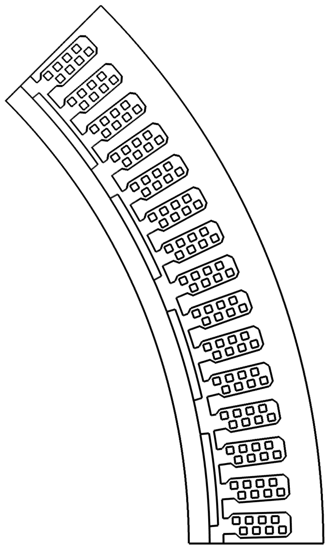
The machine studied in this paper is a modification of the 12 kW generator in [20,26,27], which was designed as a prototype generator for a variable speed wind turbine. For the sake of this study, the air gap has been decreased from 10 to 3 mm and the height of the permanent magnets was decreased from 14 to 5 mm. By making these modifications, the power increased to 20 kW. The main properties of the generator are presented in Table 1 and a figure of the modeled part of the generator is shown in Figure 1, which represents the smallest symmettrical part of the geometry. The properties of the permanent magnets used here; the remanence, , the coercivity, the intrinsic coercivity, and the recoil permeability, , are shown in Table 2. The operational temperature was set at 60 C to make the permanent magnets more susceptible to demagnetization. The magnets are not segmented.
3.1. Electrical Circuit
A schematic of the electrical circuit is shown in Figure 2. The generator output was passively rectified by a diode bridge. The capacitor, , had a capacitance of 0.02 F and the resistance of the load, , was 8 . The resistors , and model the switches used in the short-circuit events. By default, these resistors have a high resistance, 1 M, but, at the time of the short-circuit, the relevant resistor’s resistance was decreased to 0 , creating a short-circuit between the nodes.
The rectifying bridge in the DC circuit needed to be somewhat modified to get the FEM model to converge. The diodes were replaced with voltage-controlled current sources, VCCS, and snubber resistances. The VCCS were controlled by the diode law
where is the diode current, is the voltage across the diode, is the reverse bias saturation current, n is the ideality factor (1.25 was used in this case), and is the thermal voltage. The thermal voltage is defined in
where k is the Boltzmann constant, T is the absolute temperature, and q is the magnitude of the charge of an electron. However, the voltage over the diode (or VCCS in this case) was measured over the snubber resistance since measuring over the VCCS would result in a circular argument in the FEM model. A resistance of 10 k was chosen for the snubber resistance, , to minimize the leakage current.
3.2. Transient Analysis
Two different types of faults are tested in this study and are executed in a series of a total of five faults. The first four cases are phase-phase short-circuits, more specifically: B-C, A-B, B-C again, and then A-B-C. The last fault is a short-circuit over the capacitor on the DC side of the circuit. An assumption made during the short-circuits is that there is an unlimited amount of driving torque available, i.e., a constant rotational frequency is maintained, reducing the complexity of the model. The duration of each short-circuit was two electrical periods. The model was given time to restore a steady state of operation after each fault. The capacitor voltage would drop during the short-circuit and needed to be restored for accurate results in the following fault simulations. All short-circuits were initiated at a certain rotor position and evaluated for four adjacent magnets, since the demagnetization risk is dependent on the relative position of the rotor and the stator. The choice to use the same rotor position for all faults makes the results more comparable and should represent a worst-case scenario for the most affected magnet. For comparison with the successive short-circuit events, all short-circuit events were also individually tested on a healthy machine.
Partially demagnetizing the permanent magnets will lower the induced voltage of the machine. Depending on the circumstances, one can either increase the current to maintain the same output power, replace the permanent magnets or accept the lower output power. In this study, no action was taken, and the new lower output power was accepted.
4. Demagnetization Modeling
4.1. Simulation Models
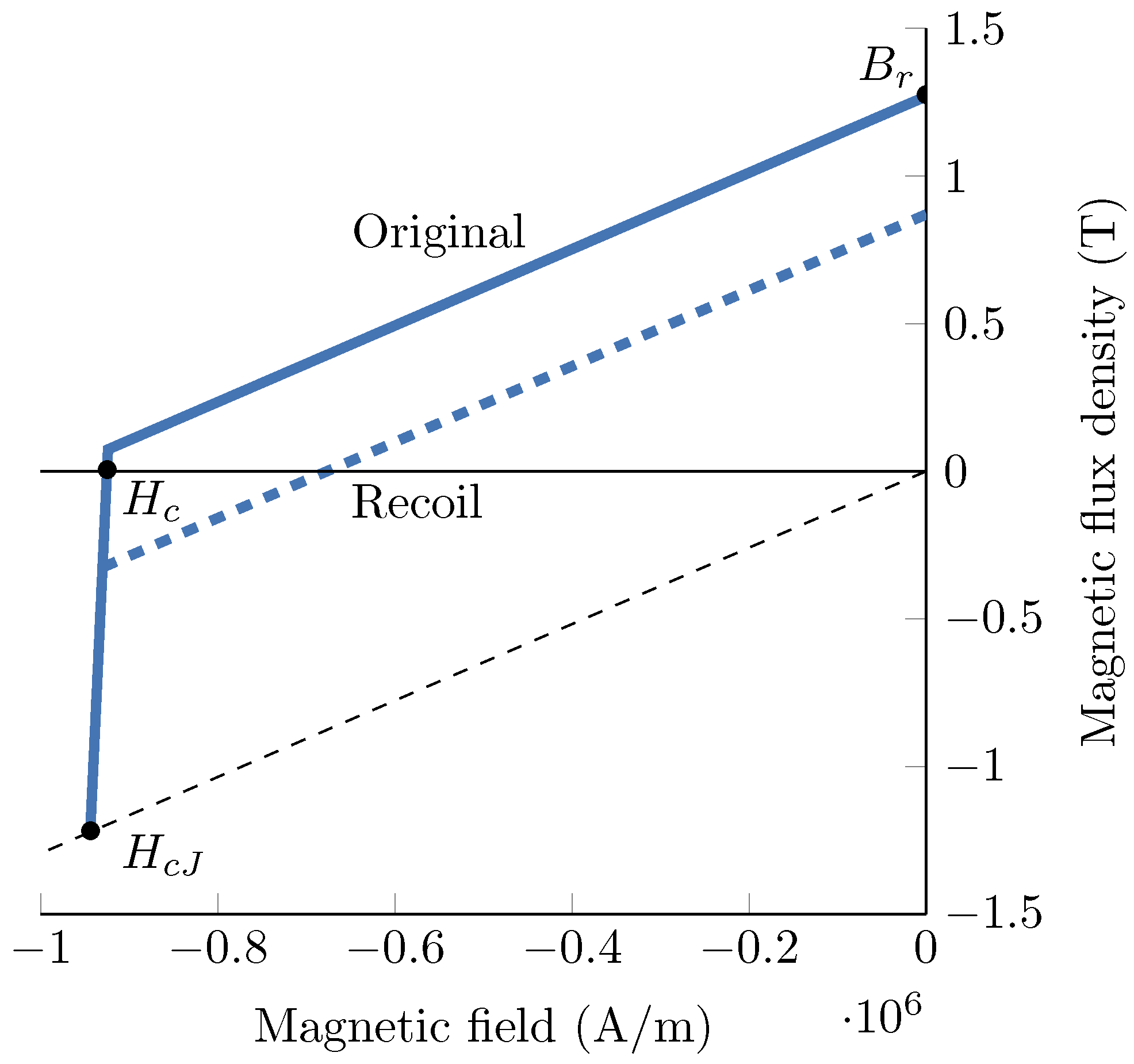
A B-H-curve for the magnets used here is shown in Figure 3. The demagnetization modeling in this study was based on an ideal B-H-curve, i.e., the B-H-curve in the second quadrant was modeled as two straight lines. Hamidizadeh et al. have shown in [28] that there is little influence on the results when using a sharp knee compared to an exponential model [24], at least for permanent magnets with very sharp knees.
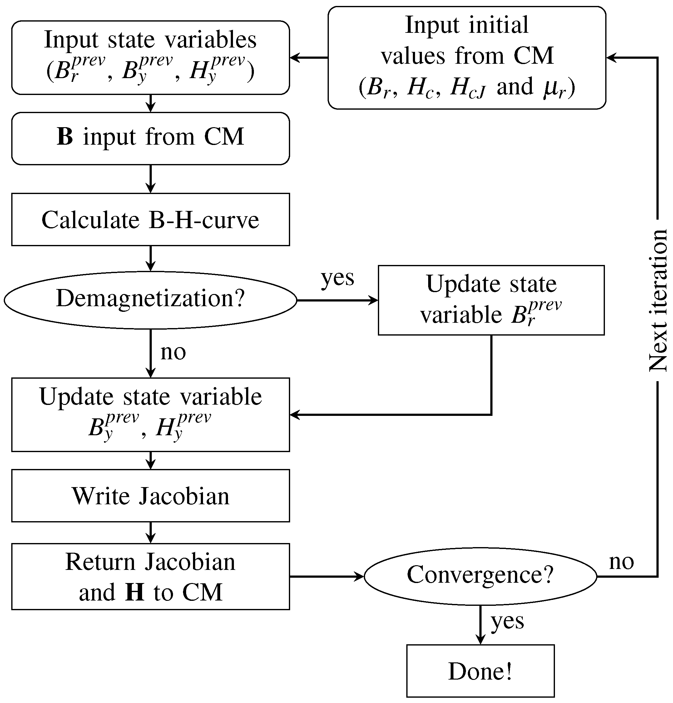
The permanent magnets were modeled using two different models that used the same basic principle; one uses only an internal function, and the other uses an external C-function written by the authors. During each solver iteration, the magnetic flux density is checked to see if it is below the knee of the B-H-curve; if so, a new remanence was calculated using a straight line approximation, and a new B-H-curve was generated (see the recoil line in Figure 3). The main difference between the models is that the internal model checks the magnetic flux density from the previous time step while the external function model checks the magnetic flux density in the current time step. Checking demagnetization in the current time step should be more time consuming since it will affect the calculation of the current step in each iteration. When checking for demagnetization, only the magnetic flux density parallel to the magnetization direction (here denoted y) was considered, since this has proven to work well for multi-pole machines, and it is hard to quantify the angular dependence [19,29]. Another difference between the models is that the Jacobian (the system matrix) had to be manually defined in the external function. A flowchart for the simulation model with the external function can be seen in Figure 4.
4.2. Comparison to Verified Model
The two models were verified against a stationary model based on the same principle, which, with good agreement, has been compared to experiments [20,21]. A three-legged iron core where the middle leg had an air gap, one leg had a permanent magnet and one leg had a coil of 100 turns was used for the comparison. The two models were exposed to a current pulse while the stationary model was simulated with only the peak value of the current.
The mesh in this model consists of a total of 2492 elements of which 400 are quadrilateral inside the permanent magnet; the rest were triangular. To further evaluate the computational time between the two models, the mesh inside the permanent magnet was refined to about twice the amount of elements, 855, which increased the total number of mesh elements to 3405.
5. Results
Results from the comparison with the stationary model are presented in Table 3. The second column in the table shows the average remanence from the stationary model. Int diff and Ext diff shows the difference in average remanence between the internal/external models compared to the stationary model, both in Tesla and in percent. Int speed refers to how many times faster the internal model was compared to the external. The comparison between the two models and their stationary counterpart showed that the internal model is faster than the external model, but tends to slightly overestimate the demagnetization.
The no-load voltage, , for the healthy machine was 189.4 V, as shown in Figure 5a and Table 1. The no-load voltage for the external model after each short-circuit event was: 174.8, 156.3, 156.3, 156, and 156 V, respectively. For the internal model, the no-load voltage after all faults was 153.8 V. The no-load voltage for the external model after the subsequent faults is plotted in Figure 5b.
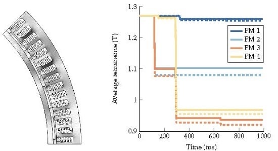
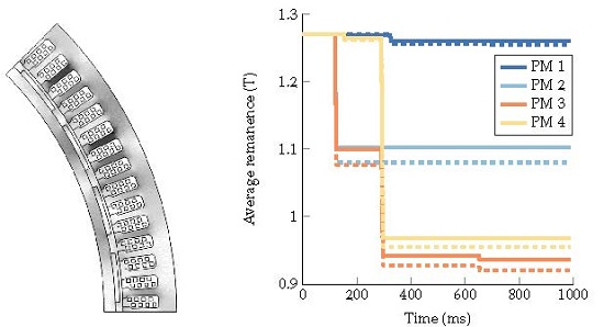
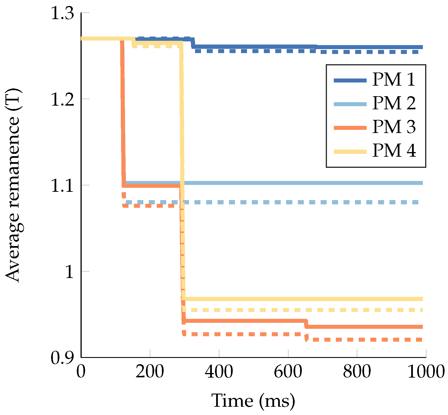
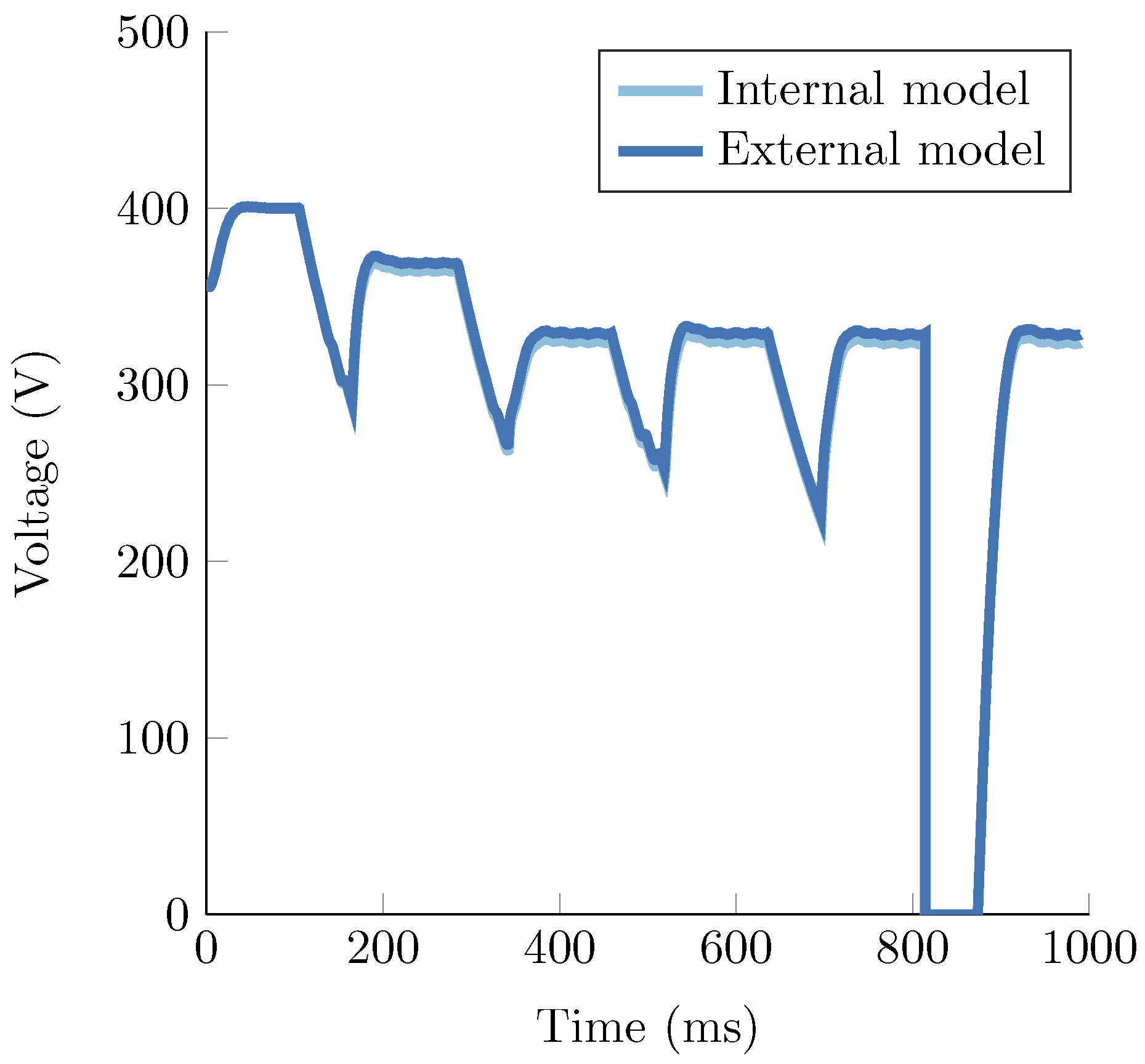
The average remanence in the permanent magnets during all short-circuit events for both models are presented in Figure 6. It can be seen in Figure 6 that the average remanence of PM 1 only slightly decreased (0.8%), which can be compared to PM 3 who suffered from major demagnetization (23.8%). In Figure 7, the voltage over the capacitor is shown as well as how the generator was allowed to reach a new steady state of operation after each fault.
After all fault conditions, the new power output was 13.5 kW and 13.1 kW for the external and internal model, respectively. Remember that no changes were done to any parts of the machine or electrical system between the faults.
To compare the results from the successive faults, Table 4 presents the maximum amplitude of the short-circuit current in each phase for each type of short-circuit occurring on a healthy machine. As can be expected, the A-B-C case has similar results to the DC case. Table 5 presents the no-load voltage and the average remanence for each case occurring on a healthy machine for the external simulation model. Results for the internal model were generally about 3% lower. The no-load voltage on the healthy machine was 189.4 V and the remanence of the magnets was 1.27 T.
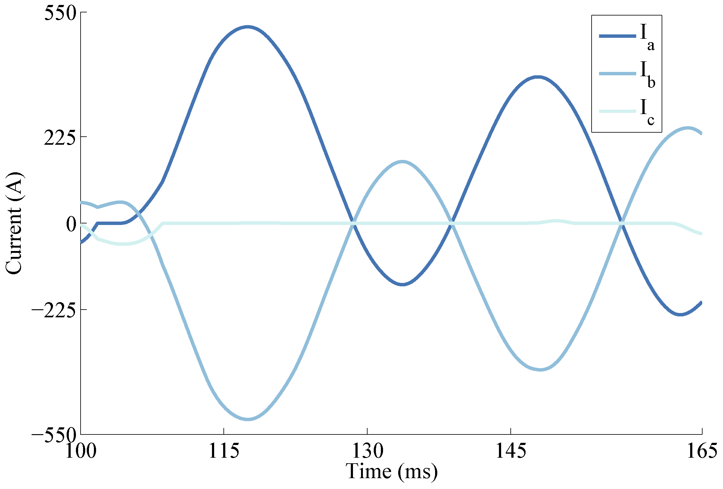
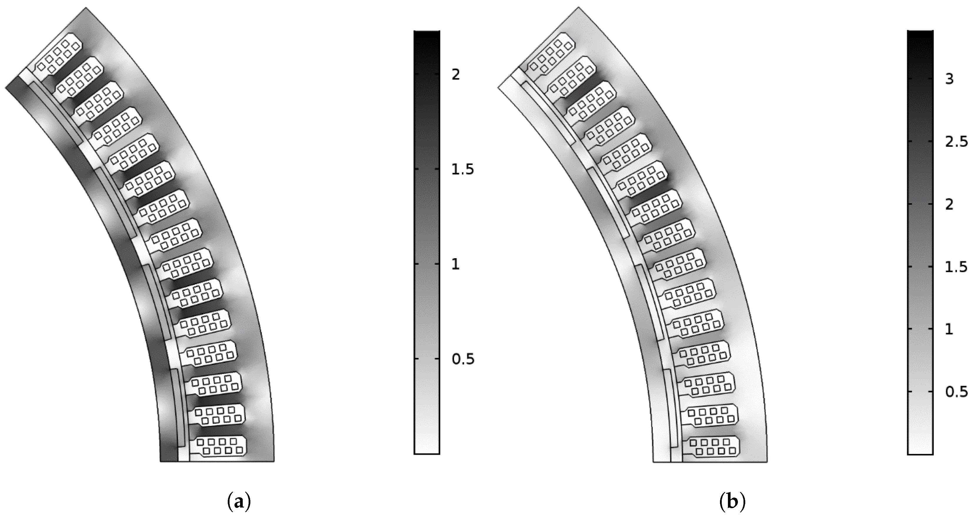
The short-circuit current in each phase for case A-B occurring on a healthy machine is shown in Figure 8. For the same case, the magnetic flux density in the generator after the short-circuit is shown in Figure 9b. The rotor is displaced 0.7 mechnical degrees in the figure. However, this is so small it will not affect how the figure looks. The magnetic flux density in the generator for no load is shown in Figure 9a for comparison.
6. Discussion
After the subsequent faults, the root mean square (RMS) value of the no load voltage dropped less than 20 percent. However, when comparing the no-load voltage in Figure 5a,b, the voltage after the fault conditions are somewhat unsymmetrical where every other period has a higher peak. Analyzing the average in Figure 6, it can also be observed that the permanent magnets are not symmetrically demagnetized either, which explains the unsymmetrical induced voltage. This uneven voltage will also affect the torque and an overtone with a frequency of 1.5 times the electrical frequency was introduced into the torque ripple. An increase in torque could give problems with increased vibrations, especially at lower frequencies when the damping from the generator and shaft dynamics is lower. Therefore, low vibrational frequencies are more easily transferred through the generator and shaft to the turbine [30].
Analyzing Figure 7, one comes to the conclusion that not much has happened during the last three short-circuit events. The capacitor voltage is directly proportional to the current in the load, so the delivered power is hardly decreased during the last three short-circuit events. From the results in Table 5 and the presented no-load voltages after each short-circuit in the results section, one can conclude that it is not only the number of faults that is important. The order in which the faults occur will also determine the principal amount of demagnetization. If, for instance, the A-B-C case would have occured first, the subsequent faults would have little to zero impact on the demagnetization. The significance of the rotor postition when the fault occurs is also apparent from Table 5 as the affect on the four magnets clearly differs. This is especially apparent for the short circuit case B-C, for which PM 2 and PM 3 are most affected, whereas PM 3 and PM 4 are most affected in all other cases.
The effect of a short-circuit on the magnetic flux density in the generator can be seen in Figure 9. The magnetic flux density is much lower in the magnets after the demagnetization and a few of the stator teeth become highly saturated.
Regarding the computational time difference between the internal and the external model, the results can be somewhat misleading. As can be seen in Table 3, the time difference increases significantly in the last two rows. This increase can somewhat be explained by the procedure of the comparison study, and the majority of the time steps were taken at the moment of the demagnetization. Since the comparison study only consists of a short high current pulse (see Section 4.2), this will have a great impact on the results. If the study would have been longer as in the study on the generator, the time difference would probably be closer to four, as in the other cases, since the duration of the demagnetization would be a smaller fraction of the total simulation time. In other words, the external model takes about 3.5 to 4 times longer at low demagnetizing fields but takes longer to converge at high demagnetizing fields. In Table 3, one can also see that the external function has a slightly better accuracy than the internal model compared to the experimentally verified stationary model. Furthermore, the external model is also more versatile and new functionality can easily be added.
If the load had been adjusted between the different short-circuit events, to increase the current and thereby maintain the output power, the short-circuit currents would also have been increased for the later cases, leading to higher demagnetization. Since the load was kept constant, the current was reduced due to the decrease in induced voltage as a result of the demagnetization of the permanent magnets. The unsymmetrical demagnetization could also have had an influence on the magnetic circuit of the machine. A decrease in magnetic flux could have reduced leakage flux in certain parts of the machine where the iron was saturated, or for other reasons alter its path. However, this was not further investigated.
7. Conclusions
This paper has investigated demagnetization of PMs in a PMSM subject to successive short-circuit faults. During its lifetime, a generator could be subject to several short-circuit events and the conclusion found here is that the generator will suffer some initial damage but might after that be less sensitive to short-circuits. This is contrary to what could be expected: that a previous short-circuit event could make the machine more exposed to damage from a coming fault. The main conclusion is therefore that if the machine is designed to survive the most common short-circuit events, it should also be able to survive a series of short-circuit events.
The induced voltage can become unsymmetrical after a short-circuit even at low demagnetization and quite low voltage drop. This can potentially cause problems due to a higher amount of harmonics and increased torque ripple. A higher number of faults does not necessarily equal larger damage to the machine; as seen here, there was only a marginal difference in power output during the three last short-circuits of the subsequent faults. However, an important aspect is also the order in which the faults occur. Furthermore, the external simulation model is more accurate but at about one-fourth of the computational speed compared to the internal model. The external model is still preferred because of its versatility as it is written by the user.
Acknowledgments
This work was supported by the Swedish strategic research programme StandUp for Energy and from the Swedish Research Council (Grant No. 2010-3950).
Author Contributions
Stefan Sjökvist performed most of the work and wrote most of the paper. Sandra Eriksson supervised the work.
Conflicts of Interest
The authors declare no conflict of interest.
References
- Thomson, W.T.; Fenger, M. Current signature analysis to detect induction motor faults. IEEE Ind. Appl. Mag. 2001, 7, 26–34. [Google Scholar] [CrossRef]
- Lopez-Torres, C.; Riba, J.R.; Garcia, A.; Romeral, L. Detection of Eccentricity Faults in Five-Phase Ferrite-PM Assisted Synchronous Reluctance Machines. Appl. Sci. 2017, 7. [Google Scholar] [CrossRef]
- Moosavi, S.; Djerdir, A.; Amirat, Y.A.; Khaburic, D. Demagnetization fault diagnosis in permanent magnet synchronous motors: A review of the state-of-the-art. J. Magn. Magn. Mater. 2015, 391, 203–212. [Google Scholar] [CrossRef]
- Chakraborty, S.; Keller, E.; Ray, A.; Mayer, J. Detection and estimation of demagnetization faults in permanent magnet synchronous motors. Electr. Power Syst. Res. 2013, 96, 225–236. [Google Scholar] [CrossRef]
- Rosero, J.A.; Cusido, J.; Garcia, A.; Ortega, J.A.; Romeral, L. Study on the Permanent Magnet Demagnetization Fault in Permanent Magnet Synchronous Machines. In Proceedings of the IECON 2006—32nd Annual Conference on IEEE Industrial Electronics, Paris, France, 6–10 November 2006; pp. 879–884. [Google Scholar]
- Casadei, D.; Filippetti, F.; Rossi, C.; Stefani, A. Magnets faults characterization for Permanent Magnet Synchronous Motors. In Proceedings of the IEEE International Symposium on Diagnostics for Electric Machines, Power Electronics and Drives, Cargese, France, 31 August–3 September 2009; pp. 1–6. [Google Scholar]
- Ruschetti, C.; Verucchi, C.; Bossio, G.; Angelo, C.D.; García, G. Rotor demagnetization effects on permanent magnet synchronous machines. Energy Convers. Manag. 2013, 74, 1–8. [Google Scholar] [CrossRef]
- Ruiz, J.R.R.; Rosero, J.A.; Espinosa, A.G.; Romeral, L. Detection of Demagnetization Faults in Permanent-Magnet Synchronous Motors Under Nonstationary Conditions. IEEE Trans. Magn. 2009, 45, 2961–2969. [Google Scholar] [CrossRef]
- Zhu, M.; Hu, W.; Kar, N.C. Torque-Ripple-Based Interior Permanent-Magnet Synchronous Machine Rotor Demagnetization Fault Detection and Current Regulation. IEEE Trans. Ind. Appl. 2017, 53, 2795–2804. [Google Scholar] [CrossRef]
- Hu, R.; Wang, J.; Sen, B.; Mills, A.R.; Chong, E.; Sun, Z. PWM Ripple Currents Based Turn Fault Detection for Multiphase Permanent Magnet Machines. IEEE Trans. Ind. Appl. 2017, 53, 2740–2751. [Google Scholar] [CrossRef]
- Singh, G.; Kumar, T.; Naikan, V. Induction motor inter turn fault detection using infrared thermographic analysis. Infrared Phys. Technol. 2016, 77, 277–282. [Google Scholar] [CrossRef]
- Glowacz, A.; Glowacz, Z. Diagnosis of the three-phase induction motor using thermal imaging. Infrared Phys. Technol. 2016, 81. [Google Scholar] [CrossRef]
- Chen, L.; Wang, J.; Nair, S.S. An Analytical Method for Predicting 3-D Eddy Current Loss in Permanent Magnet Machines Based on Generalized Image Theory. IEEE Trans. Magn. 2016, 52, 1–11. [Google Scholar] [CrossRef]
- Li, Q.; Fan, T.; Wen, X.; Ning, P. An Analytical Approach to Magnet Eddy-Current Losses for Interior Permanent-Magnet Synchronous Machines During Flux Weakening. IEEE Trans. Magn. 2015, 51, 1–9. [Google Scholar] [CrossRef]
- Koo, M.; Choi, J.; Jeong, J.; Kim, J.; Park, Y. Comparative analysis of eddy current loss in permanent magnet synchronous generator considering PM shape and skew effect for wind power generation. In Proceedings of the INTERMAG 2015—IEEE International Magnetics Conference, Beijing, China, 11–15 May 2015. [Google Scholar]
- Yang, Z.; Shang, F.; Brown, I.P.; Krishnamurthy, M. Comparative Study of Interior Permanent Magnet, Induction, and Switched Reluctance Motor Drives for EV and HEV Applications. IEEE Trans. Transp. Electr. 2015, 1, 245–254. [Google Scholar] [CrossRef]
- Pyrhönen, J.; Ruoho, S.; Nerg, J.; Paju, M.; Tuominen, S.; Kankaanp, H.; Stern, R.; Boglietti, A.; Uzhegov, N. Hysteresis Losses in Sintered NdFeB Permanent Magnets in Rotating Electrical Machines. IEEE Trans. Ind. Electr. 2015, 62, 857–865. [Google Scholar] [CrossRef]
- McFarland, J.D.; Jahns, T.M. Investigation of the Rotor Demagnetization Characteristics of Interior PM Synchronous Machines During Fault Conditions. IEEE Trans. Ind. Appl. 2014, 50, 2768–2775. [Google Scholar] [CrossRef]
- Ruoho, S.; Arkkio, A. Partial Demagnetization of Permanent Magnets in Electrical Machines Caused by an Inclined Field. IEEE Trans. Magn. 2008, 44, 1773–1778. [Google Scholar] [CrossRef]
- Sjökvist, S.; Eriksson, S. Study of Demagnetization Risk for a 12 kW Direct Driven Permanent Magnet Synchronous Generator for Wind Power. Energy Sci. Eng. 2013, 1, 128–134. [Google Scholar] [CrossRef]
- Sjökvist, S.; Eriksson, S. Experimental Verification of a Simulation Model for Partial Demagnetization of Permanent Magnets. IEEE Trans. Magn. 2014, 50, 1–5. [Google Scholar] [CrossRef]
- Sjökvist, S.; Rossander, M.; Eriksson, S. Permanent Magnet Working Point Ripple in Synchronous Generators. J. Eng. 2017, 1–4. [Google Scholar] [CrossRef]
- Ruoho, S. Modeling Demagnetization of Sintered NdFeB Magnet Material in Time-Discretized Finite Element Analysis. Ph.D. Thesis, Aalto University School of Electrical Engineering, Espoo, Finland, 2011. [Google Scholar]
- Ruoho, S.; Dlala, E.; Arkkio, A. Comparison of demagnetization models for finite-element analysis of permanent-magnet synchronous machines. IEEE Trans. Magn. 2007, 43, 3964–3968. [Google Scholar] [CrossRef]
- Ruoho, S.; Kolehmainen, J.; Ikäheimo, J.; Arkkio, A. Interdependence of demagnetization, loading, and temperature rise in a permanent-magnet synchronous motor. IEEE Trans. Magn. 2010, 46, 949–953. [Google Scholar] [CrossRef]
- Eriksson, S.; Solum, A.; Leijon, M.; Bernhoff, H. Simulations and experiments on a 12 kW direct driven PM synchronous generator for wind power. Renew. Energy 2008, 33, 674–681. [Google Scholar] [CrossRef]
- Eriksson, S.; Bernhoff, H.; Leijon, M. FEM Simulations and Experiments of Different Loading Conditions for a 12 kW Direct Driven PM Synchronous Generator for Wind Power. Int. J. Emerg. Electr. Power Syst. 2009, 10. [Google Scholar] [CrossRef]
- Hamidizadeh, S.; Alatawneh, N.; Chromik, R.R.; Lowther, D.A. Comparison of Different Demagnetization Models of Permanent Magnet in Machines for Electric Vehicle Application. IEEE Trans. Magn. 2016, 52, 1–4. [Google Scholar] [CrossRef]
- Katter, M. Angular dependence of the demagnetization stability of sintered Nd-Fe-B magnets. IEEE Trans. Magn. 2005, 41, 3853–3855. [Google Scholar] [CrossRef]
- Rossander, M.; Goude, A.; Eriksson, S. Mechanical torque ripple from a passive diode rectifier in a 12 kW vertical axis wind turbine. IEEE Trans. Energy Convers. 2017, 32, 164–171. [Google Scholar] [CrossRef]
Figure 1.
The generator geometry used in the study representing the smallest symmetrical part of the geometry. The permanent magnets are denoted Permanent magnet (PM) 1 through 4 from the bottom up.
Figure 1.
The generator geometry used in the study representing the smallest symmetrical part of the geometry. The permanent magnets are denoted Permanent magnet (PM) 1 through 4 from the bottom up.

Figure 2.
A schematic figure of the DC rectification circuit. In the simulations, each diode was substituted with a voltage-controlled current source and a snubber resistance, shown to the right.
Figure 2.
A schematic figure of the DC rectification circuit. In the simulations, each diode was substituted with a voltage-controlled current source and a snubber resistance, shown to the right.
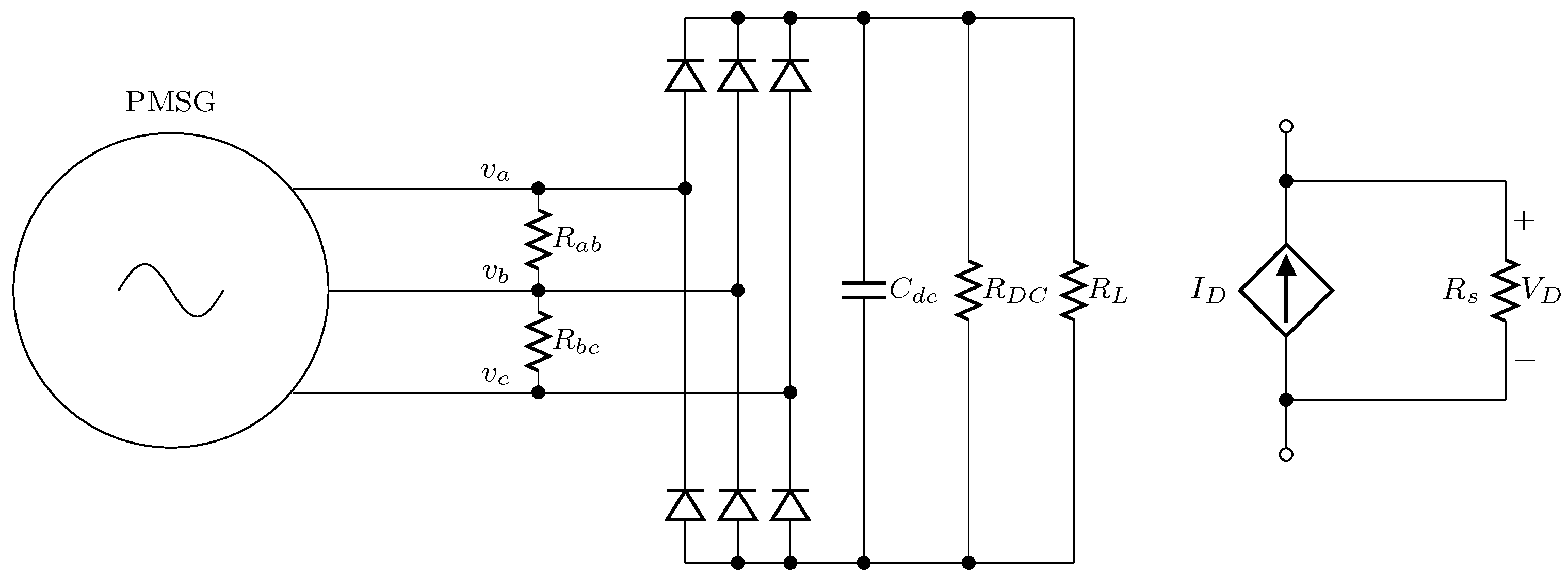
Figure 3.
Ideal B-H-curve for the permanent magnet used in the study with an arbitrary straight recoil line.
Figure 3.
Ideal B-H-curve for the permanent magnet used in the study with an arbitrary straight recoil line.

Figure 4.
Flowchart for the demagnetization simulation model with the external function.

Figure 5.
(a) the no-load voltage of the healthy machine; (b) the no-load voltage after the short-circuits for the external model.
Figure 5.
(a) the no-load voltage of the healthy machine; (b) the no-load voltage after the short-circuits for the external model.
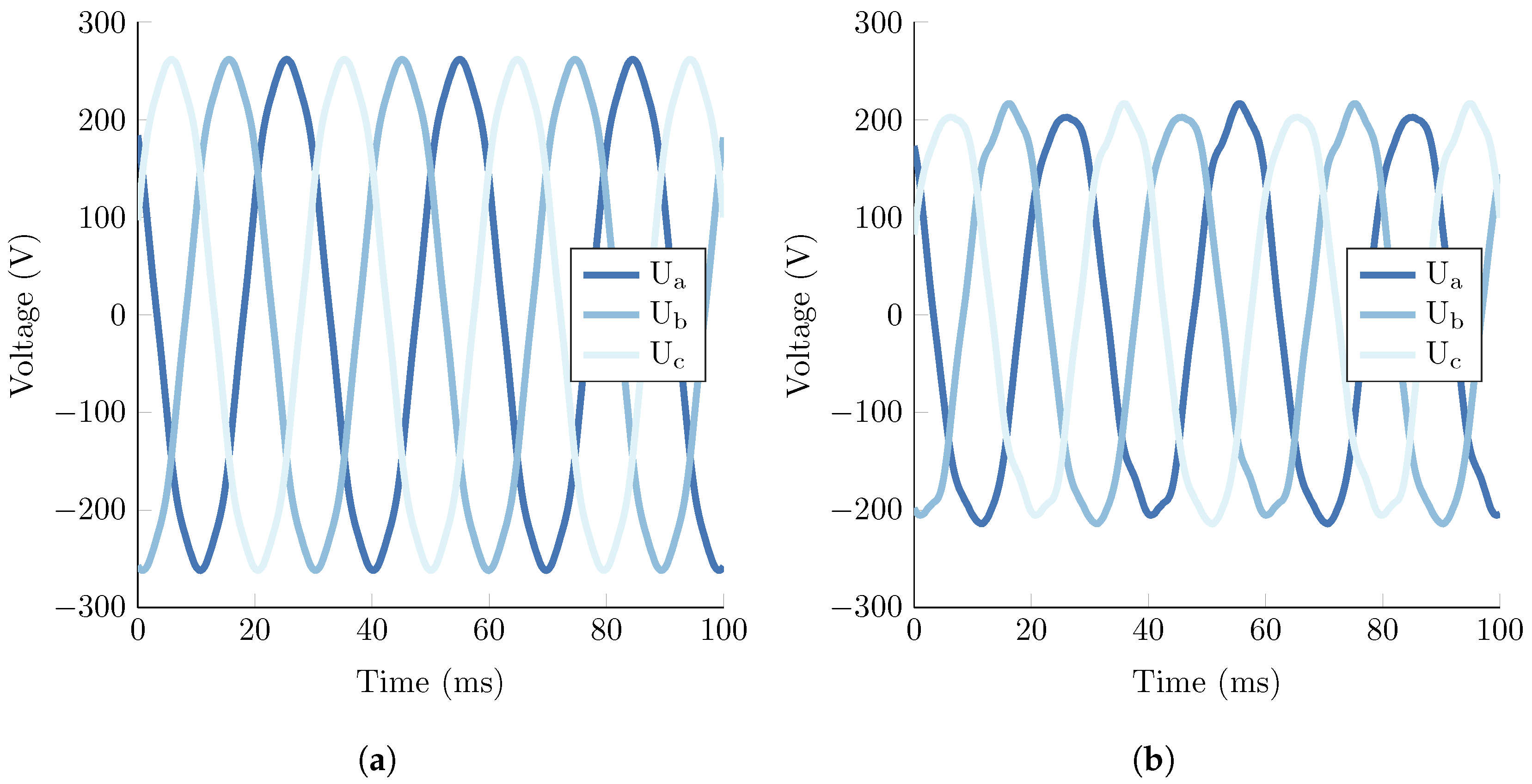
Figure 6.
The average remanence in each magnet during all short-circuit events. The solid and dashed lines are from the external function model and the internal model, respectively.
Figure 6.
The average remanence in each magnet during all short-circuit events. The solid and dashed lines are from the external function model and the internal model, respectively.

Figure 7.
Voltage over the capacitor during all the successive fault events for both models.

Figure 8.
The short-circuit current for the A-B case in all three phases.

Figure 9.
(a) the magnetic flux density at no-load before any fault; (b) the magnetic flux density in the machine after an A-B short-circuit from the external model.
Figure 9.
(a) the magnetic flux density at no-load before any fault; (b) the magnetic flux density in the machine after an A-B short-circuit from the external model.


Table 1.
The main properties of the 20 kW generator used in this study.
| Power | 20 kW |
| Current, DC-load, rms | 50 A |
| Voltage, DC-load, rms | 400 V |
| Phase voltage, no-load, rms | 189.4 V |
| Number of poles | 32 |
| Rotational speed | 127 rpm |
| Electrical frequency | 33.9 Hz |
| Air gap | 3 mm |
| Permanent magnet height | 5 mm |
| Permanent magnet width | 54 mm |
| Machine length | 224 mm |
| Stator radius (inner/outer) | 380/437 mm |
Table 2.
Properties, at 60 C, of the Nd-Fe-B permanent magnets used in the study.
| (T) | (kA/m) | (kA/m) | |
|---|---|---|---|
| 1.27 | −925 | −944 | 1.03 |
Table 3.
Comparison of the two models to a stationary model for an iron core.
| Stat. | Int Diff | Ext Diff | Int Speed | ||||
|---|---|---|---|---|---|---|---|
| I (A) | (T) | (T) | (%) | (T) | (%) | mesh x1 | mesh x2 |
| 0 | 1.270 | 0 | 100 | 0 | 100 | 4.3 | 4.1 |
| 10 | 1.270 | 0 | 100 | 0 | 100 | 3.9 | 3.8 |
| 20 | 1.270 | 0 | 100 | 0 | 100 | 3.3 | 3.3 |
| 30 | 1.270 | 0 | 100 | 0 | 100 | 3.4 | 3.5 |
| 40 | 1.268 | 0 | 99.84 | 0 | 100 | 3.5 | 3.6 |
| 45 | 1.262 | −0.002 | 99.97 | 0 | 100 | 3.8 | 3.8 |
| 50 | 0.696 | −0.094 | 86.43 | 0 | 100.01 | 8.3 | 10.9 |
| 60 | 0.007 | −0.032 | −327.84 | 0 | 100.39 | 10.4 | 12.2 |
Table 4.
The maximum amplitude of the short-circuit current occurring on a healthy machine for all three phases.
Table 4.
The maximum amplitude of the short-circuit current occurring on a healthy machine for all three phases.
| Phase A | Phase B | Phase C | |
|---|---|---|---|
| B-C | −170.1 | −444.7 | 445.5 |
| A-B | 511.3 | −511.3 | −54.0 |
| A-B-C | 572.5 | −548.1 | 375.6 |
| DC | 569.2 | −548.9 | 379.7 |
Table 5.
The no-load voltage and average after each short-circuit on a healthy machine for the external model.
Table 5.
The no-load voltage and average after each short-circuit on a healthy machine for the external model.
| (V) | (T) | ||||
|---|---|---|---|---|---|
| PM 1 | PM 2 | PM 3 | PM 4 | ||
| B-C | 174.8 | 1.269 | 1.103 | 1.099 | 1.265 |
| A-B | 155.9 | 1.257 | 1.260 | 0.875 | 0.875 |
| A-B-C | 154.0 | 1.231 | 1.245 | 0.858 | 0.876 |
| DC | 154.6 | 1.239 | 1.242 | 0.861 | 0.885 |
© 2017 by the authors. Licensee MDPI, Basel, Switzerland. This article is an open access article distributed under the terms and conditions of the Creative Commons Attribution (CC BY) license (http://creativecommons.org/licenses/by/4.0/).
Share and Cite
MDPI and ACS Style
Sjökvist, S.; Eriksson, S. Investigation of Permanent Magnet Demagnetization in Synchronous Machines during Multiple Short-Circuit Fault Conditions. Energies 2017, 10, 1638. https://doi.org/10.3390/en10101638
AMA Style
Sjökvist S, Eriksson S. Investigation of Permanent Magnet Demagnetization in Synchronous Machines during Multiple Short-Circuit Fault Conditions. Energies. 2017; 10(10):1638. https://doi.org/10.3390/en10101638
Chicago/Turabian StyleSjökvist, Stefan, and Sandra Eriksson. 2017. "Investigation of Permanent Magnet Demagnetization in Synchronous Machines during Multiple Short-Circuit Fault Conditions" Energies 10, no. 10: 1638. https://doi.org/10.3390/en10101638
Note that from the first issue of 2016, this journal uses article numbers instead of page numbers. See further details here.