Article

Techniques for Reduction of the Cogging Torque in Claw Pole Machines with SMC Cores

1
State Key Laboratory of Reliability and Intelligence of Electrical Equipment, Hebei University of Technology, Tianjin 300131, China
2
Key Laboratory of Electromagnetic Field and Electrical Apparatus Reliability of Hebei Province, Hebei University of Technology; Tianjin 300131, China
3
Schoolof Electrical, Mechanical and Mechatronic Systems University of Technology Sydney, Ultimo NSW 2007, Australia
*
Author to whom correspondence should be addressed.
Energies 2017, 10(10), 1541; https://doi.org/10.3390/en10101541
Submission received: 13 September 2017 / Revised: 21 September 2017 / Accepted: 22 September 2017 / Published: 6 October 2017
(This article belongs to the Section I: Energy Fundamentals and Conversion)

Abstract

:
As one of the main parasitic parameters in permanent magnet (PM) synchronous machines (PMSMs), cogging torque is the main component of the torque ripple, which has always been the handicap in the high-performance, low-speed drive systems. Over the last two decades, various methods have been proposed to decrease the cogging torque in both radial-flux and axial-flux PMSMs. Among these methods, stator slot skewing, stator tooth notching, PM skewing, PM shifting, and pole pairing are extensively investigated. However, little work has been done on reducing the cogging torque of the claw pole machine (CPM), whose cogging torque cannot be ignored. In this paper, the general methods that have been used to reduce the cogging torque in radial-flux and axial-flux PMSMs are developed and verified in a CPM with a soft magnetic composite (SMC) core. The 3-D finite element method (FEM) is used to calculate the cogging torque and PM flux linkage per turn. By comparing different cogging torque reduction technologies, it can be found that the magnet step skewing and unequal claw pole width are very suitable for CPM.

1. Introduction

As one of main parasitic parameters in permanent magnet synchronous machines (PMSMs), cogging torque is the main component of torque ripple, which has always been the handicap in the high-performance drive applications [1]. During the last two decades, various kinds of work were conducted on the cogging torque of radial-flux and axial-flux PMSMs [2,3]. Some work was done on calculating and reducing the cogging torque of transverse flux machines, including the traditional transverse flux machine [4] and flux switching transverse flux machine [5]. Both the analytical method [6,7] and numerical method [8,9] were used to calculate the cogging torque in PMSMs, and various kinds of technologies were developed to reduce the cogging torque in the radial-flux and axial-flux PMSMs [10,11]. These methods can be classified into two ways: one is based on the control method [12], and the other is based on the optimized structure of the PMSM [13]. Some other studies have been done on reducing the cogging torque through optimization [14,15], and considering the effect of the manufacturing [16]. When the cogging torque is reduced greatly, the average output torque of the machine is usually decreased. Therefore, during the process of reducing the cogging torque, its effect to the average output torque should be considered.
Compared with the radial-flux PMSM and axial-flux PMSM, the claw pole machine (CPM) is one kind of transverse flux machine that has the 3-D flux paths. Due to the global coil, the CPM has relatively high torque density [17]. However, it is very difficult to manufacture the CPM with electrical steels, as its structure is very complex, and consists of 3-D flux paths. By using low mass density soft magnet composite (SMC) cores, the productivity of CPMs with SMC cores can be greatly improved, and hence the manufacturing cost is also reduced significantly. With the development of the SMC material, the performance of PMSMs with SMC cores is improved as well, and now it can compete with that of the PMSM with electrical steels. For the commercial production, the CPM with a SMC core is a good candidate, as it can provide relatively high performance with very low manufacturing cost [17,18].
In our review of the cogging torque reduction technologies of the PMSM, we have found few technical papers on reducing the cogging torque of the CPM with SMC cores. The stator shift is often used to reduce the cogging torque of CPM [19].The methods to reduce the cogging torque in transverse flux machines include the optimal design of the overlap [20], stator and rotor shaping and skewing [21,22]. In this paper, the various kinds of technologies used to reduce the cogging torque in axial-flux and radial-flux PMSMs are developed and verified in the CPM. Considering that the permeability of the SMC is much lower than that of silicon steels, the analytical calculation of the cogging torque in the PMSM with silicon steels is not suitable for the calculation of cogging torque in PMSMs with SMC cores, as the assumption that all of the co-energy exists only in the air gap and permanent magnet (PM) is far from reality. Meanwhile, the structure of CPMs is much more complex than that of the conventional radial-flux PMSM. Thus, it is difficult to accurately calculate the cogging torque of CPMs with SMC cores by using the analytical method.
In this paper, the 3-D finite element method (FEM) software ANSOFT is used to calculate the cogging torque and PM flux per turn of the CPM. The effectiveness of the calculation method is verified by two examples. The effect of optimized claw pole dimensions, unequal claw pole width structure, and stator tooth notching, magnet step skewing, magnet axial pairing, and magnet shifting are examined by FEM. By comparing the results of various kinds of methods for reducing the cogging torque in CPM, the most suitable method is obtained.

2. Cogging Torque Calculation and Analysis Method

2.1. Analysis of Cogging Torque

The cogging torque is the result of the interaction of the PMs on the rotor and the stator slots, which brings the vibration and noise. In a complete period of operation, the average of the cogging torque is zero, but it produces the torque ripple. The cogging torque of the PMSM can be expressed by differentiating the co-energy of the PMSM with respect to the rotor position angle [3],
T c o g = W c o α
where Wco is the magnetic co-energy of the machine, and α the rotor movement angle. In the PMSM with high permeability silicon steels, the magnetic co-energy can be represented by the co-energy storing only in the air gap and the magnet. However, in the PMSM with a SMC core, the co-energy in the stator core cannot be ignored, as the permeability of the SMC material is not high enough for the magneto motive force drop in the core to be neglected. Thus, the accurate calculation of the cogging torque in the CPM with a SMC core should be carried out by the FEM.
In addition, to guide the design process of reducing the cogging torque in CPMs with SMC cores, some simplified analysis methods can be used. By using Fourier analysis, the cogging torque of CPM can be described by Zhu et al. [3]:
T c o g ( θ m ) = k = 1 T k sin ( k N c θ m + φ k )
where θm is the rotor rotating angle, Tk is the amplitude of k-th harmonic component of the cogging torque, ϕk is the phase angle of k-th harmonic component of the cogging torque, and Nc is the least common multiple between the number of stator slots and number of rotor poles. In the CPM, Nc equals the number of rotor poles. The amplitude of the cogging torque of the CPM can be calculated by the FEM. For the CPM analyzed in this paper, when k is the multiple of 3, the Tk appears, and when k increases, Tk decreases.
If the PM rotor is skewed, the resultant cogging torque of CPM will be
T c o g ( θ m ) = k = 1 T k 2 [ sin ( k N c θ m + φ k ) + sin ( k N c ( θ m + θ s ) + φ k ) ] = k = 1 T k cos ( k N c θ s 2 ) × sin [ k N c ( θ m + θ s 2 ) + φ k ]
where θs is the skew angle. The k-th cogging torque Tk can be decreased by an alleviating factor
cos ( k N c θ s 2 )
As analyzed previously, the third cogging torque component takes the major part in the total cogging torque. For the CPM, if the PMs are shifted, the resultant cogging torque by each PM can be calculated by the above analysis method. In this paper, the CPM has six pole pairs; thus, the optimized skewing angle and shifting angle should be around 5 degrees mechanical.

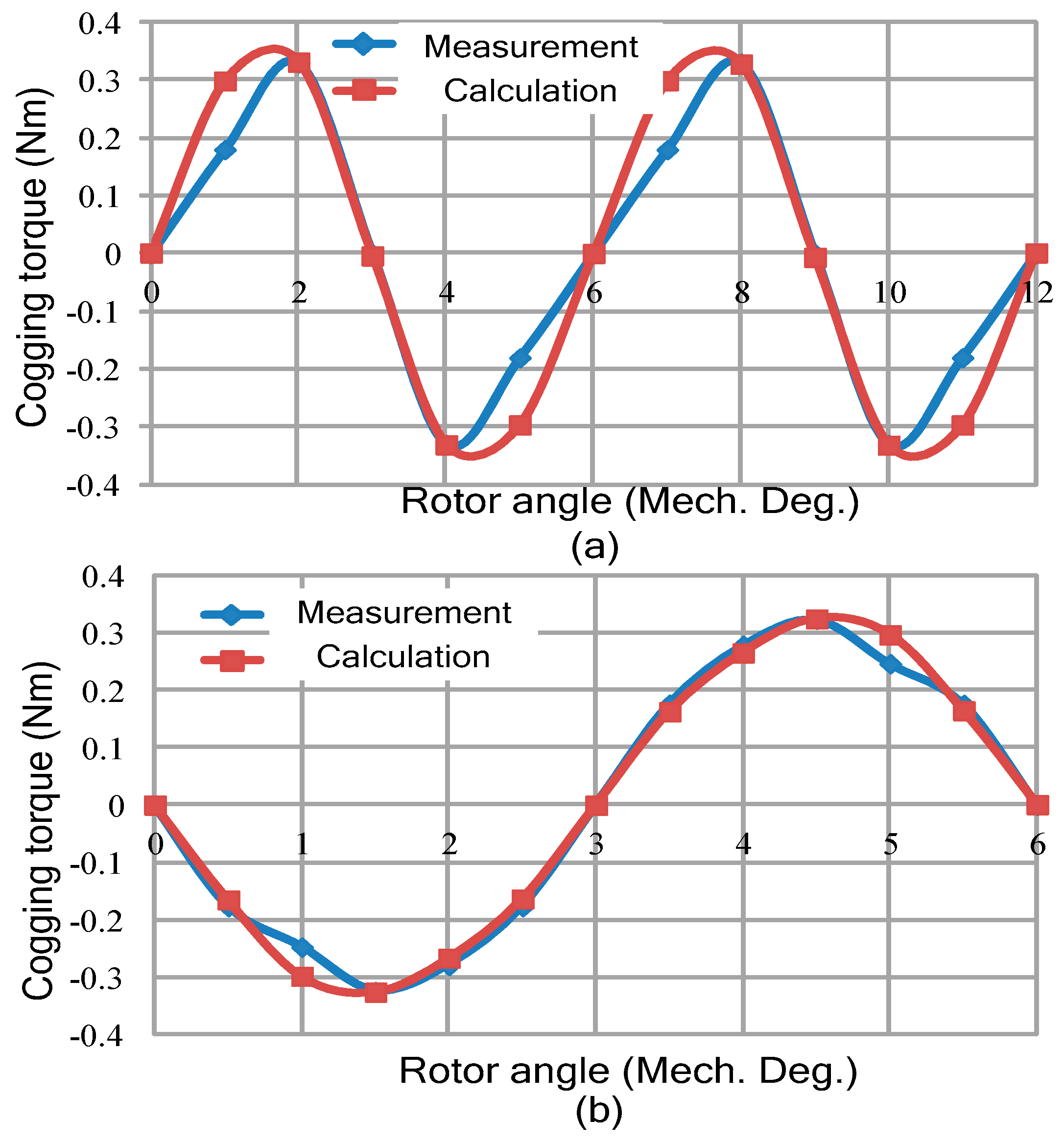
2.2. Calculation of Cogging Torque

Considering that the co-energy of the motor with a SMC core cannot be ignored, the FEM is used to calculate the cogging torque. In this paper, the commercial FEM software ANSOFT is used to calculate the cogging torque, based on the magneto static module and adaptive automatic meshing method. To accurately calculate the cogging torque, the Coulomb virtual work method is chosen, and the convergence condition is that the energy error is less than 1% of the energy from the last step. For a complete period, the cogging torque is calculated by rotating the rotor for one pitch in 12 steps. The resultant cogging torque is obtained by summing the cogging torque of three single stacks (phases) of the motor with angular shifting of 120° electrical degrees from each other.
To verify the effectiveness of this method, two examples are given. One is an outer rotor transverse flux motor, and the other is an outer rotor CPM. Both of these motors are developed with the SMC core, as shown in Figure 1.
Figure 2 shows the comparison of the measurement results and the calculation results of the resultant cogging torque of the outer rotor transverse flux motor(TFM) and outer rotor (CPM) by using the above method. As shown, the calculation results match well with the experiment results, except at the rotor position of 1 degree, which may be a result of the eddy current on the steels between the adjacent stacks.

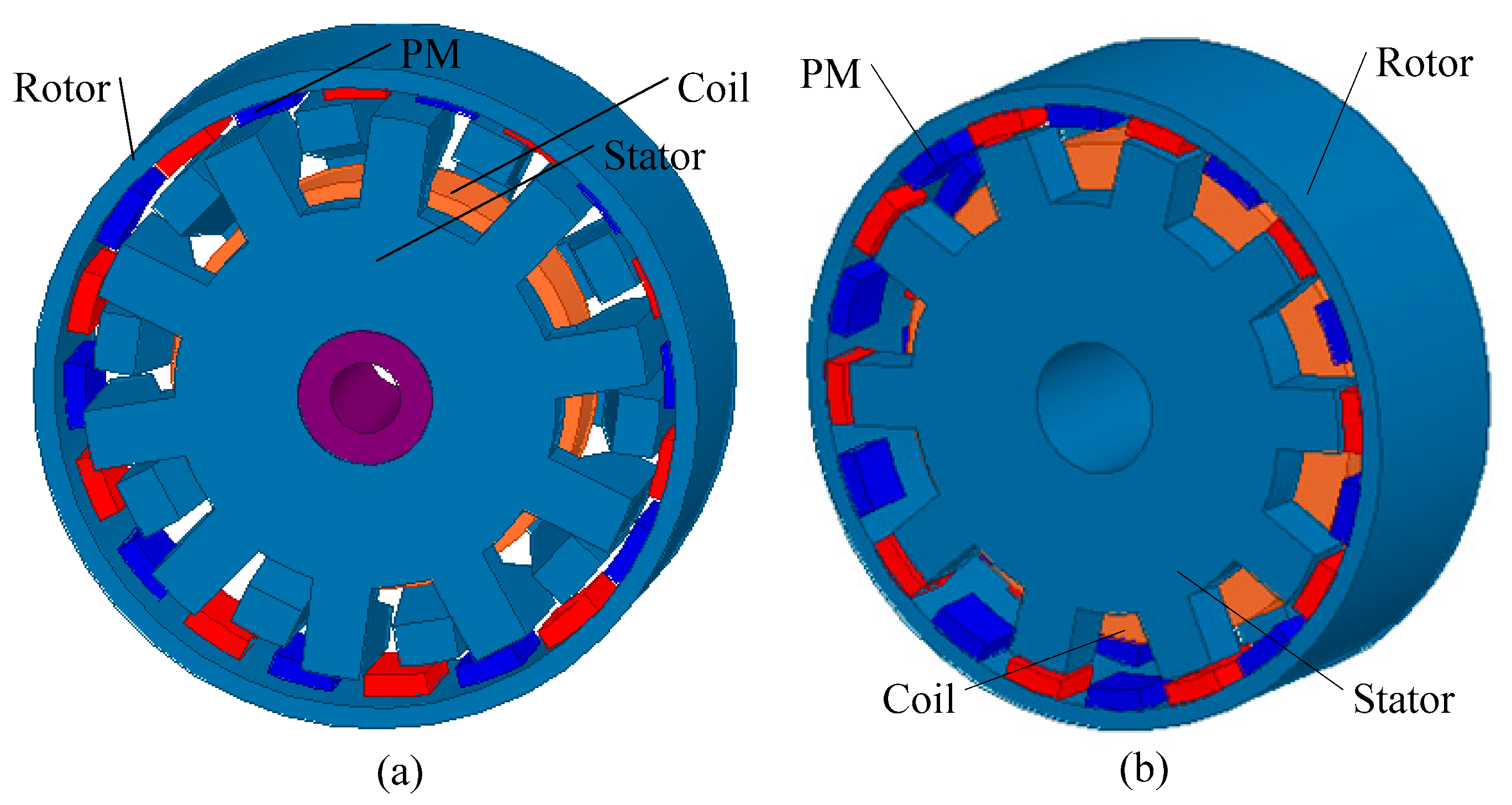
3. Claw Pole Machine with SMC Core and Cogging Torque Reduction Method

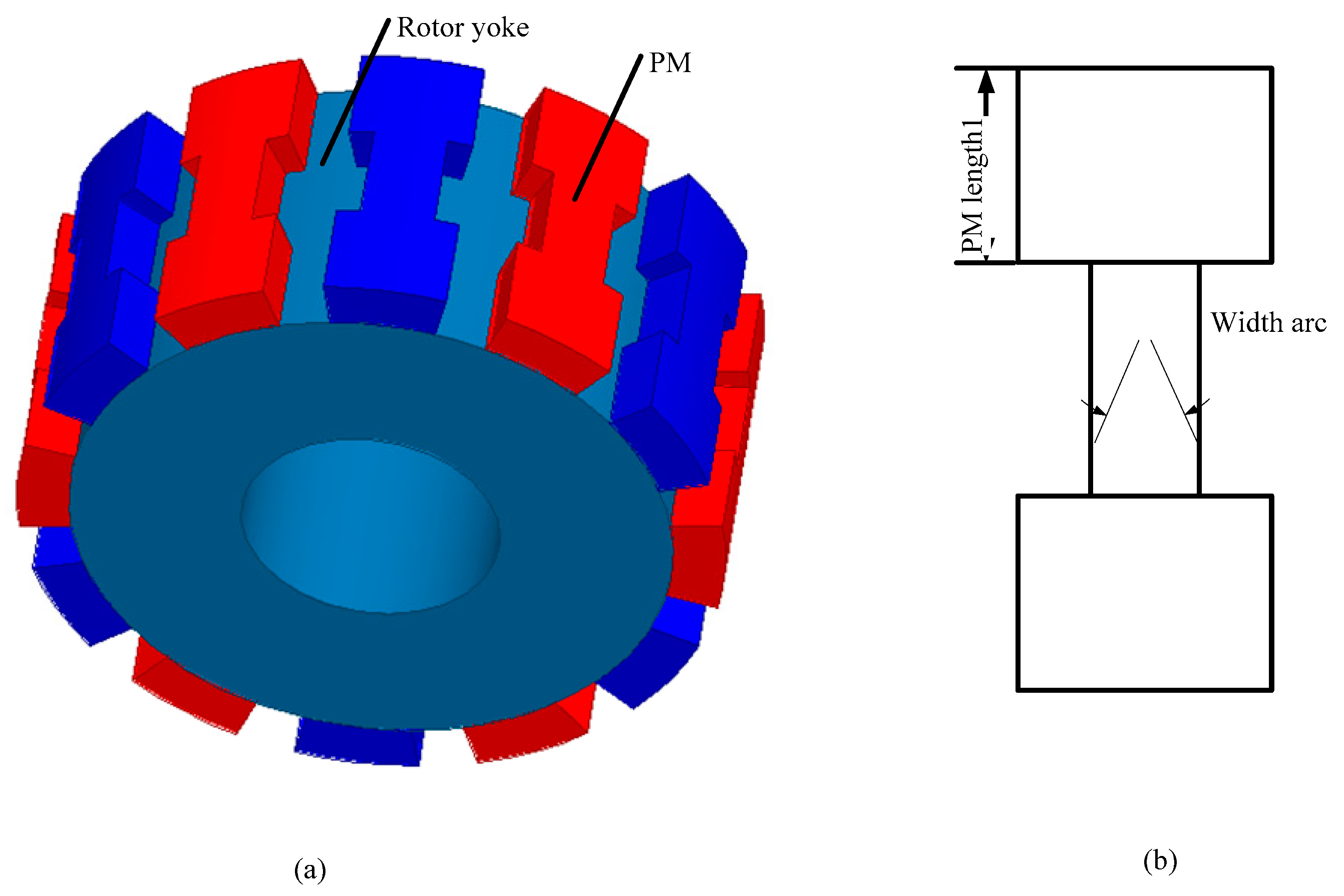
3.1. Claw Pole Machine and Its Dimension

Figure 3 shows the topology of the CPM with a SMC core, which is the single phase model. The complete machine is composed of three single-phase models, which are stacked axially with a shifting angle of 120° electrical. Each phase model consists of two disks, with the concentrated global winding in between. The rotor of CPM has 12 magnets that are surface mounted on the rotor iron core. One housing component covering the stator core is used to hold and protect the stator core. In the CPM, the material of the stator core, magnet, and rotor yoke are SOMALOY 500TM, NdFeB, and mild steel, respectively. The rated output power and speed of the CPM are 64W and 3000 rpm, respectively. The main dimensions and key parameters of CPM are listed in Table 1.
The reason that the torque density and shear stress of this CPM is very low is that the size of this motor is really small. Normally, the torque density of the motor is proportional to one third the root of its volume. This is especially true for the claw pole machine, whose torque density has the following relationship to its dimension:   T / V = V λ 2 3 , where V is the volume and λ the ratio of the axial length to outer radius. Moreover, this CPM is an initial design. In 2015, we optimized it with the multi-level optimization method, and the final EM torque was improved to 0.52 Nm, while the torque of the initial design was 0.2 Nm. The deduction process of the torque to volume and the optimization results can be seen in references [23,24].

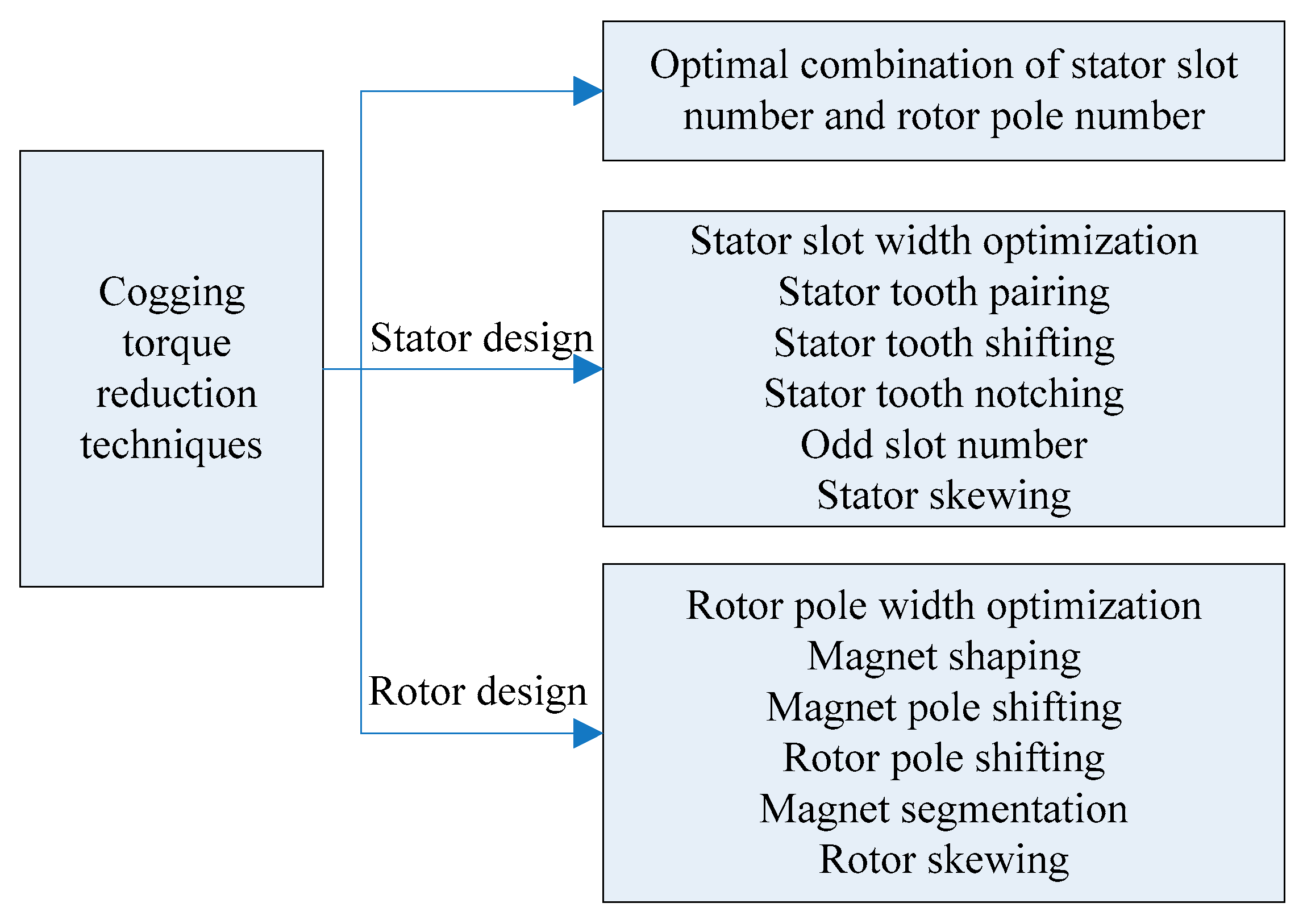
3.2. Cogging Torque Reduction Techniques in PMSM

The general cogging torque reduction techniques in PMSMs are listed in Figure 4, which are extensively applied in the axial-flux and radial-flux PMSMs. These technologies can be classified into the design of the combination of stator slot number and rotor pole number [25], stator design, and rotor design. For the stator design, it can be classified into stator slot width optimization [25], stator tooth pairing [26], stator tooth shifting [27], stator tooth notching [11], odd slot number, and stator skewing [28]. For the rotor design, it can be classified into rotor pole width optimization [3], magnet shaping [3,29], magnet pole width optimization [30,31], magnet skewing [1], magnet shifting [8], and magnet segmentation [32,33]. In this paper, the CPM is designed with three phases and six pole pairs. Through analyzing various kinds of reduction of cogging torque in technologies in radial-flux and axial-flux PMSMs, we found that some technologies are not suitable for the CPM, e.g., the stator tooth skewing. The technologies that can be used to reduce the cogging torque of CPMs include stator pole optimization, stator tooth notching, magnet step skewing, magnet axial pole pairing, and magnet shifting; these are investigated and compared in this paper.

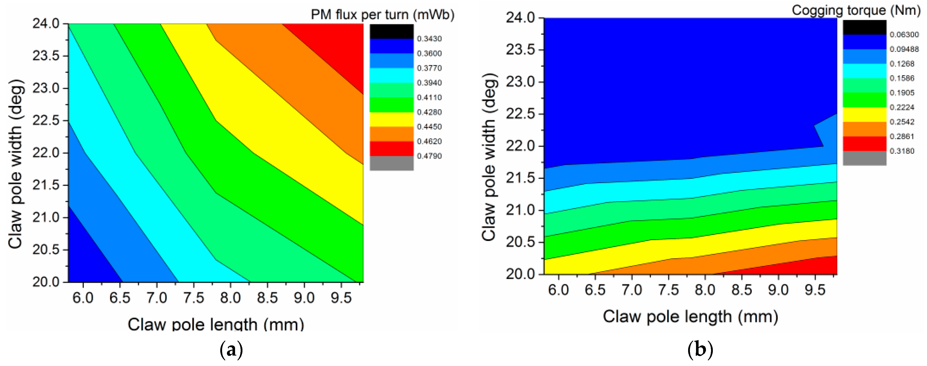
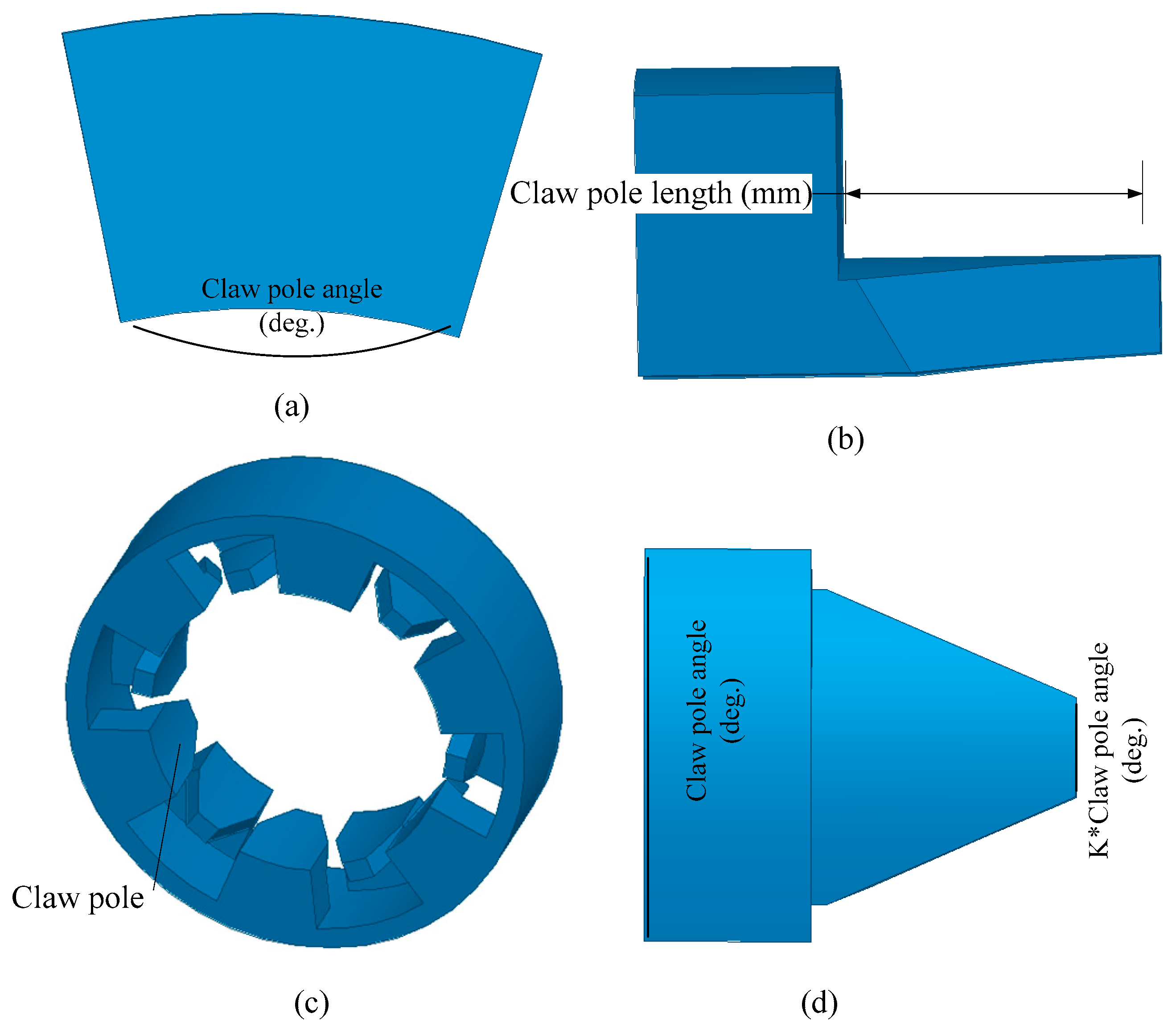
4. Reduction of Cogging Torque by Changing the Claw Pole Shape

Depending on the ways to reduce the cogging torque of CPMs, the technologies can be classified into: (1) optimizing the stator shape, and (2) optimizing the magnet on the rotor. In this section, the claw pole shape optimizations including the claw pole dimensions and claw pole structure are investigated.

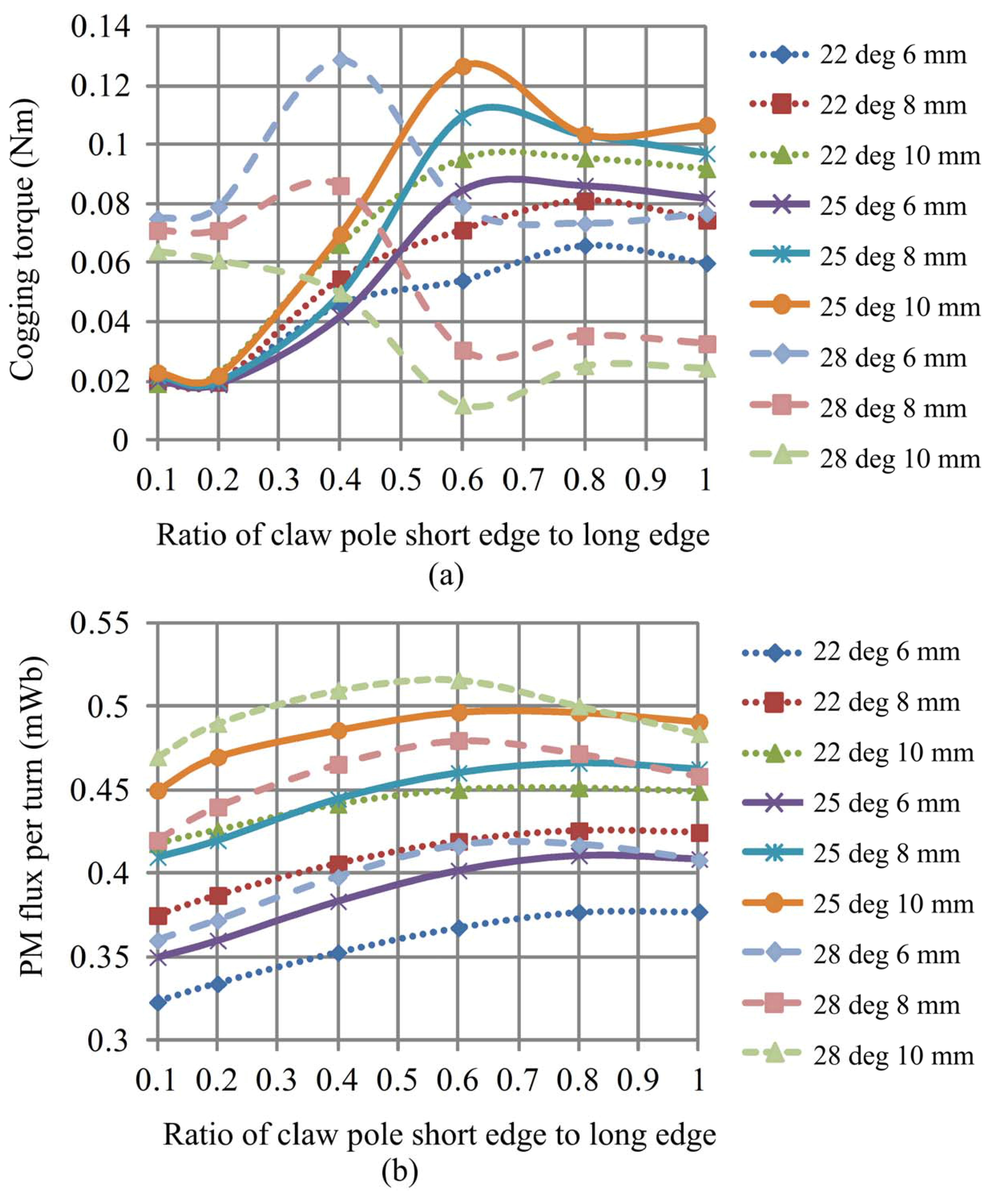
4.1. Claw Pole Dimension

Since the cogging torque is produced by the interaction between the magnet poles and the stator slots, both the dimensions of the claw pole and the magnet have a great influence on the cogging torque of CPMs. Reducing the claw pole arc and claw pole length can reduce the cogging torque of a CPM, while the PM flux will be reduced as well. Figure 5 shows the definition of claw pole dimensions, including the claw pole arc and claw pole length.
By using the FEM software ANSOFT, the cogging torque and PM flux of CPMs with variations in claw pole dimensions can be predicted. The variation of claw pole arc ranges from 20 degrees to 24 degrees, and that of claw pole length ranges from 5.8 mm to 9.8 mm. Figure 6 shows the peak value of PM flux and the peak-to-peak value of cogging torque. As shown, the claw pole length has a slight impact on the cogging torque when compared with the claw pole arc. The peak-to-peak value of the cogging torque is 0.0635 Nm, when the claw pole length is 5.8 mm and the claw pole arc is 22 degrees. For the main PM flux, the greater the claw pole length and claw pole arc, the higher the PM flux. The PM flux per turn is 0.4787 mWb when the claw pole length is 9.8 mm and the claw pole arc is 24 degrees.

4.2. Unequal Width Claw Pole Structure

For the traditional CPM, the claw pole tooth is usually designed with the unequal width of the claw pole to reduce the cogging torque, as shown in Figure 7. Figure 7 also illustrates the schematic diagram of the CPM with unequal width claw pole and the definitions of its main dimensions. The pole arc of the stator wall is defined as θ, and the ratio of the short edge to the long edge of the claw pole is defined as K. In most cases, K is designed lower than 1, as that kind of CPM can produce relatively high PM torque and relatively low cogging torque.
By using the ANSOFT software, the cogging torque and PM flux of the CPM with the variation of the claw pole arc, the ratio of the short edge to the long edge of the claw pole, and the claw pole length can be calculated. The variation of claw pole arc ranges from 22 to 28 degrees, which is divided into three levels. K ranges from 0.1 to 1, which is divided into nine levels. The claw pole length ranges from 6 mm to 10 mm, which is divided into three levels.
Figure 8 shows the magnitude of the cogging torque and PM flux per turn of the CPM with the variation of the different dimensions. It can be found that K has the greatest impact on the cogging torque when compared with the other parameters. When the pole arc ranges from 22to 25 degrees, the minimum cogging torque can be obtained when K equals 0.2. When the pole arc equals 28 degrees, the minimum cogging torque can be achieved when K equals 0.6. For the PM flux per turn, in general, the greater the pole arc, claw pole length, and the K, the higher the PM flux per turn.

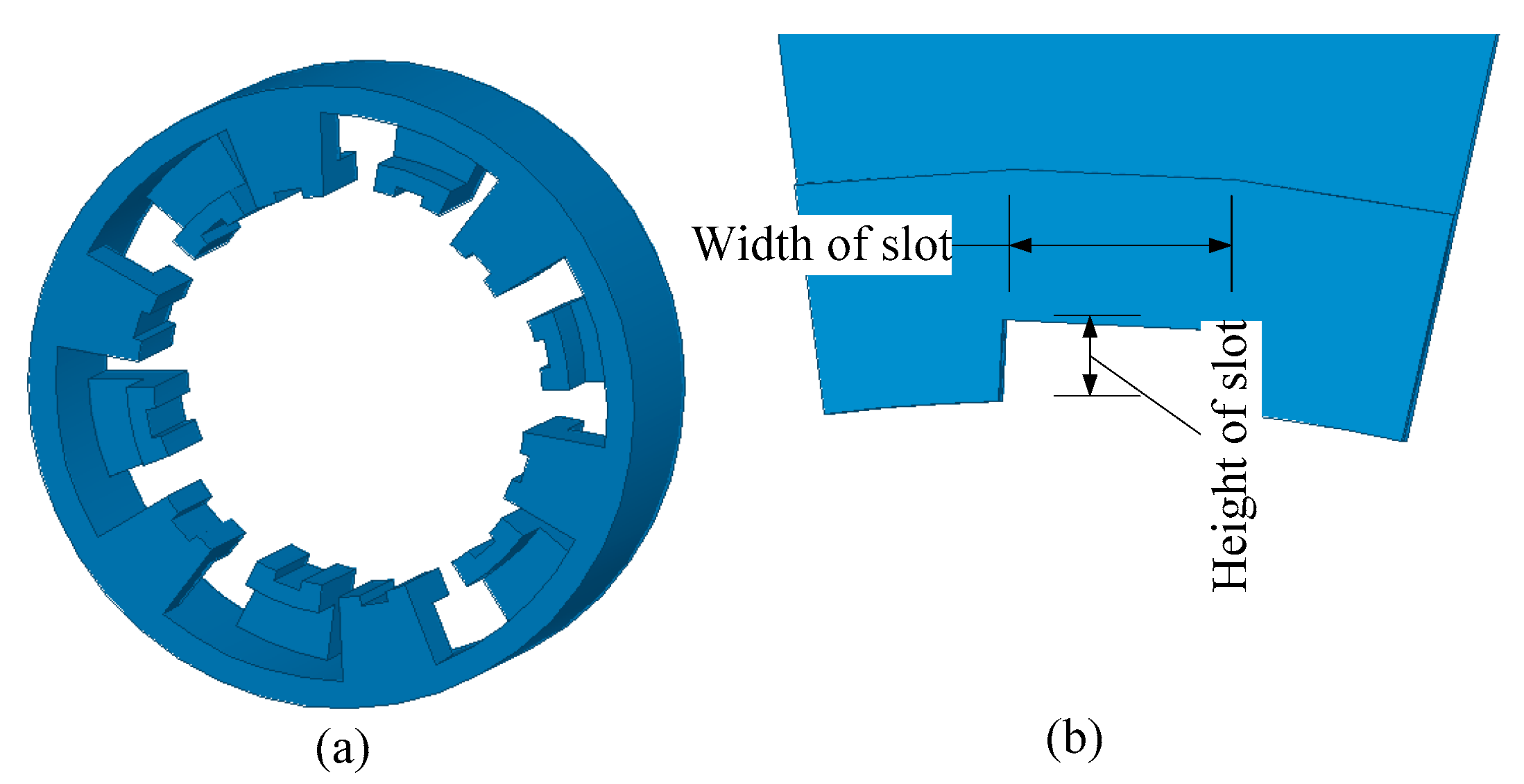
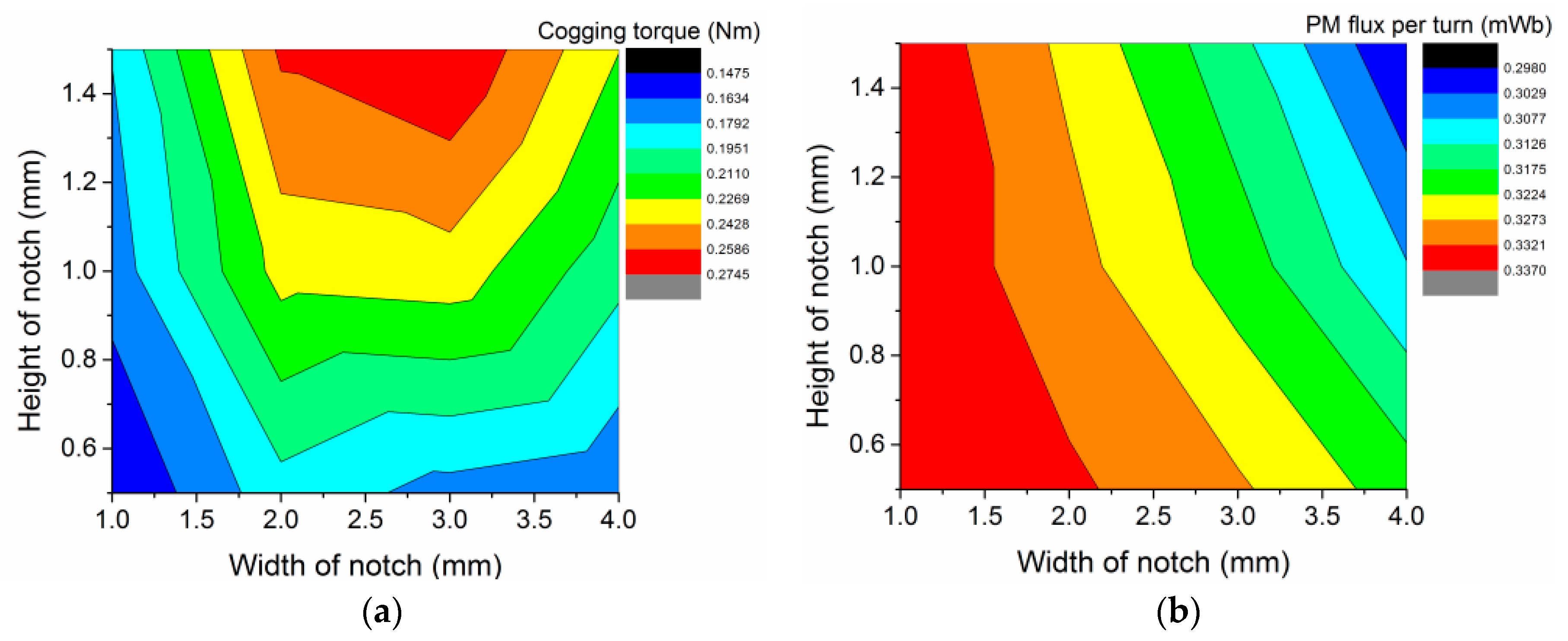
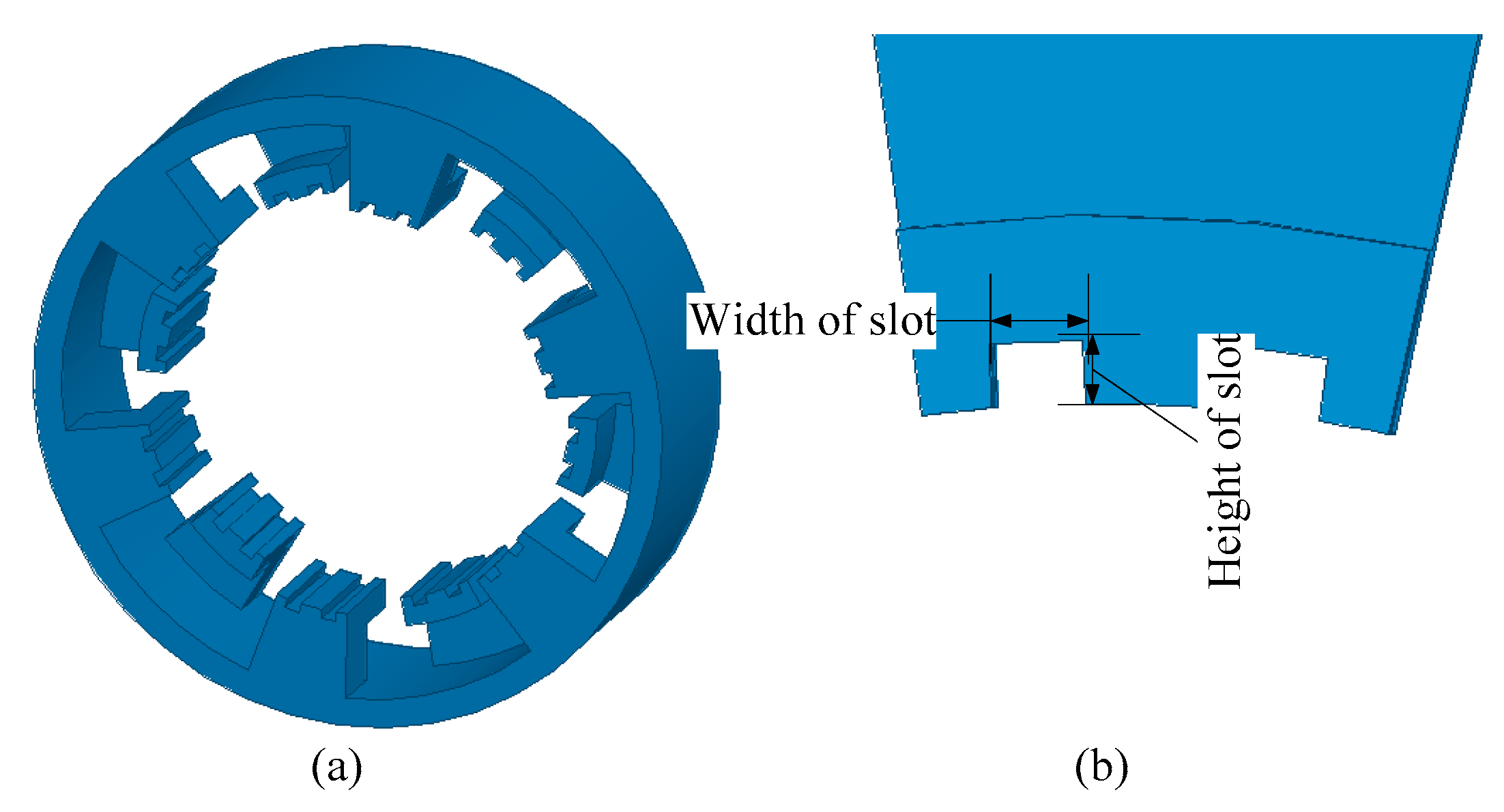
4.3. Stator Tooth Notching

Stator tooth notching is an effective way to reduce the cogging torque in the PMSM, and it was widely used in various radial-flux PMSMs [22,28]. Compared with the stator tooth skewing technology, the manufacturing cost of the stator tooth notching is much lower. However, with the cogging torque reduction, the effective PM fluxes will usually be reduced greatly by using the stator tooth notching, as the equivalent air gap is enlarged. Two kinds of stator tooth notching technologies of CPM are investigated: one is that each stator tooth is notched by one slot, and the other is that each stator tooth is notched by two slots.
Figure 9 shows the schematic diagram of the CPM with one slot stator tooth and the dimensions of the slot. Figure 10 shows the magnitude of the cogging torque and the PM flux of the CPM with the variation of the dimensions of the one-slot stator tooth. It can be found that the magnitude of the PM flux of the CPM decreases when the slot becomes larger. The cogging torque of the CPM with the slot width of 1 mm and slot height of 0.5 mm is the minimum.
Figure 11 shows the schematic diagram of the CPM with the two-slot stator tooth, and its dimensions. Figure 12 shows the waveforms of the cogging torque and PM flux of CPM, as predicted by FEM. With the acceptable dimensions of the slots developed to the stator tooth, where the height of the slot ranges from 0.5 mm to 1 mm and the width of the slot ranges from 0.5 mm to 1 mm, the peak value of the cogging torque of single-phase (stack) CPM and three-phase CPM change very little when the dimensions of the slot are changed. In addition, it has a slight impact on the PM flux.
Both the one-slot and two-slot notching on the stator tooth of the CPM are investigated. It can be found that the effect of the stator tooth notching of the CPM with a SMC is little, particularly for the two slots implemented on the stator claw pole. The main reason is that the permeability of the SMC is much lower than that of silicon steel. Thus, the slotting of the stator pole has little impact on the equivalent air gap.

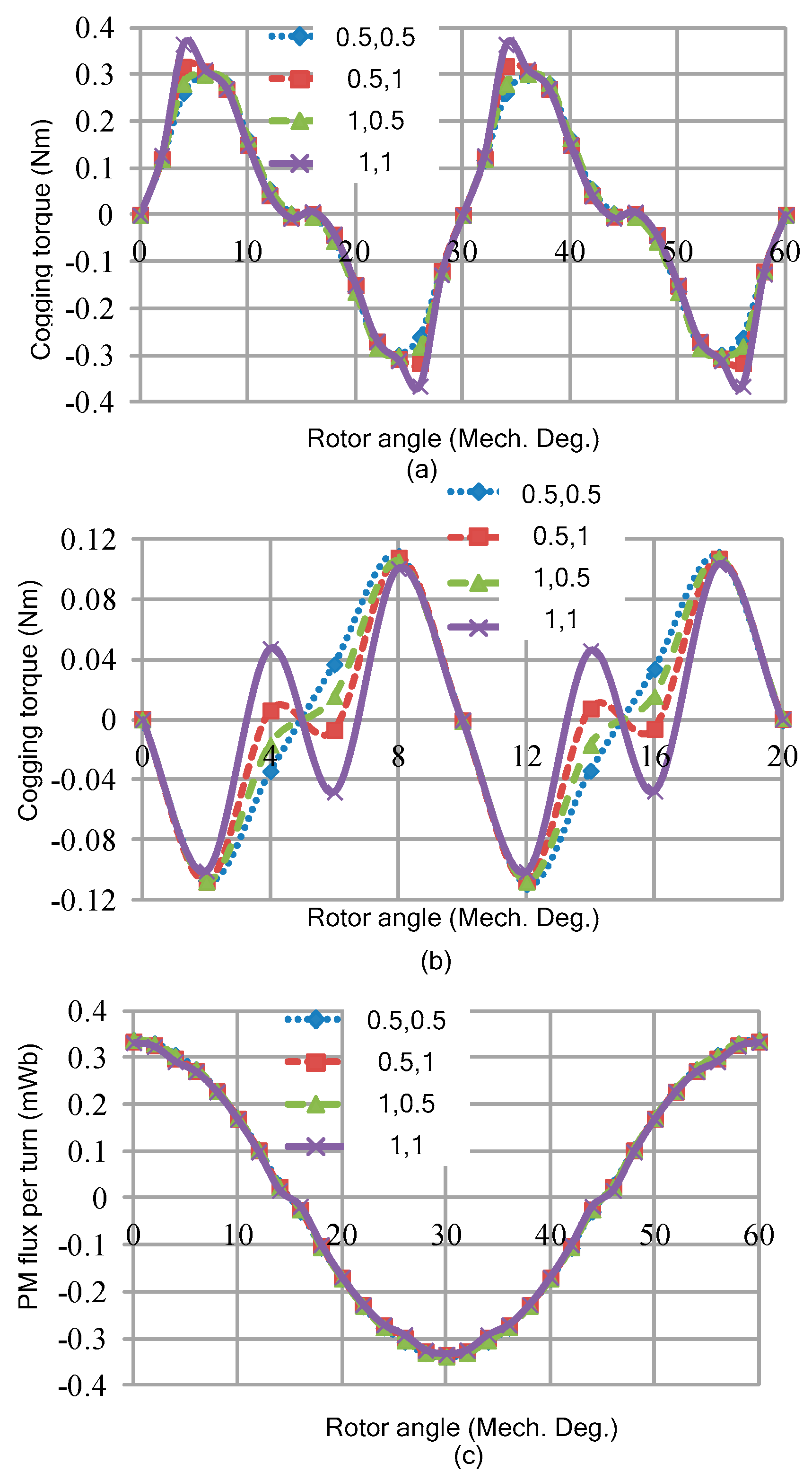
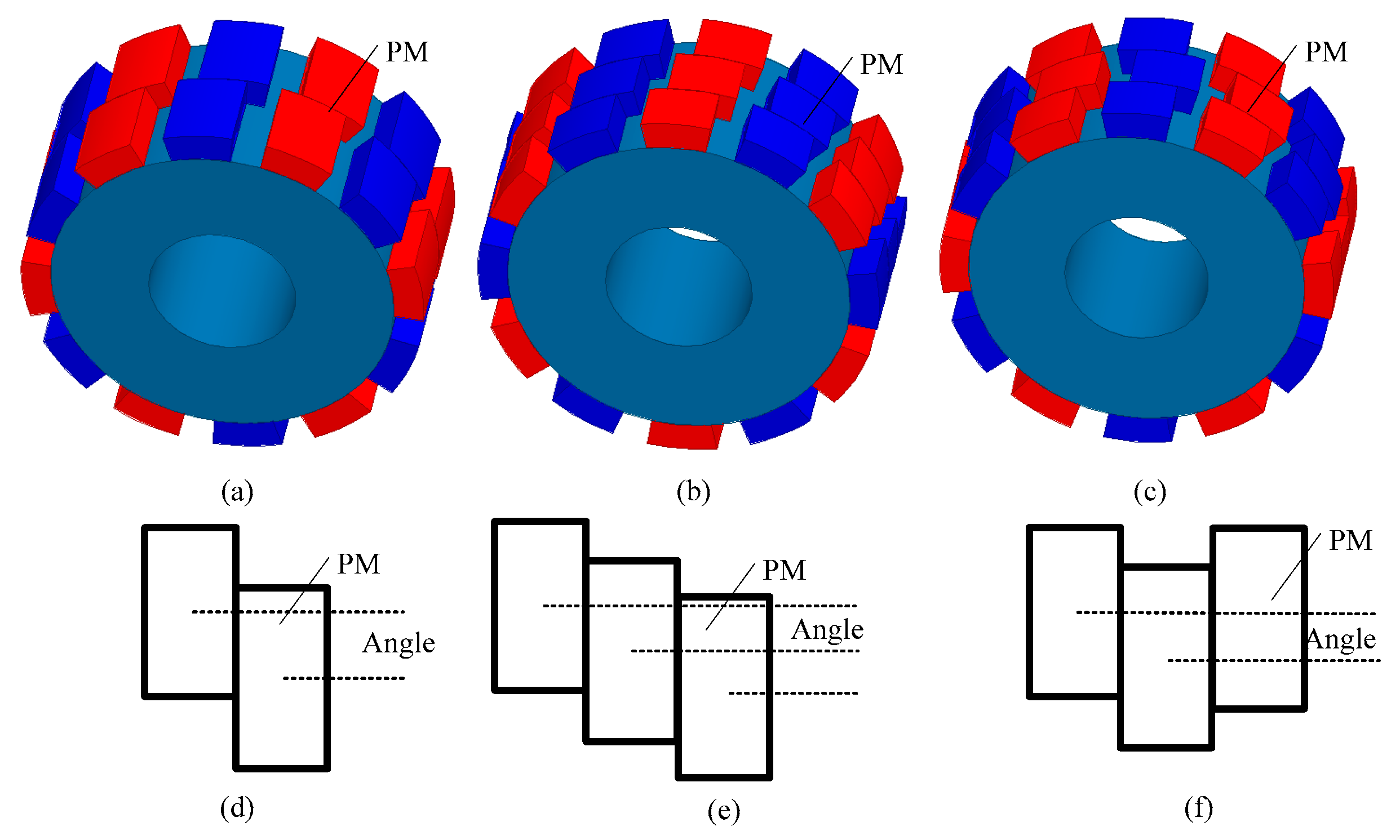
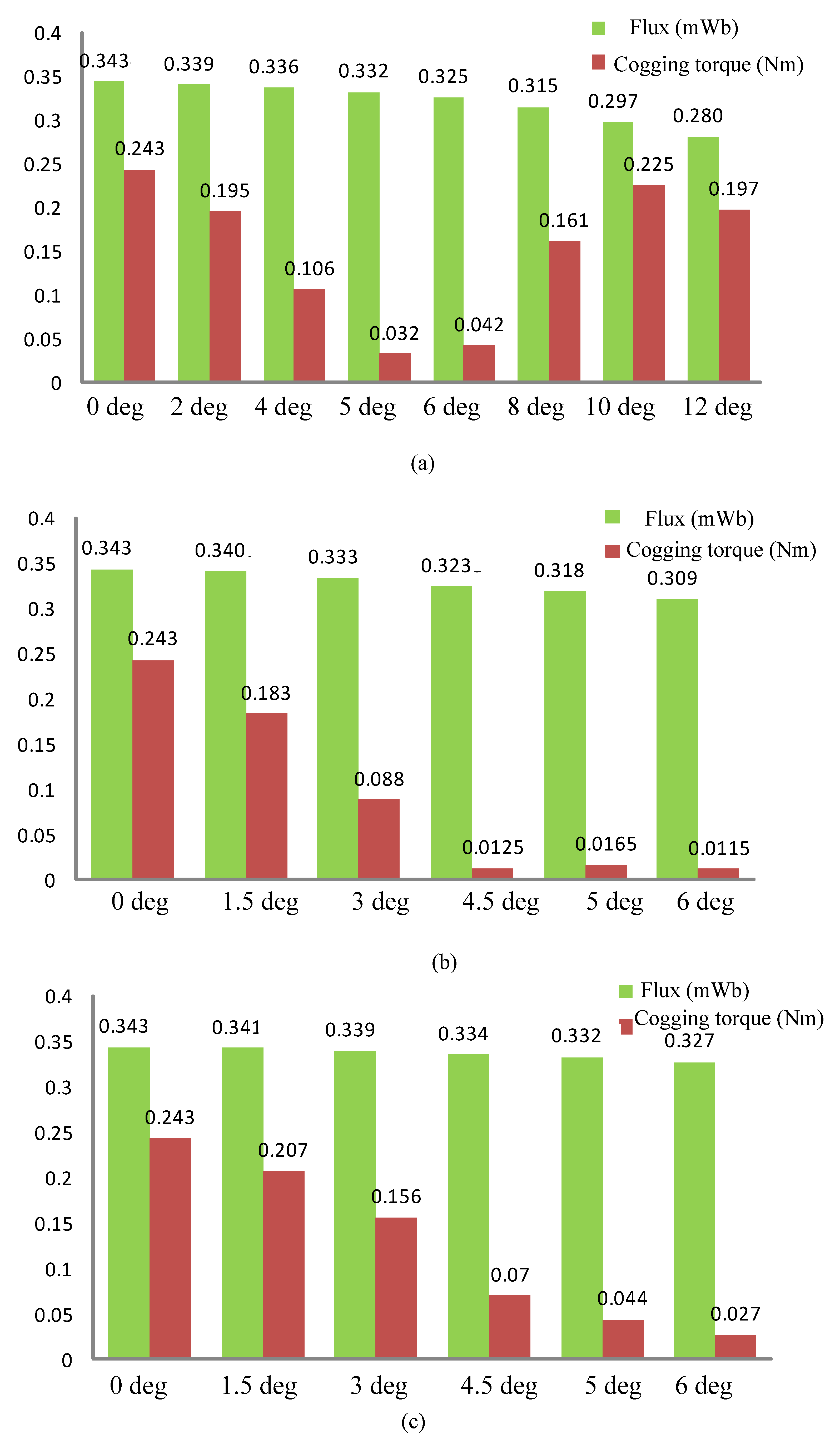
5. Reduction of Cogging Torque by Using Magnet Step Skewing

Skewing is a general method that can be used to reduce the cogging torque of PMSMs. For the traditional PMSM, both the stator tooth and magnet can be skewed to reduce the cogging torque. In the traditional PMSM, skewing the stator tooth will increase the difficulty of manufacturing. Compared with skewing the stator tooth, skewing the magnet on the rotor is more convenient. Meanwhile, in the CPM, it is very difficult to put two single-skewed stator cores together to form one phase stator core. Therefore, the magnet skewing method is chosen to reduce the cogging torque of the CPM. However, the manufacturing cost of skewing the magnet continuously is very high. The magnet step skewing is adopted in the CPM for achieving the low cogging torque with the acceptable manufacturing cost.
Figure 13 shows the general magnet skewing methods and the definitions of various skewing angles: (a,b) show traditional rotor step skewing, (c) is the herringbone step skewing, and (d–f) are the angle definitions of the above rotor skewing, respectively. By using the simplified analytical analysis method to analyze the effect of the skewing angle to the cogging torque, it can be found that the minimum cogging torque can be achieved when the magnet-skewing angle equals 5 degrees.
Figure 14 compares the results of the PM flux per turn and the cogging torque of the CPM with three different magnet-skewing technologies. It can be found that the minimum cogging torque can be achieved when the traditional three-step magnet skewing is adopted, where the skewing angle is 6 degrees.
Among these methods, the performance of the CPM with traditional three-step magnet skewing is better than that of the CPM with traditional two-step magnet skewing. Compared with the traditional three-step magnet skewing technology, the herringbone two-step magnet skewing can provide higher PM flux per turn with the acceptable cogging torque.

6. Reduction of Cogging Torque by Using Magnet Axial Pairing and Magnet Shifting

6.1. Magnet Axial Pairing

Magnet axial pairing can be used to reduce the cogging torque in the PMSM, as it can comprise the different magnet axial length and the different magnet width arc. Different from the traditional axial pole pairing technology, a novel magnet axial paring is proposed to reduce the cogging torque of the CPM. Figure 15 shows the structure of magnet axial pairing; the magnet of the middle part can be changed for different width arcs and axial lengths, while in the traditional axial pole paring in PMSM, only the end part of the magnet will be changed for different width arcs and axial lengths. Considering that the magnet located under the stator wall contributes to the main PM flux, the novel magnet axial pairing should be much more suitable for the CPM. Its performance is thus investigated. Figure 15b shows the definition of the parameters of magnet axial pole pairing in CPM.
In this section, the PM length and width arc of the magnet vary from 4.3 mm to 7.3 mm, and 9 degrees to 18 degrees, respectively. Each parameter is divided into four levels. The magnitude of cogging torque and the PM flux per turn are illustrated in Figure 16. It can be found that the width arc of the magnet has a greater impact on the cogging torque than that of the PM length. For the PM flux per turn, it is decreases with the PM length, and width arc decreases. The minimum cogging torque can be achieved when the pole arc and PM length equal 9 degrees and 6.3 mm, respectively.

6.2. Magnet Shifting

Magnet shifting is another traditional method that can be used to reduce the cogging torque in PMSMs. Compared with magnet step skewing, the manufacturing cost of the CPM with the magnet shifting is much lower, and the structure is stronger. The definition of magnet shifting angle is illustrated in Figure 17.
Figure 18 shows the magnitude of PM flux per turn and the cogging torque of a three-phase CPM. It can be found that the minimum cogging torque is 0.021 Nm when the magnet shifts 5 degrees, while its PM flux per turn is 0.331 mWb.

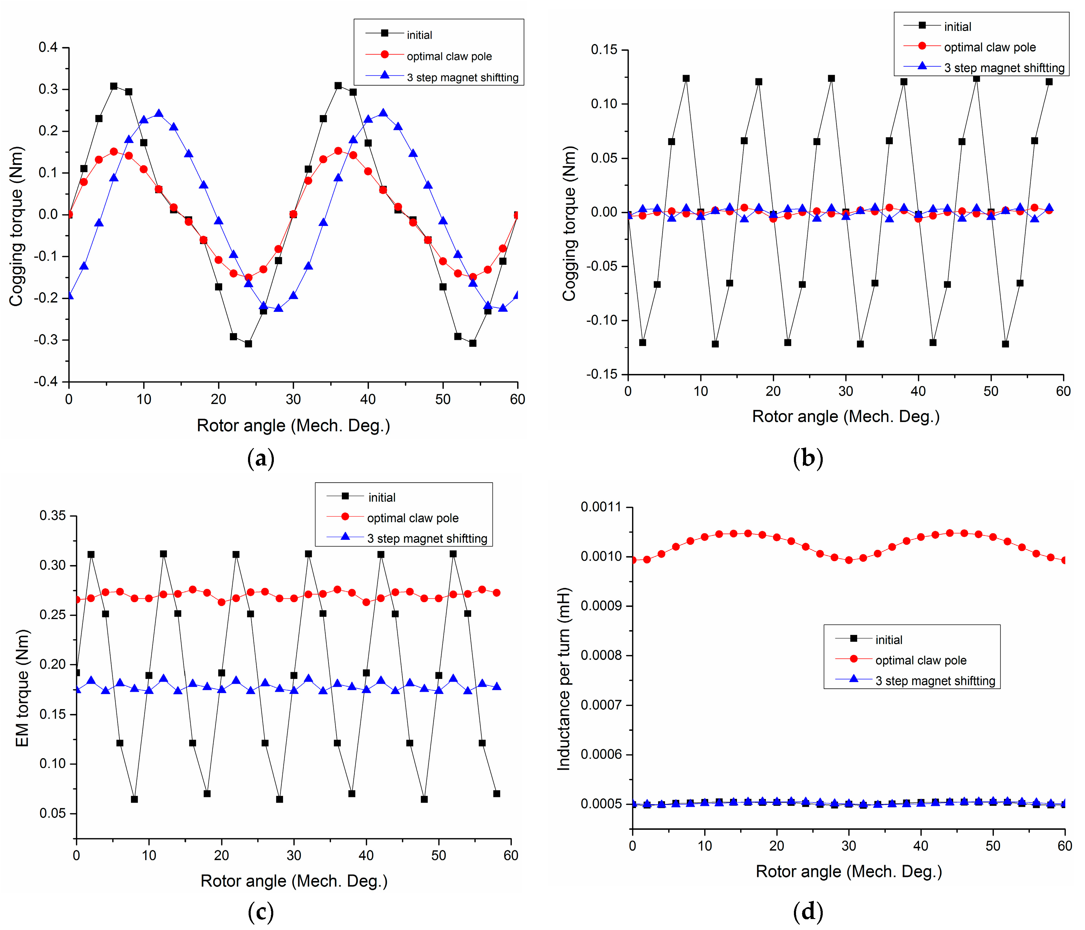
7. Performance Comparison and Discussion

In this section, the effects of various methods that can be used to reduce the cogging torque of CPM, namely, optimal claw pole dimensions, unequal width claw pole, stator tooth notching, magnet skewing, magnet axial pairing and magnet shifting are investigated, compared, and discussed. In order to have a quantitative comparison, a simple target equation is proposed as
f = T c o g Φ p m
where Tcog is the peak value of the resultant cogging torque, and Φpm is the PM flux per turn. The reason for choosing the PM flux per turn is that the electromagnetic torque ability is proportional to the PM flux per turn. To ensure that the CPM with the reduced cogging torque can provide acceptable output torque, the constraints of the candidates need to meet
{ Φ p m 0.9 Φ p m o T c o g 0.25 T c o g o
where Φpmo is the PM flux of the original motor, and Tcogo is the cogging torque of the original motor.
By using these comparison rules, the best solutions for each method are listed in Table 2. The design of the unequal width CPM has a claw pole arc of 28 degrees, ratio of short edge to long edge of 0.6, and claw pole length of 10 mm. The design of the two-step magnet skewing angle of the CPM is 6 degrees, the design of three-step magnet skewing angle of the CPM is 4.5 degrees, and for the herringbone magnet skewing, the angle is 6 degrees. The design of the magnet-shifting angle of the CPM is 5 degrees. The optimized dimensions for the claw pole area claw pole length of 9.8 mm, and a claw pole arc of 24 degrees.
As shown in Table 2, the effects of the CPM with unequal width claw pole can achieve the best Tcog/Fpm, and the three-step magnet skewing of the CPM is second best. The cogging torque and PM flux per turn of the initial CPM is 0.243 Nm and 0.343 mWb, respectively. In comparison, the cogging torque and PM flux per turn of the CPM with three-step magnet skewing is 0.012 Nm and 0.329 mWb, where the cogging torque is 5% of that of the initial CPM, and the PM flux per turn is 95% of that of the initial CPM. Furthermore, it can be predicted that the CPM with the combination of unequal width claw pole and multi-step magnet skewing can obtain good output torque with very low cogging torque.
The overall performance comparison of the CPM with the initial design, the optimal unequal stator claw pole design and the three-step magnet shifting design are shown in Figure 19. Here, it can be seen that the cogging torque of the initial CPM is very high, though the cogging torque of the three-phase CPM can be much lower than that of the one-phase CPM. The maximum cogging torque of the initial CPM is about 0.245 in peak-to-peak value, which can be a handicap for the motor starting, since the rated Electromagnetic (EM) torque of the initial CPM is about 0.2 Nm. As show in Figure 19b, the torque ripple of the initial CPM is very high, which is the reason why we need to reduce the cogging torque of this kind of small CPM. With the optimization, it be seen found that the cogging torque and the torque ripple of the CPM can be reduced greatly with the above two methods (three-step magnet shifting and unequal stator claw pole width).Moreover, the inductance of the CPM with optimal claw pole teeth increased a lot, since the flux leakage increased. The comparison of the inductance can be seen in Figure 19d. In this paper, we show the inductance of per-turn winding; for the inductance per winding, it should be multiplied with the square of the number of turns. In the view of the power factor, the power factor of the CPM with three-step magnet shifting is quite similar to that of the initial CPM. However, the power factor of the CPM with the optimal claw pole teeth design is only about 0.85 of that of the initial CPM.

8. Conclusions

Various cogging torque reduction techniques that have been used in axial-flux and radial-flux PMSMs are developed for reducing the cogging torque of CPMs with SMCs. These techniques are divided into the stator design and rotor design. By using the 3-D FEM software, the effects of the various techniques are analyzed, particularly on the PM flux per turn and resultant cogging torque. As the permeability of SMC is much lower than that of silicon steel, some methods that can well reduce the cogging torque in radial-flux PMSMs with silicon steels are not suitable for the CPM with SMC, e.g., stator tooth notching. The axial pole pairing method that has been used to reduce the cogging torque of radial-flux PMSMs is redesigned and developed in a CPM. It can be found that most optimized techniques can achieve the PM flux of no lower than 95% of the initial design, with the cogging torque of much lower than 25% of the initial design. By comparing the effectiveness of each method, it can be found that the CPM with the unequal width claw pole and three-step magnet skewing can achieve the lowest cogging torque. The optimized skewing angle and shifting angle of the magnet skewing and magnet shifting match well with the Fourier analysis, where the value is around 5 degrees.

Acknowledgments

National Natural Science Foundation of China under Projects 51377042.

Author Contributions

All authors contributed to this work by collaboration. Chengcheng Liu is the main author of this manuscript; Jiawei Lu, and Gang Lei assisted to establish the finite element model and perform the simulations; Youhua Wang, Jianguo Zhu and Youguang Guo provided some useful suggestions in the construction of paper. All authors revised and approved the publication.

Conflicts of Interest

The authors declare no conflict of interest.

References

  1. Fei, W.; Zhu, Z.Q. Comparison of cogging torque reduction in permanent magnet brushless machines by conventional and herringbone skewing techniques. IEEE Trans. Energy Convers. 2013, 28, 664–674. [Google Scholar] [CrossRef]
  2. Bianchi, N.; Bolognani, S. Design techniques for reducing the cogging torque in surface-mounted PM motors. IEEE Trans. Ind. Appl. 2002, 38, 1259–1265. [Google Scholar] [CrossRef]
  3. Aydin, M.; Zhu, Z.Q.; Lipo, T.A.; Howe, D. Minimization of cogging torque in axial-flux permanent-magnet machines: Design concepts. IEEE Trans. Magn. 2007, 43, 3614–3622. [Google Scholar] [CrossRef]
  4. Schmidt, E. 3-D finite element analysis of the cogging torque of a transverse flux machine. IEEE Trans. Magn. 2005, 41, 1836–1839. [Google Scholar] [CrossRef]
  5. Yan, J.; Lin, H.; Zhu, Z.Q.; Jin, P.; Guo, Y. Cogging torque optimization of flux switching transverse flux permanent magnet machine. IEEE Trans. Magn. 2013, 49, 2169–2172. [Google Scholar] [CrossRef]
  6. Wu, L.J.; Zhu, Z.Q.; Staton, D.A.; Popescu, M.; Hawkins, D. Comparison of analytical models of cogging torque in surface-mounted PM machines. IEEE Trans. Ind. Electron. 2012, 59, 2414–2425. [Google Scholar] [CrossRef]
  7. Lin, D.; Ho, S.L.; Fu, W.N. Analytical prediction of cogging torque in surface-mounted permanent-magnet motors. IEEE Trans. Magn. 2009, 45, 3296–3302. [Google Scholar] [CrossRef]
  8. Dosiek, L.; Pillay, P. Cogging torque reduction in permanent magnet machines. IEEE Trans. Ind. Appl. 2007, 43, 1565–1571. [Google Scholar] [CrossRef] [Green Version]
  9. Niguchi, N.; Hirata, K. Cogging torque analysis of magnetic gear. IEEE Trans. Ind. Electron. 2012, 59, 2189–2197. [Google Scholar] [CrossRef]
  10. Gulec, M.; Aydin, M. Reduction of cogging torque in double-rotor axial flux permanent magnet disc motors: A review of cost effective magnet skewing techniques with experimental verification. IEEE Trans. Electron. 2013, 61, 5025–5034. [Google Scholar]
  11. Bianchini, C.; Immovilli, F.; Lorenzani, E.; Bellini, A.; Davoli, M. Review of design solutions for internal permanent-magnet machines cogging torque reduction. IEEE Trans. Magn. 2012, 48, 2685–2693. [Google Scholar] [CrossRef]
  12. Zhu, Z.; Liu, Y.; Howe, D. Minimizing the influence of cogging torque on vibration in PM brushless machines by direct torque control. IEEE Trans. Magn. 2006, 42, 3512–3514. [Google Scholar] [CrossRef]
  13. Liu, T.; Huang, S.; Gao, J.; Lu, K. Cogging torque reduction by slot-opening shift for permanent magnet machines. IEEE Trans. Magn. 2013, 49, 4028–4031. [Google Scholar] [CrossRef]
  14. Choi, J.S.; Izui, K.; Nishiwaki, S.; Kawamoto, A.; Nomura, T. Topology optimization of the stator for minimizing cogging torque of IPM motors. IEEE Trans. Magn. 2011, 47, 3024–3027. [Google Scholar] [CrossRef]
  15. Lee, J.Y.; Chang, J.H.; Kang, D.H.; Kim, S.I.; Hong, J.P. Tooth shape optimization for cogging torque reduction of transverse flux rotary motor using design of experiment and response surface methodology. IEEE Trans. Magn. 2007, 43, 1817–1820. [Google Scholar] [CrossRef]
  16. Gašparin, L.; Černigoj, A.; Markič, S.; Fišer, R. Additional cogging torque components in permanent-magnet motors due to manufacturing imperfections. IEEE Trans. Magn. 2009, 45, 1210–1213. [Google Scholar] [CrossRef]
  17. Guo, Y.; Zhu, J.; Dorrell, D.G. Design and analysis of a claw pole permanent magnet motor with molded soft magnetic composite core. IEEE Trans. Magn. 2009, 45, 4582–4585. [Google Scholar]
  18. Zhu, J.G.; Guo, Y.G.; Lin, Z.W.; Li, Y.J.; Huang, Y.K. Development of PM transverse flux motors with soft magnetic composite cores. IEEE Trans. Magn. 2011, 47, 4376–4383. [Google Scholar] [CrossRef]
  19. Deodhar, R.P.; Pride, A.; Bremner, J.J. Design method and experimental verification of a novel technique for torque ripple reduction in stator claw-pole PM machines. IEEE Trans. Ind. Appl. 2015, 51, 3743–3750. [Google Scholar] [CrossRef]
  20. Masmoudi, A.; Njeh, A.; Mansouri, A.; Trabelsi, H.; Elantably, A. Optimizing the overlap between the stator teeth of a claw poletransverse-flux permanent-magnet Machine. IEEE Trans. Magn. 2004, 40, 1573–1578. [Google Scholar] [CrossRef]
  21. Pompermaier, C.; Washington, J.; Sjöberg, L.; Ahmed, N. Reduction of cogging torque in transverse flux machines by stator and rotorpoleshaping. In Proceedings of the 2016 IEEE Conference on Energy Conversion Congress and Exposition (ECCE), Milwaukee, WI, USA, 18–22 September 2016; pp. 1–7. [Google Scholar]
  22. Ueda, Y.; Takahashi, H.; Ogawa, A.; Akiba, T.; Yoshida, M. Cogging-Torque Reduction of Transverse-Flux Motor by Skewing Stator Poles. IEEE Trans. Magn. 2016, 52. [Google Scholar] [CrossRef]
  23. Liu, C.C.; Lei, G.; Wang, T.S.; Guo, Y.G.; Wang, Y.H.; Zhu, J.G. Comparison of electrical machines with SMC core. IEEE Trans. Ind. Electron. 2017, 64, 1049–1060. [Google Scholar] [CrossRef]
  24. Lei, G.; Liu, C.C.; Zhu, J.G.; Guo, Y.G. Techniques for multilevel design optimization of permanent magnet motors. IEEE Trans. Energy Convers. 2015, 30, 1574–1584. [Google Scholar] [CrossRef]
  25. Zhu, Z.Q.; Howe, D. Influence of design parameters on cogging torque in permanent magnet machines. IEEE Trans. Energy Convers. 2000, 15, 407–412. [Google Scholar] [CrossRef]
  26. Hwang, S.-M.; Eom, J.-B.; Hwang, G.B.; Jeong, W.-B.; Jung, J.-H. Cogging torque and acoustic noise reduction in permanent magnet motors by teeth pairing. IEEE Trans. Magn. 2000, 36, 3144–3146. [Google Scholar] [CrossRef]
  27. Wang, D.; Wang, X.; Qiao, D.; Pei, Y.; Jung, S.Y. Reducing cogging torque in surface-mounted permanent-magnet motors by nonuniformly distributed teeth method. IEEE Trans. Magn. 2011, 47, 2231–2239. [Google Scholar] [CrossRef]
  28. Li, T.; Slemon, G. Reduction of cogging torque in permanent magnet motors. IEEE Trans. Magn. 1988, 24, 2901–2903. [Google Scholar]
  29. Pang, Y.; Zhu, Z.Q.; Feng, Z.J. Cogging torque in cost effective surface mounted permanent magnet machines. IEEE Trans. Magn. 2011, 47, 2269–2276. [Google Scholar] [CrossRef]
  30. Wang, D.; Wang, X.; Jung, S.Y. Cogging torque minimization and torque ripple suppression in surface-mounted permanent magnet synchronous machines using different magnet widths. IEEE Trans. Magn. 2013, 49, 2295–2298. [Google Scholar] [CrossRef]
  31. Yang, Y.; Wang, X.; Zhang, R.; Ding, T.; Tang, R. The optimization of pole arc coefficient to reduce cogging torque in surface-mounted permanent magnet motors. IEEE Trans. Magn. 2006, 42, 1135–1138. [Google Scholar] [CrossRef]
  32. Lateb, R.; Takorabet, N.; Meibody-Tabar, F. Effect of magnet segmentation on the cogging torque in surface-mounted permanent-magnet motors. IEEE Trans. Magn. 2006, 42, 442–445. [Google Scholar] [CrossRef]
  33. Jin, M.-J.; Wang, Y.; Shen, J.-X.; Luk, P.C.-K.; Fei, W.-Z.; Wang, C.-F. Cogging torque suppression in a permanent-magnet flux-switching integrated-starter-generator. IET Electr. Power Appl. 2010, 4, 647–656. [Google Scholar] [CrossRef] [Green Version]
Figure 1. Topology of an outer rotor claw pole machine (CPM) and transverse flux motor(TFM) with a soft magnetic composite (SMC) core: (a) CPM, and (b) TFM.
Energies 10 01541 g001
Figure 2. Comparisons of the cogging torque of an outer rotor CPM and TFM, where. (a) the comparison of calculation and measurement of the cogging torque of a CPM, and (b) comparison of the calculation and measurement of the cogging torque of a TFM.
Energies 10 01541 g002
Figure 3. Topology of claw pole machine (a) stator and (b) rotor.
Energies 10 01541 g003
Figure 4. Schematicdiagram of the reduction of cogging torque technologies in permanent magnet synchronous machines (PMSMs).
Energies 10 01541 g004
Figure 5. Definition of claw pole dimensions.
Energies 10 01541 g005
Figure 6. Magnitudes of the resultant cogging torque and permanent magnet (PM) flux per turn variation with the claw pole length and claw pole arc, (a) PM flux, and (b) cogging torque.
Energies 10 01541 g006
Figure 7. Schematic diagram of a CPM with unequal claw pole widths and its main dimensions: (a) definition of claw pole angle, (b) definition of claw pole length, (c) schematic diagram of stator core, and (d) definition of the ratio of the short edge to the long edge of the claw pole.
Energies 10 01541 g007
Figure 8. Magnitudes of cogging torque and permanent magnet (PM) flux with variations of claw pole dimension, (a) resultant cogging torque, and (b) PM flux.
Energies 10 01541 g008
Figure 9. Schematic diagram of the CPM with one-slot stator tooth notching; (a) topology, (b) dimensions of the slot.
Energies 10 01541 g009
Figure 10. Magnitudes of cogging torque and PM flux with the variation of slot (notch) dimensions; (a) cogging torque, and (b) PM flux.
Energies 10 01541 g010
Figure 11. Schematic diagram of the CPM with the two-slot stator tooth notching; (a) topology, (b) dimension of the slot.
Energies 10 01541 g011
Figure 12. Cogging torque and PM flux waveforms with the variation of slot dimensions; (a) cogging torque of a single-phase CPM, (b) cogging torque of a three-phase CPM, and (c) PM flux per turn of CPM.
Energies 10 01541 g012
Figure 13. Magnet skewing and the definition of skewing angle, (a) traditional two-step magnet skewing, (b) traditional three-step magnet skewing, (c) herringbone magnet skewing, (d) definition of angle in (a), (e) definition of angle in (b), and (f) definition of angle in (c).
Energies 10 01541 g013
Figure 14. Comparison of the influence of rotor skewing, (a) traditional two-step skewing, (b) traditional three-step skewing, (c) herringbone two-step skewing.
Energies 10 01541 g014
Figure 15. Axial pole pairing, (a) finite element method(FEM) model and (b) dimension definition.
Energies 10 01541 g015
Figure 16. Magnitude of the influence of the axial pole pairing on the flux per turn and cogging torque of three phases, (a) PM flux per turn, and (b) cogging torque.
Energies 10 01541 g016
Figure 17. Magnet shifting, (a) the CPM without magnet shifting, and (b) the CPM with the magnet shifted with an angle.
Energies 10 01541 g017
Figure 18. Comparison of the influence of magnet shifting.
Energies 10 01541 g018
Figure 19. Comparison of the overall performance of the CPM with the initial design, optimal claw pole design, and three-step magnet shifting design. (a) One-phase cogging torque, (b) three-phase cogging torque, (c) Electromagnetic(EM) torque, and (d) inductance per turn.
Energies 10 01541 g019
Table 1. Dimension and Key Parameters.
Dimension and ParametersQuantities
Number of phases3
Number of pole pairs6
Stator outer radius (mm)33.5
Rotor outer radius (mm)20.5
Air gap length (mm)1
Number of claw poles12
Effective axial length (mm)54.56
Pole arc of magnets and claw pole (mechanical degree)20
Magnetization directionRadial
Slot factor0.43
Number of turns256
PM materialsNdFeB, N30M
Stator materialsSOMALOY 500TM
Table 2. Comparison of different methods.
ItemFpm (mWb)Tcog (Nm)Tcogpm
Unequal width claw pole0.5100.0120.0235
Two-step magnet skewing0.3260.0420.1288
Three-step magnet skewing0.3290.0120.0365
Herringbone magnet skewing0.3270.0250.0765
Magnet shifting0.3310.0210.0634
Claw pole dimensions0.4790.0320.0668

