Integral Plus Resonant Sliding Mode Direct Power Control for VSC-HVDC Systems under Unbalanced Grid Voltage Conditions


1
School of Electrical Engineering, Xi’an Jiaotong University, No. 28, West Xianning Road, Xi’an 710049, China
2
Xuji Group Corporation, State Grid Corporation of China, No. 1298, Xuji Road, Xuchang 461000, China
3
Department of Precision Instrument, Tsinghua University, No. 30, Shuangqing Road, Beijing 100084, China
*
Author to whom correspondence should be addressed.
Energies 2017, 10(10), 1528; https://doi.org/10.3390/en10101528
Submission received: 11 August 2017
/
Revised: 25 September 2017
/
Accepted: 26 September 2017
/
Published: 1 October 2017
(This article belongs to the Section F: Electrical Engineering)
Abstract
:An integral plus resonant sliding mode direct power control (IRSMC DPC) strategy for voltage source converter high voltage direct current (VSC-HVDC) systems under unbalanced grid voltage conditions is proposed in this paper. Through detailed instantaneous power flow analysis, a generalized power compensation method, by which the ratio between the amplitude of active and reactive power ripples can be controlled continuously, is obtained. This enables the system to provide flexible power control, so that the desired performance of the system on both the ac and dc sides can be attained under different operating conditions. When the grid voltage is unbalanced, one or both of the active and reactive power terms contain ripples, oscillating at twice the grid frequency, to obtain non-distorted ac current. A power controller consisting of the proportional, integral and resonant control laws is designed using the sliding mode control approach, to achieve accurate power control objective. Simulation studies on a two-terminal VSC-HVDC system using MATLAB/SIMULINK (R2013b, Mathworks, Natick, MA, USA) are conducted to verify the effectiveness of the IRSMC DPC strategy. The results show that this strategy ensures satisfactory performance of the system over a wide range of operating conditions.
1. Introduction
Voltage source converter high voltage direct current (VSC-HVDC) technology is playing an ever-increasing role in power transmission systems all over the world [1,2,3]. The VSC-HVDC system can provide flexible power control, and facilitate power grid interconnection and the integration of distributed generations. Owing to these features, VSC-HVDC system-based flexible dc distribution networks have been attracting more and more interest in recent years [4,5,6]. The VSC-HVDC system shows great potential for wide-scale application in future power transmission system and power distribution network. However, the operating conditions of the grid often change drastically. The connection of renewable energy generation systems will further increase the degree of disturbance, due to their intermittent nature [7,8]. These pose potential threats to the performance and stability of the VSC-HVDC system, therefore, a control scheme that guarantees both high performance and strong robustness of the system is of crucial importance.
The most widely adopted control strategies for VSC-based systems can be classified into vector control (VC) and direct power control (DPC) [9,10] ones. The VC strategy can behave satisfactorily under balanced grid voltage conditions. However, the control structure of this strategy is complex, and the performance of the system will be significantly degraded due to the time delays introduced by sequence component extraction of system voltage and current, when the grid voltage is unbalanced [11,12]. Besides, stability problems may even arise due to the interaction between the phase-locked loop (PLL) and the grid impedance under these unbalanced conditions [13,14]. DPC can be realized by look-up tables (LUT-DPC) or space vector modulation (SVM-DPC). In this paper, the SVM-DPC is adopted, because it provides a fixed switching frequency and thereby produces high quality ac current waveforms. The DPC strategy is generally realized in the static two-phase reference frame, so there’s no need for rotating reference transformation, thus, making it easy to implement.
Three-phase voltage unbalance is common in practical power systems. When this happens, the performance of various control strategies for VSC-based systems will be affected. Many control methods are studied to improve the performance of the DPC strategies under unbalanced grid voltage conditions. The sliding mode control (SMC)-based DPC strategies for doubly fed induction generator (DFIG) rotor side converter and VSC inverter (VSI) are proposed in [15,16], respectively. However, the designed controllers are SMC-based proportional controllers, for which high gains are required to reduce the power control errors. This has negative effects on system stability. In [17], a SMC-based DPC strategy with integral sliding manifold for DFIG is proposed. However, the control force is equivalent to a proportional controller because the integral action is contained only in the switching function, which often accounts for a very small proportion of the total control force to reduce the chattering. Actually, as one or both of the active and reactive power terms contain ripples to obtain non-distorted ac current, power control errors can be reduced to some extent, but cannot be eliminated by proportional and proportional integral (PI) controllers. In order to achieve accurate power control objectives, controllers that possess tracking capabilities should be used.
A resonant backstepping-based DPC strategy for DFIG is proposed in [18]. Although sequence component extraction is not needed, PLL is used to achieve the desired objectives. In addition, high proportional gains have to be used, which may severely reduce system stability margins, to reduce the power control errors. A coordinated DPC scheme adopting PI control plus reduced order vector integrator for DFIG is presented in [19]. However, the impacts of the negative sequence (NS) voltage component are not considered and replacing of the PLL by a constant angular frequency may lead to degraded system performance. In [20,21], model predictive control-based DPC strategies are proposed for DFIG and VSC rectifiers, respectively. The main deficiency of this method is that the system performance relies on the accuracy of the model and is sensitive to time delays. In [22], a sliding mode controller with a multi-resonant sliding manifold is designed for single-phase grid-connected VSI. However, the ideal resonant law is used which cannot adapt to frequency changes, and may even lead to stability problems caused by its infinite gain. A common deficiency shared in the above DPC strategies is that the ratio between the amplitude of active and reactive power ripples cannot be controlled continuously. A generalized power control method to realize continuous control of the ratio is developed in [23]. However, the results are obtained under the assumption that the initial phase angle of the positive sequence (PS) and NS components of the grid voltage and current are the same. Besides, the assumption of constant reactive power reference will lead to significant performance degradation when reactive power ripples are desired.
In this paper, an integral plus resonant SMC-based DPC (IRSMC DPC) strategy for a VSC-HVDC system under unbalanced grid voltage conditions is proposed. The two main contributions of this paper are as follows: firstly, through detailed instantaneous power flow analysis, a generalized power compensation method, by which the ratio between the amplitude of active and reactive power ripples can be controlled continuously, is obtained. Secondly, as one or both of the active and reactive power terms contain ripples to obtain non-distorted ac current, and considering the impacts of time delays on system performance, a SMC-based power controller, consisting of the proportional, integral, and resonant control laws, is designed to achieve accurate power control objective. Stability and robustness of the system in the Lyapunov sense is proved, simulation studies on a two-terminal VSC-HVDC system using MATLAB/SIMULINK (R2013b, Mathworks, Natick, MA, USA) are conducted to verify the effectiveness of the IRSMC DPC strategy.
The paper is organized as follows: in Section 2, detailed instantaneous power flow analysis is conducted and different control objectives are derived for VSC-HVDC system, under unbalanced grid voltage conditions. In Section 3, the proposed IRSMC DPC strategy is designed, stability and robustness of the system in the Lyapunov sense is proved. In Section 4, the effectiveness of the IRSMC DPC strategy is verified through a simulation study on a two-terminal VSC-HVDC system, and Section 5 concludes the paper.
2. VSC-HVDC System Model
2.1. Schematic of the Studied VSC-HVDC System
Single-line diagram of the two-terminal VSC-HVDC system studied is shown in Figure 1. In the figure, the main technical parameters are also listed, and parameters with a unit provided represent actual physical quantities and parameters without units represent the per-unit values. The system mainly consists of two converter stations (CS), namely CS1 and CS2, ac line inductor and dc bus capacitor for each CS, and dc transmission lines. In this paper, it’s assumed that CS1 operates as a rectifier and functions to control the dc bus voltage at the specified value, and that CS2 operates as an inverter and is scheduled to transmit active power to ac system 2. Both CS1 and CS2 can output reactive power as instructed to the respective ac system to which they are connected.
The schematic of three-phase VSC for each CS is as shown in Figure 2. In the figure, each switching device symbol represents a series connection of insulated-gate bipolar transistor (IGBT) devices, which is a key technology for high voltage, high power VSC based applications. Up to now, most of the VSC-HVDC transmission projects in the world, ranging from several MW to several hundred MW, have adopted this technology.
In Figure 2, ea, eb, ec, and ia, ib, ic represent the grid voltage and ac current, respectively; va, vb, vc represent the converter pole voltage, R and L represent the ac line resistance and inductance, and Vdc and RL represent the dc bus voltage and dc load, respectively. The structures of the power control loop for each CS, irrespective of the operation mode, are identical; they are designed under a unified framework. Besides, it’s assumed that the grid voltage on each side contains only the fundamental components and the grid frequency is 50 Hz if not otherwise specified.
2.2. Mathematical Model of the Converter Station
The mathematical model of VSC in the α-β reference frame is:
where eα, eβ, iα, and iβ are the respective α- and β-axis grid voltage and current components, and vα and vβ are the respective converter pole voltage components.
According to instantaneous power theory, instantaneous active power (P) and reactive power (Q) at the point of common coupling (PCC) are:
Then, variations of the instantaneous active and reactive power are:
When the grid voltage is unbalanced, any space vector can be expressed as the sum of its PS and NS components, for the VSC based system as shown in Figure 2. In the α-β reference frame, the complex vectors of grid voltage and current can be expressed as:
where the subscripts + and − represent the PS and NS components of the respective space vector, and:
In Equation (5), Em+, Em−, Im+, and Im− are the amplitude and θe+, θe−, θi+, θi− the initial phase angle of the PS and NS components of grid voltage and current, respectively.
According to Equation (5), instantaneous variations of the PS and NS components of the grid voltage are:
Instantaneous variations of grid current can be obtained from Equation (1) as:
Substituting Equations (6) and (7) into Equation (3), and through some mathematical manipulations, we have:
where:
Equation (9) can be expressed as:
or:
Equation (10) can be expressed as:
or:
In this paper, Equations (12) and (14) are used, as the and terms can be calculated without the NS grid voltage component.
When the grid voltage is three-phase balanced, we have:
Comparing Equation (15) with Equation (8), we can find the dynamic model under balanced grid voltage condition is a special case of the one when the grid voltage is unbalanced.
2.3. Instantaneous Power Flow Analysis
Substituting Equation (4) into Equation (2), the expressions of instantaneous active and reactive power under grid voltage unbalance can be obtained as:
where P0 and Q0 are the average terms of the instantaneous active and reactive power, Ps1, Ps2, Qs1 and Qs2 are the power ripples oscillating at twice the grid frequency, and:
Substituting Equation (5) into Equation (17), yields:
From Equation (18), we can find that it’s the interaction between the PS (NS) voltage and the NS (PS) current that produces the active and reactive power ripples.
Instantaneous active and reactive power consumed in the inductor is:
Expressing the grid current in terms of the PS and NS components, and expanding the above power terms, instantaneous power consumption in the inductor can be obtained as:
Using Equation (5) and through some mathematical manipulations, we have:
which means that instantaneous active power consumption in the inductor is not zero if the ac current is not balanced. When the grid voltage is balanced, so is the ac current. Thus, instantaneous active power consumption in the inductor is zero under balanced voltage condition.
2.4. Power Reference Derivation
The power reference used depends on specific control objectives. When grid voltage unbalance happens, the references for active and reactive power should be set according to the actual operating conditions, so that they can provide the desired performance for the system on both the ac and dc sides. Generally, non-distorted ac current is desired. Therefore, a generalized power compensation method that makes Equation (18) always hold is required. To this purpose, the active and reactive power references are designed as:
with:
where m and n represent the oscillating amplitude coefficient (OAC) of active and reactive power ripples. The advantage of this power compensation method is that the use of NS current components is not required as they are often very small and large errors may be produced, when compared with using of the PS current components.
Active and reactive power should be controlled to track their respective references, i.e.:
As a consequence, the following equations can be obtained:
Combining Equations (18) and (27), we have:
Equation (28) consists of two nonlinear equations, and clearly finding the relationship between each constituting term and the power compensations is difficult. However, if we set:
or:
that is, controlling θi+ and θi− to satisfy:
we then get the relationship between m and n:
The relationship determined by Equation (32) provides an effective means to continuously control the active and reactive power ripples with no current distortion. According to the above analysis, we can obtain the following four power control objectives for both CS, under unbalanced grid voltage conditions.
2.4.1. Obtaining Three-Phase Balanced Ac Current
This objective corresponds to the case where m = 1 and n = 1. The compensations for active and reactive power references are:
which indicates that the NS current component is zero, i.e., the ac current is three-phase balanced.
2.4.2. Removing Reactive Power Ripples at the PCC
For this objective, m = 2 and n = 0. The power compensations are:
This indicates that reactive power ripples are eliminated, i.e., Qs1 + Qs2 = 0 is satisfied. We can find from Equation (18) that Ps1 = Ps2. Replacing Ps1 with Ps2, then Equation (34) can be obtained.
2.4.3. Removing Active Power Ripples at the PCC
For this objective, m = 0 and n = 2. The power compensations are:
This indicates that active power ripples are eliminated, i.e., Ps1 + Ps2 = 0 is satisfied. We can find from Equation (18) that Qs1 = Qs2. Replacing Qs1 with Qs2, then Equation (35) can be obtained.
2.4.4. Obtaining Continuously Controllable Active and Reactive Power Ripples at the PCC
In addition to the above three special cases, a more generalized power control objective is to obtain continuously controllable active and reactive power ripples. For this purpose, the respective power compensations are:
where but satisfies Equation (32). It should be noted that the OAC of active and reactive power ripples are governed by Equation (32) in order to obtain non-distorted ac current. This means if the OAC of active power ripple is increased (decreased), the OAC of reactive power ripple should be decreased (increased) accordingly to ensure Equation (32) holds.
3. IRSMC DPC Controller Design
3.1. IRSMC Control Law
Define Pe = P − Pr and Qe = Q − Qr as the instantaneous active and reactive power errors, where Pr and Qr are references for the respective power terms. Taking power errors as the new state variables, Equation (8) can be expressed as:
where x = [Pe Qe]T is the state vector, u = [vα vβ]T is the control input vector, G(x) is the control gain matrix, and F(x) = [FP(x) FQ(x)]T is the vector of the nonlinear functions in the dynamic equation, and:
where L, R, and ω are nominal values, and from Equations (18) and (24) it can be obtained that:
Assume the actual values of ac line inductance, resistance, and angular frequency of the grid are L + ΔL, R + ΔR, and ω + Δω, respectively. Then, the system dynamic model can be rewritten as:
where Fa(x) = [FPa(x) FQa(x)]T, and:
and D0(x,u) = [DP0 (x,u) DQ0 (x,u)]T denotes the disturbance vector.
Then, Equation (41) can be expressed as:
where δ(x,u) = [δP(x,u) δQ(x,u)]T denotes the lumped uncertainty introduced by parameter inaccuracy and disturbances, with:
and:
Assume that δ(x,u) satisfies:
for some positive real numbers and .
In the following, arguments of various functions will not be written for the sake of convenience. The sliding manifold for active and reactive power control sub-systems are designed as:
where:
for some KPI, KQI > 0 and KPR, KQR > 0.
In Equation (48), ωc is the bandwidth parameter of the generalized ac integrator (GI). It determines the effective bandwidth of the GI. Generally, ωc is in the range of 5–15 rad/s. Here, we use the non-ideal GI instead of the ideal one because it adapts to frequency variations, and the stability problem associated with the infinite gain of the ideal GI can be avoided.
Then, the derivative of S is:
with:
Using as the Lyapunov function candidate, the derivative of U1 along the system state trajectory is:
If the control law is designed as:
where v is:
and:
for some ηP > ρP, ηQ > ρQ, and KPS, KQS > 0.
Then,
Substituting the signum function in Equation (52) by the high slope saturation function:
where j = P, Q and εj > 0 denotes the width of the boundary layer.
Then, the control law u can be obtained as:
3.2. Structure of the IRSMC DPC Strategy
The control structure of the proposed IRSMC DPC strategy is shown in Figure 3. It mainly consists of three parts: the instantaneous power calculation, the instantaneous power compensation, and the generation of the IRSMC DPC control law.
From Figure 3, we can see that the control structure of the IRSMC DPC strategy is simple, and thus it’s easy to implement. To obtain the instantaneous power outputs and compensations, the PS and NS components of system voltage and current are required. The equations used for sequence component extraction are [24,25]:
where T denotes one cycle period of voltage and current, vsα and vsβ are the α- and β-axis components of vector Vs, and vsαp, vsαn, vsβp, and vsβn are their respective PS and NS components.
Considering the signals of interest have narrow frequency bands, a transfer function, based on cascaded low pass filters as in Equation (56), is used to obtain the T/4 delayed signals. This cascade achieves 90-degree phase lag with negligible amplitude attenuation for the frequency of interest. In addition, this low pass filter can be easily decomposed into two cascaded first-order low pass filters, which is easy to implement in digital signal processors.
The block diagram of PS and NS component extraction in static two-phase reference is shown in Figure 4. If the actual frequency deviates from ω0, a set of filters can be used to make the control system adapt to large frequency variations.
4. Simulation Study
4.1. General Configuration
The schematic of the VSC-HVDC system and its main parameters are as shown in Figure 1. The simulation studies are performed using a discrete model with a time step of 1 μs. Both the sampling and control periods are 100 μs. As time delays exist in practice, a 100 μs delay is inserted between the modulation reference output and the space vector pulse width modulation (SVPWM) generator. The forward voltage drop for IGBT and the anti-parallel diode are 50 V and 60 V, respectively. The switching frequency is 2 kHz, and the turn-on and turn-off time for each device are both 3 μs. A dead time of 2 μs is also set for the turn-on signals of each switching device. The main parameters of the designed IRSMC DPC controller are listed in Table 1.
For the purpose of simplicity, the per-unit values are used in the simulation results. The voltage bases are 40 kV for ac system and 100 kV for dc system, and the power base is 80 MVA. To maintain the voltage along the transmission line in a certain range, the dc bus voltage of CS1 is controlled at 1.025 p.u. The symbols used in the simulation results and their meanings are listed in Table 2.
4.2. Simulation Results
Figure 5 shows the responses of CS1 and CS2 to sudden grid voltage unbalance disturbances. The control objectives for CS1 and CS2 are to obtain constant active and reactive power, respectively. Initially, the grid voltage is balanced. At 0.05 s, voltage unbalance occurs and this lasts for 0.1 s. From 0.15 s onward, the grid voltage recovers to the initial state. The grid voltage at the PCC of CS1 and CS2 are shown in Figure 5b,d, and the degree of the NS voltage unbalance are about 5% and 6.5%, respectively. For comparison, Figure 5e,f shows responses of CS1 to the disturbance with only the proportional and resonant actions (namely RSMC DPC controller). For this RSMC DPC controller, the integral gain KPI and KQI are zero, the sliding mode gain KPS, KQS and the resonant gain KPR, KQR are the same as those listed in Table 1.
From Figure 5, we can see that the control objectives for both CS1 and CS2 are achieved with the proposed IRSMC DPC strategy. The active power ripples at the PCC of CS1 and the reactive power ripples at the PCC of CS2 are eliminated, and the other power terms accurately track their respective references. From Figure 5a, we can observe that there’re obvious dc voltage ripples, although active power ripples at the PCC of CS1 are removed. This is because the NS current is indispensible for this objective. The existence of the NS current makes the instantaneous active power consumption in the ac line inductor non-zero, but sinusoidal components oscillating at twice the grid frequency, as has been analyzed in section two.
From Figure 5e,f, we can see that accurate power control objectives cannot be achieved by the RSMC DPC controller. In Figure 5e, P1vref denotes the expected active power output from the PCC of CS1. Here, the active power output tracks P1vref, because this term is indirectly governed by the dc voltage (PI) control loop. We can also find from the figures that the power ripple tracking can be realized for both active and reactive power, and as a result, ac currents are sinusoidal waveforms. However, obvious (average) power regulation errors are produced for both of the power control sub-systems due to lack of the integral actions.
In Figure 6, responses of CS1 and CS2 to active power step changes, initiated by CS2 side under grid voltage unbalance, are illustrated. For this study, the grid voltage conditions are the same as the unbalanced disturbances used in Figure 5, and CS1 and CS2 are controlled to obtain balanced ac current and to remove active power ripples, respectively. For comparison, Figure 6e,f shows the response of CS2 to the active power step changes with only the proportional and integral actions (namely ISMC DPC controller). For this ISMC DPC controller, the resonant gain KPR and KQR are zero, the integral gain KPI, KQI and the sliding mode gain KPS, KQS are the same as listed in Table 1.
We can observe from Figure 6 that the power control objectives for both CS are achieved with the IRSMC DPC strategy. The ac current on CS1 side is three-phase balanced and sinusoidal, active power ripples at the PCC of CS2 are removed, all the power outputs track their respective references accurately. Both the active and reactive power outputs cannot track their respective references by the ISMC DPC controller, though accurate (average) power regulation objectives can be attained (see Figure 6e). As a consequence, ac current distortion occurs because the actual output of power ripples don’t make Equation (32) hold.
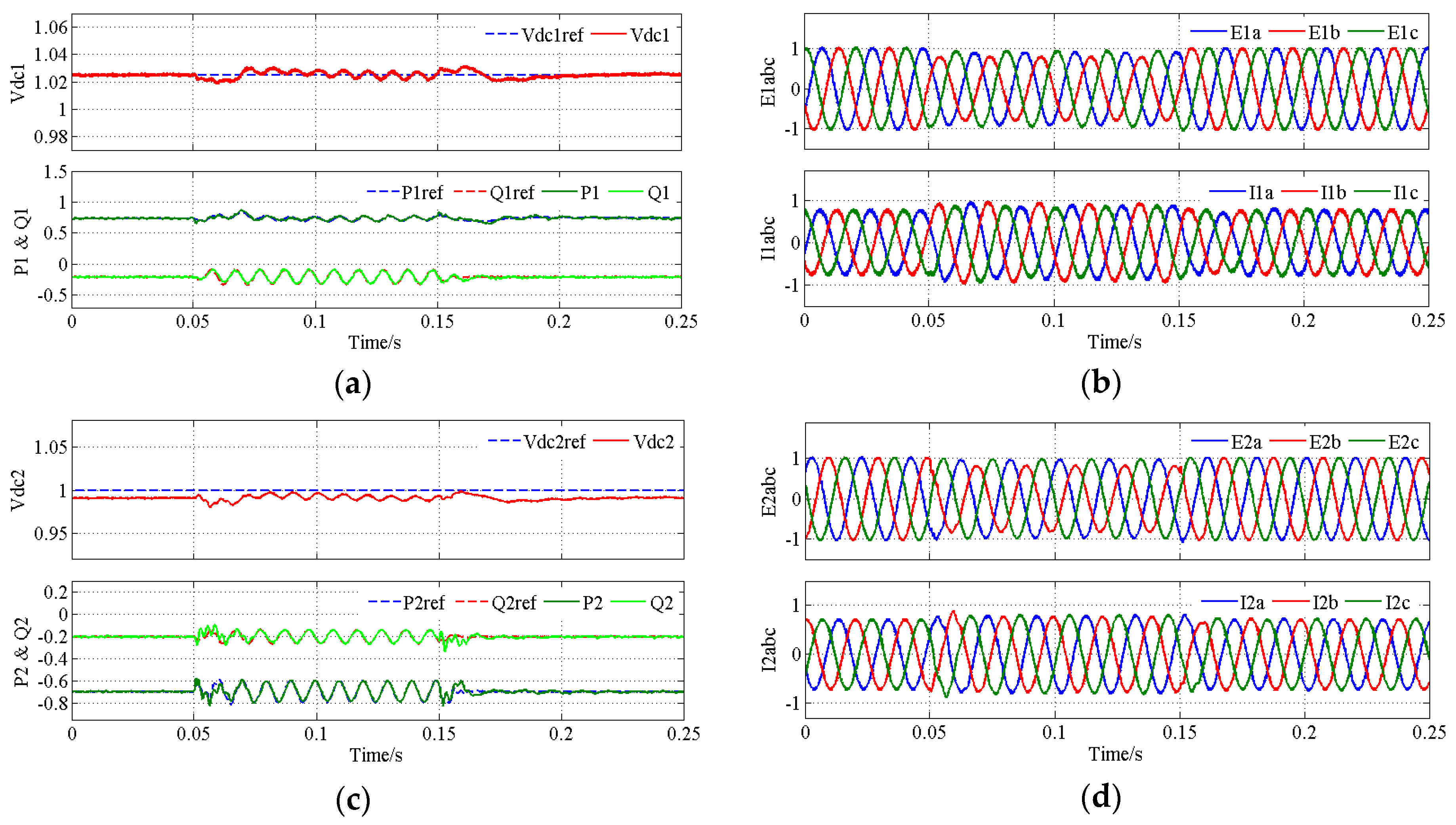
In Figure 7, the responses of CS1 and CS2 to sudden grid voltage unbalance disturbance, in the presence of parameter inaccuracy are shown. In this study, the grid voltage conditions for both CS are the same as those used for Figure 5, but (m, n) for CS1 and CS2 are set to (0.5, 1.5) and (1.2, 0.8), respectively. To investigate the robustness of the IRSMC DPC strategy, ac line inductance of CS1 and CS2 are set 20% smaller than the designed values. This poses more severe threats to system stability than when the inductance is larger than the designed value. In addition, we set the grid frequency for CS1 and CS2 to 49.5 Hz and 50.5 Hz, respectively.
We can observe from Figure 7 that the expected power control objectives are achieved with the IRSMC DPC strategy, in the presence of parameter inaccuracy and frequency deviation. Both power outputs track their references accurately, and the OAC of active and reactive power ripples can be controlled continuously. This enables the VSC-HVDC system to provide flexible power control functions according to actual operating conditions, which is a potential benefit for the performance of the system on both the ac and dc sides.
5. Conclusions
This paper proposes an integral plus resonant sliding mode direct power control (IRSMC DPC) strategy for VSC-HVDC systems, under unbalanced grid voltage conditions. The generalized power compensation method presented enables the VSC-HVDC system to provide flexible power control functions, so that the desired system performance on both the ac and dc sides can be obtained under different operating conditions. The adoption of sliding mode control ensures system robustness to parameter uncertainty and disturbance, within certain bounds. By designing a SMC-based power controller consisting of the proportional, integral and resonant control laws, accurate power control objectives for VSC-HVDC system under grid voltage unbalance can be achieved. Simulation results show that the proposed IRSMC DPC strategy can provide satisfactory performance of the system over a large range of operating conditions. In building the model and designing the control law, some practical factors such as imperfection of switching devices and time delays etc., that may affect significantly system performance have been considered. Nevertheless, in order to verify the effectiveness of the strategy in real-world systems, and put it into application, experiments are necessary, which will be studied in future works.
Acknowledgments
This work is supported by the National Key R&D Program of China (2016YFB0900500).
Author Contributions
Weipeng Yang conceived and performed the research; Jungang Li built the model; Hang Zhang designed parameters of the model; Guoqi Li designed the control law; Weipeng Yang and Aimin Zhang wrote the paper, Jianhua Wang revised the manuscript. All of the authors were involved in preparing this manuscript.
Conflicts of Interest
The authors declare no conflict of interest.
References
- Flourentzou, N.; Agelidis, V.G.; Demetriades, G.D. VSC-Based HVDC power transmission systems: An overview. IEEE Trans. Power Electron. 2009, 24, 592–602. [Google Scholar] [CrossRef]
- Xie, H.; Bie, Z.; Lin, Y.; Zheng, C. A hybrid reliability evaluation method for meshed VSC-HVDC grids. Energies 2017, 10, 895. [Google Scholar] [CrossRef]
- Wang, H.; Wang, Y.; Duan, G.; Hu, W.; Wang, W.; Chen, Z. An improved drop control method for multi-terminal VSC-HVDC converter stations. Energies 2017, 10, 843. [Google Scholar] [CrossRef]
- Zheng, H.; Jiang, D.; Xu, F.; Liang, Y. Optimum configuration for AC/DC converters of DC distribution network. Int. Trans. Electr. Energy Syst. 2015, 25, 2058–2070. [Google Scholar] [CrossRef]
- Yang, W.; Zhang, A.; Li, J.; Zhang, H.; Wang, J. Comparative analysis on different upgrading and reform schemes for 10 kV AC power distribution network. Autom. Electr. Power Syst. 2016, 40, 217–223. [Google Scholar] [CrossRef]
- Mousavizadeh, S.; Haghifam, M.R.; Shariatkhah, M.H. A new approach for load flow calculation in AC/DC distribution networks considering the control strategies of different converters. Int. Trans. Electr. Energy Syst. 2016, 26, 2479–2493. [Google Scholar] [CrossRef]
- Haruni, A.M.O.; Negnevitsky, M.; Haque, M.E.; Gargoom, A. A novel operation and control strategy for a standalone hybrid renewable power system. IEEE Trans. Sustain. Energy 2013, 4, 402–413. [Google Scholar] [CrossRef]
- Wang, G.; Ciobotaru, M.; Agelidis, V.G. Power smoothing of large solar PV plant using hybrid energy storage. IEEE Trans. Sustain. Energy 2014, 5, 834–842. [Google Scholar] [CrossRef]
- Song, Z.; Tian, Y.; Yan, Z.; Chen, Z. Direct power control for three-phase two-level voltage-source rectifiers based on extended-state observation. IEEE Trans. Ind. Electron. 2016, 63, 4593–4603. [Google Scholar] [CrossRef]
- Hu, J.B.; Shang, L.; He, Y.K.; Zhu, Z.Q. Direct active and reactive power regulation of grid-connected DC/AC converters using sliding mode control approach. IEEE Trans. Power Electron. 2011, 26, 210–222. [Google Scholar] [CrossRef]
- Yin, B.; Oruganti, R.; Panda, S.K.; Bhat, A.K.S. An output-power-control strategy for a three-phase PWM rectifier under unbalanced supply conditions. IEEE Trans. Ind. Electron. 2008, 55, 2140–2151. [Google Scholar] [CrossRef]
- Leon, A.E.; Mauricio, J.M.; Solsona, J.A.; Gomez-Exposito, A. Adaptive control strategy for VSC-based systems under unbalanced network conditions. IEEE Trans. Smart Grid 2010, 1, 311–319. [Google Scholar] [CrossRef]
- Wen, B.; Boroyevich, D.; Burgos, R.; Mattavelli, P.; Shen, Z. Analysis of D-Q small-signal impedance of grid-tied inverters. IEEE Trans. Power Electron. 2015, 31, 675–687. [Google Scholar] [CrossRef]
- Dong, D.; Wen, B.; Boroyevich, D.; Mattavelli, P. Analysis of phase-locked loop low-frequency stability in three phase grid connected power converters considering impedance interactions. IEEE Trans. Ind. Electron. 2016, 62, 310–321. [Google Scholar] [CrossRef]
- Shang, L.; Hu, J.B. Sliding-mode-based direct power control of grid-connected wind-turbine-driven doubly fed induction generators under unbalanced grid voltage conditions. IEEE Trans. Energy Convers. 2012, 27, 362–373. [Google Scholar] [CrossRef]
- Shang, L.; Sun, D.; Hu, J. Sliding-mode-based direct power control of grid-connected voltage-sourced inverters under unbalanced network conditions. IET Power Electron. 2011, 4, 570–579. [Google Scholar] [CrossRef]
- Sun, D.; Wang, X.; Nian, H.; Zhu, Z.Q. A sliding-mode direct power control strategy for DFIG under both balanced and unbalanced grid conditions using extended active power. IEEE Trans. Power Electron. 2017. [Google Scholar] [CrossRef]
- Wang, X.; Sun, D.; Zhu, Z.Q. Resonant based backstepping direct power control strategy for DFIG under both balanced and unbalanced grid conditions. IEEE Trans. Ind. Appl. 2017, 53, 4821–4830. [Google Scholar] [CrossRef]
- Nian, H.; Cheng, P.; Zhu, Z.Q. Coordinated direct power control of DFIG system without phase-locked loop under unbalanced grid voltage conditions. IEEE Trans. Power Electron. 2016, 31, 2905–2918. [Google Scholar] [CrossRef]
- Hu, J.; Zhu, J.; Dorrell, D.G. Predictive direct power control of doubly fed induction generators under unbalanced grid voltage conditions for power quality improvement. IEEE Trans. Sustain. Energy 2015, 6, 943–950. [Google Scholar] [CrossRef]
- Zhang, Y.; Qu, C. Model predictive direct power control of PWM rectifiers under unbalanced network conditions. IEEE Trans. Ind. Electron. 2015, 62, 4011–4022. [Google Scholar] [CrossRef]
- Hao, X.; Yang, X.; Liu, T.; Chen, W. A sliding-mode controller with multiresonant sliding surface for single-phase grid-connected VSI with an LCL filter. IEEE Trans. Power Electron. 2013, 28, 2259–2268. [Google Scholar] [CrossRef]
- Sun, D.; Wang, X.; Fang, Y. Backstepping direct power control without phase-locked loop of AC/DC converter under both balanced and unbalanced grid conditions. IET Power Electron. 2016, 9, 1614–1624. [Google Scholar] [CrossRef]
- Kulka, A. Sensorless Digital Control of Grid Connected Three Phase Converters for Renewable Sources. Ph.D. Thesis, Norwegian University of Science and Technology, Trondhein, Norway, 2009. [Google Scholar]
- Bobrowskarafal, M.; Rafal, K.; Jasinski, M.; Kazmierkowski, M. Grid synchronization and symmetrical components extraction with PLL algorithm for grid connected power electronic converters—A review. Bull. Pol. Acad. Sci. Tech. Sci. 2011, 59, 485–497. [Google Scholar] [CrossRef]
Figure 1.
Single-line diagram of the two-terminal voltage source converter high voltage direct current (VSC-HVDC) system studied.
Figure 1.
Single-line diagram of the two-terminal voltage source converter high voltage direct current (VSC-HVDC) system studied.
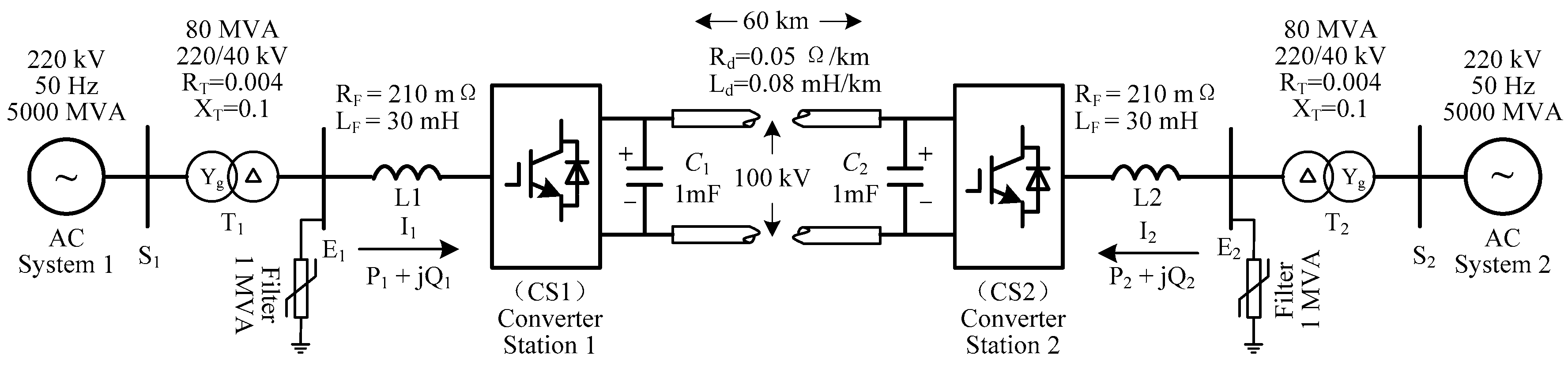
Figure 2.
Schematic of three-phase VSC for each converter station.
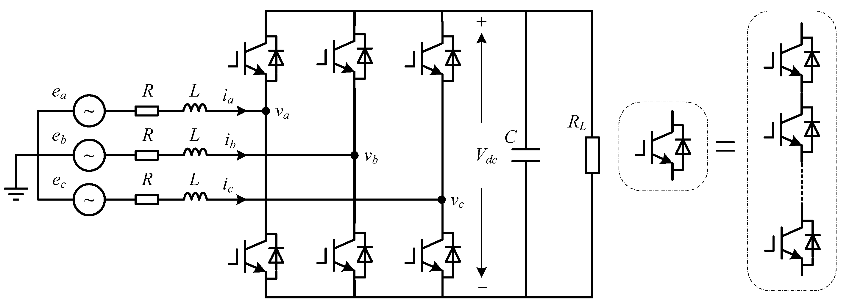
Figure 3.
Control structure of the proposed integral plus resonant sliding mode direct power control (IRSMC DPC) strategy.
Figure 3.
Control structure of the proposed integral plus resonant sliding mode direct power control (IRSMC DPC) strategy.
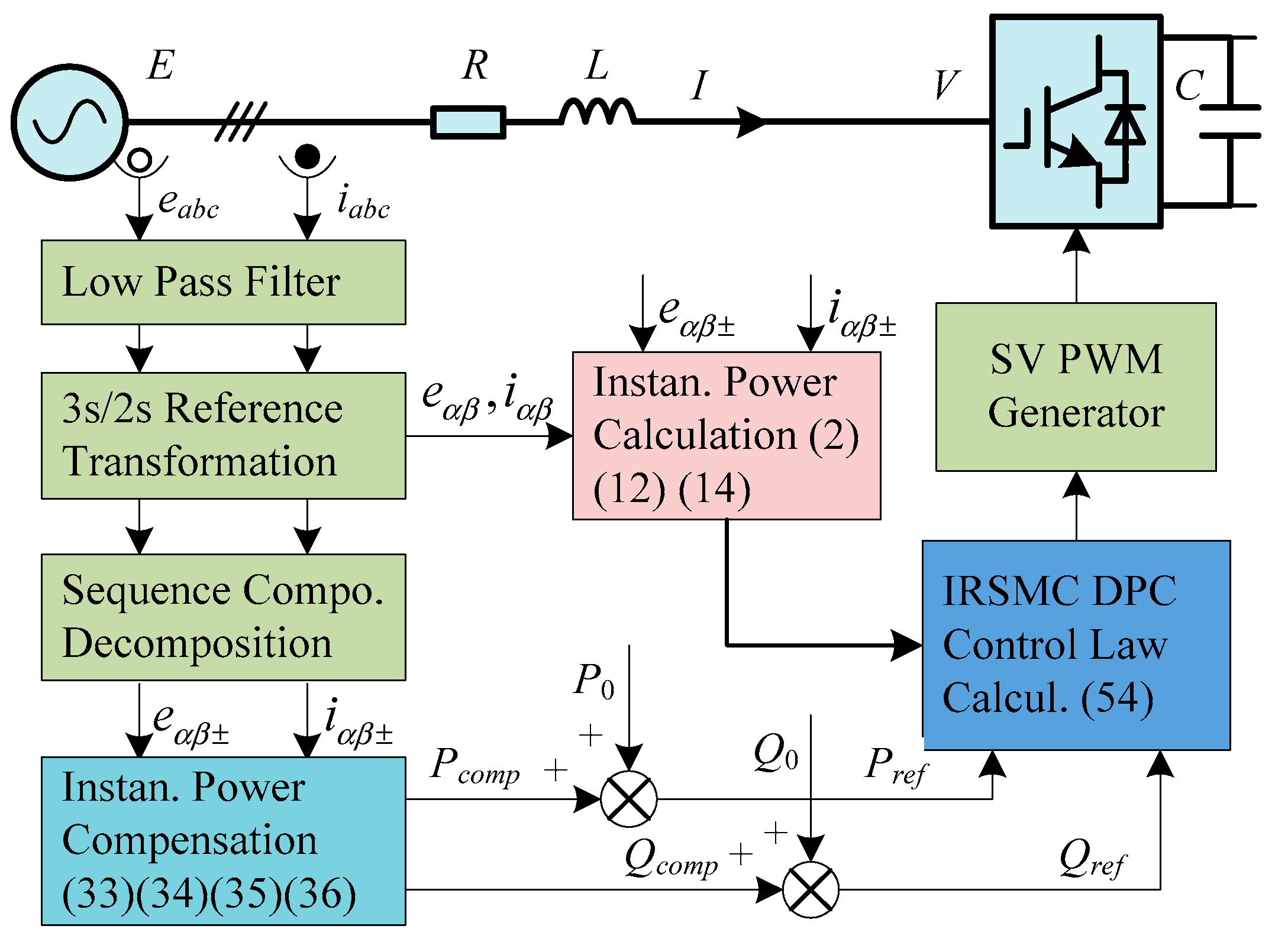
Figure 4.
Block diagram of sequence component extraction.
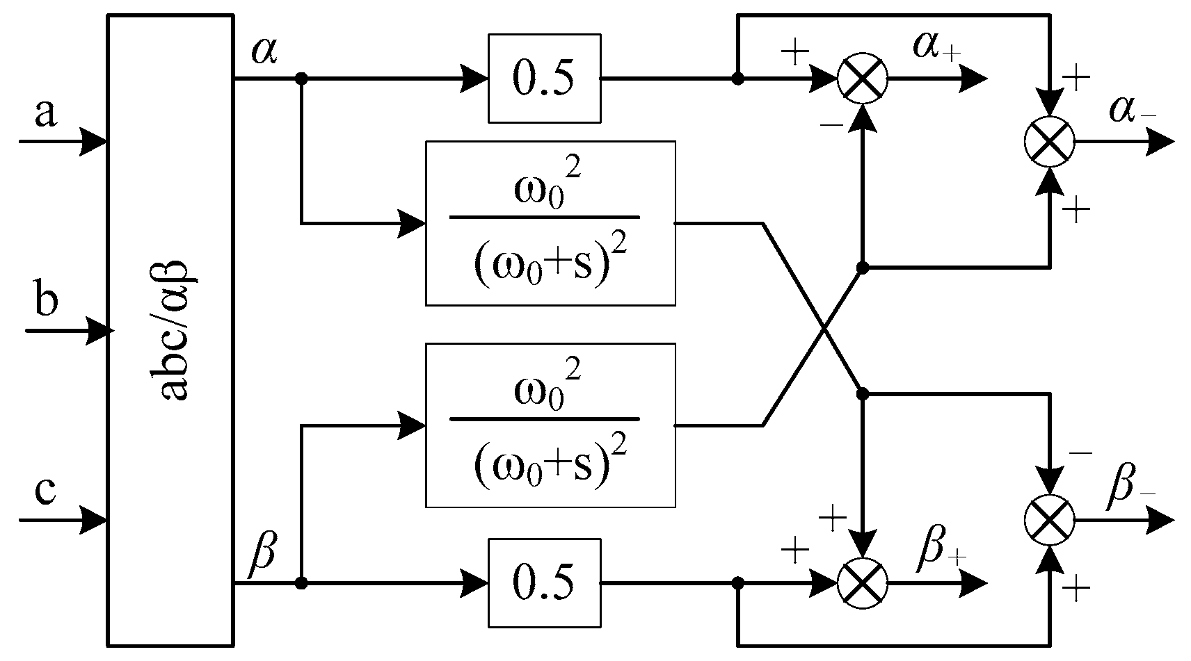
Figure 5.
System response to grid voltage unbalance disturbances. (a) dc bus voltage, active and reactive power for CS1 by IRSMC DPC controller; (b) grid voltage and ac current for CS1 by IRSMC DPC controller; (c) dc bus voltage, active and reactive power for CS2 by IRSMC DPC controller; (d) grid voltage and ac current for CS2 by IRSMC DPC controller; (e) dc bus voltage, active and reactive power for CS1 by RSMC DPC controller; (f) grid voltage and ac current for CS1 by RSMC DPC controller.
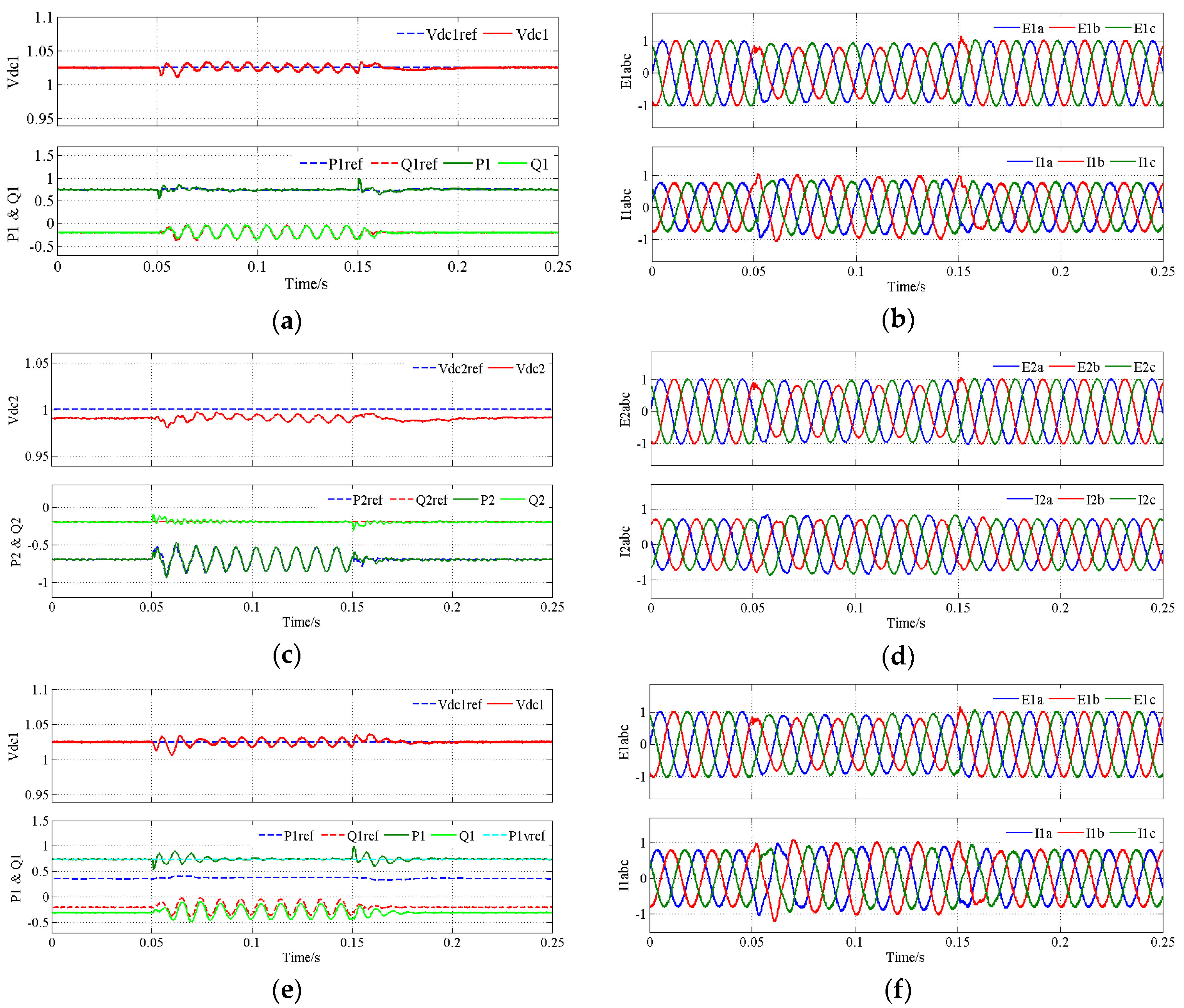
Figure 6.
System response to active power step changes under grid voltage unbalance. (a) dc bus voltage, active and reactive power for CS1 by IRSMC DPC controller; (b) grid voltage and ac current for CS1 by IRSMC DPC controller; (c) dc bus voltage, active and reactive power for CS2 by IRSMC DPC controller; (d) grid voltage and ac current for CS2 by IRSMC DPC controller; (e) dc bus voltage, active and reactive power for CS2 by ISMC DPC controller; (f) grid voltage and ac current for CS2 by ISMC DPC controller.
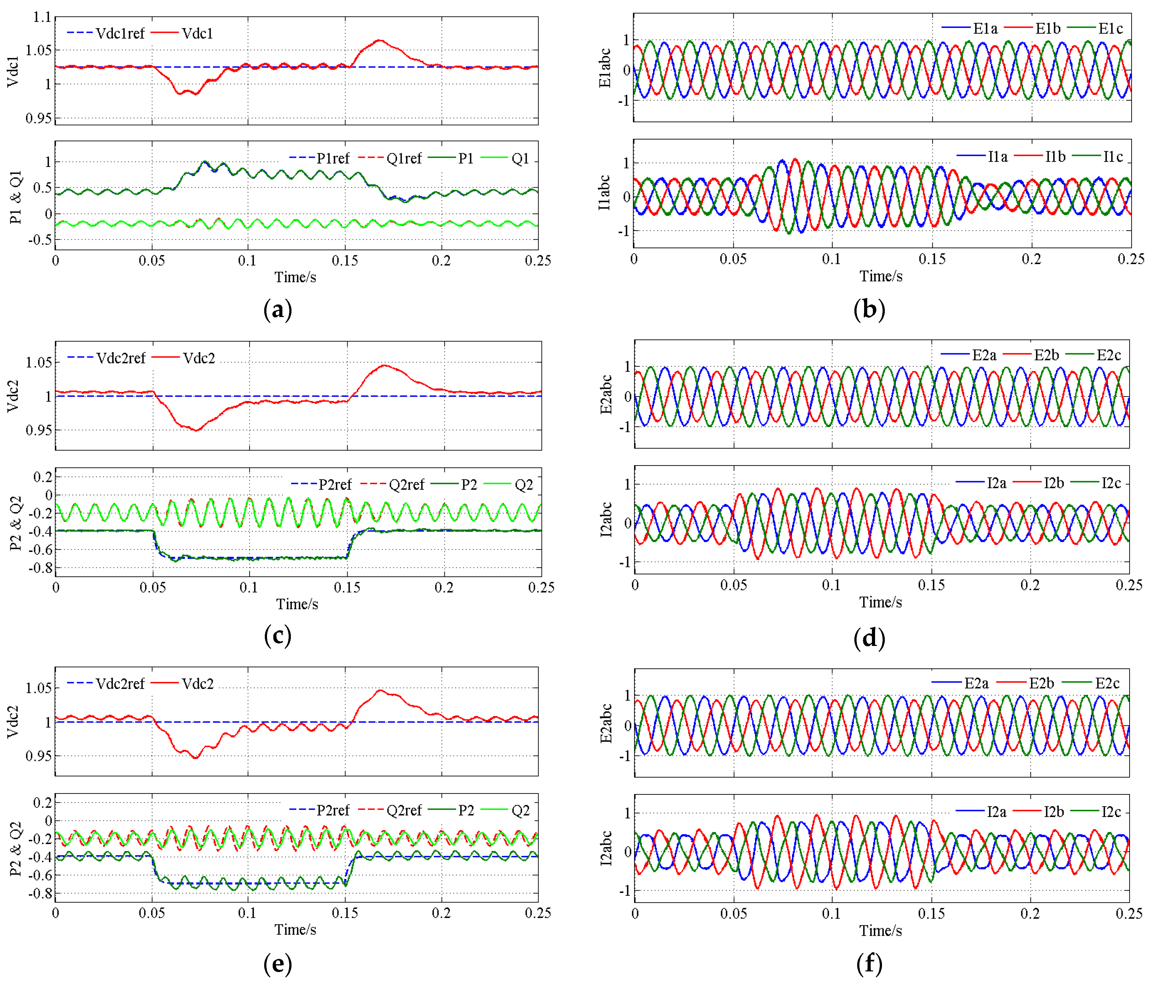
Figure 7.
System response to grid voltage unbalance disturbance in the presence of parameter inaccuracy and frequency deviation by the proposed IRSMC DPC controller. (a) dc bus voltage, active and reactive power for CS1; (b) grid voltage and ac current for CS1; (c) dc bus voltage, active and reactive power for CS2; (d) grid voltage and ac current for CS2.

Table 1.
Main Parameters of the IRSMC DPC Controller.
| Parameter | Value | Parameter | Value |
|---|---|---|---|
| KPI, KQI | 50 | KPR, KQR | 2.5 |
| KPS, KQS | 1200 | ωc | 10 |
Table 2.
Symbols used in the simulation results and their meanings.
| Symbol | Meaning |
|---|---|
| Vdc1, Vdc2 | Dc bus voltage on CS1 and CS2 side |
| E1abc, E2abc | Grid voltage on CS1 and CS2 side |
| I1abc, I2abc | Ac current on CS1 and CS2 side |
| P1, Q1, P2, Q2 | Active and reactive power at PCC of CS1 and CS2 |
| P1ref, Q1ref, P2ref, Q2ref | Active and reactive power references to respective power control loop for CS1 and CS2 |
© 2017 by the authors. Licensee MDPI, Basel, Switzerland. This article is an open access article distributed under the terms and conditions of the Creative Commons Attribution (CC BY) license (http://creativecommons.org/licenses/by/4.0/).
Share and Cite
MDPI and ACS Style
Yang, W.; Zhang, A.; Li, J.; Li, G.; Zhang, H.; Wang, J. Integral Plus Resonant Sliding Mode Direct Power Control for VSC-HVDC Systems under Unbalanced Grid Voltage Conditions. Energies 2017, 10, 1528. https://doi.org/10.3390/en10101528
AMA Style
Yang W, Zhang A, Li J, Li G, Zhang H, Wang J. Integral Plus Resonant Sliding Mode Direct Power Control for VSC-HVDC Systems under Unbalanced Grid Voltage Conditions. Energies. 2017; 10(10):1528. https://doi.org/10.3390/en10101528
Chicago/Turabian StyleYang, Weipeng, Aimin Zhang, Jungang Li, Guoqi Li, Hang Zhang, and Jianhua Wang. 2017. "Integral Plus Resonant Sliding Mode Direct Power Control for VSC-HVDC Systems under Unbalanced Grid Voltage Conditions" Energies 10, no. 10: 1528. https://doi.org/10.3390/en10101528
Note that from the first issue of 2016, this journal uses article numbers instead of page numbers. See further details here.