1. Introduction
The climate changes experienced in the last decades and the ever-increasing awareness of greenhouse gases are incentivizing the exploitation of renewable energy sources (RESes), in particular sun and wind, as alternatives to fossil fuels in electrical energy generation, as reported by the International Energy Agency (IEA) in Reference [
1]. Such RESes are employed not only in bulk generation facilities, but they are widely embedded in distribution networks. Especially at the low voltage (LV) level, several incentivizing policies have been applied in terms of economic facilitators (such as feed-in tariffs and net-metering), resulting in a wide installation of rooftop photovoltaic (PV) units in residential areas.
Nevertheless, PV generation and electricity consumption have different daily trends and their mismatch entails the need to export a significant part of the locally-generated energy to the grid. In addition, the same amount of energy is drawn for local consumption in other time periods [
2]. This practice causes inefficiency and raises several issues concerning the distribution network management (e.g., voltage regulation, congestion management, distribution power losses, etc.). At the same time, the unit price paid by the end-user for purchasing electricity is commonly higher than the unit income obtainable by injecting energy into the grid. Since a large reduction of net-metering advantages is expected in the near future, the maximization of the self-consumption rate of the generated energy is a key point to increase the economic potential of PV. In Reference [
3], storage units coupled with PV systems are analyzed in terms of profitability to make PV economically attractive even in the absence of regulatory support, taking into account the different components of costs and revenues.
Electrochemical battery energy storage systems (BESSes) are a promising solution for the maximization of customers’ self-consumption, since they are nowadays available on the market for residential use, and their cost is expected to significantly decrease thanks to the spread of several technologies integrating storage devices (e.g., electric vehicles).
The aim of today’s batteries, i.e., the self-consumption of the PV production, is achieved through the energy-on-demand function. In fact, if no communication systems with the distribution system operator (DSO) are available, different strategies to combine local generators and storage devices have been addressed. For instance, in Reference [
4], a control strategy is presented for a residential BESS able to maximize the self-consumption and to minimize the curtailment losses caused by feed-in thresholds without need of generation/load forecasts. Results show that the increase of self-consumption is desirable from a network management perspective, given the reduction in the curtailment losses. Furthermore, the authors point out that the aggregation of several local units is preferable in comparison with district storage. In Reference [
5], a comparison among a few battery discharge strategies for a grid connected building is presented, focusing on the self-consumption maximization, the time-shift function based on the predicted load, and the economic income. Neural networks are employed to set the sizing equations of the storage units, then the proposed discharge algorithms aim either at pursuing a network global optimum or the maximum user income. Analogously, in Reference [
6], the authors described the design of a lithium-ion storage system to increase the matching between generation and consumption in a residential zero-energy building, resulting in a reduction of the power exchange with the grid by more than 75% and a decrease in the energy bill of 87%.
Nevertheless, several smart pricing models have been investigated. It seems to be an opportunity for DSOs to involve active end-users (integrating local generation and BESSes) in the electric system management, e.g., in the network power flow reduction [
7,
8] or in the voltage regulation [
9]. In Reference [
7], active demand is coupled with storage, improving the self-consumption in order to study the relation between annual energy flows and the storage size. Regarding innovation in the energy market, an alternative pricing strategy is proposed to incentivize the energy independency of end-users from the grid in Reference [
8], whereas a network controller based on local price signals is presented in Reference [
9]. Many research works are based on the demand-side management (DSM) approach, in which customers are economically remunerated for adjusting two-way power flow at their point of delivery (PoD), either in terms of absorption or injection, to contribute to congestion reduction when the distribution network is under stress. In References [
10,
11], some of the most common DSM approaches available in literature are surveyed to compare individual vs. cooperative management, deterministic vs. stochastic methods, and day-ahead vs. real-time operation. In Reference [
12], an optimized home energy management system facilitating the RESes exploitation and the participation to DSM activities is implemented considering an optimized scheduling of the home appliances according with a varying energy price. The simultaneous optimization of both electric and gas distribution networks through DSM is investigated in Reference [
13], showing a reduction of the energy bill by 20%. Generally, the DSM is achieved through both the optimized management of storage units (with scheduling procedures and real-time corrections [
14]) and the classification of loads depending on their supply priority [
15]. In Reference [
14], the energy production, including the BESS management, is scheduled one day ahead, following which a real-time control scheme tracks the expected profile to minimize the power curtailment. A fast-balancing service for the power system is obtained through the management of controllable loads (either passive or active) in Reference [
15]. The end-user satisfaction (i.e., the reduction of the inconvenience due to the scheduled loads operation) is additionally considered in the DSM scheme proposed in Reference [
16], elaborating an optimal compromise between user-budget and satisfaction, whereas these factors are used in a multi-objective optimization in Reference [
17] to reduce the energy exchange with the grid and, eventually, the bill cost.
At the same time, a further income can be obtained by allowing distributed resources to participate to the ancillary services market, such as the network voltage regulation and the containment of voltage unbalances. In Reference [
18], a study about the optimal sizing, siting, and managing of storage units is presented to investigate their impact on the ancillary services provision. A voltage unbalance mitigation strategy is proposed for three-phase inverters in Reference [
19], aiming at the compensation of negative and zero sequence voltage components in LV systems, whereas the same approach is extended to RESes connected to medium voltage (MV) networks in Reference [
20]. The exploitation of BESSes has been proposed for power quality improvement. Control schemes for reducing the harmonic distortion, both referring to a single customer equipped with a PV plant [
21] and aggregating the storage contributions in a smart community [
22], are discussed in the literature. The use of RESes in the dynamic grid support is highlighted in Reference [
23] according to the most recent standard requirements, whereas the BESS role in stand-alone systems with wind generation is investigated in Reference [
24]. Storage units are included in the management strategy of an islanded network in Reference [
25]. Nevertheless, the increasing diffusion of storage systems, although compliant with European standards and national grid codes (e.g., [
26,
27]), may lead to safety issues. In the case of faults, portions of the LV network may be maintained energized by dispersed generators and BESSes, since their stabilizing contributions mask voltage and frequency perturbations, resulting in the failure of present passive anti-islanding protections [
28,
29].
An increased attention on storage systems has been recorded in the last couple of years. New norms and standards currently regulate the procedures/rules for installing and operating BESSes, both in LV distribution systems [
26,
27] and in MV networks (e.g., [
30,
31]). The main drivers of this possible market evolution are linked to:
Avoiding the local emission of greenhouse gases (making use of full-electric appliances and decarbonized generation sources);
Increasing self-consumption;
Reducing the influence of electricity market variations on the customer’s bill by limiting the amount of purchased energy; and
Necessity of avoiding long power outages in the case of serious network events (very frequent in many countries) and supplying energy if the network is not yet present (rural electrification).
The BESS installation is usually considered a private investment and its economic standpoint has to be suitably accounted. This issue is discussed in several research papers. For instance, in Reference [
32], it is demonstrated that a storage system may not be profitable for the customer in comparison to the case without BESS. Differently, the BESS investment is considered an interesting perspective in Reference [
33], where the storage management for economically optimizing the BESS installation is addressed, taking into account the non-normal distribution of local generation and demand. Nevertheless, it should be considered that: (i) incentivizing policies are currently applied in several countries (e.g., a 50% discount in the form of tax reduction, refunded in 10 years, in the Italian context [
8]); (ii) the BESS market is rapidly evolving, i.e., a significant drop in battery prices is expected as a consequence of the market volume increase; and (iii) the electricity pricing structure, e.g., energy constant price (ECP), time of use (TOU), or real-time pricing (RTP), significantly impacts on the end-user bill. In Reference [
34], a general method for the components design of a PV-BESS integrated system according to a comprehensive techno-economic analysis is presented, taking into account the state-of-the-art. A cost analysis is reported in Reference [
35], focusing on the residential context and considering several parameters, such as battery end-of-life criterion, battery aging behavior, electricity price, and investment costs. Outcomes of this work suggest that the ‘battery parity’ is possible in the next few years.
An integrated design is required for modern PV-BESS systems, which have the role of suitably managing the power flow of the active customer, e.g., (i) to optimize the generation, i.e., performing the maximum power point (MPP) tracking for maximizing the PV power output; (ii) to interact with the batteries, which are suggested to be locally sited to minimize the cable length; (iii) to supply the end-user internal loads, eventually classifying them as primary and secondary appliances in the case of an intentional islanded operation; and (iv) to exchange power surplus and deficit with the public network, eventually according to market signal or ancillary services requests from the DSO in the near future. Active end-users equipped with modern PV-BESS integrated systems could also aggregate their behaviors, according to each operating state and local available resources, to interact with the power system as an equivalent subject, able to both operate in the energy market and provide the better technical-economic results to all its participants. It should be remembered that storage systems presently available on the market are required to be compliant with the test protocols described by local grid codes, e.g., the connection standard CEI 0-21 for active customers interfaced with Italian LV public networks [
27].
Currently, the majority of the commercially-available storage solutions to integrate PV systems in the residential sector consist of lithium-ion (Li-ion) batteries. Nevertheless, several technologies with different properties are worth investigating. For instance, in Reference [
36], lead-acid (Pb-acid), sodium-nickel chloride (NaNiCl
2), Li-ion, and nickel/cadmium (NiCd) batteries are introduced, whereas a comparison based on energy, environmental, technical, and economic criteria is reported in Reference [
37]. The suitability of these technologies in the residential context is addressed in Reference [
38].
In this paper, the NaNiCl
2 battery, also known as ZEBRA in the past (acronym of Zero Emission Battery Research Activities), is considered. The high lifetime, the high peak power capacity, and reduced long-term specific cost are promising aspects, as well as the ongoing research progress. On the other hand, this technology makes use of a dedicated electrochemistry, with beta alumina as a sodium ion conducting solid electrolyte. As a consequence, the optimal performances are obtained in the temperature range 260/320 °C, i.e., 533/593 K [
39,
40]. Thus, the battery temperature has to be regulated through an internal heater and an external fan (the latter only in case a heavy discharging power is required, e.g., when the battery is used in electrical vehicles, during the acceleration phase or while climbing uphill).
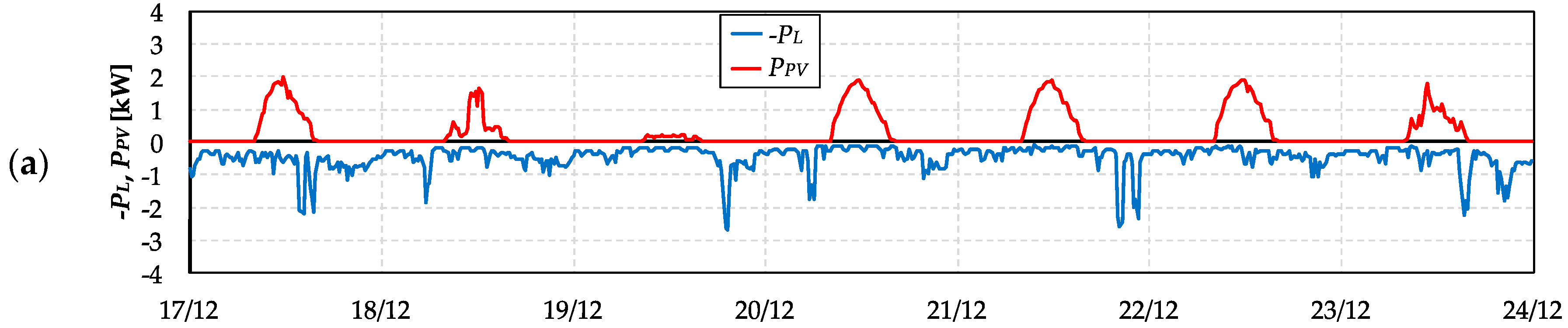
The evolution of NaNiCl2 technology is detailed with a specific focus on the residential level, where the distributed generation (DG) is mainly photovoltaic. A simplified thermoelectric analysis characterizing the management issues related to this battery and estimating the yearly economic profitability (including heating costs) is presented in this paper. Results are evaluated starting from real profiles of both load consumption and solar radiation, obtained with a quarter-hour time resolution through field measurements on an annual period. The presently-applied electricity tariffs (as defined by the Italian energy authority with reference to the third quarter of 2017) are considered.
In the following,
Section 2 describes the main NaNiCl
2 battery advantages and recent developments in residential applications, whereas
Section 3 details the presented procedure for the simplified technical-economic characterization of an active end-user equipped with a PV plant and a NaNiCl
2-based BESS. In
Section 4, the present policies for pricing both purchased and sold electricity amounts are detailed.
Section 5 reports the main results obtained from the developed algorithm and
Section 6 summarizes the main conclusions.
Table 1 reports all the acronyms used in the paper.
2. NaNiCl2 Battery Pros for Residential Applications
The operating principle, performance, charging/discharging curves, production process, and possible applications of sodium-nickel chloride batteries are deeply described in References [
39,
40]. Several successful applications of this technology in electric mobility, both considering full-electric vehicles and hybrid solutions (in which the battery is used to optimize the overall efficiency of vehicles equipped with fossil-fuel motors) are detailed in the literature. For example, in Reference [
41], preliminary results obtained in the experimental field test of the Bologna’s bus fleet are presented and discussed. ZEBRA batteries are also considered for the electrification of urban commercial vehicles (e.g., vans for city logistics) in the laboratory test bench described in Reference [
42]. A research study [
43] investigates the advantages of coupling the NaNiCl
2 battery with a supercapacitor to increase the dynamic and energetic performances, i.e., the power exchange between the electric drive and the overall storage system during both the acceleration phase and the regenerative electric braking. In Reference [
44], according to the vehicle-to-grid (V2G) approach, the authors analyze the positive interactions between electrical vehicles and the power grid, comparing a wide range of possible storage technologies.
The features of this technology can prove very interesting in critical backup power applications (as an uninterruptible power supply). A stationary application in South California demonstrates that ZEBRA battery performances are independent of ambient temperature, self-discharge is negligible, and the heater consumption for the internal temperature regulation is low and slightly influenced by external conditions [
45]. Finally, marine, submarine, and train applications are under study.
A few studies regarding the installation of ZEBRA batteries at the customer level make use of simplified battery models. In References [
46,
47], batteries are considered for supplying demand response (DR) and tariff arbitrage at the residential level in the United States context, whereas they are used in combination with a medium-sized PV plant to increase the self-sufficiency of a multi-apartment building in Sweden in Reference [
48]. Unfortunately, this study makes use of hourly average profiles in the north of Europe and the thermal behavior of the sodium-nickel chloride batteries is not modeled in detail.
In this paper, the use of the NaNiCl2 battery technology in the domestic context is considered. In particular, the integration with a local PV unit for increasing the customer self-consumption and to indirectly reduce the end-user impact on the network management (since reducing the exchanged power with the network generally means reduced voltage regulation problems and lower distribution losses) is deeply investigated by adopting a simplified thermoelectric model of the sodium-nickel chloride battery. This technology, covering a typical consumption range of some hours, shows some specific and useful performances for this specific usage:
Highly safe operation, demonstrated by the achievement of some important certifications (according to standards UL1973 “Standard for batteries for use in light electric rail applications and stationary applications”, network equipment building standard NEBS level 3, and CE, which is the manufacturer’s declaration of product’s conformity with health, safety, and environmental protection standards for products sold within the European economic area). Positive results to some abuse tests, such as crash tests (i.e., forcing an operative battery against a pole with speed 50 km/h), vibration test, over-charge test, over-discharge test, short-circuit operation, submersion test, and fire exposure, are demonstrated [
49]. In detail, since the battery is compliant with requirements for the vehicle use, it passes all the mentioned tests thanks to its four-barrier safety concept: barrier by the chemistry, barrier by the cell case, barrier by the thermal enclosure and barrier by the battery controller [
40];
Zero ambient emission, i.e., the storage system can be installed in a sealed environment;
No ancillary equipment needed (e.g., air conditioners), making easier the installation;
Full recyclability, without extra costs for the end-users thanks to a well-set recycling process, which is certificated and cost effective [
40];
Maintenance-free design;
Wide operating temperature range without any performance de-rating (environmental temperature constraints −40/+60 °C, i.e., 233/333 K, derive exclusively from the power electronic admitted conditions), suitable for all typical location within building technical room;
Battery partial availability in case of single cell outage to ensure anytime, as much as possible, the high level of performance. In detail, in the case the beta alumina ceramic separator breaks, a chemical reaction producing aluminum and common kitchen salt (NaCl) starts, so the aluminum shorts the current path between plus and minus and the cell resistance is suitably reduced [
40]; and
Long calendar life (15 years) and cycle life (at least 4500 cycles @ 80% depth of discharge, DoD).
Many products based on Lead-acid or lithium-ion batteries available on the market do not show the same versatile functionalities. On the other hand, the sodium technology requires energy absorption to compensate for thermal dissipation to the environment. This issue involves to suitably design both the storage system rated energy and the BESS architecture to avoid long stand-by periods, since the sodium-based technologies provide the best performances if the battery is kept constantly in operation, as better discussed and modeled in the following sections.
The battery design chosen for the residential product is based on a 48 V module. A dedicated firmware has been developed to optimally match the specific residential requirements, such as:
Real-time current reversibility (no delay in state transition from discharge to charge and vice versa);
Specific algorithm to allow an optimized battery heater management even in case of reduced RES generation and off grid operation;
Suitable ModBus registers to allow a flexible remote monitoring;
Dedicated warnings to allow a better integration at system level with electronic converters; and
Modular design in order to allow further system capacity expansions.
In the BESS, a human-machine interface is recommended for the purpose of allowing the end-user to operate in front of the system, although apps for mobile devices are available to simplify the monitoring and the interaction with the overall system. The customer choice could range between different operative modes, such as: (i) on-grid (the battery is used to maximize the end-user self-consumption); (ii) off-grid, with automatic commutation between the grid-connected operation and the islanded condition according to local frequency/voltage measures; (iii) owned-grid (typical of rural areas not supplied by public networks, where some units could create a local micro-grid as a first electrification solution); and (iv) bypass mode (the storage system is excluded for whatever reason). In general, all the battery functions, set parameters, and local measures could be available remotely if a web server is connected to the system, for the purposes of data logging and customer support.
The NaNiCl
2 storage technology is continuing its evolution with the aim of both preserving the technology peculiarities and reducing the required operating temperature. For example, in Reference [
50], the operation of an improved ZEBRA battery operating at 175 °C is investigated to lower heating costs. Furthermore, in Reference [
51], the authors propose the improvement of the NaNiCl
2 cell cycle performance through the encapsulation of Ni particles with a Ni
3S
2 layer, whereas in Reference [
52], the thermal integration of the NaNiCl
2 battery with a solid oxide fuel cell prime mover is introduced to increase the overall efficiency in a residential building application.
3. BESS Operation Model
In this section, the algorithm characterizing the end-user operation is detailed. The procedure describes the operation of an active end-user, equipped with a PV generator and a storage system. However, the same results referred to the passive scenario or considering the sole PV unit are obtainable by nullifying the rated sizes of the PV unit and/or the BESS. The entire procedure has been implemented in Matlab® simulation software, version R2015b (MathWorks, Natick, MA, USA).
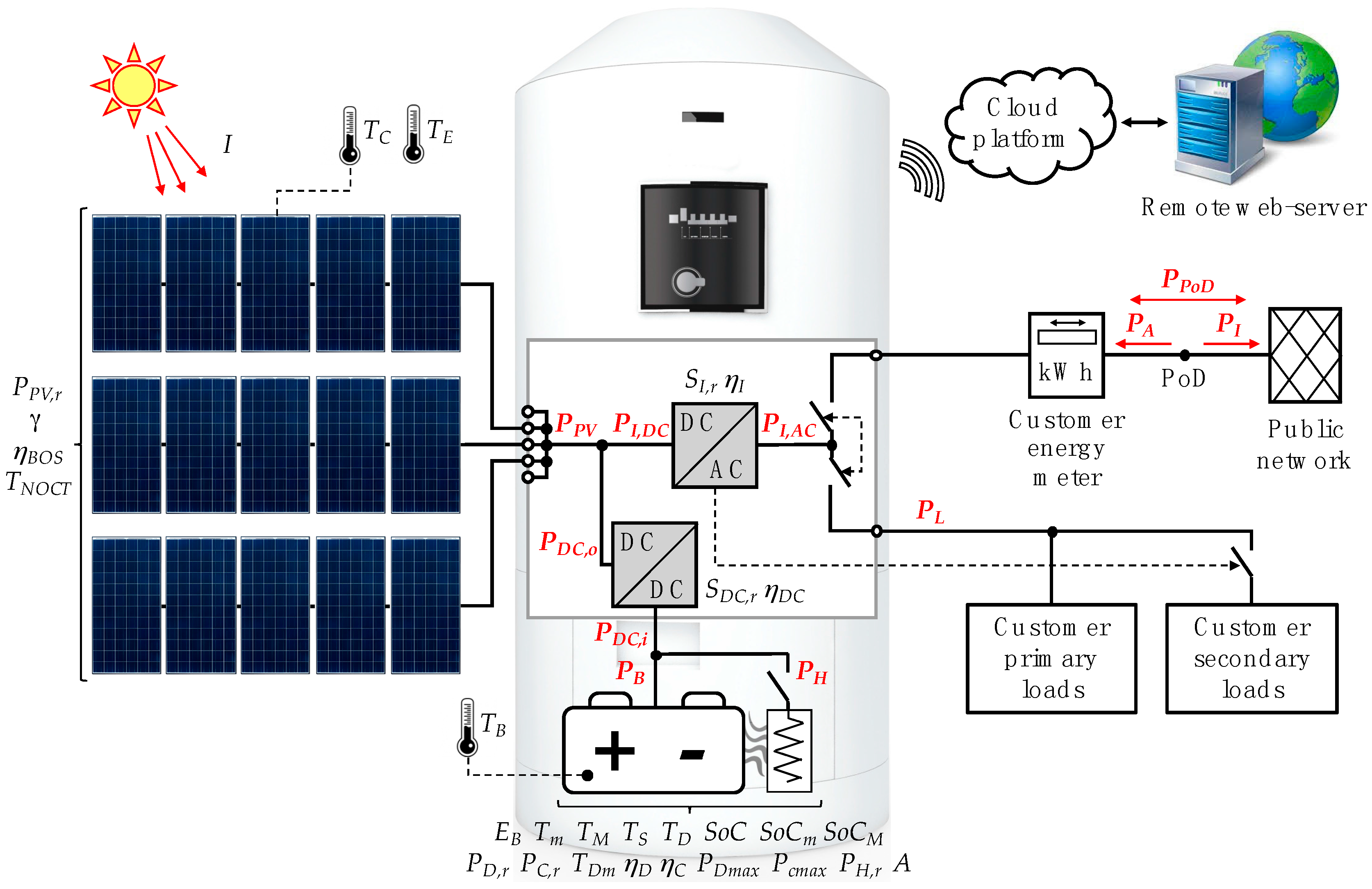
Since the PV generation is concentrated in the central hours of the day, whereas during working days the load consumption is higher in the morning and especially in the evening (e.g., considering a household owned by a couple of employees), the BESS is considered connected on the DC side of the main inverter, as depicted in
Figure 1. In this way, the diurnal PV surplus is directly storable in the batteries, without requiring a double DC/AC conversion, impacting system losses. Obviously, it should be considered that PV panels are representable as current sources (with imposed current depending on the incident solar radiation) and their MPP is obtained by imposing variable voltage at their ends depending on environmental conditions (i.e., solar radiation and air temperature affecting the PV cell temperature). On the other hand, the battery no-load voltage strongly depends on the internal state of charge (SoC), whereas the operating voltage is influenced by the charging/discharging current, as a result of Ohm’s law considering the batteries’ equivalent internal resistance. As a consequence, the main DC/AC converter is equipped with the MPP tracking function, whereas a DC/DC converter is introduced to suitably couple the BESS to the DC bus where PV panels are connected.
Figure 1 also reports the parameters introduced in the procedure described below. For the sake of clarity, they are grouped close to the physical elements they refer to, whereas their meaning is described in the following explanation of the developed algorithm. Power flows are reported with bold red font. All the variables and parameters are listed in
Table 2, with indications of the mathematical expressions in which they first appear.
3.1. PV Unit
At the time instant
t, the PV unit makes the power
PPV(
t) available on the DC bus, evaluated as in Equation (1), where
I(
t) (W/m
2) is the mean solar irradiance on the PV surface in the
t-th elementary time interval ∆
t (s),
ISTC is the same parameter as in the standard test conditions (STCs, solar irradiance 1000 W/m
2, cell temperature 25 °C, and solar spectrum AM 1.5), and
PPV,r (W) is the PV unit rated power.
Remembering that the rated characteristics of PV panels refer to STCs, the thermal losses in the case where the PV cell temperature differs from the standard value (25 °C) are represented as equivalent efficiency
ηT(
t) (dimensionless) defined as in Equation (2), where
γ < 0 (1/°C) is the thermal losses coefficient, commonly made available in the PV panel datasheet,
TC(
t) is the PV cell temperature at the time instant
t, and
TSTC is 25 °C. All the other losses affecting the PV generation up to the DC stage of the AC/DC converter, generally named as balance of system (BoS) losses (e.g., mismatching, pollution, reflection, ohmic losses on DC cables, etc.), are grouped in the equivalent efficiency
ηBOS (dimensionless):
In the case where
TC(
t) is not available from field measurements, it could be estimated as in Equation (3), considering the corresponding environmental temperature
TE(
t) and the PV panel nominal operating cell temperature
TNOCT (°C), directly dependent on the PV technology and usually reported in the PV panels datasheets.
3.2. End-User Operation without BESS
Without a BESS, the inverter converts the entire PV production to the AC bus, i.e., the power flow
PI,DC(
t) is equal to
PPV(
t). The DC/AC conversion efficiency is obtained from PV inverter datasheets. Weighted values are usually available, e.g., the European efficiency and the California Energy Commission efficiency, which provide differently weighted converter efficiencies at several loadings. Nevertheless, aiming at better representing the power converter operation and losses, the procedure supposes to know the inverter efficiency curve as a series of
i-th couples
p(
i) −
ηINV(
i), where
p(
i) are several machine loading rates and
ηINV(
i) are the corresponding conversion efficiencies. Thus, the considered converter efficiency
ηI(
t) depending on the effective loading
PI,DC(
t)/
SI,r is linearly interpolated as in Equation (4):
The end-user’s loads absorb the power
PL(
t) at the time instant
t, thus, in the case where the PV generation overcomes the local consumption, the PV surplus is injected into the grid. Considering the sole PV unit, the power exchanged with the network at the PoD
PPoD(
t) is, thus, computed with Equation (5) and the result is positive in the case of power exported to the public network (generator convention). The injected power flow
PI(
t) and the absorbed power flow
PA(
t) are defined as in Equations (6) and (7), respectively:
In a long-term analysis with time duration
T (where
T is usually assumed to be equal to one year to suitably consider both the load and the generation seasonal variations), the end-user injects into the network the energy amount
EI and absorbs from the distribution system the energy amount
EA, defined as in Equations (8) and (9), respectively. These parameters will be used for the economic comparison between different scenarios, according to the adopted schemes for pricing purchased and sold energies (detailed in the following):
3.3. BESS Model
In this procedure, the BESS is considered an end-user’s investment and no local ancillary service markets are established. The storage unit is managed with the aim of optimizing the final customer’s self-consumption and its economic profitability. Consequently, the BESS is charged in the case where the solar availability surpasses the local load consumption, and then it is discharged to reduce the amount of energy purchased from the public network when the generation is insufficient or absent.
The developed BESS model takes into account the peculiarities of the NaNiCl
2 technology, focused on the management of its internal temperature
TB(
t), which is required to be maintained in the admitted range (
Tm/
TM) (°C). In particular, the upper temperature threshold is one of the constraints during the discharging phase, considering that
TB(
t) significantly increases in the case of fast discharges [
42]. Different from use in electrical vehicles, and considering real domestic load trends, NaNiCl
2 batteries for stationary applications are not equipped with cooling fans to improve the thermal insulation of the battery, i.e., to reduce the heater consumption in order to maintain the internal temperature
TB in the admitted range. Thus, the constraint
TM could limit the discharging power, as detailed in the following.
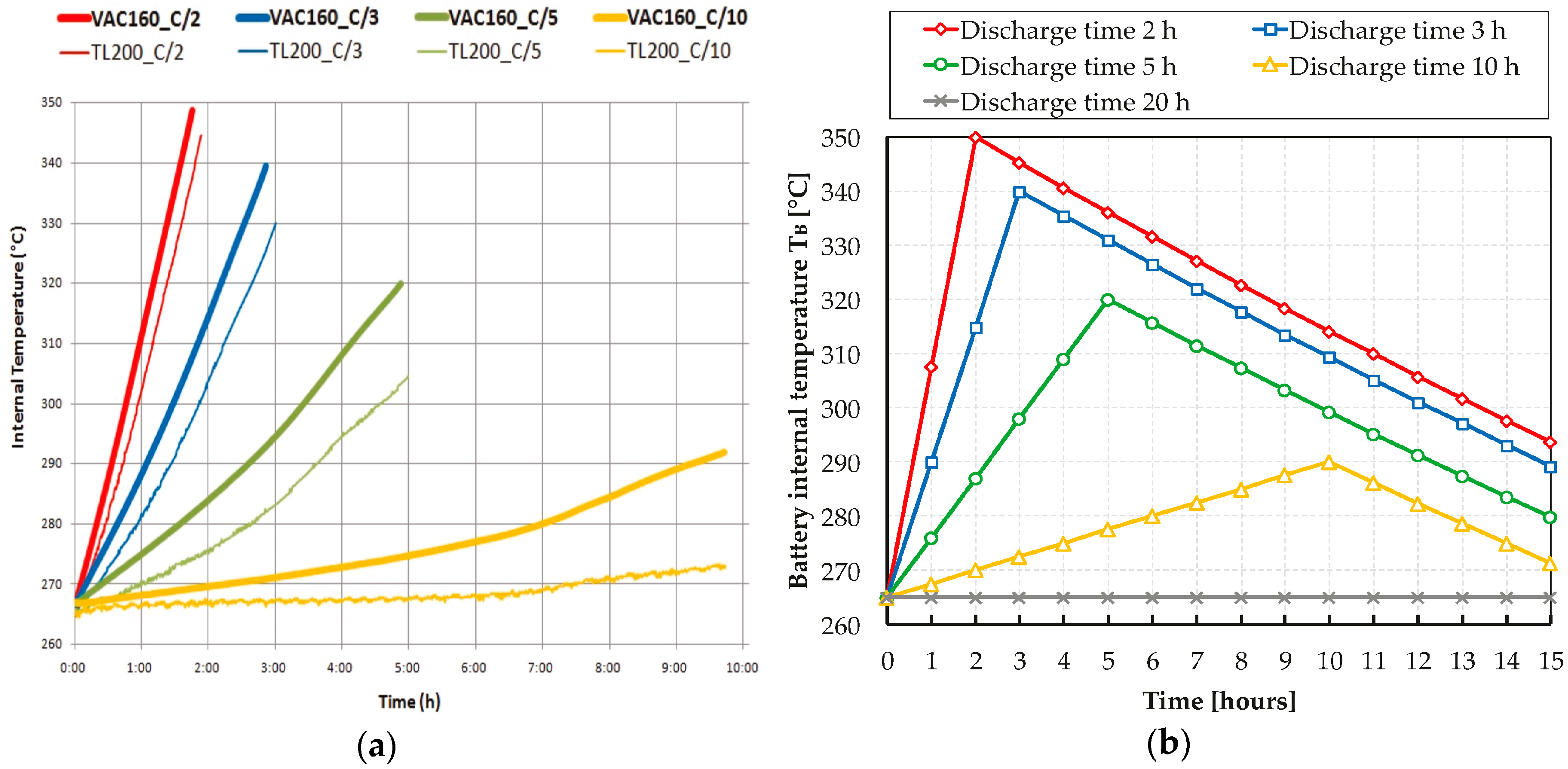
Figure 2a represents field measurements collected by means of laboratory tests to characterize the temperature behavior, depending on the considered discharging regime: the battery (suitable for residential applications in terms of storable energy, rated voltages, and sizes) is completely discharged with different time durations, obtaining consequent increases in the internal temperature.
After the complete discharge of the battery, it is left in the stand-by condition, which results in the battery cooling, represented through the temperature decrease
TD(
t) (°C) in the time interval ∆
t, as evaluated by Equation (10). In the model,
TD(
t) depends on the internal temperature
TB(
t) in comparison with the standard environmental temperature of 20 °C, whereas
TS (°C/h) is the hourly reduction in the internal temperature when it starts from 300 °C.
Figure 2b reports the equivalent representation adopted in this paper, as summarized in
Table 3. It is important to note that the model is very accurate, since only negligible errors are introduced in characterizing the thermal management of the battery. Intermediate discharging conditions are modeled by linearizing the behavior between adjacent discharging trends, similar to Equation (4).
Through this temperature characterization, the minimum admitted discharging time duration
TDm(
t) (h) is computed by knowing the battery internal temperature
TB(
t) and the maximum admitted threshold
TM. Consequently, the maximum admitted discharging power
PDmax(
t) at the
t-th time instant is obtained as the most binding among several operational constraints, synthetically represented in Equation (11). The parameter
PD,r is the BESS rated power in the discharging phase. The second constraint is related to the internal SoC at the
t-th time interval
SoC(
t), which cannot surpass the admitted thresholds
SoCm (dimensionless) and
SoCM (dimensionless) at the end of the time interval ∆
t, whereas
ηD (dimensionless) is the discharging efficiency and
EB (kWh) is the storage system rated energy. The DC/DC converter rated power is called
SDC,r (kVA).
Similarly, taking into account that the charging phase does not increment the battery internal temperature, the maximum admitted charging power
PCmax(
t) is can be evaluated by using Equation (12), where
PC,r is the BESS rated power in the charging phase and
ηC (dimensionless) is the charging efficiency:
To maximize the self-consumption of the PV generation, the output of the DC/AC converter should be equal to the customer’s loads overall consumption, as for the constraint of Equation (13). This means that the desired power on the DC side of the DC/AC converter
can be evaluated by Equation (14). In this case, for the purpose of simplicity, which means avoiding iterative computations, the loading rate of the DC/AC converter, required to estimate the static machine efficiency, is evaluated considering the desired output power
, instead of
as previously described in Equation (4). However, it should be noted that this simplification has negligible consequences on the overall computation, since the DC/AC converter efficiency is very high in a wide spectrum of loading rates and stand-by losses are limited to few Watts or less:
Considering the PV generator contribution, the desired power flow on the BESS DC/DC converter, at both the output port
and the input port
, are computed as in Equations (15) and (16), respectively. The DC/DC converter efficiency
ηDC(
t) is characterized by Equation (4), considering the static converter estimated loading rate equal to
/
SDC,r:
During the charging phases, the stand-by condition (e.g., when the batteries are no longer able to supply the end-user’s load since the minimum admitted SoC has been reached) or in the case of very weak discharging (as previously reported in
Table 3), if the battery internal temperature decreases close to the lower admitted threshold
Tm, an additional heating resistance has to be switched on. This regulates the internal temperature in the permitted range, avoiding a dangerous over-cooling, i.e., to compensate the thermal losses with the external environment. When the heater is switched on, its power absorption
PH(
t), supplied by the battery bus, has to be considered. The heater absorption
PH(
t) is lightly correlated with both the internal temperature and the environmental conditions. Assuming a reference environmental temperature of 20 °C,
PH(
t) is estimable through Equation (17), where
PH,r (W) is the heater rated power, absorbed to maintain the internal temperature close to 300 °C:
The desired battery power flow
is evaluated as in Equation (18). Then, the discharging and the charging power constraints
PDmax(
t) and
PCmax(
t) are applied and the effective power flow on the storage unit terminals
PB(
t) is obtained through Equation (19):
Proceeding from the battery to the main system, the effective power at the DC/DC converter input terminals is consequently obtained by means of Equation (20), and the power exchange between the BESS and the PV panel DC bus is computed using Equation (21), depending on the effective sign of the converted power. The power flow on the DC side terminals of the DC/AC converter
PI,DC(
t) is, therefore, evaluated by Equation (22):
It should be noted that in the case of a BESS connected on the DC side, a bidirectional DC/AC converter has to be considered, since the thermal regulation of the battery and/or its stand-by consumption for supplying the internal battery management system (BMS) could require a small absorption from the public network if the SoC is close to the lowest admitted value SoCm and the PV unit does not generate power (e.g., during nighttime).
The power flow made available on the AC side of the DC/AC converter
PI,AC(t) is evaluated by Equation (4), taking into account the direction of the power flowing in the converter. Finally, Equation (5) computes the power exchange with the main network. At the end of each elementary time interval ∆
t, considering the 100% coulombic efficiency of NaNiCl
2 batteries [
39,
40,
42], the integer parameters
SoC(
t) and
TB(
t) are updated through Equations (23) and (24):
3.4. Outputs of the Procedure
The operating conditions of the system in a long-term period T are represented by the procedure as arrays with length N = T/∆t (dimensionless). With the aim of summarizing and assessing the BESS advantages and its economic profitability, the following parameters are obtained as output:
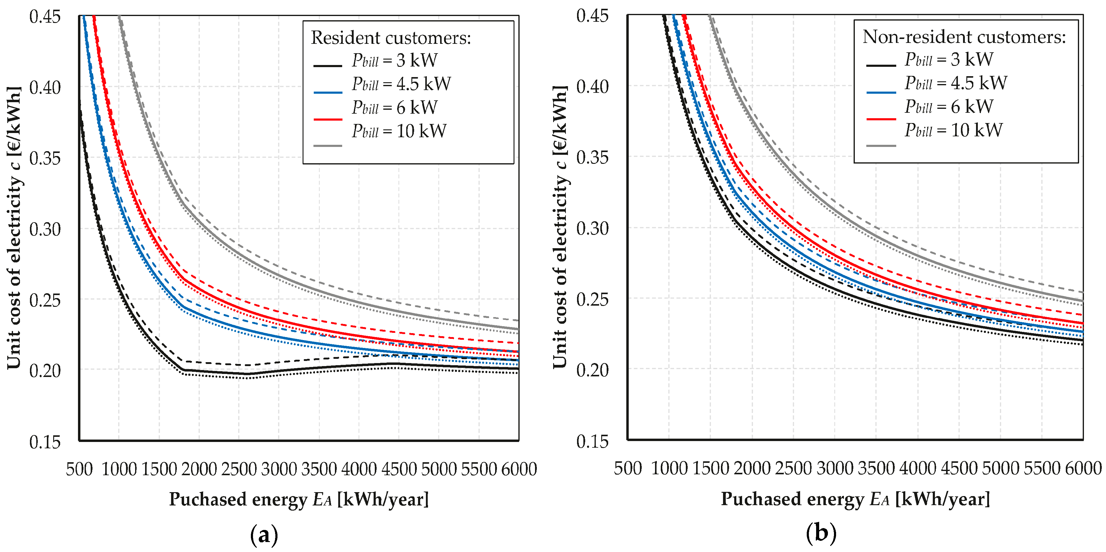
Maximum power absorption
PA,max, defined through Equation (25) and impacting the contractual power of the end-user supply
Pbill (kW) as in Equation (26), and maximum power injection
PI,max according to Equation (27). In the Italian context,
Pbill can assume the values 3, 4.5, 6, or 10 kW. It should be noted that introducing a BESS could be a way to reduce the end-user’s contractual power
Pbill, thus reducing some of the components of the electricity bill.
Energy absorption
EA (kWh), evaluated in a long-term time period
T (e.g., one year). The reduction of the purchased energy is one of the BESS economic benefits. For the bill computation, the overall consumption
EA is divided considering peak hours (
EA1 (kWh), from Monday to Friday, from 8 a.m. to 7 p.m. [
8]) and other time periods, such as nighttime, weekends, and holidays (
EA2 (kWh)).
Energy sold to the public network EI (kWh), i.e., one of the investment revenues according to the considered selling pricing mechanism, evaluated in a long-term time period T. Parameters Pbill, EA, and EI, computed in different scenarios (passive end-user, active end-user with the sole PV unit, and smart end-user integrating the BESS), will be used to evaluate the BESS economic advantages according to the presently-adopted schemes for pricing purchased and sold energies.
According to Reference [
48], the self-sufficiency ratio
SSR and the self-consumption ratio
SCR, evaluated by Equations (28) and (29), respectively:
The battery energy consumption
EH (kWh) for maintaining the internal temperature higher than the minimum threshold
Tm. In the observation period
T,
EH is the sum of the heater consumption
PH(
t) multiplied by the elementary time interval ∆
t, as described in Equation (30):
The battery aging
A (cycles) consequent to its operation in the time period
T. An advanced battery lifetime prediction model is introduced in Reference [
53], in which a lead-acid battery pack supplies frequent partial charging/discharging cycles. In this paper, for the purpose of simplicity and considering that the BESS operation respects all the battery constrains (e.g., admitted charging/discharging power, So C range, etc.), the effective cycle counting method is used as lifetime model [
54]. Thus, the parameter
A is obtained through Equation (31), by considering the sole discharging phases (when
PB(
t) > 0). However, it is important to note that partial discharges of the storage system have a very weak effect in terms of battery aging in comparison with deep discharges. Therefore, the way parameter
A is obtained involves a precautionary over-estimation of the battery aging, since the effective lifetime could be longer, having positive impacts on the business plan of the BESS investment.
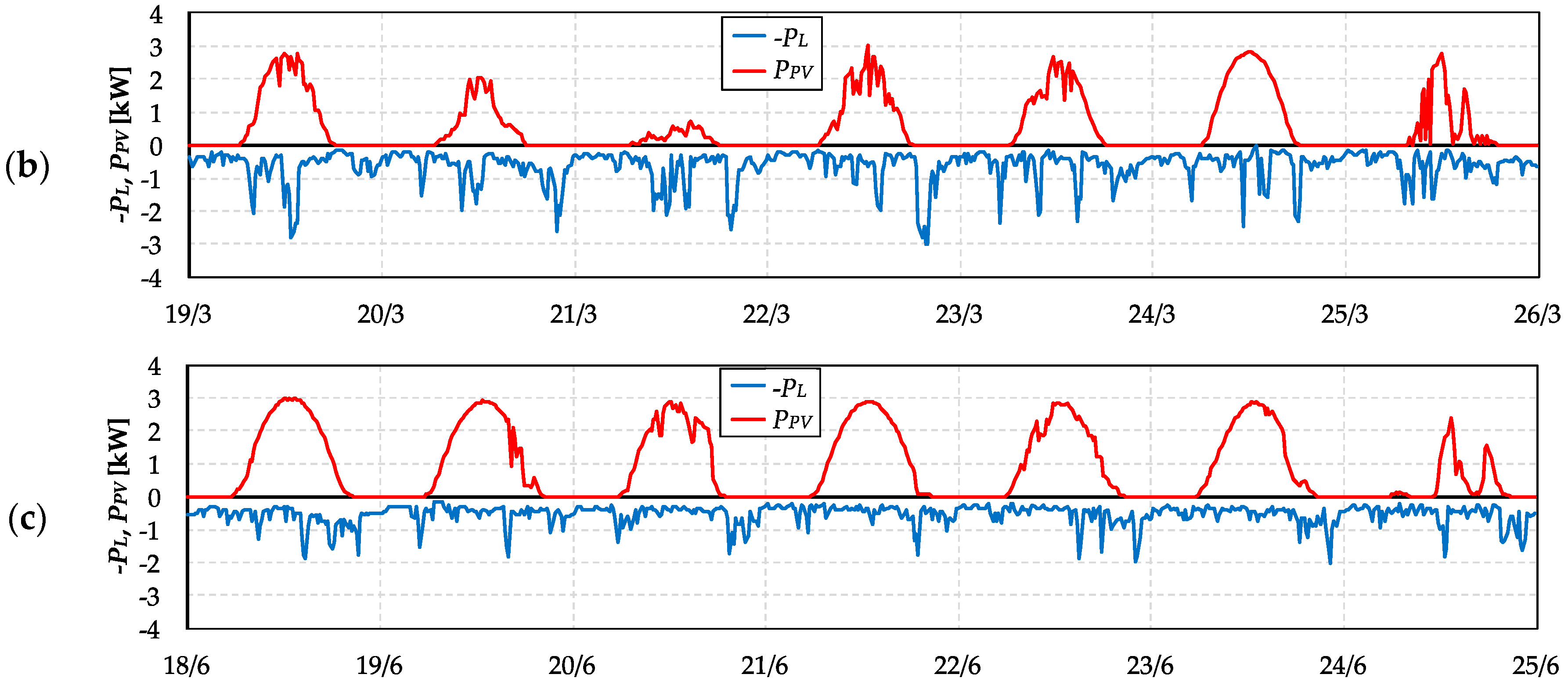
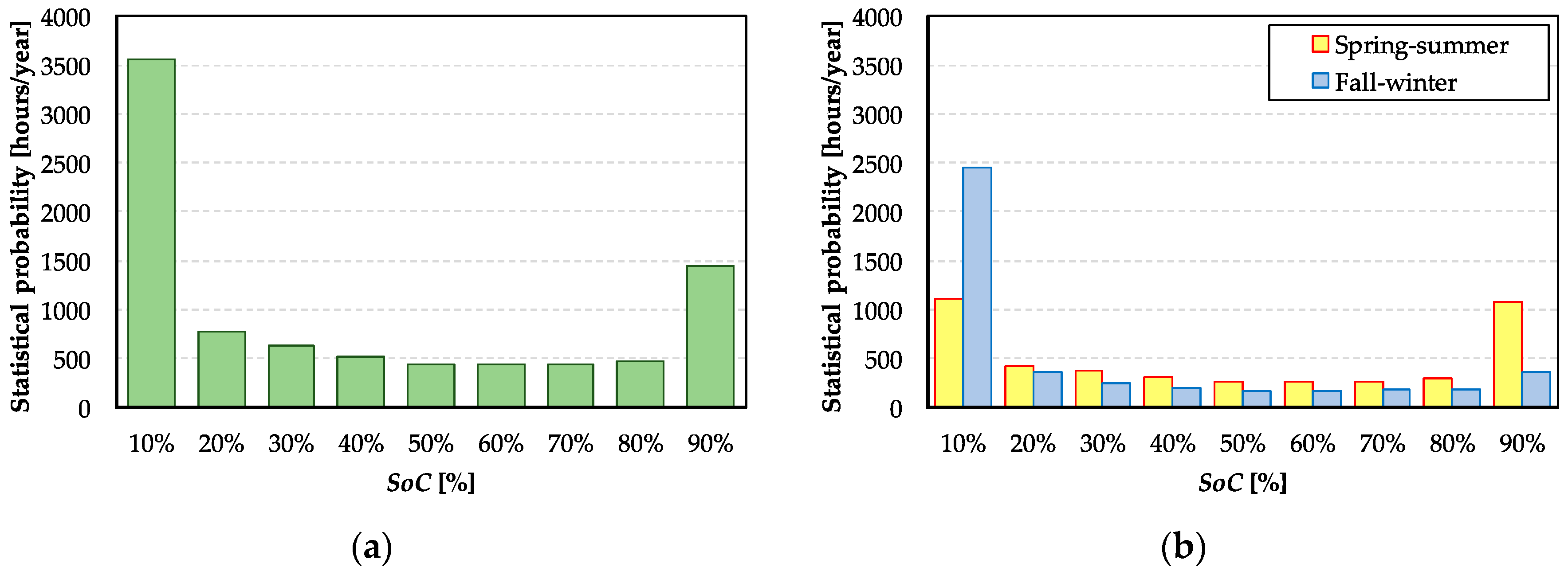
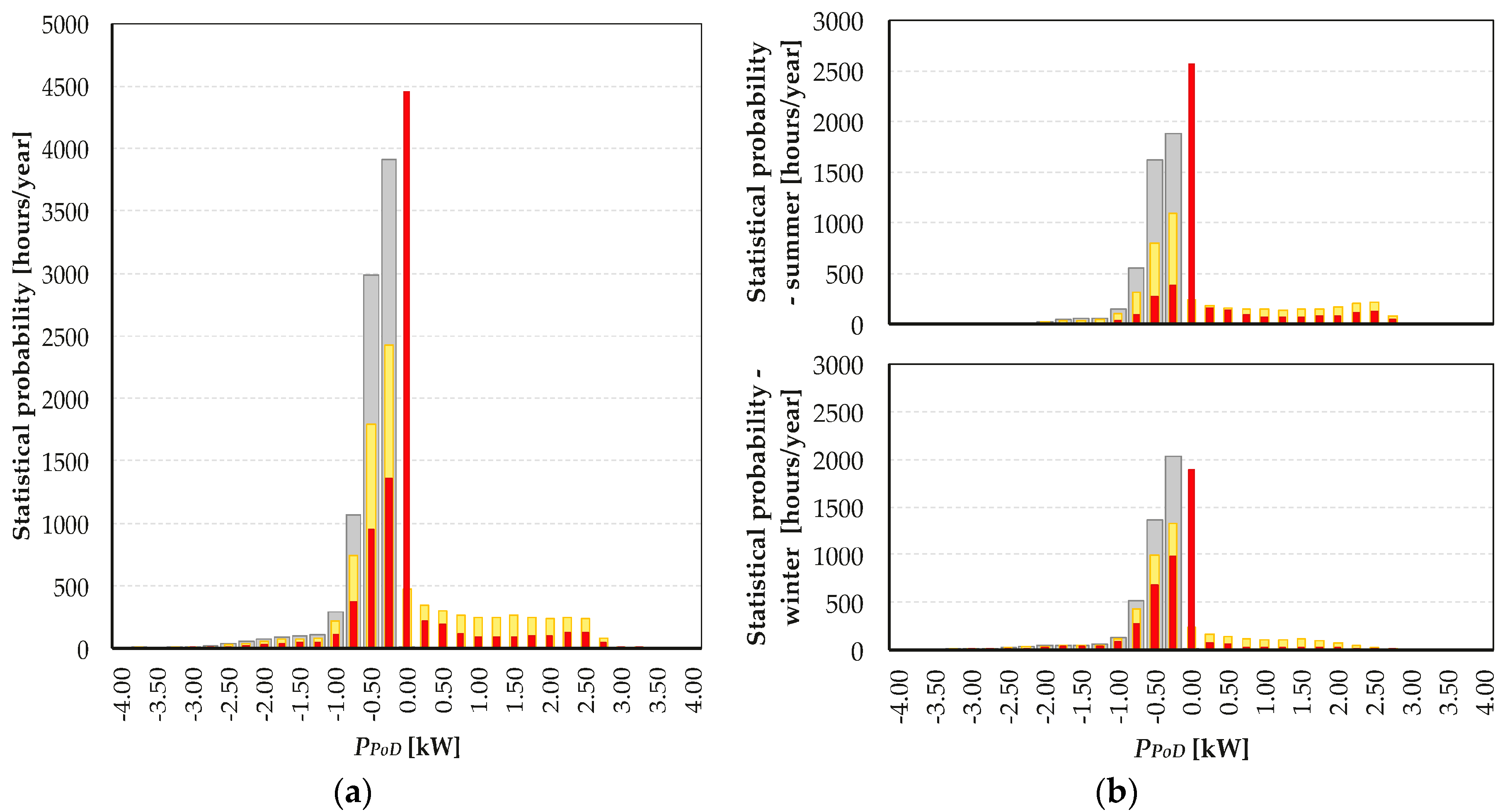
Statistical distribution of the most representative parameters, such as the power exchange
PPoD between the end-user and the public network, the battery power contribution
PB, and the BESS SoC, are obtained. The minimal SoC frequency
MSF, i.e., the relative time in which the BESS SoC is close to
SoCm, is computed as suggested in Reference [
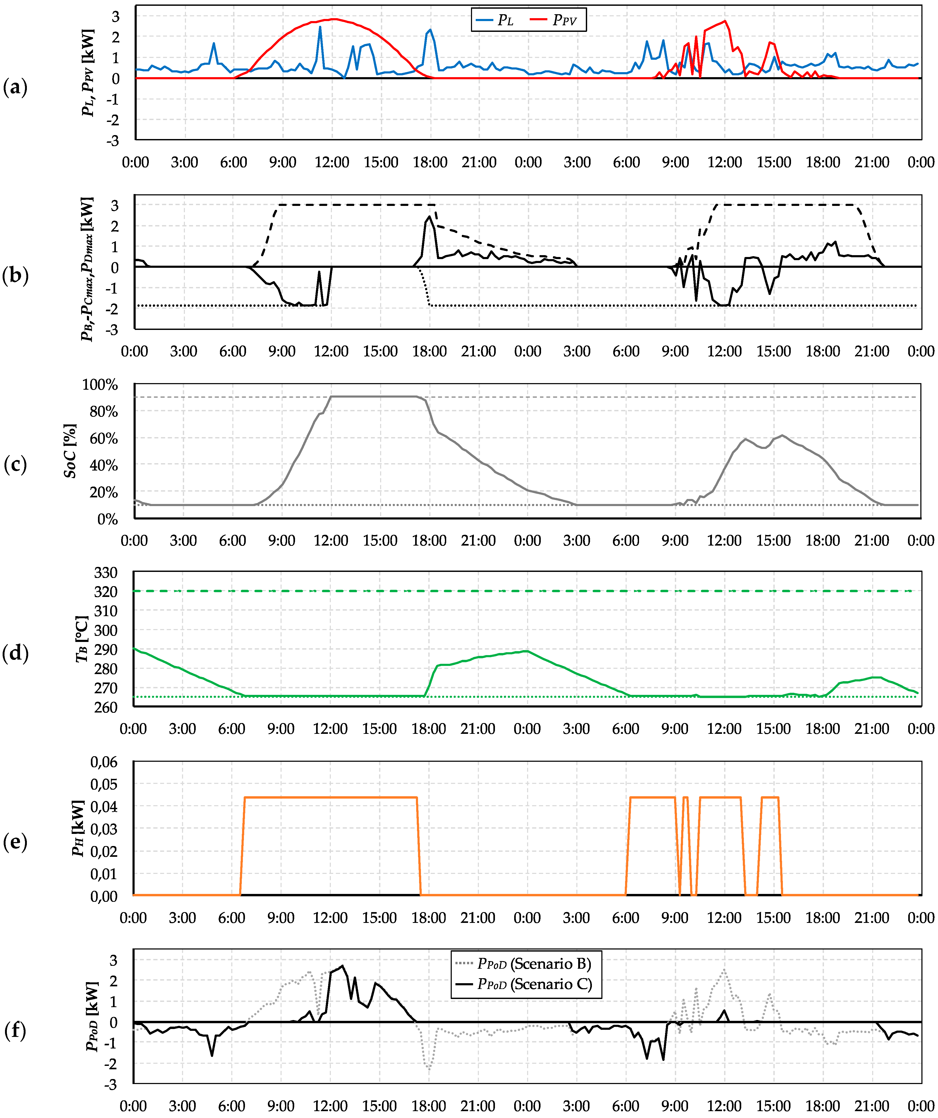
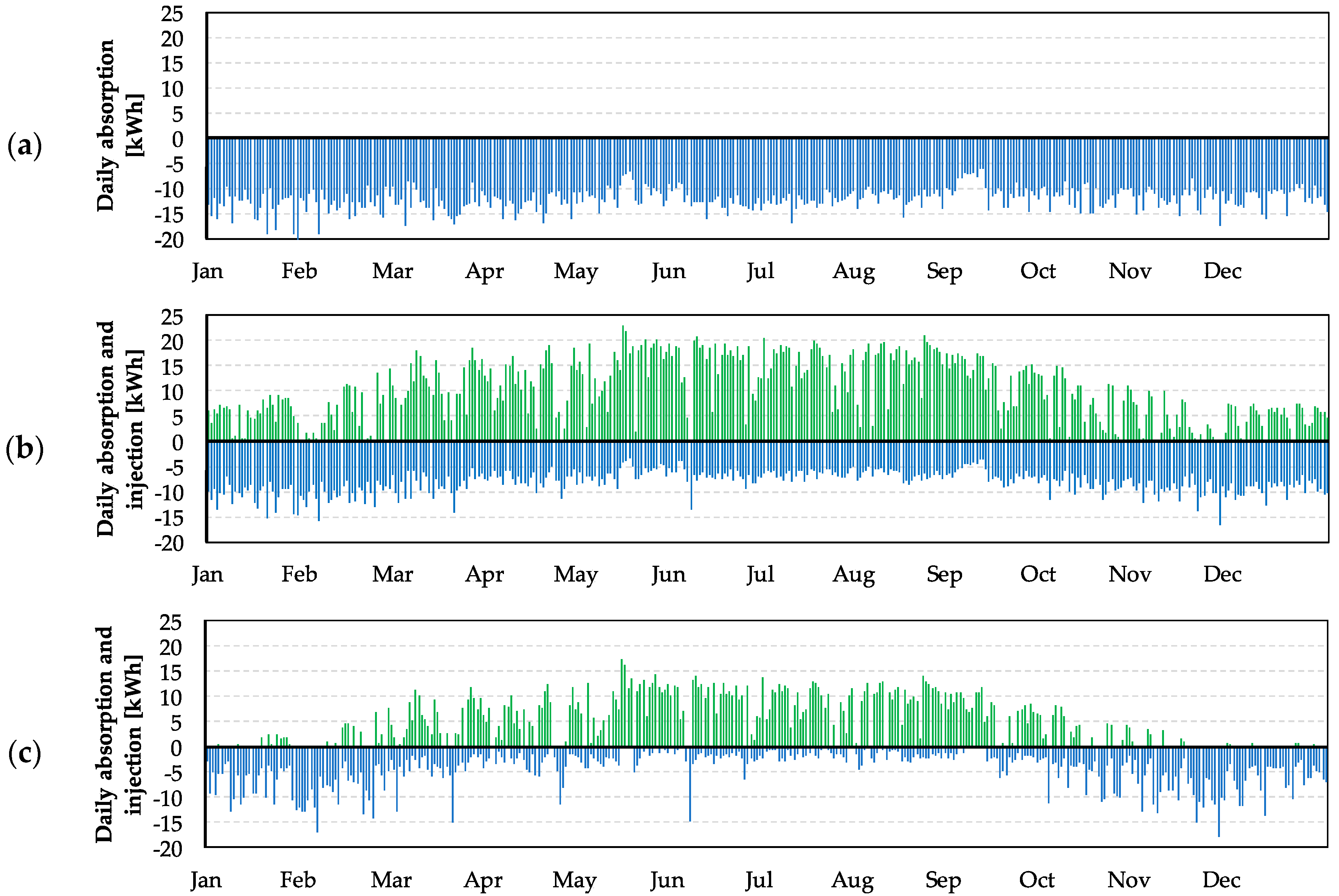
48]. In addition, for a deeper comprehension of the model considering the seasonal variations of both the load consumption and the PV generation, the main outputs are displayed separately for the spring-summer period (from 21 March to 21 September) and for the fall-winter phase. This analysis allows for the identification of the parameters that have the greatest influence on the overall economic interest in the BESS installation, e.g., the thermal consumption for preserving the battery internal temperature.
Finally, the average variation of the power exchange
PPoD, named as ∆
PPoD (kW), is evaluated for all the analyzed configurations through Equation (32) to give an immediate representation of how much the power profile is variable depending on the load behavior, combined with the solar availability and the BESS management strategy. This parameter is very interesting from the DSO’s point of view, since very quick actions to regulate the network operating conditions are required in the case of a high value of ∆
PPoD.


