Article

A Feedback Passivation Design for DC Microgrid and Its DC/DC Converters

1
College of Electrical Engineering, Zhejiang University, Hangzhou 310027, China
2
State Grid Zhejiang Electric Power Company, Hangzhou 310007, China
*
Author to whom correspondence should be addressed.
Energies 2017, 10(1), 14; https://doi.org/10.3390/en10010014
Submission received: 22 October 2016 / Revised: 27 November 2016 / Accepted: 13 December 2016 / Published: 23 December 2016
(This article belongs to the Collection Smart Grid)

Abstract

:
There are difficulties in analyzing the stability of microgrids since they are located on various network structures. However, considering that the network often consists of passive elements, the passivity theory is applied in this paper to solve the above-mentioned problem. It has been formerly shown that when the network is weakly strictly positive real (WSPR), the DC microgrid is stable if all interfaces between the microgrid and converters are made to be passive, which is called interface passivity. Then, the feedback passivation method is proposed for the controller design of various DC–DC converters to achieve the interface passivity. The interface passivity is different from the passivity of closed-loop systems on which the passivity based control (PBC) concentrates. The feedback passivation design is detailed for typical buck converters and boost converters in terms of conditions that the controller parameters should satisfy. The theoretical results are verified by a hardware-in-loop real-time labotray (RTLab) simulation of a DC microgrid with four generators.

1. Introduction

With the deterioration of the environment and the reduction of fossil reserves, applications of renewable energy and energy storage systems (ESSs) are rapidly increasing.Most of these new components have a DC feature in essence, which may pose technical and operational challenges for the integration into the existing AC systems. Meanwhile, significant advances in power electronics technology have produced a number of power converters for DC voltage transformation into various levels for different applications. In this context, DC microgrids are emerging as an attractive solution for the integration of renewable-based distributed generators (DGs) and ESSs [1].
The stability of DC microgrids is a critical problem. Its studies have been performed by small or large signal analysis [1,2,3,4,5,6,7,8,9], in which the DC microgrid is analyzed collectively, based on a comprehensive model of the whole microgrid. The comprehensive model is sensitive to the change of every unit, particularly to the fluctuation of the microgrids’ network. The results based on such a high entropy model may have limited effectiveness in providing valuable information for stable design [10]. This paper follows a decomposition approach in which the DC microgrid is analyzed as a network with two parts: a node system consisting of converters and a dynamical edge system consisting of loads and transmission lines to connect the converters and loads. The nodes and edges division is compared to results of a work on a multi-agent systems [11]. According to [11], the outputs of the edge dynamic systems form the external inputs of the node dynamic systems, which are termed “neighboring inputs” representing the coupling actions between nodes. The outputs of the node dynamic systems are the inputs of the edge dynamic systems. As explored in [12], an edge system consisting of resistor-lnductor-capacitor (RLC) components is positive real (PR), or weakly strictly positive real (WSPR) if there exists at least one resistance inside. As it is well-known that the passivity is preserved when two passivity systems are connected properly, this paper makes a passivity design for the converters in a DC microgrid. When each converter has a passive interface, then the DC microgrid with a WSPR (weakly strictly positive real) edge system is guaranteed to be stable.
The passivity-based control (PBC), as a kind of passivation design, has been extensively utilized on the control of converters. In [13], passivity-based feedback controllers are derived for the indirect stabilization of the average output voltage in pulse-width-modulation (PWM) controlled DC–DC power converters of the ”boost“, “buck-boost“, and “buck“ types. In [14], the authors present an overview of passivity-based stability assessment, including techniques for space-vector modeling of VSCs (voltage source converters) whereby expressions for the input admittance can be derived. In [15], the author investigate the DC-bus voltage regulation problem for a three-phase boost type PWM AC–DC converter using PBC theory. The models are shown to be Euler–Lagrange (EL) systems corresponding to a suitable set of average EL parameters.The PBC aims to make the controllers themselves be passive, which together with a passive plant stabilizes the closed-loop system. In contrast, the passivity design made by this paper focuses on the interface passivity instead of the passivity of controllers. The interface passivity is a kind of passivity equivalent to the PRness of transfer functions from injecting currents of microgrid i T to output voltages of converters u c . i T and u c are the output and the input of edge systems, respectively.
In passivity theory, the Kalman–Yakubovich–Popov (KYP) Lemma establishes an equivalence between the conditions in the frequency domain for a system to be positive real, an input–output relationship of the system in the time domain, and conditions on the matrices describing the state-space representation of the system. With the KYP Lemma, many significant results in the control field have been presented for the direct passivation regulating the input–output relationship [16,17], while a few results exist for the indirect passivation regulating the relationship between external input and output [18,19]. The interface passivity addressed in this paper is a kind of indirect passivation that is more difficult than direct passivation since external input can not be controlled. On the contrary, the PBC control is a kind of direct passivation. In [19], necessary and sufficient conditions for the feasibility of indirect passivation of strictly positive real (SPR) was presented for a class of single-input and single-output systems. It should be pointed out that typical DC–DC converters, including “buck” and “boost”, do not satisfy the necessary and sufficient condition. This paper proposes a feedback passivation design for DC–DC converters to make them have interface passivity. The resulted transfer functions are PR rather than SPR in the penalty of requiring edge systems to be WSPR rather than PR.
Making a converter’s interface be passive is not new. Gu et al. [18] have addressed this subject recently by using a feedforward control method of SISO (single input single output) systems in the frequency domain. In this paper, the interface passivity is discussed in the time domain.In contrast to the frequency domain analysis, the time domain analysis utilizing state-space representation is possible to confirm the state of the system parameters and not merely input–output relations. Moreover, it fits with in the multiple-input and multiple-output essence of two parts of DC microgrids, while the SISO method of frequency domain omitting the off-diagonal coupling term is not rigorous for microgrids. The main contributions of this paper are: (1) a decoupling viewpoint of DC microgrids by which the stability is guaranteed by the interface passivity of node system and the WSPR of the edge system, independent of the network structure; and (2) a feedback passivation method is proposed for controlling typical converters to be of the interface passivity.
The remainder of this manuscript is organized as follows. Section 2 relates the stability of the DC microgrid to the interface passivity. 
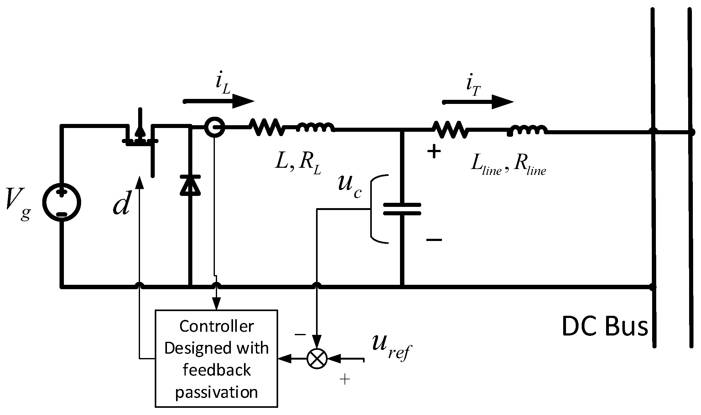
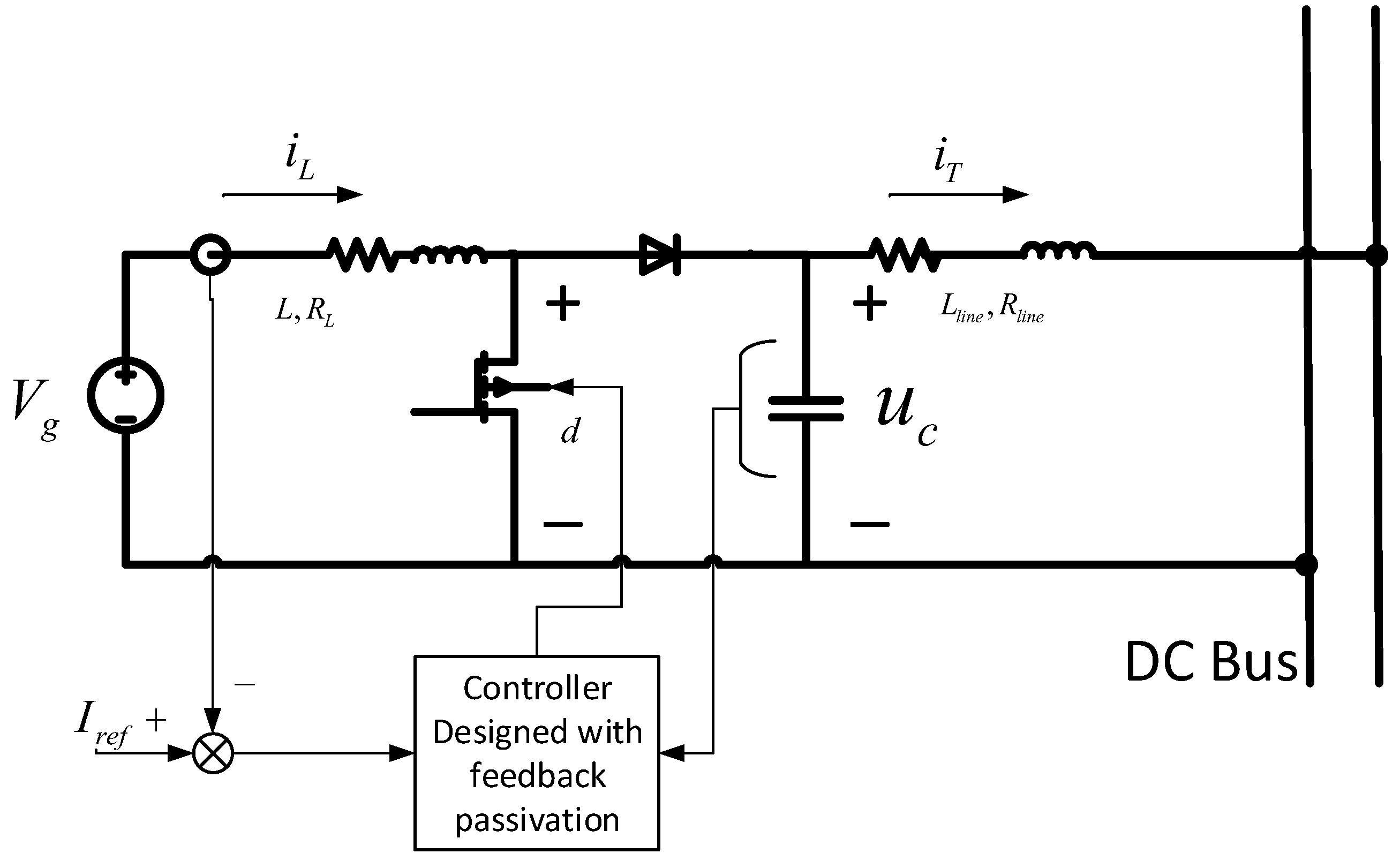
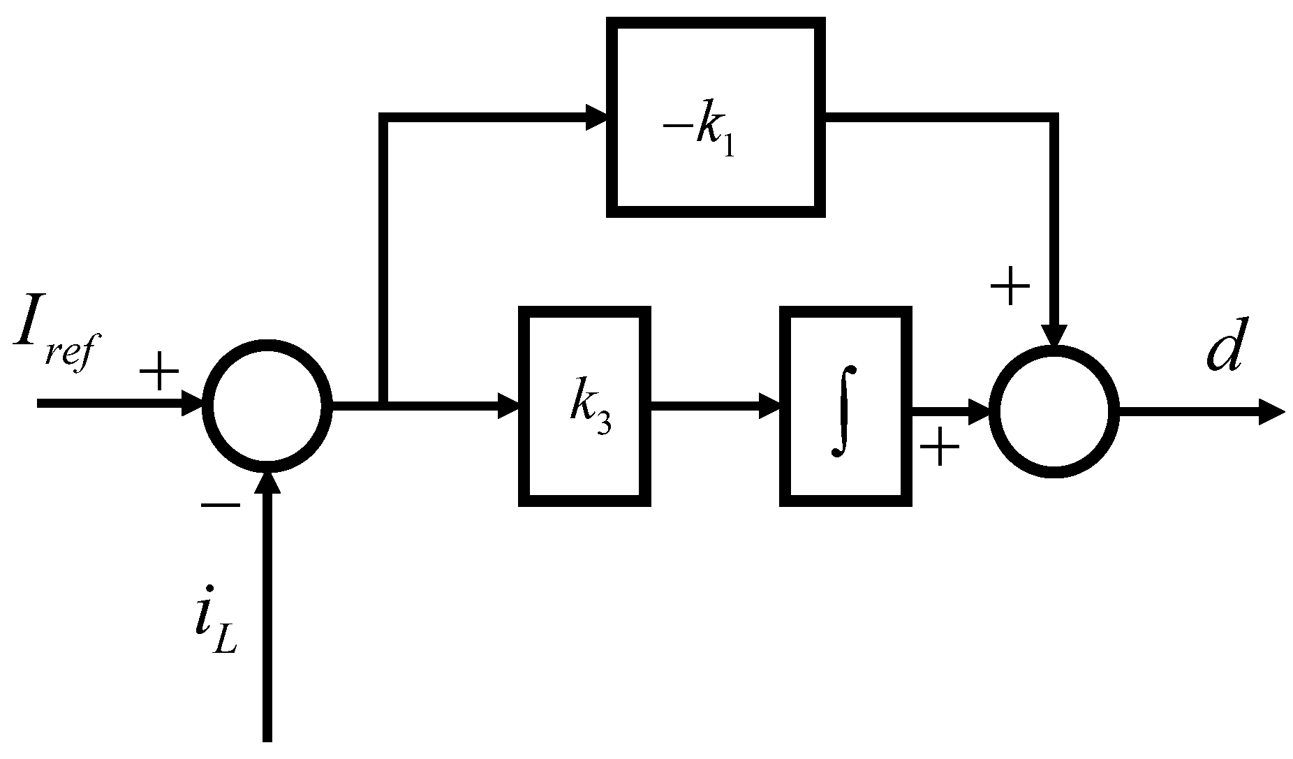
Section 3 details the feedback passivation design of typical DC converters. Section 4 makes a hardware-in-loop real-time laboratory (RTLab) (version 10.7, OPAL-RT Technologies Inc., Montréal, QC, Canada) simulation to verify the analytic results, followed by conclusions in Section 5.

2. Passivity Criterion of Converters in DC Microgrids

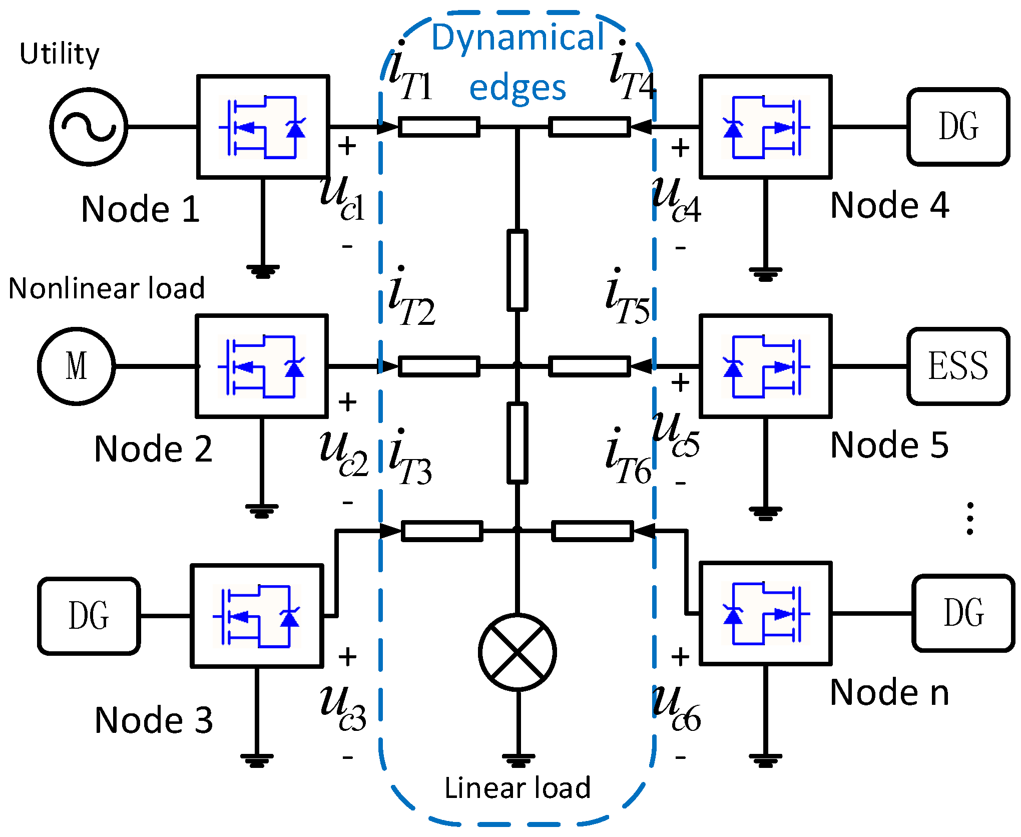
In this section, the DC microgrid is analyzed as a network with two parts: dynamical edges and nodes. The structure is shown in Figure 1. The first part is composed of transmission lines and loads, and another part is composed of converters. According to [11], a multi-agent system is often described by a graph, where nodes represent the dynamic subsystems and edges the interactions between these subsystems. One benefit of the division is that we can take advantage of the the passivity of transmission lines more intuitively. That is, the feedback interconnected system of two passive subsystems is passive then stable. From the viewpoint of power electronics, the division of the nodes and dynamical edges makes it easy to depict the requirement of the interfaces, due to the fact that, in a microgrid system, the nodes (converters) under control are connected via dynamical edges (transmission lines and loads). For a certain structure of the dynamical edges, a common requirement can be put forward to every interface. As a result, it is convenient for applying distributed control law for the nodes.
Denote the vectors that collect the current injections and output voltages of converters and loads by i T and u c , respectively. We then have:
u c = Z N i T
where Z N is a diagonal transfer function matrix between i T and u c , in which the controller going to be designed is included.
Meanwhile, denote Y as the admittance transfer function matrix between the output voltage u c and the injecting current i T of the network composed by transmission lines, that is:
i T = Y u c
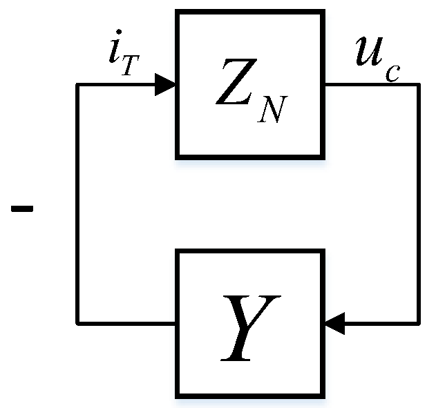
The system composed of Equation (1) and Equation (2) admits the compact block-diagram representation in Figure 2. The converters, loads and the transmission lines are connected via a feedback interconnection. Stable conditions are given based on the feedback interconnection.
Theorem 1.
If all elements in Z N are PR, when Y is weakly SPR, the microgrid is asymptotically stable.
Proof. 
When Z N and Y are PR and weakly SPR, respectively, from [20] (Lemma 3.37), the feedback interconnection in Figure 2 is asymptotically stable.  ☐
Remark 1.
The theorem that a system composed of two PR subsystems via feedback interconnection is PR is well-known in passsivity theory. However, it should be mentioned here that passivity yields Lyapunov stability but not asymptotical stability. For instance, 1 s is passive but not stable. In [18,21,22], etc., the authors assert the stability only based on the interconnection of PR systems. Even though similar assertions are always true in circuits’ analysis, it is essential to explain the fact theoretically. From Definition 2.53 of [20], a PR system is weakly SPR when it is Hurwitz. The assumption of Y is reasonable for when the transmission lines contain resistive elements. Then, Y is Hurwitz, while the edge system consisting of RLC components is passive itself according to [12].
In fact, Z N acts like an “interface impedance” of the nodes in a sense. The nodes can also be expressed in an “admittance” form, that is, a transfer function matrix (denote as Y N ) with the input u c and the output i T . Similarly, the dynamical edges also have the form of an impedance matrix (denoted as Z). To construct the interconnection feedback structure according to the passivity theory, we have two ways to describe the whole system, using ( Z N , Y ) shown in Figure 2 or ( Y N , Z ) shown in Figure 3. ( Z N , Z ) and ( Y N , Y ) are not proposed for the reason that, in these cases, we may encounter the problem as follows: firstly, Z 1 or Y 1 may not exist. Secondly, when Z or Y is WSPR, the inverse of them may not be WSPR. For example, s s + 1 is WSPR while s + 1 s is not. In several past works, the analysis are based on admittances or impedances only, and risks will be taken.
Without loss of generality, the following analysis is based on the structure shown in Figure 2. As Figure 2 shows, in fact, Z N and Y represent the influence on the stability from converters, loads and electrical network, respectively. Due to the feedback interconnection and the weak SPRness of Y, making every transfer function in Z N be PR is a convenient way to stabilize the closed loop. It should be mentioned that the loads are passive according to Definition 2.1 in [20]. Ths is to make the grid-connected interfaces of converters be passive and then Z N is passive.
By the way, the result in Theorem 1 is always true, regardless of the structure changing—for example, the plug and play of distributed generators (DGs) or ESSs and the fluctuations of loads and transmission lines. The remainder of the paper is focused on the interfaces’ passivation problem for converters.

3. Feedback Passivation

This section focuses on designing a controller to comply with the interface passive criteria described above.

3.1. Preliminary

The PBC theory offers a systematical method for system passivation, which is successfully applied to controlling many kinds of converters, including buck, boost, buck-boost and three-phase DC–AC VSCs [13,15,21,22,23]. However, these approaches concentrate on the passivity seeking between the control input and output but not the one with respect to external input and output, required by the interface passivity.
In [19], the authors derive necessary and sufficient conditions for the existence of a control law that renders the closed-loop system SPR with respect to an external input. However, most DC–DC converters, including those considered in this paper, do not satisfy the conditions. Considering that the edge system is WSPR, the goal of feedback passivation on DC–DC converters is relaxed to seek the PR, weaker than the SPR. The necessary and sufficient conditions for the feasibility of rending a system PR with respect to an external input is still an open problem. This section does not challenge it but presents sufficient designs to realize it for some typical DC–DC converters, which is still challenging and new.
Another difficulty arises from the requirement of unbiased tracking, which is often realized by a proportion integration (PI) controller. In contrast to the static feedback control, PI control is a dynamic control introducing extra state variables. This poses some structure limitations on the feedback passivation design.
The state-space equation of a converter with dynamic controller can be written as:
x ˙ = A x + B u + G ω z = H x
where x represents the state variables from the converters and the associated dynamic controller, u, is the control input, with z the output and ω the external inputs. The goal of feedback passivation now is to find a control law:
u = K x
to make the transfer function from ω to z be PR, i.e., interface passivity.
For the convenience of the analysis below, review the following lemma firstly, derived from the KYP lemma.
Lemma 1.
Consider the closed system composed by system Equation (3) and the control law Equation (4), and denote A c = A + B K . The interface, i.e., transfer function from ω to z is passive if there exists a P that satisfies:
P = P T P > 0 P G = H T
This makes:
P A c + A c T P 0

3.2. Feedback Passivation for Buck Converters

The buck converter operating in the voltage source mode is shown in Figure 4. With a classical averaging method, the state-space model is given by:
L i ˙ L = d V g i L R L u c + d i L R L u c = R L i L u c + V g d C u ˙ c = i L + i T
When the converter operates in the voltage source mode, the compensator containing an integrator is:
ξ ˙ = u r e f u c d = u = k u u c + k i ξ + k L i L k u u r e f
In the analysis below, u r e f will be ignored, due to the fact that, according to the internal model principle in output regulation theory. When the closed loop system is stable, the asymptotically tracking of u r e f is naturally realized. Write Equation (7) and Equation (8) together, and the state- space equation of the open-loop system is given in the form of Equation (3), where:
x = i L u c ξ u = d ω = i T z = u c A = R L L 1 L 0 1 C 0 0 0 1 0 B = V g L 0 0 G = 0 1 C 0 H = 0 1 0
and the state feedback is:
u = K x
Theorem 2.
For the buck circuit shown in Figure 4, when:
K = [ k 1 , k 2 , k 3 ]
satisfies:
k 1 < 0 k 2 < 0 0 < k 3 < R L L V g
the interface, i.e., the transfer function from i T to u c , is passive.
Proof. 
Under the control law Equation (11), the closed loop A + B K can be denoted as:
A c = R L k 1 V g L 1 k 2 V g L k 3 V g 1 C 0 0 0 1 0
When P 1 is selected as:
P 1 = ( k 2 1 V g ) V g L 0 1 0 1 C 0 1 0 V g k 1 R L k 3 V g
as a result:
A c P 1 + P 1 A c T = k 3 V g L k 2 1 V g k 1 R L V g 0 0 0 0 0 0 0 0 0
Considering Lemma 1, Equation (6) is equivalent to Equation (15); thus, interface passivity is achieved.   ☐
Remark 2.
In Theorem 2, an intuitive design method is given, and it is easy to use for engineering practice. Because the proposed method can be treated as a classical dual-loop control law with an inner current loop and an outer voltage loop, the gain of the inner loop is k 1 and the P I parameters of the outer loop are k 2 k 1 and k 3 k 1 . From the design point of view, we just need to consider Equation (12) as an additional requirement of the dual-loop design method as Figure 5 shows, which can be applied intuitively for engineering practice. From the physical sense, k 1 and k 2 reflect the damping of the inner loop and the outer loop respectively. From Equation (15), it is found that k 3 can not be too large to keep the semi-negativeness of A c P 1 + P 1 A c T . Meanwhile, k 3 should be positive to keep A c = k 3 V g C < 0 , which represents the product of three eigenvalues.

3.3. Feedback Passivation for Boost Converters

For boost converters shown in Figure 6, the large-signal model can be obtained, through a classical modeling method of averaging, that:
L i ˙ L = d V g i L R L + d V g i L R L u c = R L i L d u c + V g C u ˙ c = d i T + d i L + i T = d i L + i T
and the compensator here is:
ξ ˙ = I r e f i L , d = u = k u u c + k i ξ + k L i L
In this case, the converter operates as a current source. The small-signal model of the open loop system can be obtained by linearization in the form of Equation (3), where:
x = i ^ L u ^ c ξ ^ u = u ^ ω = i ^ T z = u ^ c A = R L L D 1 L 0 1 D C 0 0 1 0 0 B = U c L I L C 0 G = 0 1 C 0 H = 0 1 0
and the state feedback is:
u = K x
In Equation (18), D, U c and I L are the parameters of the equilibrium point. Different from the aforementioned buck circuit, whose regulated output is the interface’s output voltage itself, for the boost circuit here, the regulated output is not the interface’s output voltage but the inductor’s current. As a result, another equation representing the regulated output is:
i ^ L = 1 0 0 i ^ L u ^ c ξ ^
Familiar with the analysis of the buck converter, when the stability is achieved, the asymptotically tracking of I ^ r e f is realized, so I ^ r e f and the output of Equation (20) is ignored in the following analysis.
Theorem 3.
For the boost circuit shown in Figure 6, when:
K = k 1 0 k 3
where k 1 < 0 , 0 < k 3 U c k 1 R L k 1 I L + D 1 I L L , the interface, i.e., the transfer function between i T and u c , is passive.
Proof. 
With feedback gain K, denote A + B K = A c , where:
A c = U c k 1 R L L D 1 L U c k 3 L 1 D I L k 1 C 0 I L k 3 C 1 0 0
According to Lemma 1, the interface is passive if there exists a P that satisfies Equations (5) and (6). Here, select P as:
P = L a 1 0 L a 2 0 C 0 L a 2 0 a 3 > 0
where:
a 1 = k 1 I L D 1 + 1 R 0 L a 1 a 2 < 0 a 3 = a 1 a 2 R z a 2 R 0
with:
R 0 = R L U c k 1 R z = ( 1 D ) U c I L
As a result:
P A c + A c T P = 2 a 1 R 0 2 L a 2 0 0 0 0 0 0 0 2 a 2 2 R z 0
and the interface passivity is achieved.   ☐
Remark 3.
In Theorem 3, the physical meaning of R 0 and R z is obvious. The former parameter is equivalent to increase the resistance of the inductor, while the later one can be treated as an equivalent load of the circuit. The proposed control law can be understood as a modified single current loop P I controller, with P I parameters k 1 and k 3 , as Figure 7 shows. The control law is also applicable in practice. k 1 < 0 keeps the trace of A c (sum of eigenvalues) negative. k 3 should have an upper bound to keep the semi-negativeness of P A c + A c T P , and k 3 > 0 keeps A c = I L k 3 ( D 1 ) C (product of eigenvalues) negative.
The interface passivity and analysis procedures for buck circuits operating as current sources and boost circuit operating as voltage sources are similar to the two conditions discussed above and not presented here.

4. Real-Time Laboratory Experimental Results

In order to verify the proposed feedback passivation method, a DC microgrid test system is built in the RTLab 10.7. 
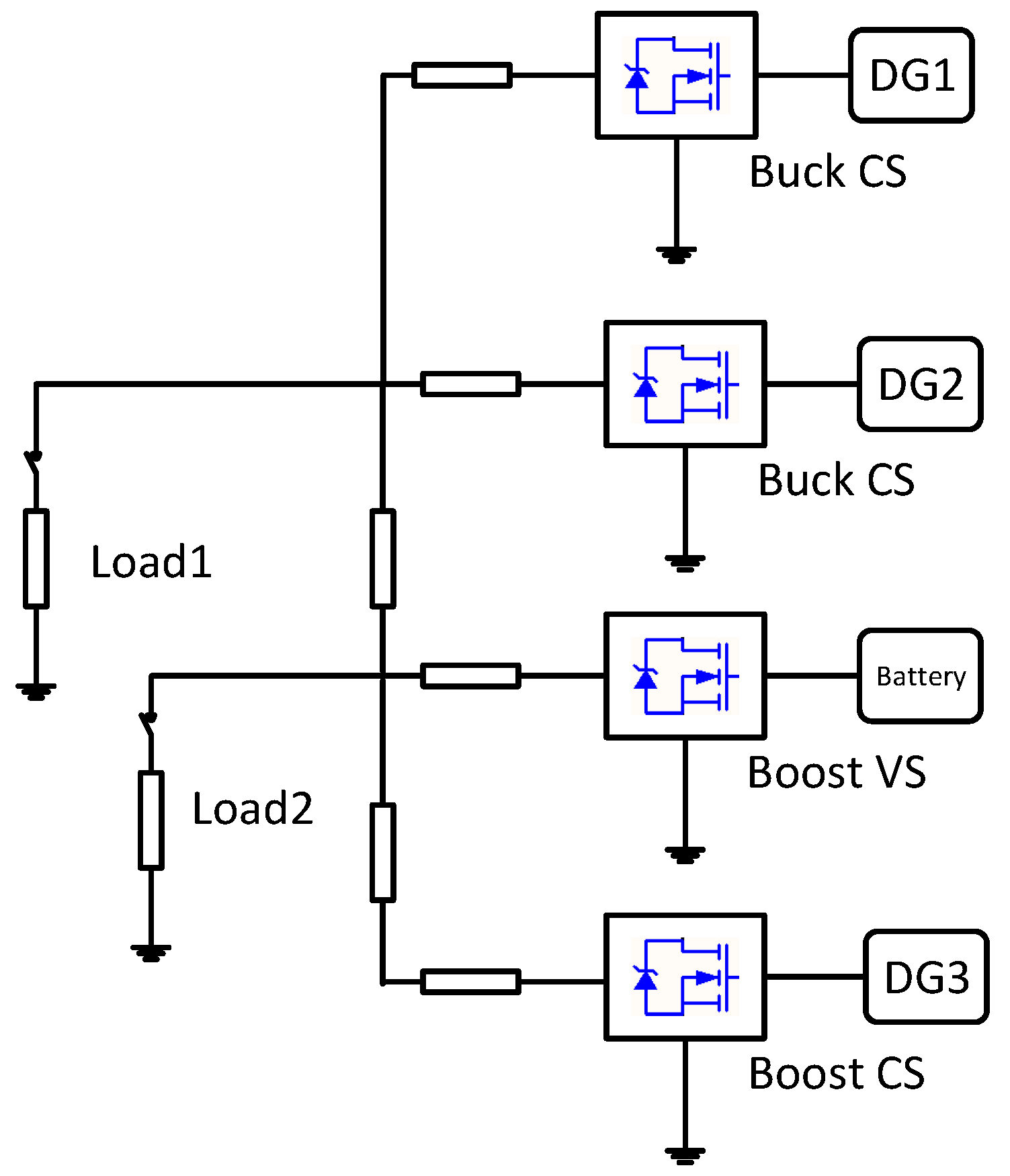
Figure 8 shows the structure of the hardware in loop platform.The system consists of DGs, battery ESSs, local loads and transmission lines.
Three DGs work in current source mode, and the ESS operates in the voltage source mode to maintain the bus voltage at 560 V. Buck and boost circuits are adopted for DC–DC conversion. The detailed converter configurations are listed in Table 1.
In this paper, through the direct code generation method using Matlab (2013b, Mathworks Inc. Natick, MA, USA) and code composer studio (CCS), the proposed passive control algorithm is compiled and downloaded to digital signal processor (DSP) (TMS28335). The control loop in the experiment is realized by external DSP chips, and only the main circuits are simulated in software.

4.1. Test on Feedback Passivation

Firstly, the original passivity criterion is validated. According to the methods proposed in 
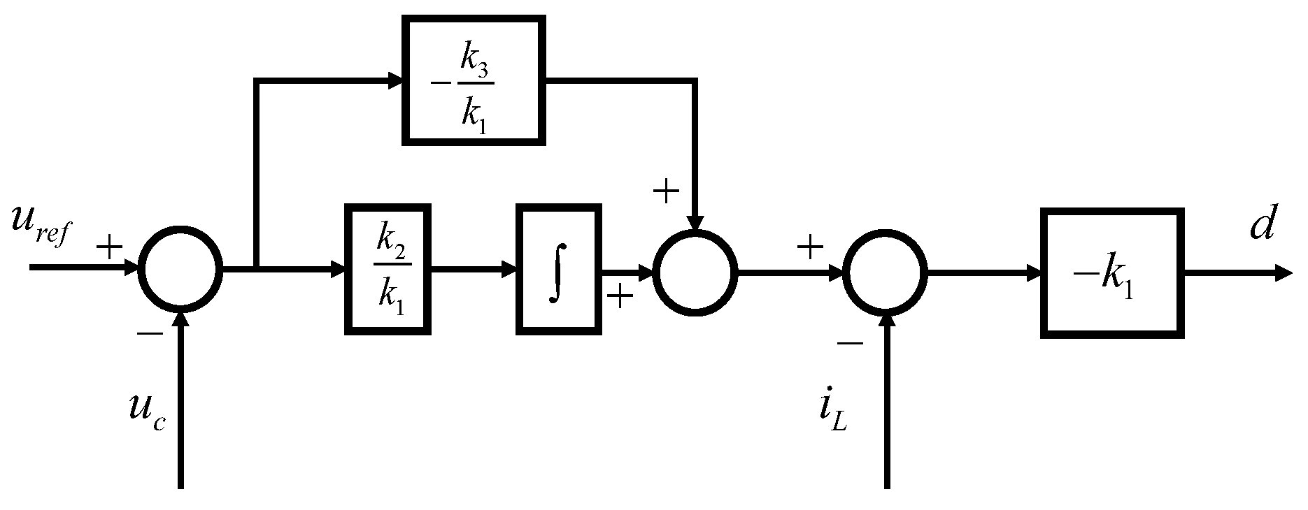
Section 3, based on the control diagrams in Figure 5 and 
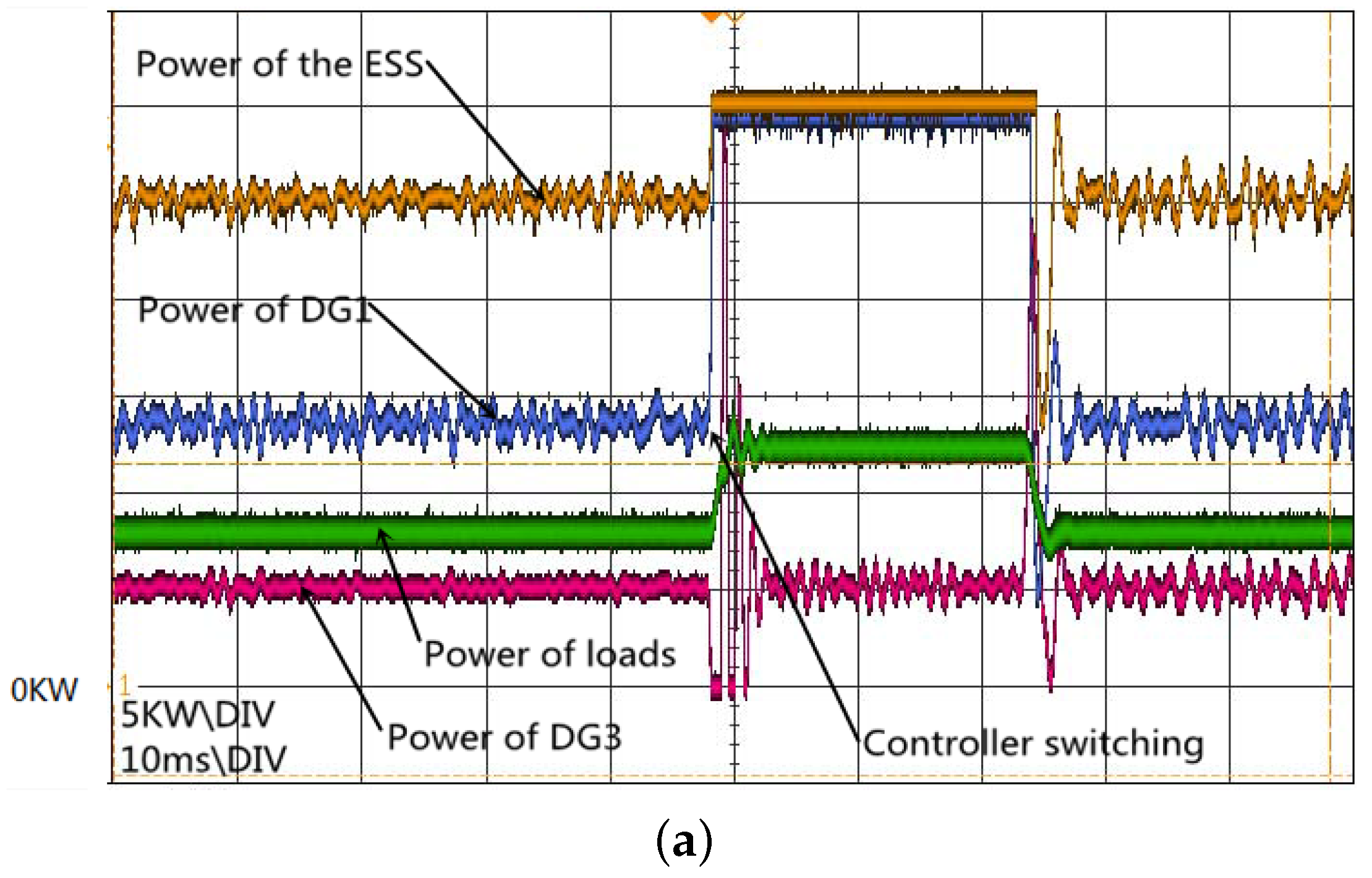
Figure 7, if all converters are controlled under the feedback passivation method to achieve passivity, then the system is stable. As Figure 9a shows, when DG1 and DG2 converters are switched to the conventional dual-loop control to become non-passive, the system experiences a transition first, and then becomes stable with more seriously fluctuating waveforms. In Figure 9b, the two converters are switched back to controllers with feedback passivation and the waveforms restored to be smooth. When three DG converters are controlled to be non-passive, then the system is unstable, as Figure 9c shows. The results above prove the effectiveness of the feedback passivation.

4.2. Test on Stability in Varying Microgrid Structures

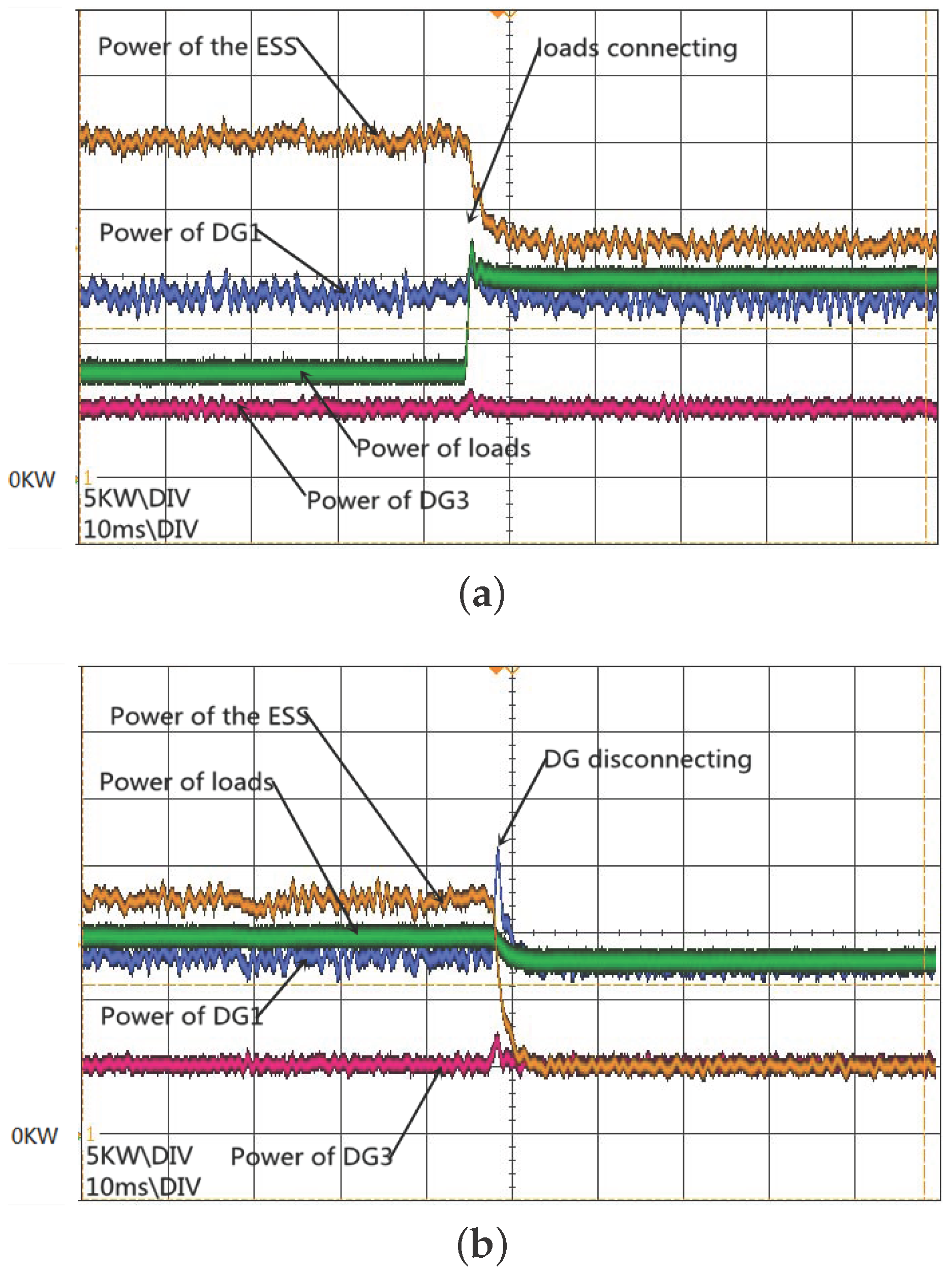
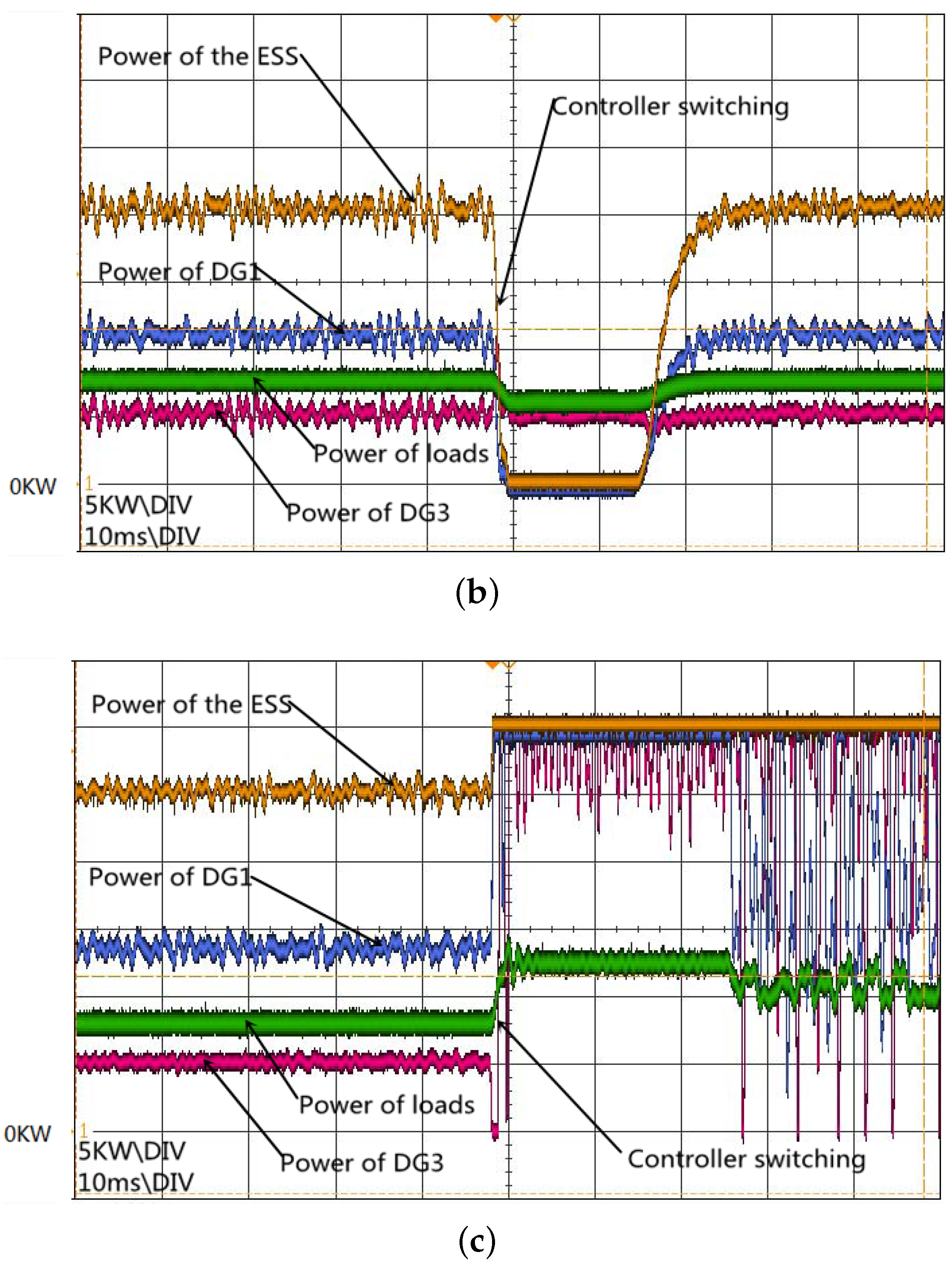
The most obvious advantage of the feedback passivation method is that the stability is always guaranteed no matter to what structure the microgrid changes—for instance, the plug-and-play issue of distributed resources.
To verify this benefit, DGs and loads are switching in this experiment. Three DGs, ESSs and one load (50 Ω, 0.1 mH) are connected to the microgrid initially. Figure 10a shows the transition of the connecting of another load (50 Ω, 0.1 mH). Then, as Figure 10b shows, DG2s are disconnected from the system.
As a comparison, the same procedure is implemented in the scenario while converters of DG1 and DG2 are controlled to be non-passive by the conventional dual-loop controllers and the system is stable. Figure 11a,b show the load connection and DG2 disconnection, respectively.
From the figures above, one can find that the overshoot of the control group is obviously more serious than the group with feedback passivation. For instance, in Figure 10a, no overshoot exists in the power waveform of the ESS, while for the control group, the overshoot is about 2 KW, as Figure 11a shows. The comparison of Figure 10b and Figure 11b confirms the same phenomenon. It should be mentioned that, in Figure 11b, the waveforms’ fluctuation becomes smoother after DG2 disconnection. It is reasonable that the removal of a non-passive part from the system is benefit to stability.

5. Conclusions

Due to the various network structures of DC microgrids, the conventional methods for the stability analysis, by which the microgrids are treated as a whole system, do not seem suitable enough. Because the electrical network often consists of passive elements, the passivity theory is applied to the interface passivity in this paper.
A decoupling viewpoint of DC microgrids is proposed in this paper, by which the microgrid is divided into two parts, including a WSPR electrical network called an edge system and a node system consisting of converters under control. The decoupling method brings convenience to stability analysis due to the fact that when every converter’s interface passivity is achieved, the microgrid is stable. In this paper, the feedback passivation method for typical DC–DC converters is proposed in the time domain, and the proposed method is used in practical applications.
The major contributions of this paper are verified through an RTlab experiment, compared with the typical dual-loop control method, which proves the effectiveness, applicability and robustness of the proposed feedback passivation method.

Acknowledgments

This work is supported by grants from the National 863 Program of China (2015AA050104), the National Natural Science Foundation of China (61374174, 61573314), the Research Project of the State Key Laboratory of Industrial Control Technology of Zhejiang University (ICT1606) and the Science and Technology Project of SGCC (SGZJ0000BGJS1600312).

Author Contributions

Feifan Ji and Ji Xiang conceived and designed the experiments; Feifan Ji performed the experiments; Feifan Ji analyzed the data; Quanming Yue provided the experimental environment; Feifan Ji, Ji Xiang and Wuhua Li wrote the paper. All authors have contributed to the editing and proofreading of this paper.

Conflicts of Interest

The authors declare no conflicts of interest.

Abbreviations

ACAlternating current
CCSCode composer studio
DCDirect current
DSPDigital signal processor
DGDistributed generators
ELEuler–Lagrange
ESSEnergy storage systems
KYPKalman–Yakubovich–Popov
PBCPassivity-based control
PIProportion integration
PRPositive real
PWMpulse-width-modulation
RLCresistor-lnductor-capacitor
SISOSingle input single output
SPRStrictly positive real
VSCVoltage source converter
WSPRWeakly strictly positive real

References

  1. Justo, J.; Mwasilu, F.; Lee, J.; Jung, J.W. AC-Microgrids versus DC-microgrids with distributed energy resources: A review. Renew. Sustain. Energy Rev. 2013, 24, 387–405. [Google Scholar] [CrossRef]
  2. Kahrobaeian, A.; Mohamed, Y.R. Analysis and mitigation of low-frequency instabilities in autonomous medium-voltage converter-based microgrids with dynamic loads. IEEE Trans. Ind. Electron. 2014, 61, 1643–1658. [Google Scholar] [CrossRef]
  3. Kundur, P.; Balu, N.J.; Lauby, M.G. Power System Stability and Control (The EPRI Power System Engineering); McGraw-Hill: New York, NY, USA, 1994. [Google Scholar]
  4. Kundur, P.; Lauby, M.G. Analysis of Electric Machinery and Drive Systems; IEEE Press: Piscataway, NJ, USA, 2002. [Google Scholar]
  5. Katiraei, F.; Iravani, M.; Lehn, P. Micro-grid autonomous operation during and subsequent to islanding process. IEEE Trans. Power Deliv. 2005, 20, 248–257. [Google Scholar] [CrossRef]
  6. Kabalan, M.; Singh, P.; Niebur, D. Large signal lyapunov-based stability studies in microgrids: A Review. IEEE Trans. Smart Grid 2016. [Google Scholar] [CrossRef]
  7. Lu, X.; Sun, K.; Guerrero, J.; Vasquez, J.; Huang, L.; Wang, J. Stability enhancement based on virtual impedance for DC microgrids with constant power loads. IEEE Trans. Smart Grid 2015, 6, 2770–2783. [Google Scholar] [CrossRef]
  8. Shamsi, P.; Fahimi, B. Stability assessment of a DC distribution network in a hybrid micro-grid application. IEEE Trans. Smart Grid 2014, 5, 2527–2534. [Google Scholar] [CrossRef]
  9. Lu, X.; Wan, J. Modeling and control of the distributed power converters in a standalone DC microgrid. Energies 2016, 9, 217. [Google Scholar] [CrossRef]
  10. Middlebrook, R.D. The general feedback theorem: A final solution for feedback systems. IEEE Microw. Mag. 2006, 7, 50–63. [Google Scholar] [CrossRef]
  11. Xiang, J.; Li, Y.; Hill, D. Cooperative output regulation of multi-agent systems coupled by dynamic edges. IFAC Proc. Vol. 2014, 19, 1813–1818. [Google Scholar] [CrossRef]
  12. Anderson, B.; Vongpanitlerd, S. Network Analysis and Synthesis: A Modern Systems Theory Approach; Prentice Hall: Upper Saddle River, NJ, USA, 1973. [Google Scholar]
  13. Sira-Ramirez, H.; Perez-Moreno, R.; Ortega, R.; Garcia-Esteban, M. Passivity-based controllers for the stabilization of DC-to-DC power converters. Automatica 1997, 33, 499–513. [Google Scholar] [CrossRef]
  14. Harnefors, L.; Wang, X.; Yepes, A.; Blaabjerg, F. Passivity-based stability assessment of grid-connected VSCs–An overview. IEEE J. Emerg. Sel. Top. Power Electron. 2016, 4, 116–125. [Google Scholar] [CrossRef]
  15. Lee, T.S. Lagrangian modeling and passivity-based control of three-phase AC/DC voltage-source converters. IEEE Trans. Ind. Electron. 2004, 51, 892–902. [Google Scholar] [CrossRef]
  16. Hoang, H.; Tuan, H.; Nguyen, T. Frequency-selective KYP lemma, IIR filter, and filter bank design. IEEE Trans. Signal Process. 2009, 57, 956–965. [Google Scholar] [CrossRef]
  17. Hoang, H.; Tuan, H.; Apkarian, P. A Lyapunov variable-free KYP lemma for SISO continuous systems. IEEE Trans. Autom. Control 2008, 53, 2669–2673. [Google Scholar] [CrossRef]
  18. Gu, Y.; Li, W.; He, X. Passivity-based control of DC microgrid for self-disciplined stabilization. IEEE Trans. Power Syst. 2015, 30, 2623–2632. [Google Scholar] [CrossRef]
  19. Arcak, M.; Kokotovi, P. Feasibility conditions for circle criterion designs. Syst. Control Lett. 2001, 42, 405–412. [Google Scholar] [CrossRef]
  20. Brogliato, B.; Lozano, R.; Maschke, B.; Egeland, O. Dissipative Systems Analysis and Control; Springer: Berlin/Heidelberg, Germany, 2007. [Google Scholar]
  21. Hernandez-Gomez, M.; Ortega, R.; Lamnabhi-Lagarrigue, F.; Escobar, G. Adaptive PI stabilization of switched power converters. IEEE Trans. Control Syst. Technol. 2010, 18, 688–698. [Google Scholar] [CrossRef]
  22. Jeltsema, D.; Scherpen, J. A power-based perspective in modeling and control of switched power converters [Past and Present]. IEEE Ind. Electron. Mag. 2007, 1, 7–54. [Google Scholar] [CrossRef]
  23. Leyva, R.; Cid-Pastor, A.; Alonso, C.; Queinnec, I.; Tarbouriech, S.; Martinez-Salamero, L. Passivity-based integral control of a boost converter for large-signal stability. IEE Proc. Control Theory Appl. 2006, 153, 139–146. [Google Scholar] [CrossRef]
Figure 1. Structure of DC microgrid in this paper. ESS: energy storage system; and DG: distributed generator.
Energies 10 00014 g001
Figure 2. Feedback interconnection of Z N and Y.
Energies 10 00014 g002
Figure 3. Feedback interconnection of Z and Y N .
Energies 10 00014 g003
Figure 4. A grid-connected buck converter, operating in the voltage source mode.
Energies 10 00014 g004
Figure 5. The proposed method can be treated as a classical dual-loop control law with an inner current loop and an outer voltage loop. The gain of the inner loop is k 1 and the P I parameters of the outer loop are k 2 k 1 and k 3 k 1 .
Energies 10 00014 g005
Figure 6. A grid-connected boost converter, operating in the current source mode.
Energies 10 00014 g006
Figure 7. The proposed control law can be understood as a modified single current loop PI controller, with PI parameters k 1 and k 3 .
Energies 10 00014 g007
Figure 8. DC microgrid platform in real-time laboratory (RTlab) layout, where CS and VS mean the operating mode of current source and voltage source, respectively.
Energies 10 00014 g008
Figure 9. (a,b) Two non-passive converters: stable but seriously oscillate; and (c) three non-passive converters: unstable.
Energies 10 00014 g009aEnergies 10 00014 g009b
Figure 10. (a) Load connection and (b) DG disconnection of converters with feedback passivation.
Energies 10 00014 g010
Figure 11. (a) Load connection and (b) DG disconnection of the control group.
Energies 10 00014 g011
Table 1. Converter configurations. CS: current source; and VS: voltage source.
ItemsDG1DG2DG3ESS
Converter TypeBuckBuckBoostBoost
ModeCSCSCSVS
Rated Power (kW)1451440
Switching Frequency (kHz)10101010
Input Voltage (V)800800200800
Inductor (mH)2.42.41.21.2
Output Capacitor ( μ F)470470470470

