
PlatypOUs—A Mobile Robot Platform and Demonstration Tool Supporting STEM Education

 ,
, 
 ,
, 
Abstract
:1. Introduction
- BSc level general courses, such as “Introduction to Robotics” at Óbuda University or the “Introduction to multi-agent and autonomous agent (robot) systems” at ELTE;
- MSc level “Robot Control Architectures” at BME and “Advanced Robot Control” or “Sensors and Actuators” at ÓU;
- National youth robot competitions, such as NJSZT’s (https://njszt.hu/hu/event/2022-01-23/magyar-ifjusagi-robot-kupa (accessed on 1 March 2022));
- Popular undergraduate robot competitions, such as Hungarians on the Mars (http://www.magyarokamarson.hu/weblap2019/index.php (accessed on 1 March 2022));
- World Robot Olympiad Junior category (https://wro.hu/robomission-kategoria/ (accessed on 1 March 2022)).
2. Materials and Methods
2.1. Involved Technologies
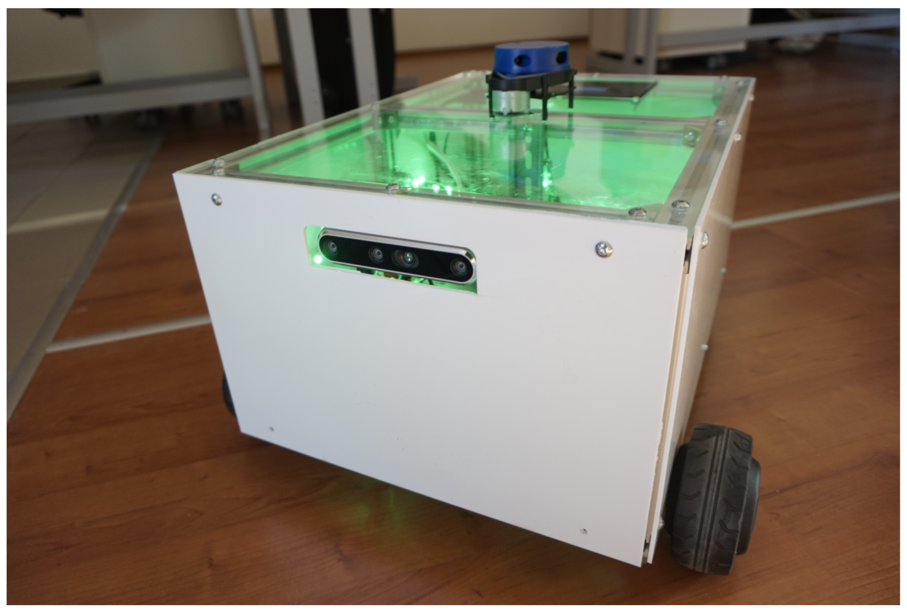
2.2. The PlatypOUs Robot Platform
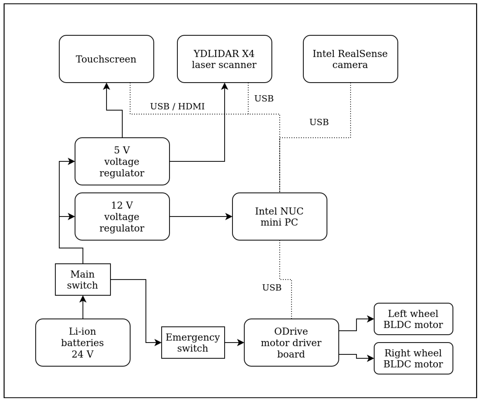
2.2.1. Hardware
2.2.2. Software
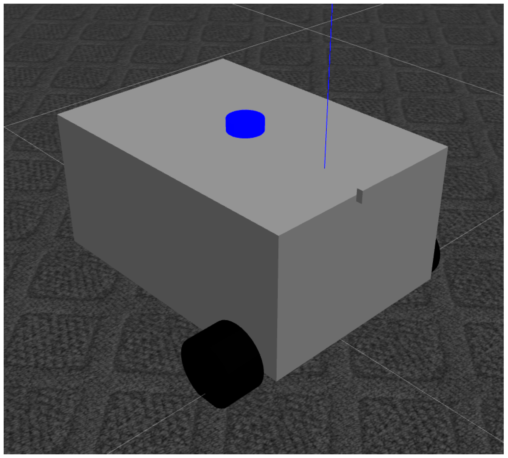
2.2.3. Programming and Simulation Environment
2.3. Data Acquisition and Preprocessing
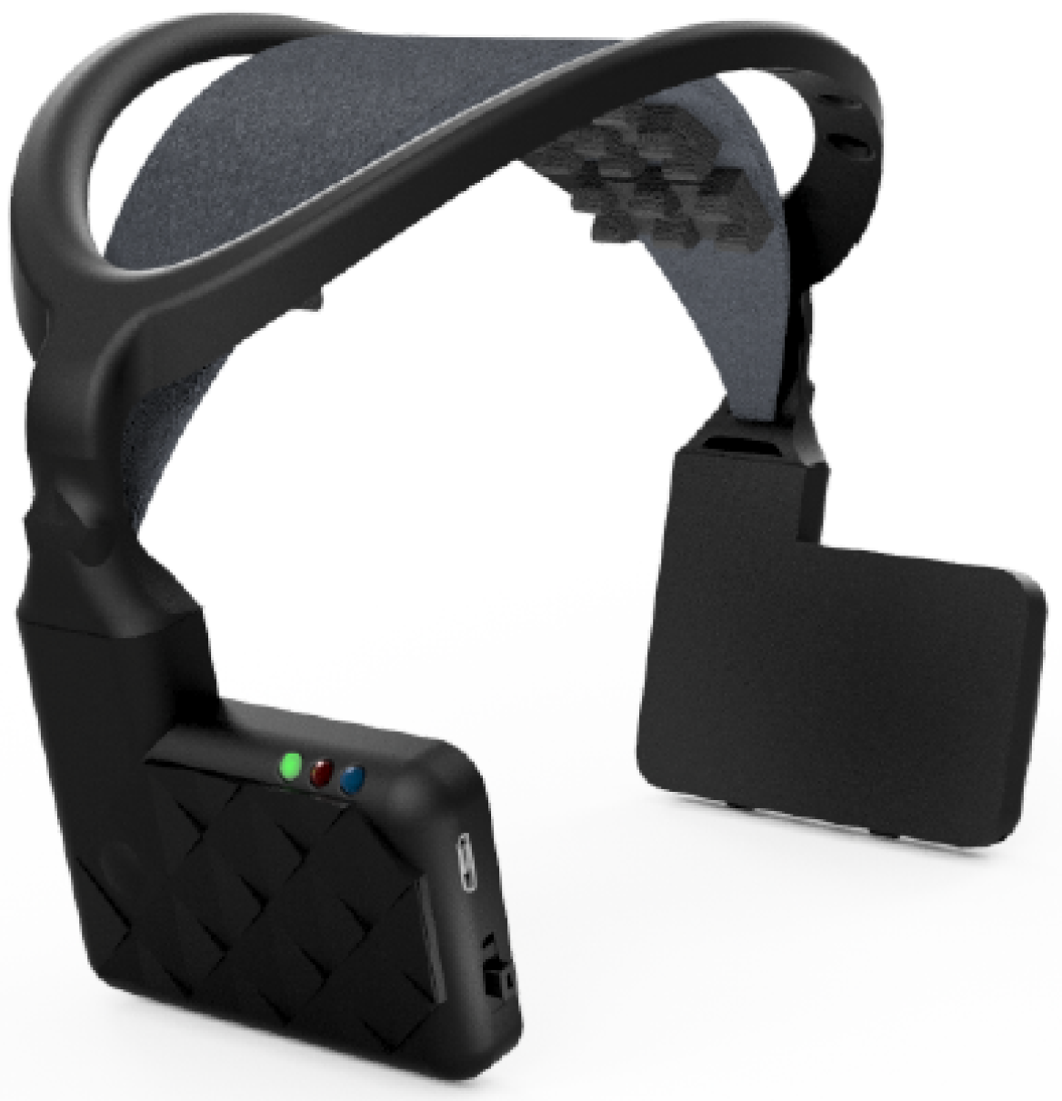
2.3.1. Hardware
2.3.2. Software Tools
2.3.3. Data Acquisition Paradigm
2.3.4. Data Preprocessing
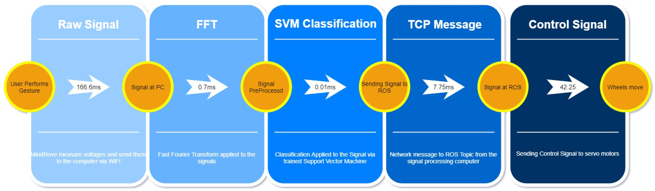
2.3.5. System Response
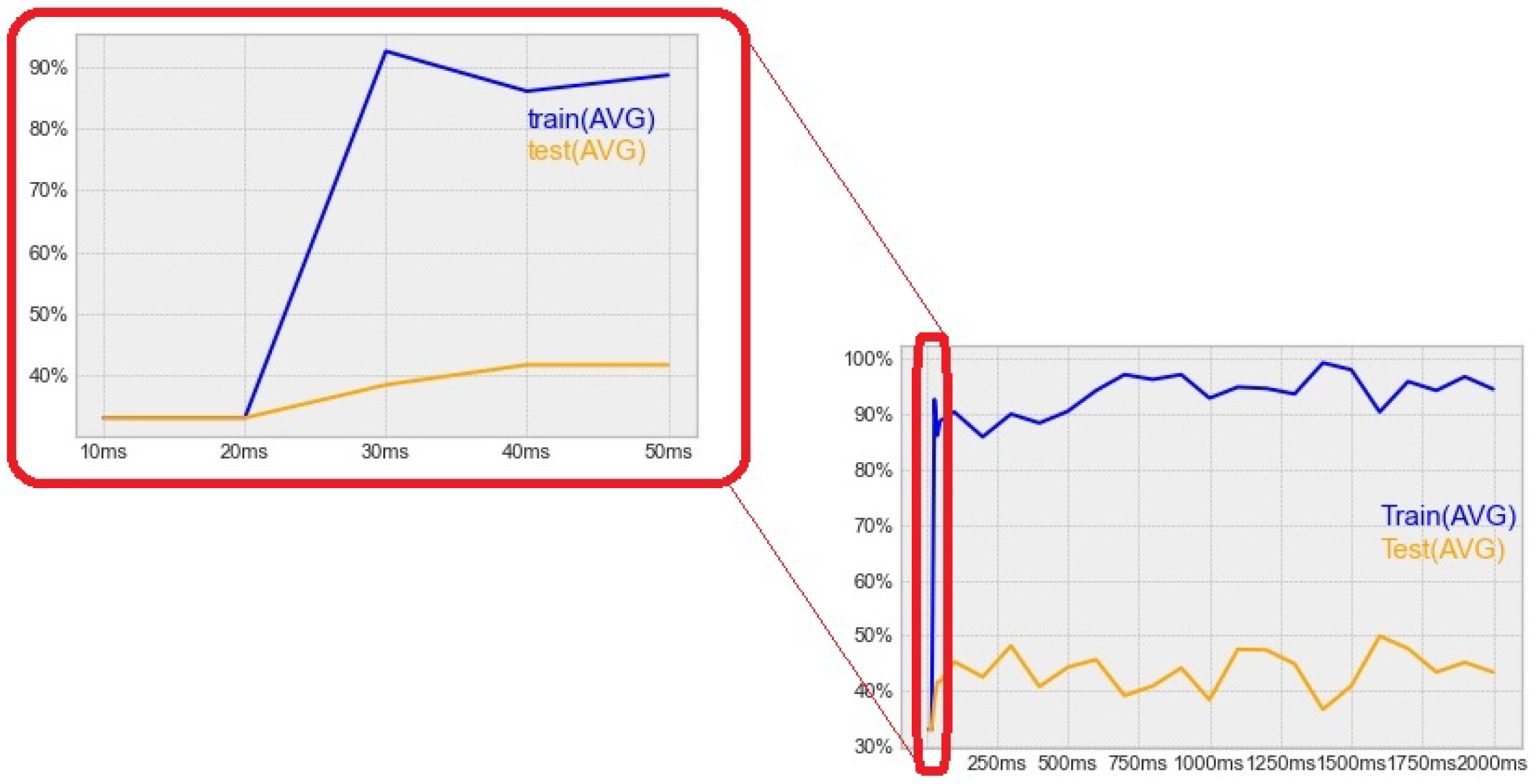
2.3.6. Signal Length
2.4. SVM-Based Classifier
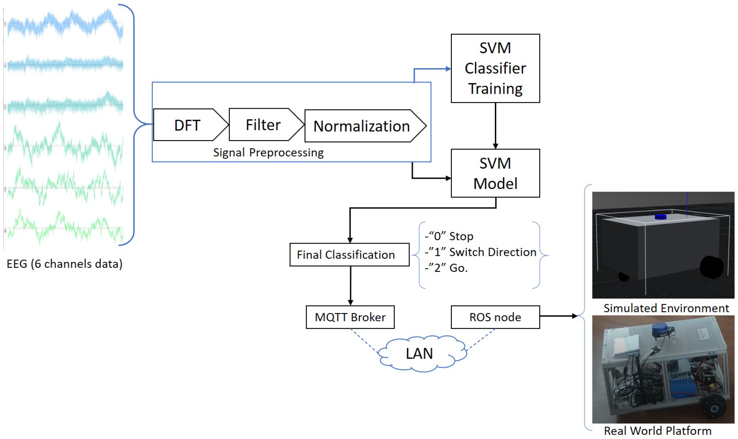
2.5. Finalized EMG-Driven Architecture
- 0—“Stop”
- 1—“Switch direction”
- 2—“Go”
- 0—“Forward”
- 1—“Right”
- 2—“Backwards”
- 3—“Left”
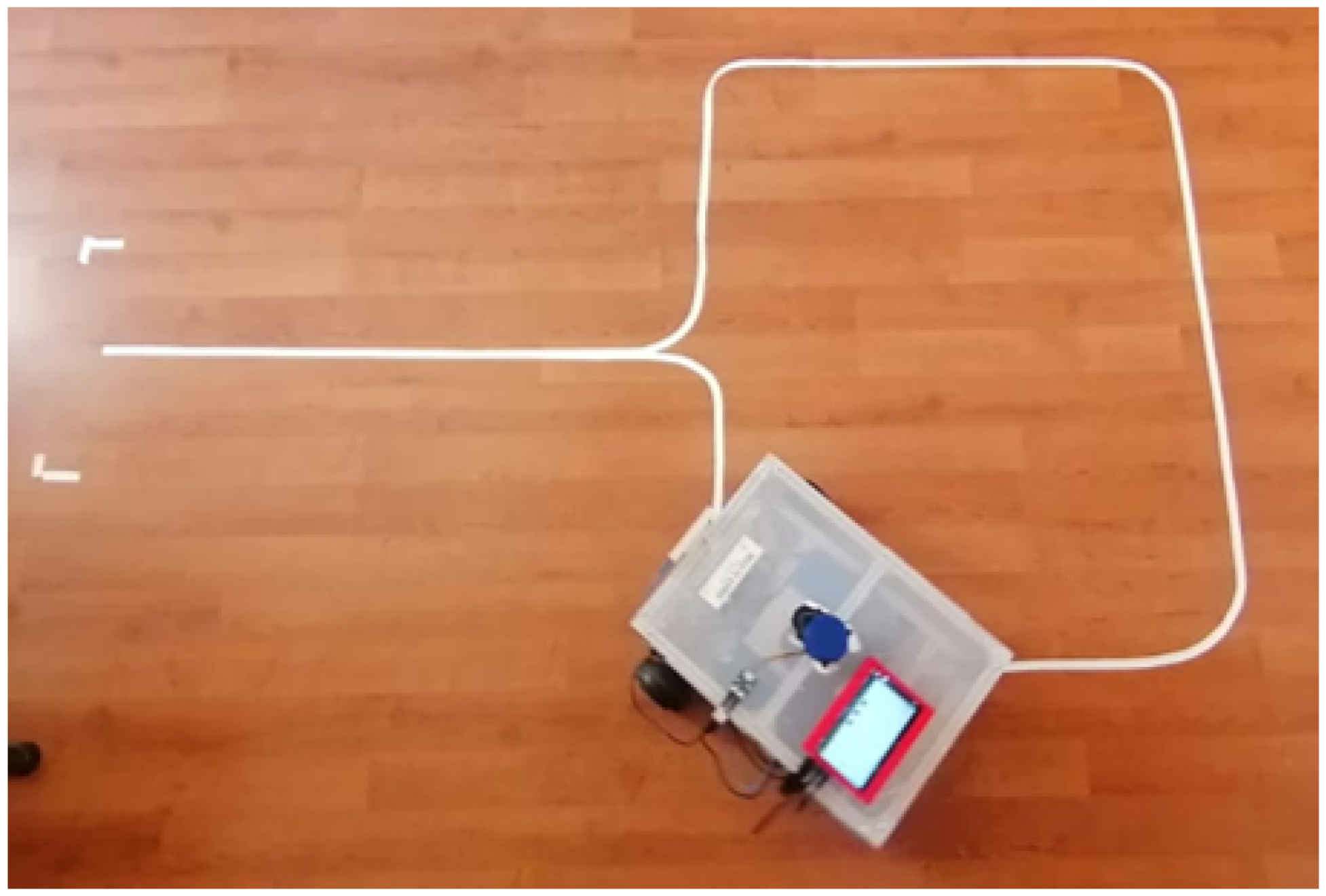
3. Procedure
4. Results
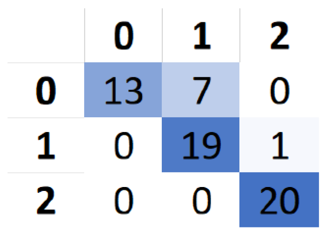
4.1. SVM Classification and Assessment
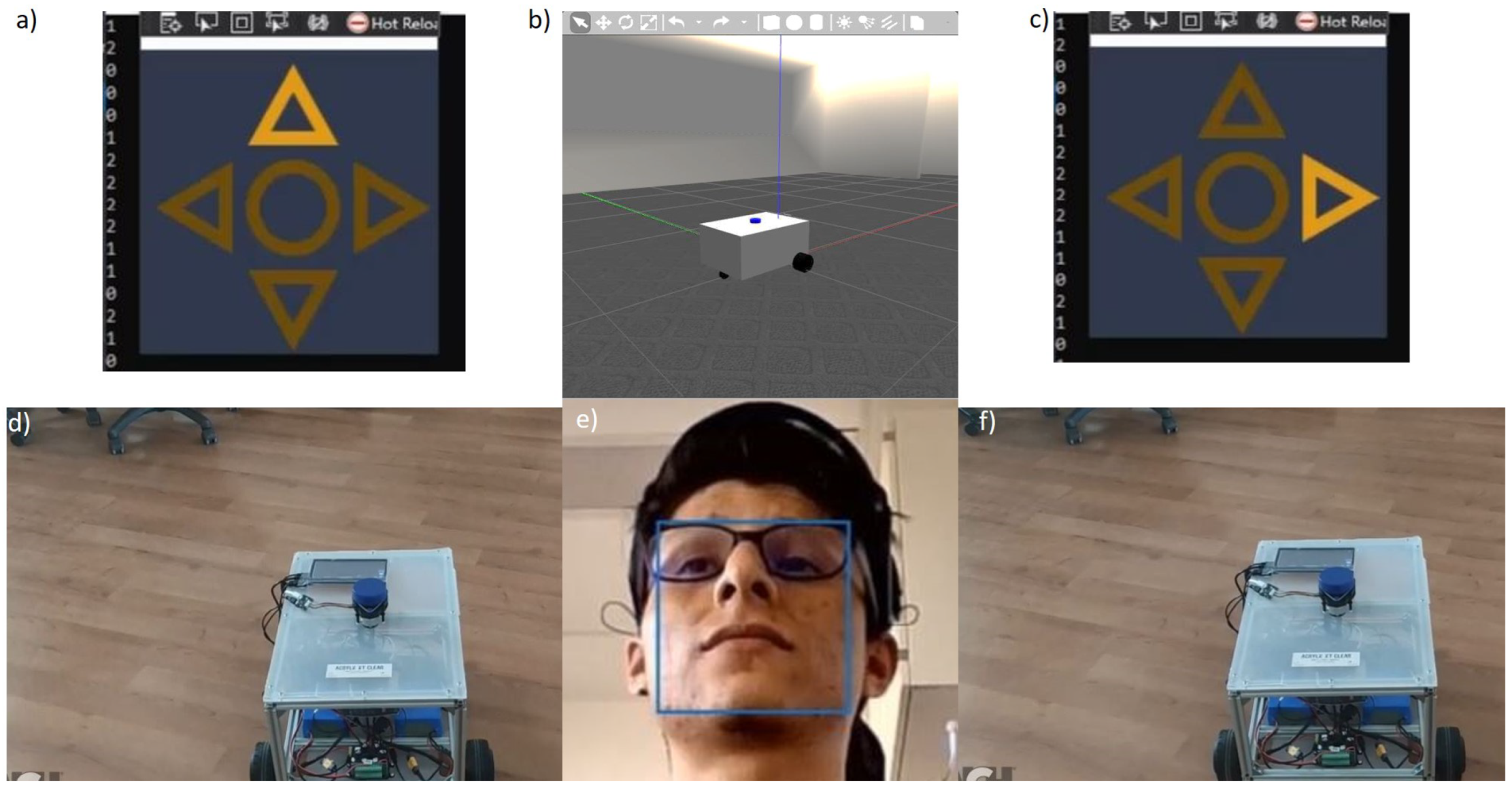
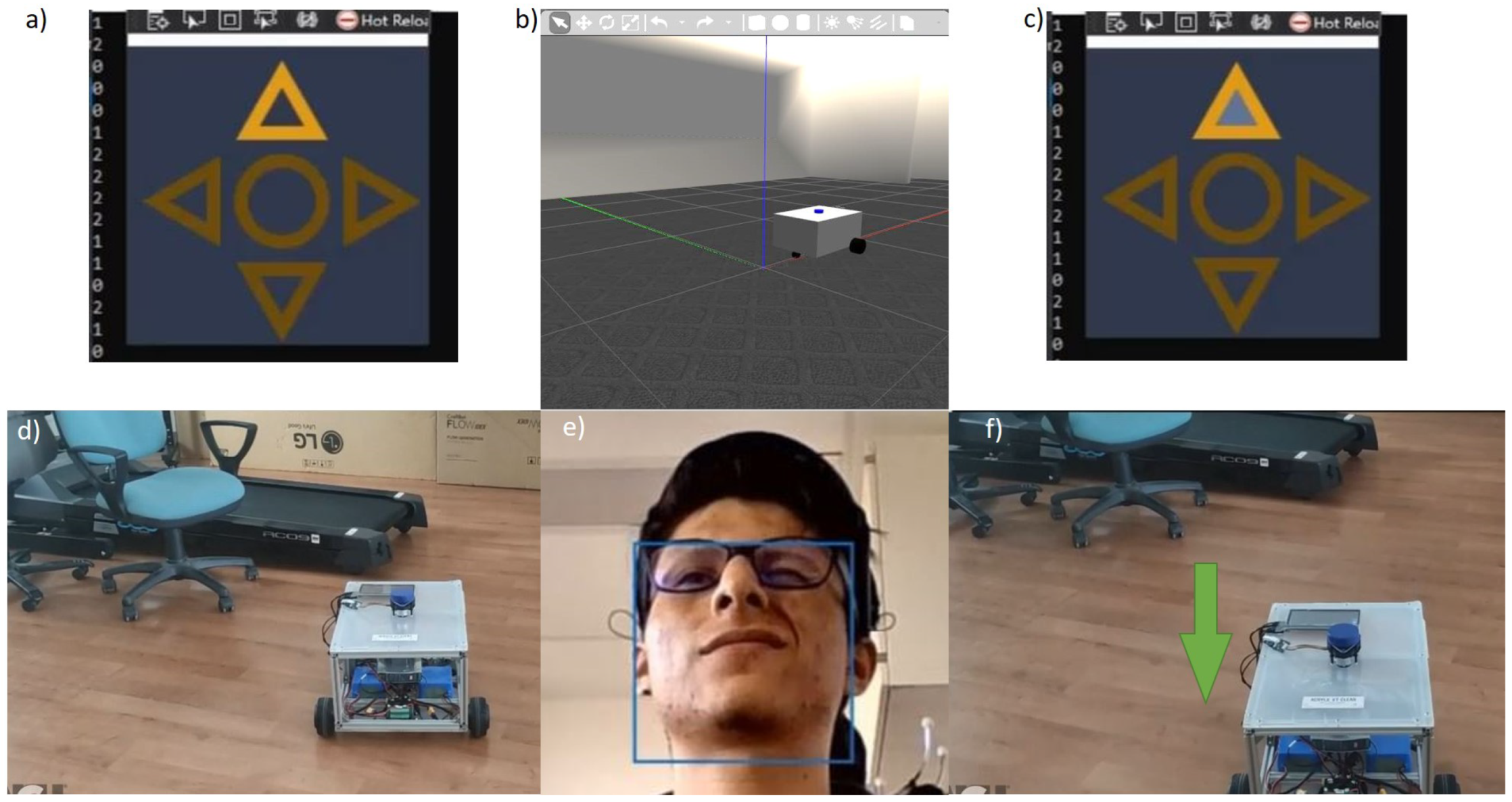
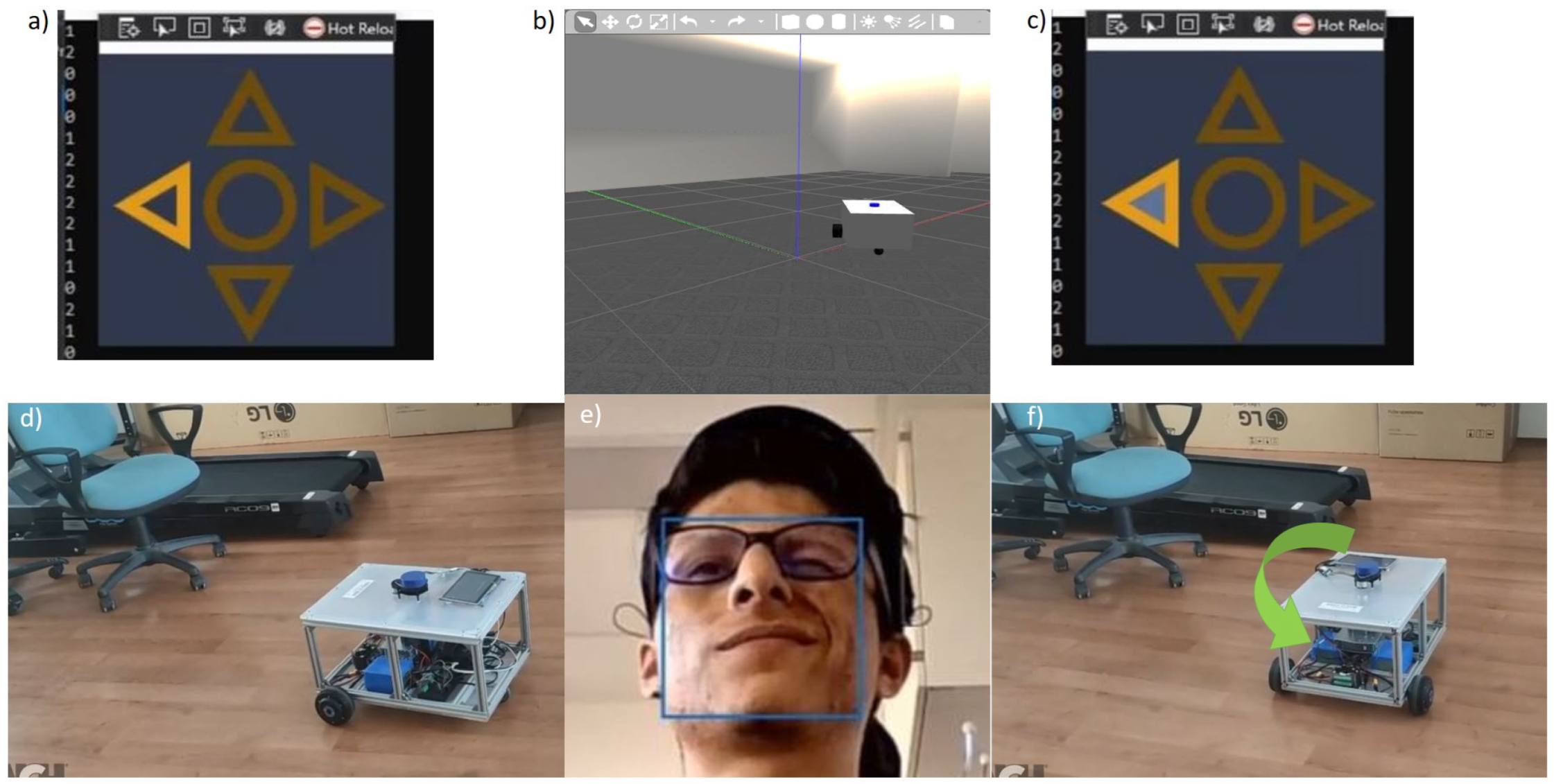
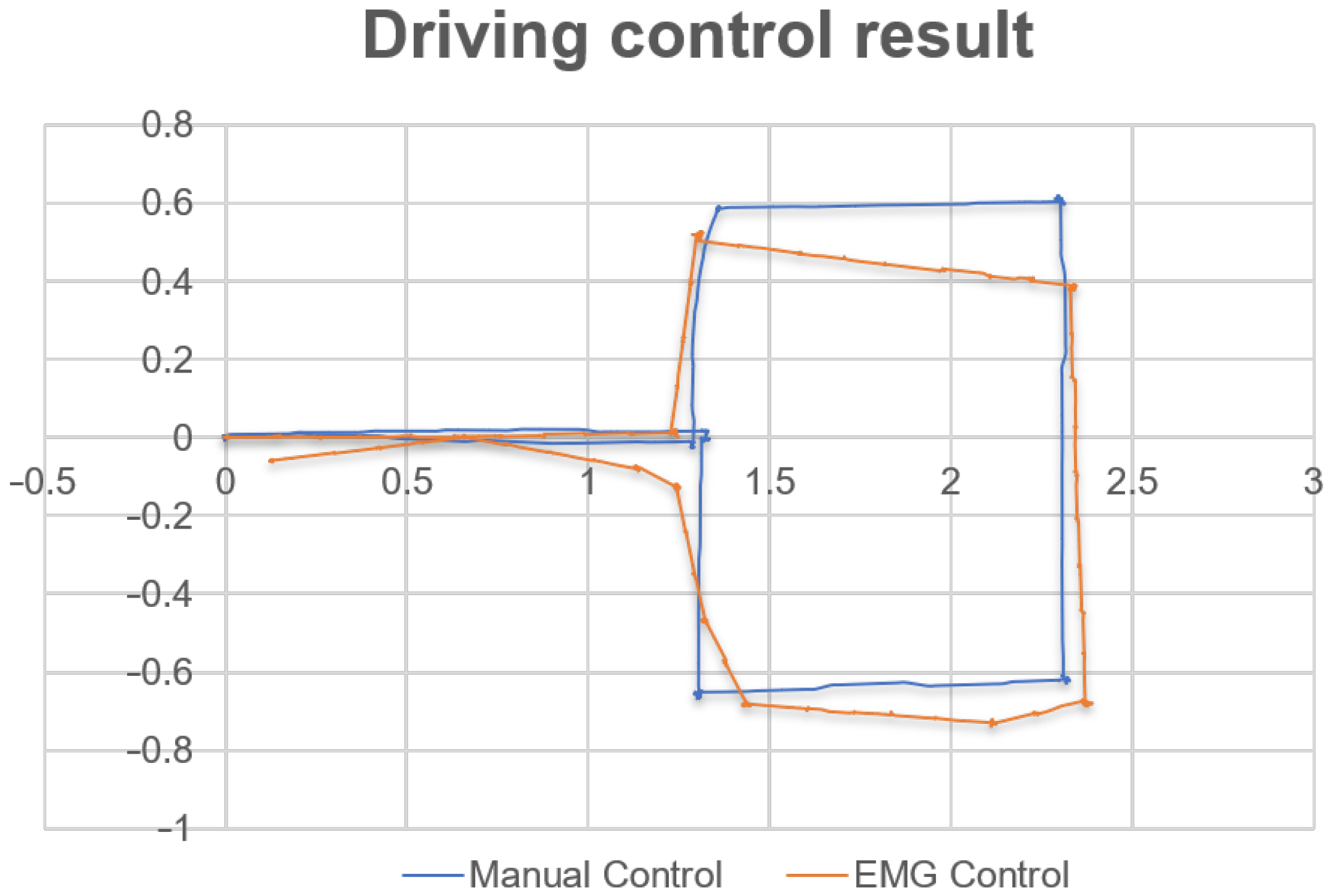
4.2. Robot Control Tests—Real/Virtual
5. Discussion—Limitations and Future Work
6. Conclusions
Author Contributions
Funding
Acknowledgments
Conflicts of Interest
References
- Haidegger, T. Taxonomy and Standards in Robotics. In Encyclopedia of Robotics; Ang, M.H., Khatib, O., Siciliano, B., Eds.; Springer Nature: Berlin/Heidelberg, Germany, 2022; pp. 1–10. [Google Scholar] [CrossRef]
- Haidegger, G.; Paniti, I. Episodes of robotics and manufacturing automation achievements from the past decades and vision for the next decade. Acta Polytech. Hung. J. Appl. Sci. 2019, 16, 119–136. [Google Scholar] [CrossRef]
- Haidegger, T.; Galambos, P.; Rudas, I.J. Robotics 4.0—Are we there yet? In Proceedings of the 2019 IEEE 23rd International Conference on Intelligent Engineering Systems (INES), Gödöllő, Hungary, 25–27 April 2019; pp. 117–124. [Google Scholar]
- Boesl, D.B.; Haidegger, T.; Khamis, A.; Mai, V.; Mörch, C. Automating the Achievement of SDGs: Robotics Enabling & Inhibiting the Accomplishment of the SDGs. 2021. Available online: http://real.mtak.hu/131796/ (accessed on 1 March 2022).
- Haidegger, T. Autonomy for surgical robots: Concepts and paradigms. IEEE Trans. Med Robot. Bionics 2019, 1, 65–76. [Google Scholar] [CrossRef]
- Nagy, T.D.; Haidegger, T. A dvrk-based framework for surgical subtask automation. Acta Polytech. Hung. 2019, 16, 61–78. [Google Scholar]
- Takács, B.; Dóczi, R.; Sütő, B.; Kalló, J.; Várkonyi, T.A.; Haidegger, T.; Kozlovszky, M. Extending AUV response robot capabilities to solve standardized test methods. Acta Polytech. Hung. 2016, 13, 157–170. [Google Scholar]
- Gallacher, C.; Mohtat, A.; Ding, S.; Kövecses, J. Toward open-source portable haptic displays with visual-force-tactile feedback colocation. In Proceedings of the 2016 IEEE Haptics Symposium (HAPTICS), Philadelphia, PA, USA, 8–11 April 2016; pp. 65–71. [Google Scholar]
- Takacs, A.; Eigner, G.; Kovács, L.; Rudas, I.J.; Haidegger, T. Teacher’s kit: Development, usability, and communities of modular robotic kits for classroom education. IEEE Robot. Autom. Mag. 2016, 23, 30–39. [Google Scholar] [CrossRef]
- Khamis, A.; Meng, J.; Wang, J.; Azar, A.T.; Prestes, E.; Li, H.; Hameed, I.A.; Takács, A.; Rudas, I.J.; Haidegger, T. Robotics and Intelligent Systems Against a Pandemic. Acta Polytech. Hung. 2021, 18, 13–35. [Google Scholar] [CrossRef]
- Lalonde, J.F.; Bartley, C.P.; Nourbakhsh, I. Mobile robot programming in education. In Proceedings of the 2006 IEEE International Conference on Robotics and Automation, Orlando, FL, USA, 15–19 May 2006; pp. 345–350. [Google Scholar]
- Ali, W.G. A semi-autonomous mobile robot for education and research. J. King Saud Univ. Eng. Sci. 2011, 23, 131–138. [Google Scholar] [CrossRef] [Green Version]
- Arvin, F.; Espinosa, J.; Bird, B.; West, A.; Watson, S.; Lennox, B. Mona: An Affordable Open-Source Mobile Robot for Education and Research. J. Intell. Robot. Syst. 2019, 94, 761–775. [Google Scholar] [CrossRef] [Green Version]
- Mac, T.T.; Lin, C.Y.; Huan, N.G.; Duc, L.; Nhat, P.C.H.; Hai, H.H. Hybrid SLAM-based Exploration of a Mobile Robot for 3D Scenario Reconstruction and Autonomous Navigation. Acta Polytech. Hung. 2021, 18, 197–212. [Google Scholar]
- Shadrin, G.K.; Alontseva, D.L.; Kussaiyn-Murat, A.T.; Kadyroldina, A.T.; Ospanov, O.B.; Haidegger, T. Application of Compensation Algorithms to Control the Movement of a Robot Manipulator. Acta Polytech. Hung. 2020, 17, 191–214. [Google Scholar] [CrossRef]
- Vega, J.; Cañas, J.M. PiBot: An open low-cost robotic platform with camera for STEM education. Electronics 2018, 7, 430. [Google Scholar] [CrossRef] [Green Version]
- Karim, M.E.; Lemaignan, S.; Mondada, F. A review: Can robots reshape K-12 STEM education? In Proceedings of the 2015 IEEE International Workshop on Advanced Robotics and Its Social Impacts (ARSO), Lyon, France, 30 June–2 July 2015; pp. 1–8. [Google Scholar]
- Tosello, E.; Castaman, N.; Menegatti, E. Using robotics to train students for Industry 4.0. IFAC-PapersOnLine 2019, 52, 153–158. [Google Scholar] [CrossRef]
- Tosello, E.; Castaman, N.; Michieletto, S.; Menegatti, E. Teaching robot programming for industry 4.0. In International Conference EduRobotics 2016; Springer: Berlin/Heidelberg, Germany, 2018; pp. 107–119. [Google Scholar]
- Mai, P.T.; Tick, A. Cyber Security Awareness and behavior of youth in smartphone usage: A comparative study between university students in Hungary and Vietnam. Acta Polytech. Hung 2021, 18, 67–89. [Google Scholar] [CrossRef]
- Meng, J.; Zhang, S.; Bekyo, A.; Olsoe, J.; Baxter, B.; He, B. Noninvasive Electroencephalogram Based Control of a Robotic Arm for Reach and Grasp Tasks. Sci. Rep. 2016, 6, 38565. [Google Scholar] [CrossRef] [PubMed] [Green Version]
- Allison, B.Z.; Neuper, C. Chapter Could Anyone Use a BCI? In Brain-Computer Interfaces; Springer: London, UK, 2010; pp. 35–54. [Google Scholar]
- Volosyak, I.; Rezeika, A.; Benda, M.; Gembler, F.; Stawicki, P. Towards solving of the Illiteracy phenomenon for VEP-based brain-computer interfaces. Biomed. Phys. Eng. Express 2020, 6, 035034. [Google Scholar] [CrossRef]
- Rejani, Y.I.A.; Selvi, S.T. Early Detection of Breast Cancer using SVM Classifier Technique. Int. J. Comput. Sci. Eng. 2009, 1, 127–130. [Google Scholar]
- Banks, A.; Briggs, E.; Borgendale, K.; Gupta, R. MQTT Version 5.0. OASIS Standard. 2019. Available online: https://docs.oasis-open.org/mqtt/mqtt/v5.0/mqtt-v5.0.html (accessed on 1 March 2022).
- Rodrigues, M.; Branco, K.R.L.J.C. Cloud-SPHERE: Towards Secure UAV Service Provision. J. Intell. Robot. Syst. 2020, 97, 249–268. [Google Scholar] [CrossRef]
- Caiza, G.; Garcia, C.A.; Naranjo, J.E.; Garcia, M.V. Flexible robotic teleoperation architecture for intelligent oil fields. Heliyon 2020, 6, e03833. [Google Scholar] [CrossRef]
- Belmonte, L.M.; García, A.S.; Morales, R.; de la Vara, J.L.; López de la Rosa, F.; Fernández-Caballero, A. Feeling of Safety and Comfort towards a Socially Assistive Unmanned Aerial Vehicle That Monitors People in a Virtual Home. Sensors 2021, 21, 908. [Google Scholar] [CrossRef]
- Martínez, A.; Belmonte, L.M.; García, A.S.; Fernández-Caballero, A.; Morales, R. Facial Emotion Recognition from an Unmanned Flying Social Robot for Home Care of Dependent People. Electronics 2021, 10, 868. [Google Scholar] [CrossRef]
- Bouteraa, Y.; Abdallah, I.B.; ElMogy, A.; Ibrahim, A.; Tariq, U.; Ahmad, T. A Fuzzy Logic Architecture for Rehabilitation Robotic Systems. Int. J. Comput. Commun. Control 2020, 15, 1841–9844. [Google Scholar] [CrossRef]
- Yamin, M.I.; Kuswadi, S.; Sukaridhoto, S. Real Performance Evaluation On MQTT and COAP Protocol in Ubiquitous Network Robot Platform (UNRPF) for Disaster Multi-robot Communication. EMITTER Int. J. Eng. Technol. 2018, 6, 369–385. [Google Scholar] [CrossRef]
- Sahadevan, A.; Mathew, D.; Mookathana, J.; Jose, B.A. An Offline Online Strategy for IoT Using MQTT. In Proceedings of the 2017 IEEE 4th International Conference on Cyber Security and Cloud Computing (CSCloud), New York, NY, USA, 26–28 June 2017; pp. 369–373. [Google Scholar]
- Light, R. Mosquitto: Server and client implementation of the MQTT protocol. J. Open Source Softw. 2017, 2, 256. [Google Scholar] [CrossRef]
- ODrive. 2013. Available online: https://odriverobotics.com/ (accessed on 9 December 2021).
- Quigley, M.; Conley, K.; Gerkey, B.; Faust, J.; Foote, T.; Leibs, J.; Wheeler, R.; Ng, A. ROS: An open-source Robot Operating System. ICRA Workshop Open Source Softw. 2009, 3, 1–6. [Google Scholar]
- Merkel, D. Docker: Lightweight linux containers for consistent development and deployment. Linux J. 2014, 2014, 2. [Google Scholar]
- White, R.; Christensen, H. ROS and Docker. In Robot Operating System (ROS); Koubaa, A., Ed.; Springer International Publishing: Cham, Switzerland, 2017; Volume 707, pp. 285–307. [Google Scholar] [CrossRef]
- Koenig, N.; Howard, A. Design and use paradigms for gazebo, an open-source multi-robot simulator. In Proceedings of the 2004 IEEE/RSJ International Conference on Intelligent Robots and Systems, Sendai, Japan, 28 September–2 October 2004; Volume 3, pp. 2149–2154. [Google Scholar]
- MindRove. 2021. Available online: http://mindrove.com (accessed on 9 December 2021).
- MindRove SDK. 2021. Available online: https://github.com/mindrove/sdk_public (accessed on 9 December 2021).
- BrainFlow. BrainFlow Framework. 2021. Available online: https://github.com/brainflow-dev/brainflow (accessed on 9 December 2021).
- EMGU. EMGU CV. 2016. Available online: https://www.emgu.com/wiki/index.php/Main_Page (accessed on 9 December 2021).
- Cortes, C.; Vapnik, V. Support-vector networks. Mach. Learn. 1995, 20, 273–297. [Google Scholar] [CrossRef]
- Hart, S.G. NASA-task load index (NASA-TLX); 20 years later. In Proceedings of the Human Factors and Ergonomics Society Annual Meeting; Sage Publications: Los Angeles, CA, USA, 2006; pp. 904–908. [Google Scholar] [CrossRef] [Green Version]
- Roy, Y.; Banville, H.; Albuquerque, I.; Gramfort, A.; Falk, T.H.; Faubert, J. Deep learning-based electroencephalography analysis: A systematic review. J. Neural Eng. 2019, 16, 051001. [Google Scholar] [CrossRef] [PubMed]
- Hajdu, C.; Hollosi, J.; Krecht, R.; Ballagi, A.; Pozna, C.R. Economical Mobile Robot Design Prototype and Simulation for Industry 4.0 Applications; Institute of Electrical and Electronics Engineers Inc.: Los Alamitos, CA, USA, 2020; pp. 155–160. [Google Scholar] [CrossRef]
- Guyonneau, R.; Mercier, F. IstiABot, an Open Source Mobile Robot for Education and Research. In Proceedings of the 2019 12th International Workshop on Robot Motion and Control (RoMoCo), Poznan, Poland, 8–10 July 2019; pp. 131–136. [Google Scholar] [CrossRef]
- University of Miskolc. Magyarok a Marson. 2021. Available online: http://www.magyarokamarson.hu (accessed on 9 December 2021).
- Hungarian Youth Robot Cup. 2021. Available online: http://pingvin.nyf.hu/robojun/index_a.php (accessed on 9 December 2021).
- WRO2022 COMPETITION. 2021. Available online: https://wro.hu/ (accessed on 9 December 2021).
- Borsa Détár, I. PlatypOUs—Mobile Robot Platform. 2021.


Publisher’s Note: MDPI stays neutral with regard to jurisdictional claims in published maps and institutional affiliations. |
© 2022 by the authors. Licensee MDPI, Basel, Switzerland. This article is an open access article distributed under the terms and conditions of the Creative Commons Attribution (CC BY) license (https://creativecommons.org/licenses/by/4.0/).
Share and Cite
Rácz, M.; Noboa, E.; Détár, B.; Nemes, Á.; Galambos, P.; Szűcs, L.; Márton, G.; Eigner, G.; Haidegger, T. PlatypOUs—A Mobile Robot Platform and Demonstration Tool Supporting STEM Education. Sensors 2022, 22, 2284. https://doi.org/10.3390/s22062284
Rácz M, Noboa E, Détár B, Nemes Á, Galambos P, Szűcs L, Márton G, Eigner G, Haidegger T. PlatypOUs—A Mobile Robot Platform and Demonstration Tool Supporting STEM Education. Sensors. 2022; 22(6):2284. https://doi.org/10.3390/s22062284
Chicago/Turabian StyleRácz, Melinda, Erick Noboa, Borsa Détár, Ádám Nemes, Péter Galambos, László Szűcs, Gergely Márton, György Eigner, and Tamás Haidegger. 2022. "PlatypOUs—A Mobile Robot Platform and Demonstration Tool Supporting STEM Education" Sensors 22, no. 6: 2284. https://doi.org/10.3390/s22062284