
Detail-Preserving Shape Unfolding


1
School of Mathematical Science, Dalian University of Technology, Dalian 116024, China
2
College of Information Science and Technology, Dalian Maritime University, Dalian 116024, China
3
School of Mathematics and Information Science, Nanchang Hangkong University, Nanchang 330031, China
*
Author to whom correspondence should be addressed.
Sensors 2021, 21(4), 1187; https://doi.org/10.3390/s21041187
Submission received: 26 December 2020
/
Revised: 2 February 2021
/
Accepted: 4 February 2021
/
Published: 8 February 2021
(This article belongs to the Section Sensing and Imaging)
Abstract
:Canonical extrinsic representations for non-rigid shapes with different poses are preferable in many computer graphics applications, such as shape correspondence and retrieval. The main reason for this is that they give a pose invariant signature for those jobs, which significantly decreases the difficulty caused by various poses. Existing methods based on multidimentional scaling (MDS) always result in significant geometric distortions. In this paper, we present a novel shape unfolding algorithm, which deforms any given 3D shape into a canonical pose that is invariant to non-rigid transformations. The proposed method can effectively preserve the local structure of a given 3D model with the regularization of local rigid transform energy based on the shape deformation technique, and largely reduce geometric distortion. Our algorithm is quite simple and only needs to solve two linear systems during alternate iteration processes. The computational efficiency of our method can be improved with parallel computation and the robustness is guaranteed with a cascade strategy. Experimental results demonstrate the enhanced efficacy of our algorithm compared with the state-of-the-art methods on 3D shape unfolding.
1. Introduction
The canonical form of 3D shape is very useful for computer graphics applications, such as shape retrieval [1,2,3], shape correspondence [4,5,6] and texture mapping [7,8], as it largely reduces the complexity of 3D shapes caused by various poses. Currently, a popular and commonly used method to obtain canonical forms of 3D shapes is MDS, which comes in classical [9,10], least-squares [11,12,13], and landmark forms [14,15,16,17]. The basic principle of MDS is to maintain the geodesic distances of vertex pairs for the shapes under different poses. To achieve this, it minimizes the sum of squared distance differences between geodesic and Euclidean distances of all vertices pairs on a 3D mesh. However, only satisfying such distance constraints may suffer from serious distortions, leading to a poor accuracy for context-based shape retrieval [3]. A possible way to reduce such distortions is to preserve the local structures of 3D shapes during shape unfolding, that is to make the shape unfolding as rigid as possible [18,19].
In order to preserve as many geometric structures as possible, some researchers tried to obtain feature preserved canonical forms. Most of them first utilized the standard MDS [11] of a shape as guidance, then shape analysis techniques, such as shape deformation based registration [5] or skeleton [20], are applied to prevent distortions with the help of mesh part segmentation [21,22,23]. Recently, Sahillioğlu and Kavan [24] used mass-spring system with non-linear volume constraints to preserve geometric details. Later, Liu et al. [25] introduced an automatic mesh unfolding algorithm by solving a semidefinite programming. The basic idea is to maximize the total variance of the vertex set for a given 3D mesh, while preserving the details by minimizing locally linear reconstruction errors.
However, existing shape unfolding methods have several limitations which hamper their applicability. First, many of them cause significant geometric distortions, as they are the variants of MDS [11], such as the fast MDS [14], non-metric MDS [26] and accelerated MDS [27]. Second, the geodesic distances between all pairs of vertices or landmarks need to be calculated, which is highly time-consuming. Therefore, it is not applicable for high resolution meshes which have hundreds of thousands of vertices. Third, some methods [3,28] have tedious operation processes and their performances highly rely on the accurate execution of each step. Finally, several proposed methods [24,25] need to solve complex non-linear optimization problems which are always time-consuming. In addition, it is difficult to guarantee the robustness of these methods.
Motivated by the above issues, we present a novel mesh unfolding method which has better ability of structure-preserving and ease of use. Our method is based on shape deformation, a technique that can explicitly control the geometric details of meshes. In short, we revisit the mass-spring system model proposed by Sahillioğlu and Kavan [24] and reformulate it in terms of rigid transform energy [19]. Our proposed formulation brings more benefits. Firstly, our model is very simple which only needs to solve linear systems during alternate iteration process. Secondly, it can well preserve the rigidity of the original shape and reduce the geometric distortions as rigid transform energy [19] is considered. Furthermore, our algorithm can be accelerated by using parallel computation and cascade strategy further enhances the robustness of algorithm. In addition, the proposed approach doesn’t need to calculate the pairwise geodesic distances and also has no tedious operation processes, which are timing-consuming and difficult to control.
In summary, the main contributions of our paper are as follows:
- A novel shape unfolding method is proposed for non-rigid 3D mesh based on shape deformation technique. It makes the local deformation be approximately rigid and more details can be preserved.
- The proposed algorithm is easy to implement and parallel computation can be used to improve its computational efficiency. In addition, cascade strategy is used to effectively prevent mesh overstretching.
2. Related Work
While canonical form have been improved greatly for the purpose of context-based shape retrieval or other applications, it still has some issues to a certain degree. In this section, we will briefly describe the research progress of canonical form of 3D shape. These works can be classified into two categories, those with details preservation and without. A recent survey of canonical pose can be found in [29]. Afterwards, as the canonical form is one of the special poses, we also investigate some related work about fabrication and beautification.
2.1. Shape Unfolding without Detail Preservation
Elad and Kimmel [11] took the pairwise geodesic distance as input to generate the coordinates of all vertices that preserved the specified distances. Two strategies were presented in their paper. One was to calculate the centralized squared geodesic distance matrix and then eigen-decomposition was applied to obtain the resulting shape. The other was to produce the result in a least squares sense by using scaling by majorizing a convex function(SMACOF) to minimise the stress [12]. Unlike the least squares MDS method, which matched the resulting Euclidean distances to the exact geodesic distances, Katz et al. [26] only matched the ordering of distances. However, these algorithms are not applicable in practice for meshes with hundreds of thousands as the computation of geodesic distance is timing-consuming.
The fast MDS method [14] and accelerated MDS method [27] were proposed to improve the calculation efficiency of geodesic distance from different views. The former projected the geodesic distance to Euclidean space one dimension at a time and the latter accurately approximated the pairwise geodesic distance maps through farthest point sampling [30]. However, these methods still need to calculate the pairwise geodesic distance. In addition, the results generated by these methods have significant geometric distortions in Euclidean space, which affect the performances of context-based shape retrieval and shape matching. Rustamov [31] used graph Laplacian matrix, which encoded local geometric and topological properties of a mesh, to generate canonical form of 3D shapes. Dan et al. [32] extend the idea of heat kernel signature to robust isometry-invariant volumetric descriptors for shape retrieval. Similar to the classical MDS method [11], eigenvalues and eigenvectors of the Laplacian matrix in these methods were used to obtain the canonical form, which were called as Global Point Signatures. However, they still suffer from serious geometric distortions. In contrast, our approach applies the local rigid energy which effectively avoids this issue.
2.2. Shape Unfolding with Detail Preservation
To preserve more details during shape unfolding, some researchers try to obtain feature-preserving canonical forms. Lian et al. [3] first calculated the standard MDS canonical form for each model. Then the original model was segmented into individual parts by using random walk [21]. Finally, these parts were assembled according to the resulting MDS canonical form. The performance of their method, however, largely depends on the segmentation’s accuracy. Unlike the method proposed by Lian et al. [3], Sahillioğlu [33] utilized volumetric shape deformation technique based on landmarks MDS [15] to preserve initial geometry details. Pickup et al. [28] used the canonical form of mesh skeleton as guidance. They first extracted the curve skeleton [34] from a given model. Then curve skeleton was deformed into a canonical form based on the standard MDS algorithm. Finally, the skeleton driven shape deformation method [20] was used to generate the canonical pose. Nevertheless, the performance of their method depends on the accuracy of skeleton extraction to some extent. In addition, the tedious operation process mentioned above may limit its scope of application in practice.
Some other researchers try to directly obtain the canonical form with details. Pickup et al. [35] calculated the canonical form of a shape by stretching out its limbs. They maximised the Euclidean distances between feature points on the extremities of the mesh while preserving the original edge lengths. Sahillioğlu and Kavan [24] solved this problem by a mass-spring system. This method tried to move each vertex as far away from each other as possible while maintaining the length of finite element. Interior-point method [36] is used to solve their model which is composed of a non-linear objective function and hard volume constrains. In [25], Liu et al. proposed an automatic mesh unfolding method which is solved by semidefinite programming. They first evaluated an approximate pairwise Euclidean distance matrix with unfolding property by maximizing the total variance of the vertex set. Then, the standard MDS or least square MDS [11] was implemented to obtain the final canonical form. However, the above methods only focus on how to preserve edge lengths, but ignore the edge directions of the mesh. In addition, they use sophisticated non-linear optimization algorithm [24,25] which highly affects the applications of their methods. In contrast, our approach imposes constraints on both the edge lengths and directions. Furthermore, the proposed method only needs to solve linear systems and parallel implementation further promotes its practicality.
2.3. Other Special Poses
In this section, we discuss the special poses are generated by other objectives, ranging from beatification to fabrication. Symmetrization, for instance, aims to enhance approximate symmetries of an object by computing optimal displacement vectors that pull the shape towards symmetry through a constrained deformation model [37]. In the animation control application, Ref. [38] proposes a fast approach for optimizing parameters such as spring rest lengths so that the artistically modeled shape represents the equilibrium after the mesh has settled under gravity. Refs. [39,40] solve another static equilibrium equation for hair animation based on physically. Ref. [41] optimizes a object into a balanced pose that makes it stand after 3D printing through iterating between carving and deformation. Inverse design methods [42,43] obtain a special resting pose for 3D printing through deforming the mesh into the desired target shape under specified forces when fabricated. Ref. [44] solves sphere spherical surface parameterization for shapes with arbitrary topology based on the concepts of electrostatics.
3. Technical Details
In this section we will introduce the details of our shape deformation based unfolding algorithm. The input of our algorithm is a tetrahedral mesh denoted as , which has n vertices and m edges. is the set of vertices connected to vertex i. The embedding of is defined by the vertex positions }. Assuming is deformed into that has the same connectivity as and a different geometric embedding }.
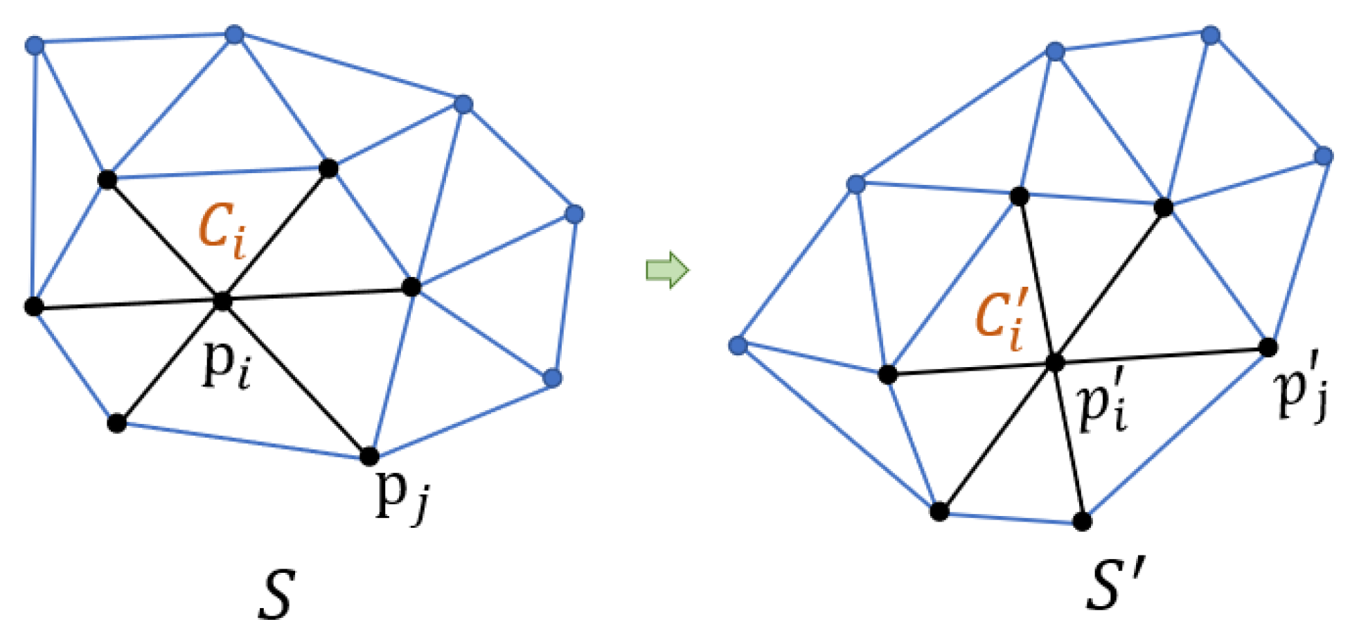
It is natural to define the cells among the topological elements of the mesh. In consideration of the required overlap, we choose a vertex-based definition, where each cell is composed of the edges incident upon a vertex, see Figure 1. Afterwards, we could measure the deviation from rigid transformation between two cells in a least squares sense.
3.1. Rigid Transformation between Two Cells
Given a cell corresponding to vertex i, and its deformed version (see the black lines in Figure 1), the approximated rigid transformation between them is defined by observing the edges emanating from the vertex i in and . If the deformation is rigid between and , then there exists a rotation matrix for all such that
If the deformation is not rigid, in the least squares sense, we still could find the best approximating rotation matrix by minimizing
where, is the per-edge weight. According to [19], the optimal rotation can be easily solved by eigen decomposition. The transformations solved from Equation (2) make sure the local rigidity of is preserved and mesh details can not be discarded.
3.2. Shape Unfolding Model
The proposed shape unfolding model inherits the advantages of mass-spring system. It stretches the distance of non-neighbor vertex pairs on while preserving the rigidity of each cell. Our model can be written in the following form:
where, is a parameter to balance the two items, and are the weights for vertex pairs. Through large experiments, we observe that it obtains satisfactory results when and are set to 1. The influence of will be discussed in Section 4.
In Equation (3), the first item is applied to stretch the non-neighboring vertex pairs as far from each other as possible. The second item is the summation of Equation (2) for all vertex, which is used to promote a rigid local deformation.
By setting , the minimization of Equation (3) is equivalent to minimize the following equation
Equation (4) can be further rewritten into the following matrix form
where, represents the trace of a matrix, , , and constant F are given by
where, is the th row of an identity matrix. Taking the derivative of the unknown and setting the derivative to zero, we can obtain by solving the following linear system [45]
4. Implementation Details
In general, the proposed algorithm can be solved with the following process: given an initial guess , the local rotations are estimated by Equation (2), then are fixed and is obtained by solving Equation (7). The above progress is iteratively performed until an satisfactory solution is generated. This strategy is widely used in computer graphics [19,46]. Our technique can be applied into both triangular mesh and tetrahedral mesh as the data type used in our algorithm is graph structure. However, the representation of tetrahedral mesh obtains the better detail-preserving ability because of the implicit volume constraints. Hence, all experiments are performed on the tetrahedral meshes in our paper. In the following, we will discuss several important parameters used in the optimization.
4.1. Initial Exploration
To evaluate the performance of the proposed method for automatic mesh unfolding, we first discuss the effects of parameter . Intuitively, it affects the local rigidity and the quality of unfolding for a given mesh.
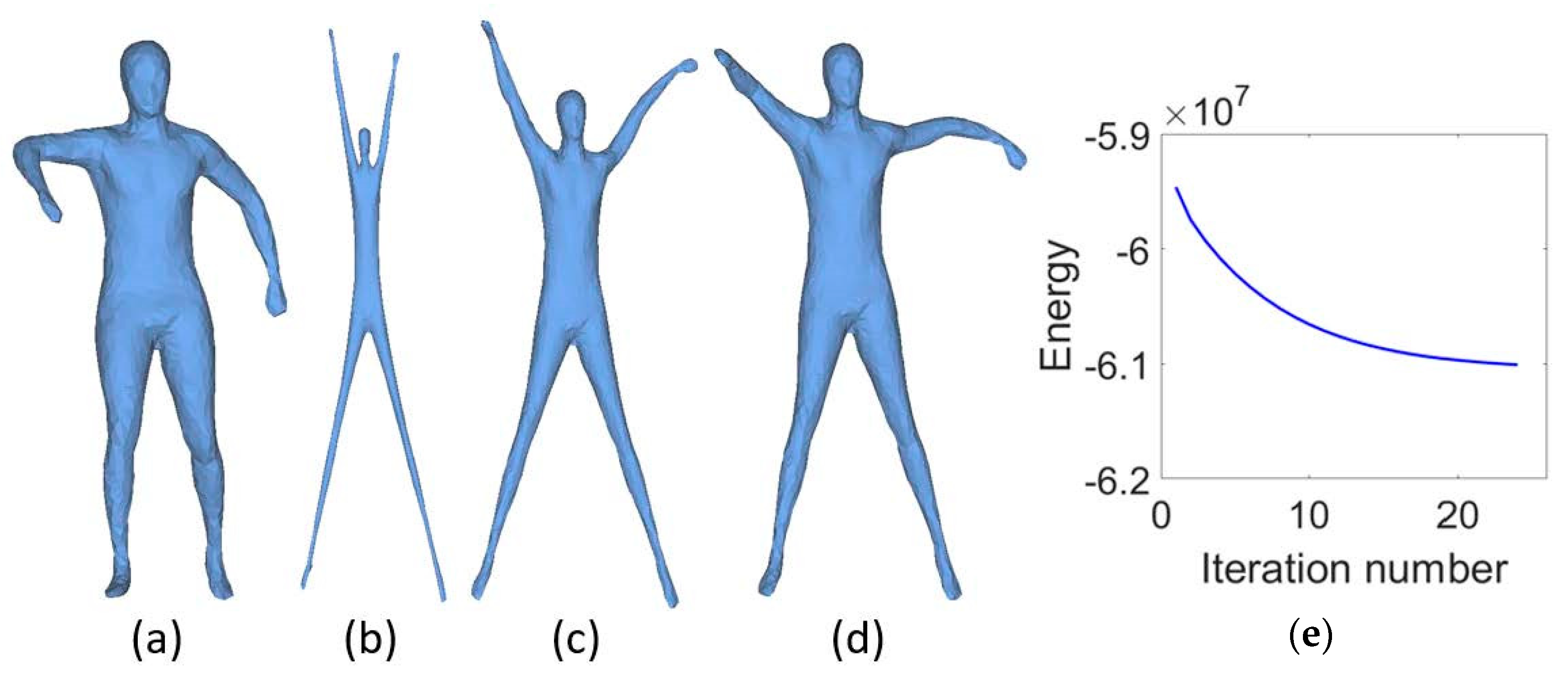
In Figure 2, the Human model (a) is deformed with three different which are 5 × 10, 1 × 10 and 2 × 10, and the corresponding results are shown in (b), (c) and (d) respectively. Each of them are obtained with 25 iterations. From these results we can observe that small helps to stretch the mesh, however many details are lost, while large facilitates the shrinkage of the shape, but it goes against mesh unfolding. The energy curve defined in Equation (3) with = 1 × 10 is shown in Figure 2e. We can clearly see that the energy is almost converged after 15 iterations.
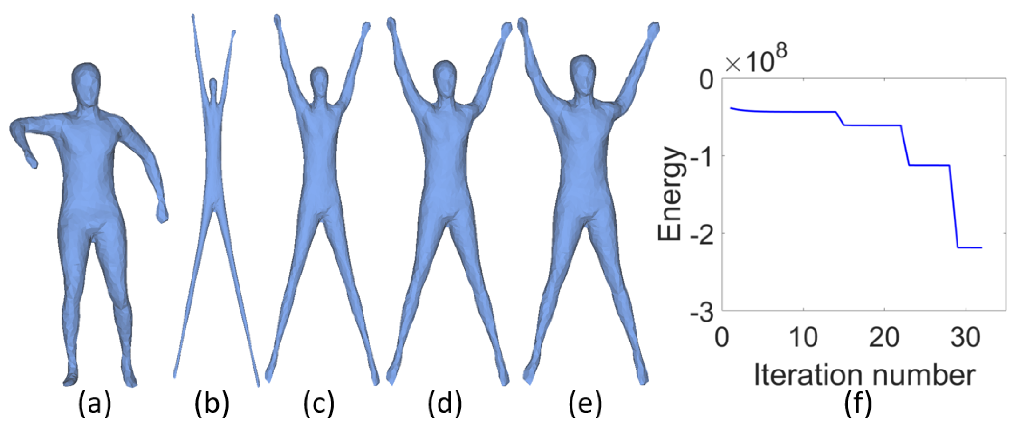
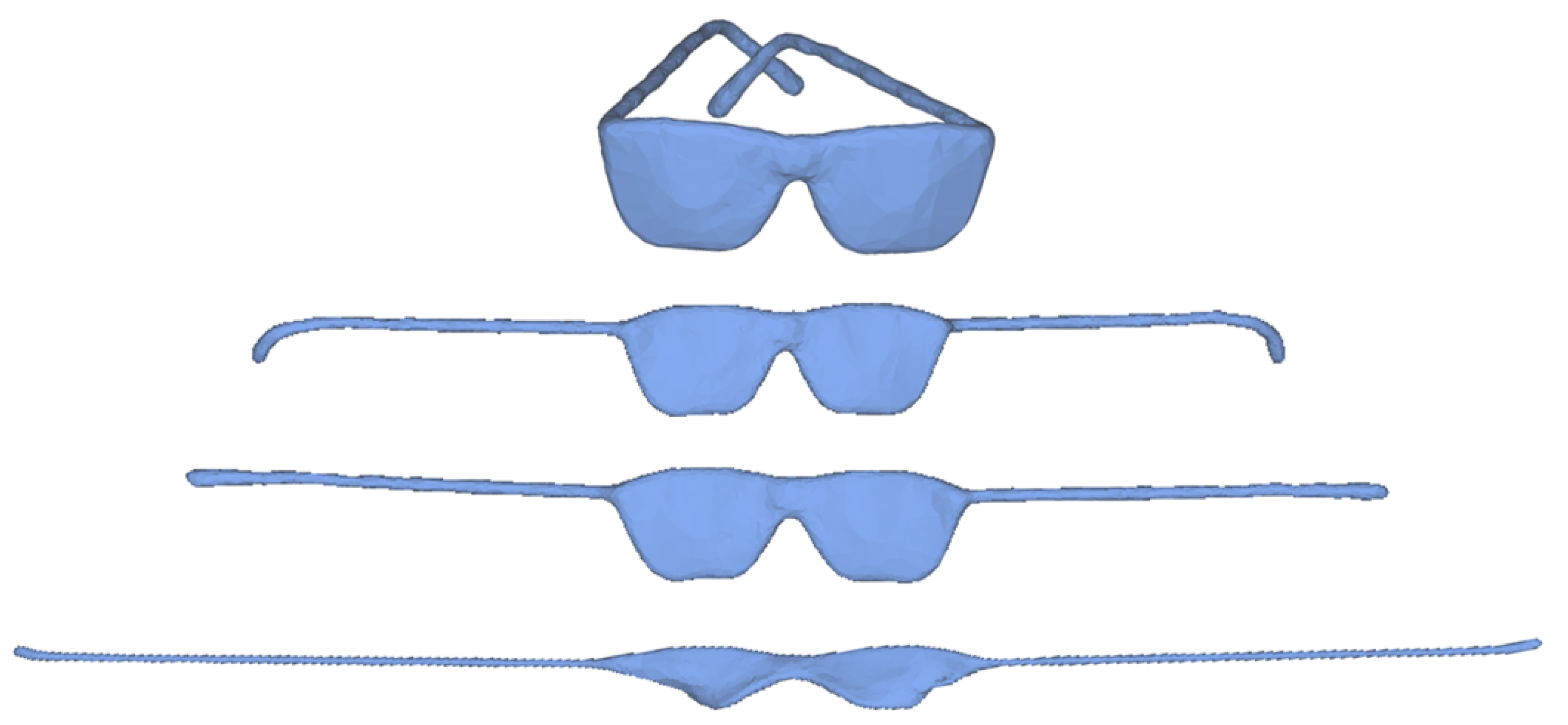
From the above discussion we can conclude that choosing a small results in mesh overstretching in the early iterations and enlarging is a trade-off strategy during iterations. A straightforward strategy is to increase per iteration. But it is difficult to design a universal increasing function for which is suitable for all meshes. Another strategy is to use cascading algorithm with maximum 15 iterations for each cascade. In each cascade, the value of remains the same and it is increased in the next cascade. Figure 3 illustrates the deformed results with cascading algorithm for the same model shown in Figure 2. The shape in (a) is deformed through four cascades with initial = 5 × 10, which is increased two times in each cascade. The corresponding results are shown in (b)–(e) and energy curve is plotted in (f). Experiments demonstrate that the cascading algorithm can obtain better results compared with the fixed value of . However, cascading algorithm costs more extra running time. Fortunately, the computation efficiency of our model can be improved by parallel computation in each cascade. Figure 4 illustrates the influences of different initial . We can obtain a series of unfolding results through tuning parameter , which can meet the different requirements of users.
4.2. Parameters
Through extensive theoretical and numerical analysis we finally adopt the following strategies. Each cascade is stopped when it reaches a specified iteration number or the ratio of energy between adjacent iterations below a given precision. In detail, the initial energy can be calculated by setting , the initial = 5 × 10 for most meshes, enlarging the initial is a good try if the result is not satisfactory, the maximum iterations for each cascade , the precision and the maximum number of cascade . In addition, if the ratio , we also terminate the iteration. Here and are the lengths of the th edge on the intermediate and original tetrahedral mesh respectively.
Pseudo code of our shape unfolding algorithm is shown in Algorithm 1.
| Algorithm 1 Shape unfolding cascading algorithm |
Input: Original tetrahedral mesh , original edge lengths , initial energy , initial , the maximum cascading number , the maximum iterations for each cascade and the precision . Output: Deformed tetrahedral mesh .
|
5. Experimental Details
The proposed mesh unfolding method is tested on a non-rigid 3D watertight meshes dataset [47]. This dataset provides a wide range of non-rigid shape classes. Each class contains 20 different poses and each mesh has about 9500 vertices. To improve the computational efficiency, each mesh is first simplified to about 2000 vertices. Then we use tetgen [48] or [49] to generate the corresponding tetrahedral meshes. We obtain about 513 tetrahedral meshes after removing the failed generation. All experiments are performed on a laptop with Intel Core CPU and 32 G RAM.
5.1. Quantitative Metrics
To demonstrate the effectiveness of the proposed mesh unfolding method, we quantitatively evaluate the quality of the resulting canonical poses. Specifically, the metrics are defined as
and
where, measures the accuracy of the local rigid approximation, measures the mesh stretching between the initial mesh and the canonical pose, and are the Euclidean distances between vertex pairs on the deformed and original mesh. From Equations (8) and (9) we can clearly see that an embedding with small and large will have good rigidity and strong stretching ability, respectively.
In addition, we also use the following metric to measure the similarity between the pairwise Euclidean distances and the corresponding geodesic distances at the deformed canonical mesh:
where, is the pairwise Euclidean distance and is the corresponding geodesic distance. For each mesh, its value close to 0 imply a good geodesic approximation as the difference is taken between unit matrices. Based on the Equations (8)–(10), we can use the empirical cumulative distribution function (CDF) to evaluate the performance of different algorithms on a whole dataset.
5.2. Comparisons
In this section, we compare the results generated by our approach with the state-of-the-art methods: the least squares multidimensional scaling method [11] (LSMDS), skeleton based canonical form [28] (SCF), and detail-preserving mesh unfolding [24] (DPMU). Note that, the method proposed by Liu et al. [25] is not included in our comparisons because of its expensive time consuming, which is 20 times slower than DPMU, and its retrieval accuracy is not the best among the above three methods in the similar dataset [50] from the recent survey paper [29]. To conduct fair comparisons, LSMDS [11] is modified to accept tetrahedral mesh as input and the weights for all vertex pairs are set as 1. For the other methods, all parameters are the same as described in their articles.
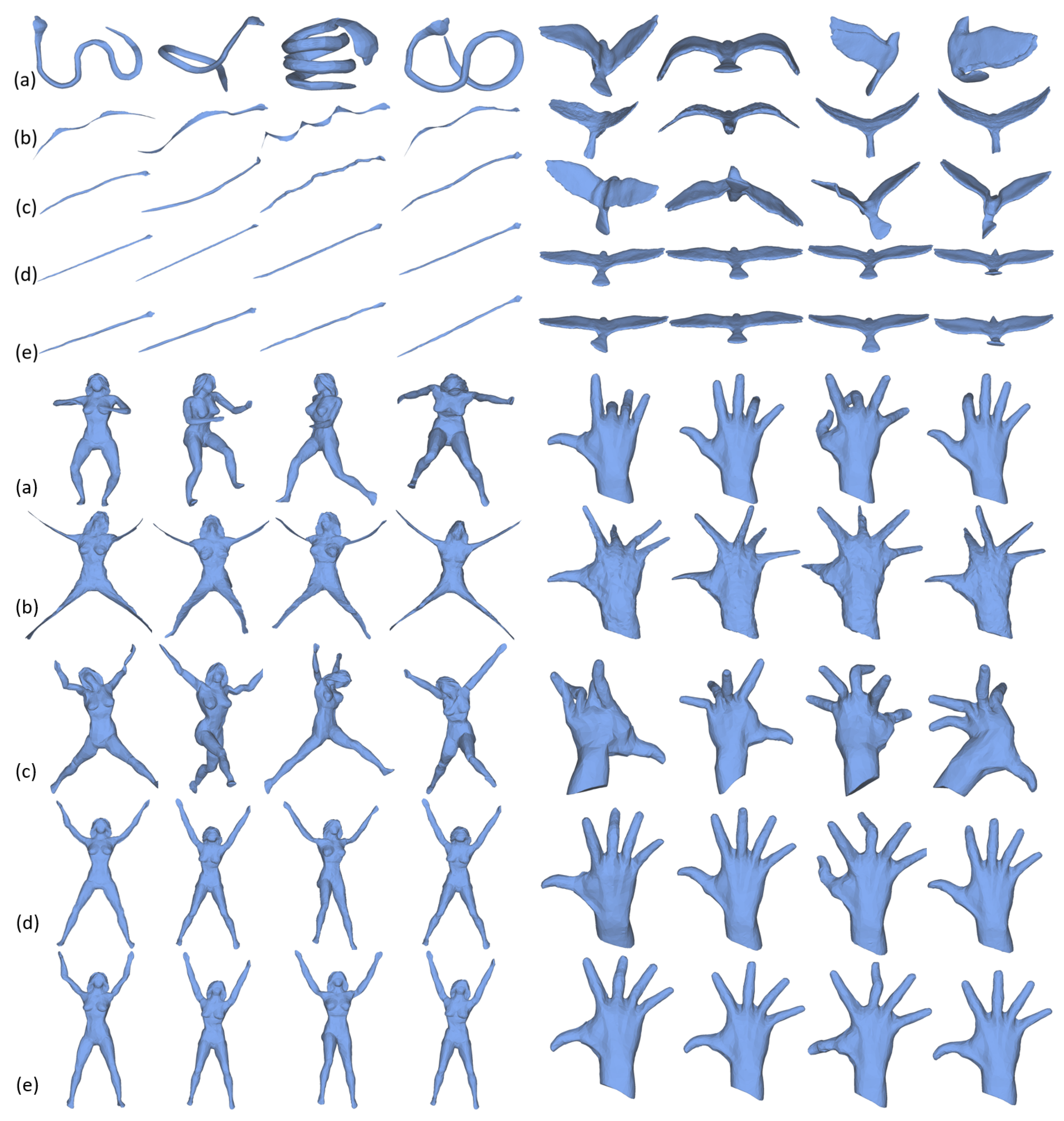
In Figure 5, we illustrate the comparison results among our method, LSMDS, SCF and DPMU. We can observe from this figure that LSMDS always loses some local details of the original meshes, especially for the models with limbs and end-points. While SCF can preserve more details than LSMDS, its efficacy highly depends on the the quality of the skeletal structure which is sensitive to geometry and topology of the mesh. For instance, it is always difficult to extract the accurate skeleton for hand and bird models. As a result, SCF cannot obtain satisfactory results for these meshes. DPMU and our method generate satisfactory results for almost all models. However, our method explicitly preserve the rigidity of the original mesh.
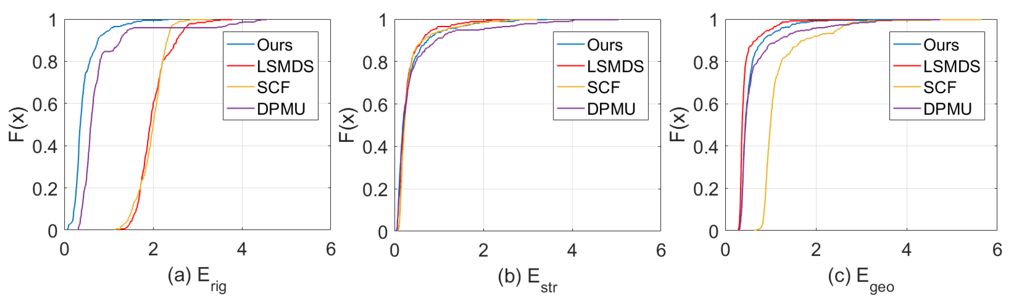
Figure 6 shows the CDF curves of , and for different methods on the dataset [47]. For local rigidity (a), less then 50% samples locate in [0, 2] for LSMDF and SCF methods, and about 95% samples locate in that interval for DPMU, while almost all samples locate in that interval for our method. From (b), we can see that all methods can achieve very similar performances on mesh stretching. In (c), LSMDS can achieve the best performance on geodesic distance preservation, as they consider geodesic distance as hard constraints. However, it is hard to keep the local details. DPMU and our approach have the similar accuracy on this metric and SCF is the worst one. In conclusion, our method is the best for rigid transformation while keeping good performance on and . Similar results also can be found in Table 1. The difference is that they are calculated on the same category.
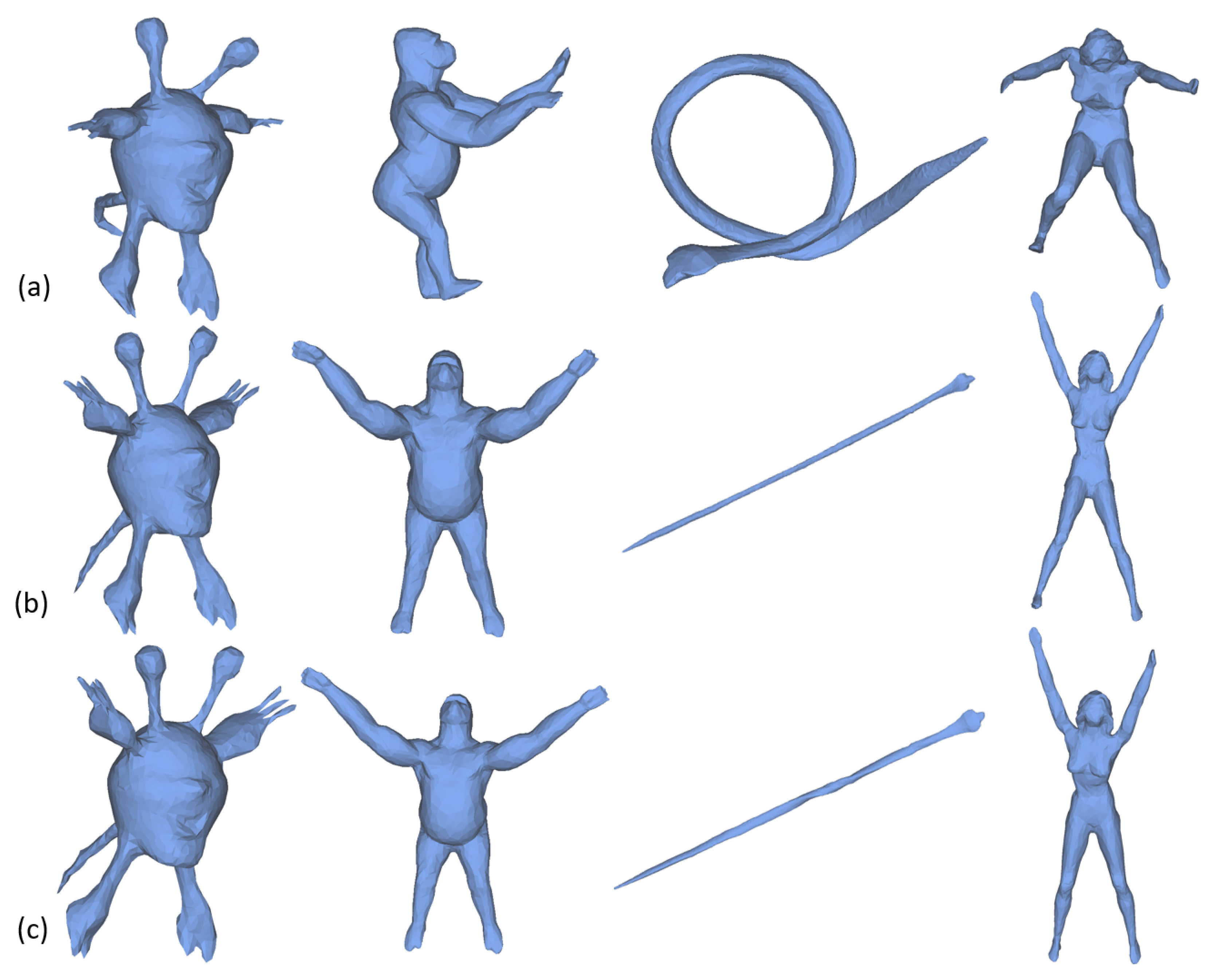
DPMU uses local volume of each vertex as constraint which is nonlinear and the resulting optimization is difficult to solve while the proposed algorithm only needs to solve two simple linear optimization sub-problems. Therefore, our algorithm is faster than DPMU. To prove this, four different shapes are selected and the corresponding unfolding results are shown in Figure 7. In Table 2, we list the running time of our method and DPMU for these shapes. It is clear see from the third and fourth rows that our method consumes less running time for all shapes. In addition, the computational efficiency of our method can be further improved with parallel computation. The last row of Table 2 lists the running time of our method with parallel computation. Note that, the time consumed by the pre-processing process, such as the computation of simplification and tetrahedral mesh which takes about 1.32 s for a shape on the dataset [47], is not taken into account.
5.3. Application to Shape Retrieval
In this section, our algorithm is evaluated on non-rigid shape retrieval application [51,52] and compared with the state-of-the-art methods. Two 3D shape retrieval algorithms, which are based on the mean squares error of vertex positions after using optimal rigid transformation (ORT) [53] and the Clock Matching Bag-of-Features (CMBOF) [2], on the original shapes and the unfolding shapes obtained by LSMDS, SCF, DPMU, and Ours. For each strategy, we first centre the mesh, normalize its scale and use a combination of principal component analysis (PCA) [54] and rectilinearity [55] to normalize its orientation. Then, a similarity matrix is saved for online searching based on some statistical measures. We use nearest neighbors (NN) [56] for evaluation in this paper, which calculates the percentage of the closest retrieved shapes that belong to the same class as the query.
Table 3 lists the retrieval accuracy of NN for different methods. From this comparison we can see that our algorithm can achieve comparable shape retrieval performance among the state-of-the-art shape unfolding methods. It is worth noting that only using 3D rigid transformations (ORT) could achieves high accuracy, which is more than 89.5% for all methods. This demonstrates the efficacy of canonical form in shape retrieval.
6. Integration with User Control
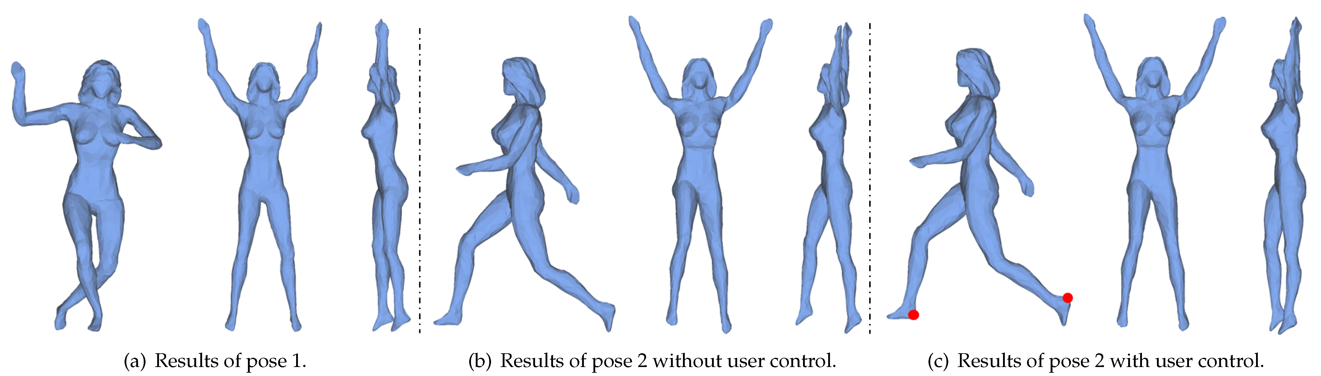
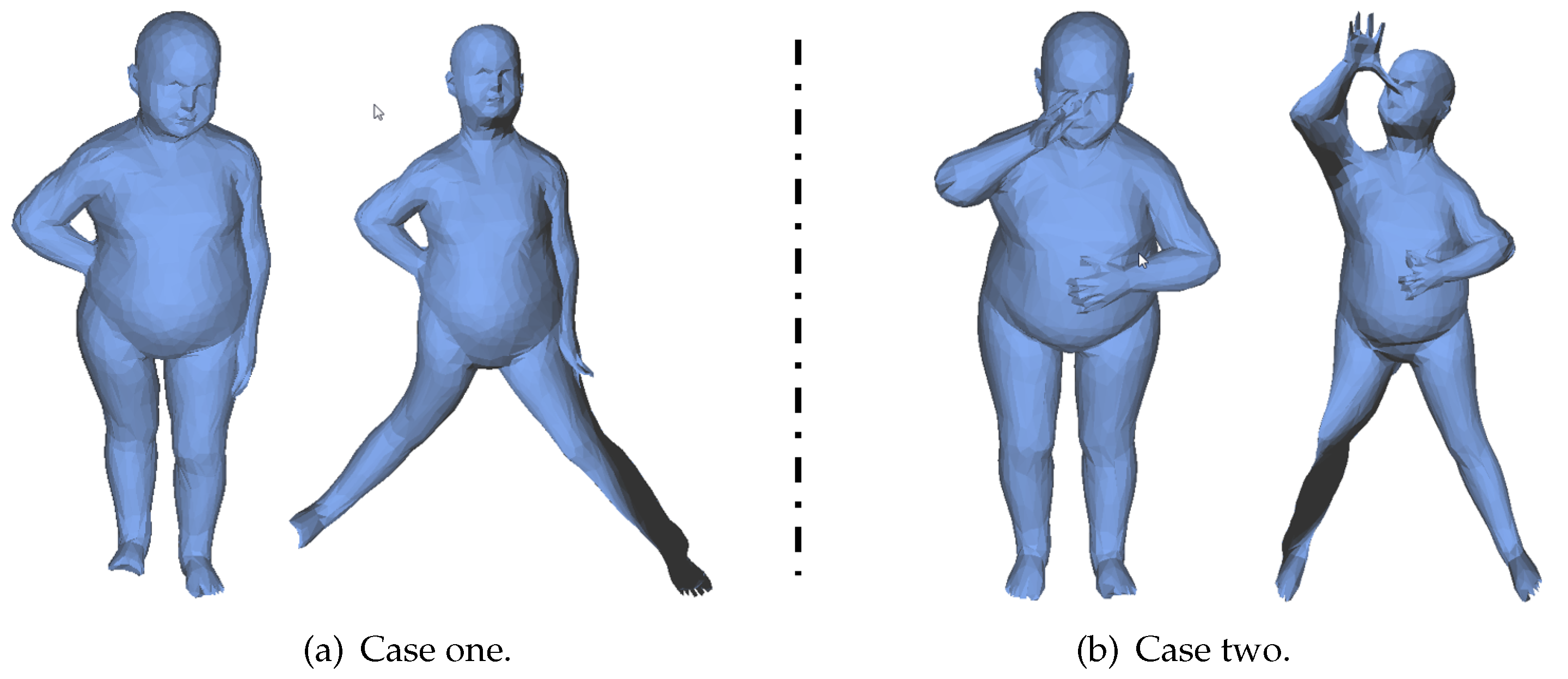
While our algorithm works well on a large number of models, it is difficult to generate highly uniform canonical forms for models with very different poses. In Figure 8, (a)-left and (b)-left are two poses of the same person. After mesh unfolding, their legs (a)-right and (b)-right have different poses. To solve this problem, an extra item is added in Equation (3) to consider the information provided by users.
where, is a parameter to balance the user information, is the weight for vertex pairs, which is also set to 1, is the control set of vertex pairs and is the control vector specified by user.
We find that parameter has a similar role to in experiments, so we set in our algorithm with user control.
In Figure 8, an example is given to show how to specify vertex pairs and control vectors by users. As shown in Figure 8c-left, we first pick one point pair and on the feet (red nodes), then specify their direction and the length after unfolding with the following strategy. As the intrinsic symmetry plane of this model is perpendicular to z-axis, that is , we restrict to be parallel to and the length after unfolding to be . The result after solving Formulation (11) is shown in Figure 8c-right which almost has the same pose as the one in Figure 8a-right.
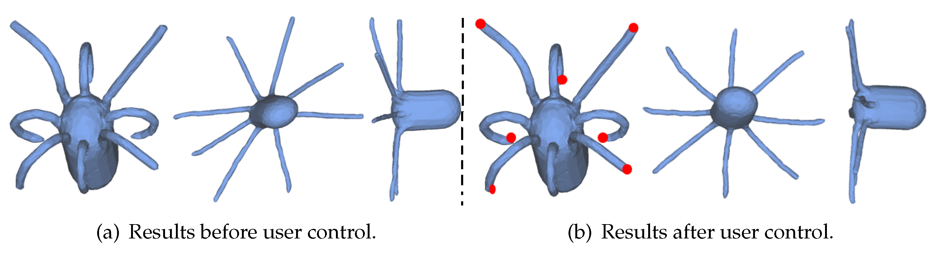
For the Octopus model shown in Figure 9, our method can give a satisfactory result ((a)-middle). However, its tentacles do not in a plane when viewed from another view ((a)-right). Our algorithm with user control can be used to further improve the quality of the canonical form. We first pick one point at the end of each antenna (red points in (b)-left). Then the directions and lengths between the adjacent antennas are restricted to approximate a regular octagon. The resting results are shown in Figure 9b. We can clearly see that all tentacles are almost in the same plane.
7. Conclusions
In this paper, we proposed a novel 3D mesh canonical form generation algorithm based on shape deformation technique. Through extensive experiments, we can see that our method can well preserve the local rigidity of original mesh while unfolding. The non-rigid shape retrieval performance of our method is comparable with the state-of-the-art method. Meanwhile, the proposed algorithm is very simple and easy to implement whose computational performance can be further improved with parallel computation and cascade strategy further enhances the robustness of algorithm. In addition, constraints specified by users can be easily integrated into our approach to further improve the quality of the canonical forms.
Despite those advantages, the proposed canonical method can not deal with the meshes with topological errors [50,57], where parts of the meshes have been incorrectly fused together or have different genus numbers. As shown in Figure 10, our algorithm unfolds the legs successfully, but the adhesion remains unchanged. In these cases, we may need to manually cut the adhesion parts and then perform our shape unfolding algorithm. In addition, how to choose an adaptive will be explored in our future work.
8. Patents
This section is not mandatory, but may be added if there are patents resulting from the work reported in this manuscript.
Author Contributions
Conceptualization, X.L.; methodology, B.L. (Bin Liu); software, J.Z.; validation, W.W., B.L. (Bo Li) and X.L.; formal analysis, B.L. (Bin Liu); investigation, W.W.; resources, J.Z.; data curation, B.L. (Bin Liu) and W.W.; writing—original draft preparation, B.L. (Bin Liu); writing—review and editing, W.W.; visualization, B.L. (Bo Li); supervision, X.L.; project administration, B.L. (Bin Liu); funding acquisition, Weiming Wang, B.L. (Bo Li) and X.L. All authors have read and agreed to the published version of the manuscript.
Funding
This work was supported by the Natural Science Foundations of China (61976040, 61702079, 61762064) and Jiangxi Science Fund for Distinguished Young Scholars (20192BCBL23001).
Institutional Review Board Statement
Not applicable.
Informed Consent Statement
Not applicable.
Data Availability Statement
The data presented in this study are available on request from the corresponding author.
Acknowledgments
The authors would like to thank the valuable comment given by Charlie. C.L. Wang in private communications from the University of Manchester.
Conflicts of Interest
The authors declare no conflict of interest.
References
- Tangelder, J.W.; Veltkamp, R.C. A survey of content based 3D shape retrieval methods. In Proceedings of the Shape Modeling Applications, Genova, Italy, 7–9 June 2004; pp. 145–156. [Google Scholar]
- Lian, Z.; Godil, A.; Sun, X.; Xiao, J. CM-BOF: Visual similarity-based 3D shape retrieval using Clock Matching and Bag-of-Features. Mach. Vis. Appl. 2013, 24, 1685–1704. [Google Scholar] [CrossRef]
- Lian, Z.; Godil, A.; Xiao, J. Feature-Preserved 3D Canonical Form; Kluwer Academic Publishers: Dordrecht, The Netherlands, 2013; pp. 221–238. [Google Scholar]
- Jain, V.; Zhang, H. Robust 3D Shape Correspondence in the Spectral Domain. In Proceedings of the IEEE International Conference on Shape Modeling and Applications, Matsushima, Japan, 14–16 June 2006; p. 19. [Google Scholar]
- Li, S.M.; Wang, C.C.L.; Hui, K.C. Bending-Invariant Correspondence Matching on 3D Human Bodies for Feature Point Extraction. IEEE Trans. Autom. Sci. Eng. 2011, 8, 805–814. [Google Scholar] [CrossRef]
- Sahillioğlu, Y.; Yemez, Y. Minimum-Distortion Isometric Shape Correspondence Using EM Algorithm. IEEE Trans. Pattern Anal. Mach. Intell. 2012, 34, 2203–2215. [Google Scholar] [CrossRef]
- Zigelman, G.; Kimmel, R.; Kiryati, N. Texture mapping using surface flattening via MDS. IEEE Trans. Vis. Comput. Graph. 2002, 8, 198–207. [Google Scholar] [CrossRef] [Green Version]
- Elad, A.; Keller, Y.; Kimmel, R. Texture Mapping via Spherical Multi-dimensional Scaling. In Proceedings of the 5th international conference on Scale Space and PDE Methods in Computer Vision, Hofgeismar, Germany, 7–9 April 2005. [Google Scholar]
- Cox, M.A.A.; Cox, T.F. Multidimensional Scaling. J. R. Stat. Soc. 2001, 46, 1050–1057. [Google Scholar]
- Rustamov, R.M.; Lipman, Y.; Funkhouser, T. Interior Distance Using Barycentric Coordinates. Comput. Graph. Forum 2010, 28, 1279–1288. [Google Scholar] [CrossRef]
- Elad, A.; Kimmel, R. On bending invariant signatures for surfaces. Pattern Anal. Mach. Intell. IEEE Trans. 2003, 25, 1285–1295. [Google Scholar] [CrossRef]
- Borg, I.; Groenen, P.J. Modern Multidimensional Scaling: Theory and Applications. J. Educ. Meas. 2006, 40, 277–280. [Google Scholar] [CrossRef]
- Bronstein, A.M.; Bronstein, M.M.; Kimmel, R. Numerical Geometry of Non-Rigid Shapes; Springer: New York, NY, USA, 2009. [Google Scholar]
- Faloutsos, C.; Lin, K.I. FastMap: A fast algorithm for indexing, data-mining and visualization of traditional and multimedia datasets. In Proceedings of the ACM Sigmod International Conference on Management of Data, San Jose, CA, USA, 23–25 May 1995; pp. 163–174. [Google Scholar]
- Silva, V.D.; Tenenbaum, J.B. Global Versus Local Methods in Nonlinear Dimensionality Reduction. In Proceedings of the International Conference on Neural Information Processing Systems, Vancouver, UK, 9–14 December 2002. [Google Scholar]
- Aflalo, Y.; Kimmel, R. Spectral multidimensional scaling. Proc. Natl. Acad. Sci. USA 2013, 110, 18052–18057. [Google Scholar] [CrossRef] [Green Version]
- Panozzo, D.; Baran, I.; Diamanti, O.; Sorkine-Hornung, O. Weighted Averages on Surfaces. ACM Trans. Graph. (TOG) 2013, 32. [Google Scholar] [CrossRef]
- Igarashi, T.; Moscovich, T.; Hughes, J.F. As-Rigid-as-Possible Shape Manipulation. ACM Trans. Graph. 2005, 24, 1134–1141. [Google Scholar] [CrossRef]
- Sorkine, O.; Alexa, M. As-rigid-as-possible surface modeling. In Proceedings of the Eurographics Symposium on Geometry Processing, Barcelona, Spain, 4–6 July 2007; pp. 109–116. [Google Scholar]
- Yan, H.B.; Hu, S.; Martin, R.R.; Yang, Y.L. Shape deformation using a skeleton to drive simplex transformations. IEEE Trans. Vis. Comput. Graph. 2008, 14, 693–706. [Google Scholar]
- Lai, Y.K.; Hu, S.M.; Martin, R.R.; Rosin, P.L. Fast mesh segmentation using random walks. In Proceedings of the 2008 ACM Symposium on Solid and Physical Modeling; ACM: New York, NY, USA, 2008; pp. 183–191. [Google Scholar]
- Ji, Z.; Liu, L.; Chen, Z.; Wang, G. Easy Mesh Cutting. Comput. Graph. Forum 2010, 25, 283–291. [Google Scholar] [CrossRef]
- Liu, B.; Wang, W.; Cao, J.; Liu, X. Interactive mesh cutting with Laplace coordinates and gradient. Commun. Inf. Syst. 2017, 17, 65–83. [Google Scholar] [CrossRef]
- Yusuf, S.; Ladislav, K. Detail-Preserving Mesh Unfolding for Nonrigid Shape Retrieval. ACM Trans. Graph. 2016, 35, 1–11. [Google Scholar]
- Liu, J.; Lian, Z.; Xiao, J. 3D mesh unfolding via semidefinite programming. In Proceedings of the Eurographics Workshop on 3D Object Retrieval, The Eurographics Association, Lyon, France, 23–24 April 2017. [Google Scholar]
- Katz, S.; Leifman, G.; Tal, A. Mesh segmentation using feature point and core extraction. Vis. Comput. 2005, 21, 649–658. [Google Scholar] [CrossRef]
- Shamai, G.; Zibulevsky, M.; Kimmel, R. Accelerating the computation of canonical forms for 3D nonrigid objects using multidimensional scaling. In Proceedings of the 2015 Eurographics Workshop on 3D Object Retrieval. Eurographics Association, Zurich, Switzerland, 2–3 May 2015; pp. 71–78. [Google Scholar]
- Pickup, D.; Sun, X.; Rosin, P.L.; Martin, R.R. Skeleton-based canonical forms for non-rigid 3D shape retrieval. Comput. Vis. Media 2016, 2, 231–243. [Google Scholar] [CrossRef] [Green Version]
- Pickup, D.; Liu, J.; Sun, X.; Rosin, P.L.; Martin, R.R.; Cheng, Z.; Lian, Z.; Nie, S.; Jin, L.; Shamai, G. An evaluation of canonical forms for non-rigid 3D shape retrieval. Graph. Model. 2018, 97, 17–29. [Google Scholar] [CrossRef]
- Kimmel, R.; Sethian, J.A. Computing geodesic paths on manifolds. Proc. Natl. Acad. Sci. USA 1998, 95, 8431–8435. [Google Scholar] [CrossRef] [Green Version]
- Rustamov, R.M. Laplace-Beltrami eigenfunctions for deformation invariant shape representation. In Proceedings of the Fifth Eurographics Symposium on Geometry Processing; Eurographics Association: Goslar, Germany, 2007; pp. 225–233. [Google Scholar]
- Raviv, D.; Bronstein, M.M.; Bronstein, A.M.; Kimmel, R. Volumetric Heat Kernel Signatures; ACM: New York, NY, USA, 2010. [Google Scholar]
- Sahillioğlu, Y. A shape deformation algorithm for constrained multidimensional scaling. Comput. Graph. 2015, 53, 156–165. [Google Scholar] [CrossRef]
- Au, O.K.C.; Tai, C.L.; Chu, H.K.; Cohen-Or, D.; Lee, T.Y. Skeleton extraction by mesh contraction. ACM Trans. Graph. (TOG) 2008, 27, 44. [Google Scholar] [CrossRef]
- Pickup, D.; Sun, X.; Rosin, P.L.; Martin, R.R. Euclidean-distance-based canonical forms for non-rigid 3D shape retrieval. Pattern Recognit. 2015, 48, 2500–2512. [Google Scholar] [CrossRef] [Green Version]
- Byrd, R.; Nocedal, J.; Waltz, R. Knitro: An Integrated Package for Nonlinear Optimization; Springer: New York, NY, USA, 2006. [Google Scholar]
- Mitra, N.J.; Guibas, L.J.; Pauly, M. Symmetrization. ACM Trans. Graph. 2007, 26, 63.1–63.8. [Google Scholar] [CrossRef]
- Twigg, C.; Kacic-Alesic, Z. Optimization for Sag-Free Simulations. In Proceedings of the 2011 Eurographics/ACM SIGGRAPH Symposium on Computer Animation, SCA 2011, Vancouver, BC, Canada, 5–7 August 2011; pp. 225–236. [Google Scholar] [CrossRef]
- Derouet-Jourdan, A.; Bertails-Descoubes, F.; Thollot, J. Stable Inverse Dynamic Curves. ACM Trans. Graph. 2010, 29, 1–10. [Google Scholar] [CrossRef] [Green Version]
- Derouet-Jourdan, A.; Bertails-Descoubes, F.; Daviet, G.; Thollot, J. Inverse dynamic hair modeling with frictional contact. ACM Trans. Graph. 2013, 32, 159:1–159:10. [Google Scholar] [CrossRef] [Green Version]
- Prévost, R.; Whiting, E.; Lefebvre, S.; Sorkine-Hornung, O. Make It Stand: Balancing Shapes for 3D Fabrication. ACM Trans. Graph. 2013, 32, 1–10. [Google Scholar] [CrossRef]
- Skouras, M.; Thomaszewski, B.; Bickel, B.; Gross, M. Computational Design of Rubber Balloons. Comput. Graph. Forum 2012, 31, 835–844. [Google Scholar] [CrossRef]
- Chen, X.; Zheng, C.; Xu, W.; Zhou, K. An Asymptotic Numerical Method for Inverse Elastic Shape Design. ACM Trans. Graph. 2014, 33, 1–11. [Google Scholar] [CrossRef]
- Wang, H.; Sidorov, K.A.; Sandilands, P.; Komura, T. Harmonic parameterization by electrostatics. ACM Trans. Graph. 2013, 32, 13–15. [Google Scholar] [CrossRef]
- Luenberger, D.G. Observing the state of linear system. IEEE Trans. Mil. Electron 1964, 8, 74–80. [Google Scholar] [CrossRef]
- Liu, L.; Zhang, L.; Xu, Y.; Gotsman, C.; Gortler, S.J. A Local/Global Approach to Mesh Parameterization. In Symposium on Geometry Processing; SGP ’08; Eurographics Association: Goslar, Germany, 2008; pp. 1495–1504. [Google Scholar]
- Lian, Z.; Godil, A.; Bustos, B.; Daoudi, M.; Hermans, J.; Kawamura, S.; Kurita, Y.; Lavoué, G.; Nguyen, H.V.; Ohbuchi, R.; et al. SHREC’11 track: Shape retrieval on non-rigid 3D watertight meshes. In Proceedings of the 4th Eurographics conference on 3D Object Retrieval; EG 3DOR’11; Eurographics Association: Goslar, Germany, 2011; pp. 79–88. [Google Scholar]
- Hang, S. TetGen, a Delaunay-Based Quality Tetrahedral Mesh Generator. ACM Trans. Math. Softw. 2015, 41, 1–36. [Google Scholar]
- Jacobson, A.; Kavan, L.; Sorkine-Hornung, O. Robust inside-outside segmentation using generalized winding numbers. ACM Trans. Graph. 2013, 32, 1–12. [Google Scholar] [CrossRef] [Green Version]
- Lian, Z.; Zhang, J.; Choi, S.; ElNaghy, H.; El-Sana, J.; Furuya, T.; Giachetti, A.; Guler, R.A.; Lai, L.; Li, C.; et al. Non-rigid 3D Shape Retrieval. In Proceedings of the Eurographics Workshop on 3D Object Retrieval, Zurich, Switzerland, 2–3 May 2015; Pratikakis, I., Spagnuolo, M., Theoharis, T., Gool, L.V., Veltkamp, R., Eds.; The Eurographics Association: Goslar, Germany, 2015. [Google Scholar] [CrossRef]
- Masoumi, M.; Li, C.; Hamza, A.B. A spectral Graph Wavelet Approach for Nonrigid 3D Shape Retrieval; Elsevier Science Inc.: Amsterdam, The Netherlands, 2016. [Google Scholar]
- Biasotti, S.; Cerri, A.; Aono, M.; Hamza, A.B.; Garro, V.; Giachetti, A.; Giorgi, D.; Godil, A.; Li, C.; Sanada, C.A. Retrieval and classification methods for textured 3D models: A comparative study. Vis. Comput. 2016, 32, 217–241. [Google Scholar] [CrossRef]
- Arun, K.S. Least-Squares Fitting of Two 3-D Point Sets. IEEE Trans. Pattern Anal. Mach. Intell. 1987, 9, 698–700. [Google Scholar] [CrossRef] [Green Version]
- Jolliffe, I.T. Principal Component Analysis. J. Mark. Res. 2002, 87, 513. [Google Scholar]
- Lian, Z.; Rosin, P.L.; Sun, X. Rectilinearity of 3D Meshes. Int. J. Comput. Vis. 2010, 89, 130–151. [Google Scholar] [CrossRef]
- Gangopadhyay, S.; Clark, M.; Rajagopalan, B. Nearest neighbors. Water Resour. Res. 2005, 41, 1–23. [Google Scholar] [CrossRef] [Green Version]
- Lhner, Z.; Rodolà, E.; Bronstein, M.M.; Cremers, D.; Sahillioglu, Y. SHREC’16: Matching of Deformable Shapes with Topological Noise. In Proceedings of the Eurographics Workshop on 3d Object Retrieval, Lisbon, Portugal, 8 May 2016. [Google Scholar]
Figure 1.
The illustration of local rigid deformation. Cell and its deformed version are composed of these black edges.
Figure 1.
The illustration of local rigid deformation. Cell and its deformed version are composed of these black edges.

Figure 2.
The influences of . (a) is the original mesh. From (b–d) are the mesh unfolding results with = 5 × 10, 1 × 10, 2 × 10, respectively. (e) shows the convergence curve of the objective function with = 1 × 10.
Figure 2.
The influences of . (a) is the original mesh. From (b–d) are the mesh unfolding results with = 5 × 10, 1 × 10, 2 × 10, respectively. (e) shows the convergence curve of the objective function with = 1 × 10.

Figure 3.
From left to right are the original tetrahedral mesh (a), the result of the first cascade (b), the result of the second cascade (c), the result of the fourth cascade (d), the result of the fourth cascade (e), and the convergence curve of the objective function (f). The jumps in (f) are caused by the incremental increasing of .

Figure 4.
The influences of different initial . Original glass model (top) understretches with = 10 × 10 (second row), overstretches with = 1 ×10 (fourth row), and unfolds well with = 5 × 10 (third row).
Figure 4.
The influences of different initial . Original glass model (top) understretches with = 10 × 10 (second row), overstretches with = 1 ×10 (fourth row), and unfolds well with = 5 × 10 (third row).

Figure 5.
Illustration of mesh unfolding results of different methods. (a) original meshes, (b) the results of least squares multidimensional scaling method (LSMDS) [11], (c) the results of skeleton based canonical form (SCF) [28], (d) the results of detail-preserving mesh unfolding (DPMU) [24] and (e) our results.

Figure 6.
The cumulative probability distributions of (a), (b) and (c) for different methods.

Figure 7.
Comparison with state-of-the-art method [24]. (a) Original meshes. (b) Results of DPMU. (c) Our results. The corresponding time consumption is shown in Table 2.

Figure 8.
Different poses of the same model ((a)-left and (b)-left) results in different canonical forms ((a)-right and (b)-right). With user control (red point pair in (c)-left), the quality of the canonical form can be largely improved ((c)-right). The second and third columns of each subfigure show the same model under two views.

Figure 9.
While the canonical form ((a)-middle) generated with our method for the Octopus model ((a)-left) is satisfactory, its tentacles are not in a plane from the other view((a)-right). To improve it, we interactively select points at the end of its tentacles shown as red color in (b)-left. The results shown with two views( (b)-middle and (b)-right), which are obtained by restricting the directions and lengths of the adjacent points.

Figure 10.
Failure cases. Left: the original mesh. Right: the unfold mesh. Our algorithm unfolds the legs successfully, but the adhesion remains unchanged.
Figure 10.
Failure cases. Left: the original mesh. Right: the unfold mesh. Our algorithm unfolds the legs successfully, but the adhesion remains unchanged.


Table 1.
Comparisons on the same category. Numbers in each cell represent the mean of (left), (middle) and (right) for the same category, respectively. For each class, the best is highlighted.
Table 1.
Comparisons on the same category. Numbers in each cell represent the mean of (left), (middle) and (right) for the same category, respectively. For each class, the best is highlighted.
| Category | Ants | Cat | Centaur | Dinosaur | Glasses | Shark | |
|---|---|---|---|---|---|---|---|
| Methods | |||||||
| LSMDS [11] | (2.25, 0.20, 0.38) | (1.53, 0.14, 0.37) | (1.79, 0.19, 0.33) | (1.81, 0.22, 0.45) | (2.04, 0.80, 0.77) | (1.65, 0.15, 0.38) | |
| SCF [28] | (2.05, 0.14, 0.89) | (1.80, 0.17, 0.89) | (2.14, 0.23, 0.96) | (1.93, 0.22, 1.09) | (2.11, 1.06, 2.05) | (1.86, 0.24, 1.10) | |
| DPMU [24] | (0.54, 0.16, 0.44) | (0.43, 0.11, 0.43) | (0.57, 0.18, 0.38) | (0.61, 0.24, 0.61) | (2.95, 1.55, 1.34) | (0.70, 0.22, 0.50) | |
| Ours | (0.38, 0.16, 0.44) | (0.32, 0.11, 0.43) | (0.32, 0.15, 0.37) | (0.33, 0.19, 0.55) | (0.51, 1.01, 1.05) | (0.80, 0.32, 0.58) | |
Table 2.
Runing time of examples in Figure 7 (Unit: second).
Table 2.
Runing time of examples in Figure 7 (Unit: second).
| Models | Alien | Garilla | Snake | Woman |
|---|---|---|---|---|
| Num. of Vertices | 4062 | 5091 | 4229 | 4823 |
| Time of DPMU | 687.05 | 190.12 | 1137.23 | 147.39 |
| Time of ours | 84.12 | 157.01 | 83.25 | 115.57 |
| Time of ours (parallel) | 30.87 | 54.37 | 31.02 | 46.95 |
Table 3.
Retrieval accuracy for different methods on the dataset [47].
Publisher’s Note: MDPI stays neutral with regard to jurisdictional claims in published maps and institutional affiliations. |
© 2021 by the authors. Licensee MDPI, Basel, Switzerland. This article is an open access article distributed under the terms and conditions of the Creative Commons Attribution (CC BY) license (http://creativecommons.org/licenses/by/4.0/).
Share and Cite
MDPI and ACS Style
Liu, B.; Wang, W.; Zhou, J.; Li, B.; Liu, X. Detail-Preserving Shape Unfolding. Sensors 2021, 21, 1187. https://doi.org/10.3390/s21041187
AMA Style
Liu B, Wang W, Zhou J, Li B, Liu X. Detail-Preserving Shape Unfolding. Sensors. 2021; 21(4):1187. https://doi.org/10.3390/s21041187
Chicago/Turabian StyleLiu, Bin, Weiming Wang, Jun Zhou, Bo Li, and Xiuping Liu. 2021. "Detail-Preserving Shape Unfolding" Sensors 21, no. 4: 1187. https://doi.org/10.3390/s21041187
Note that from the first issue of 2016, this journal uses article numbers instead of page numbers. See further details here.