
Product Integration of Established Crash Sensors for Safety Applications in Lightweight Vehicles


Abstract
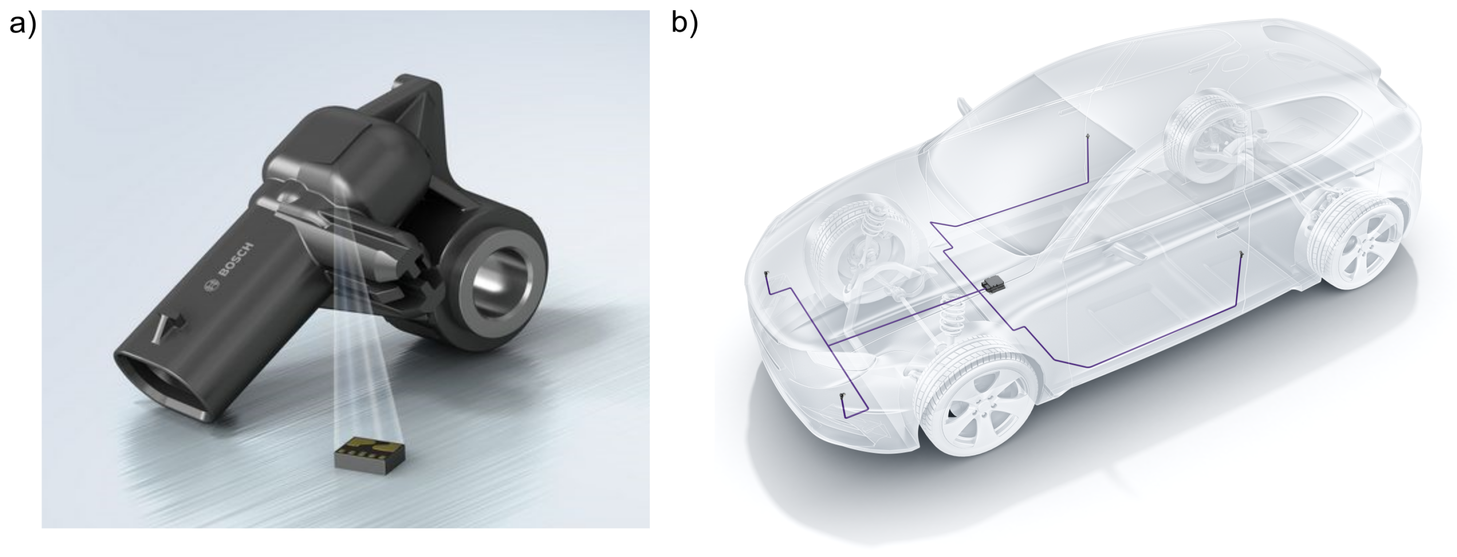
:1. Introduction
2. Current State of Research
3. Motive and Aim
- The transfer of established sensors is possible for future FRP vehicle structures. There is no need to develop and validate new sensors or sensor joints.
- The number of independently mounted sensors, as well as the wiring harness system, is reduced, additionally saving weight and construction space of a vehicle.
- Several sensing applications are well combinable; mounted sensors, connectors and the cable harness limit that. Automotive sensor concepts can be more complex.
- The integration opens up the potential of additional sensor applications for established sensors. This extends the application range of these sensors.
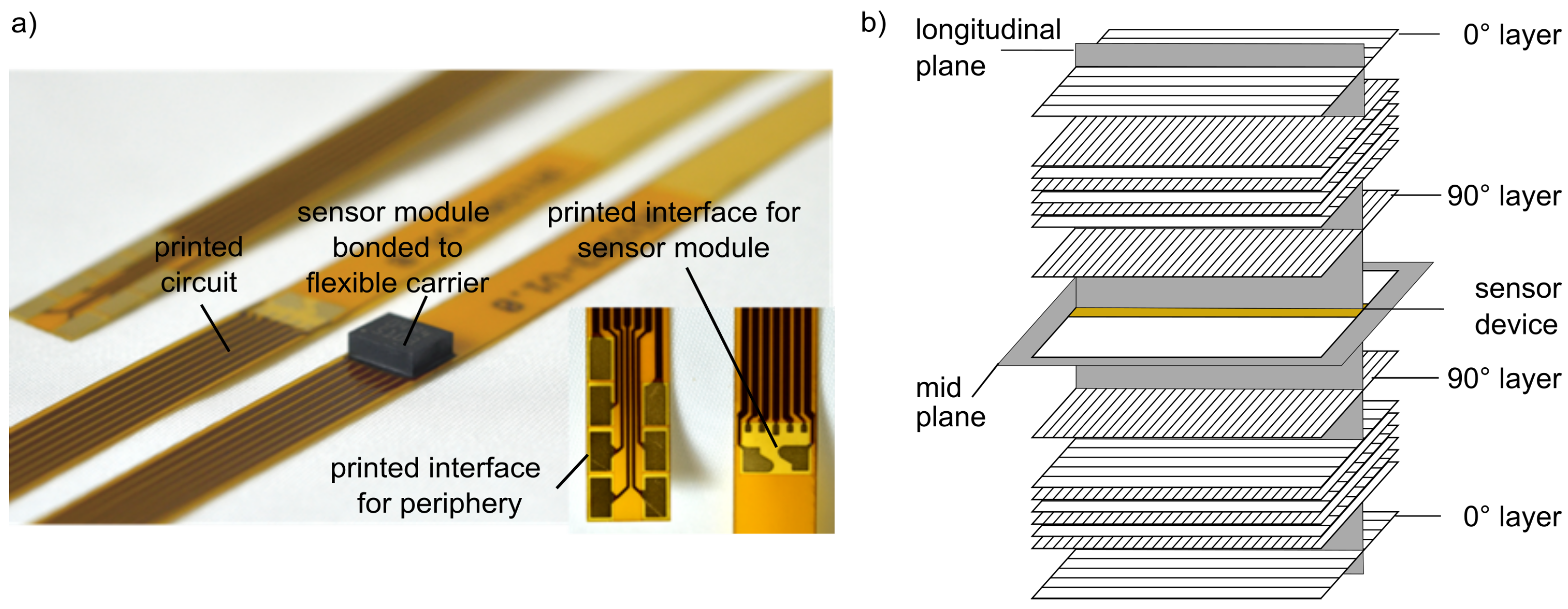
4. Technological Implementation
5. Structural Component Quality and Mechanics
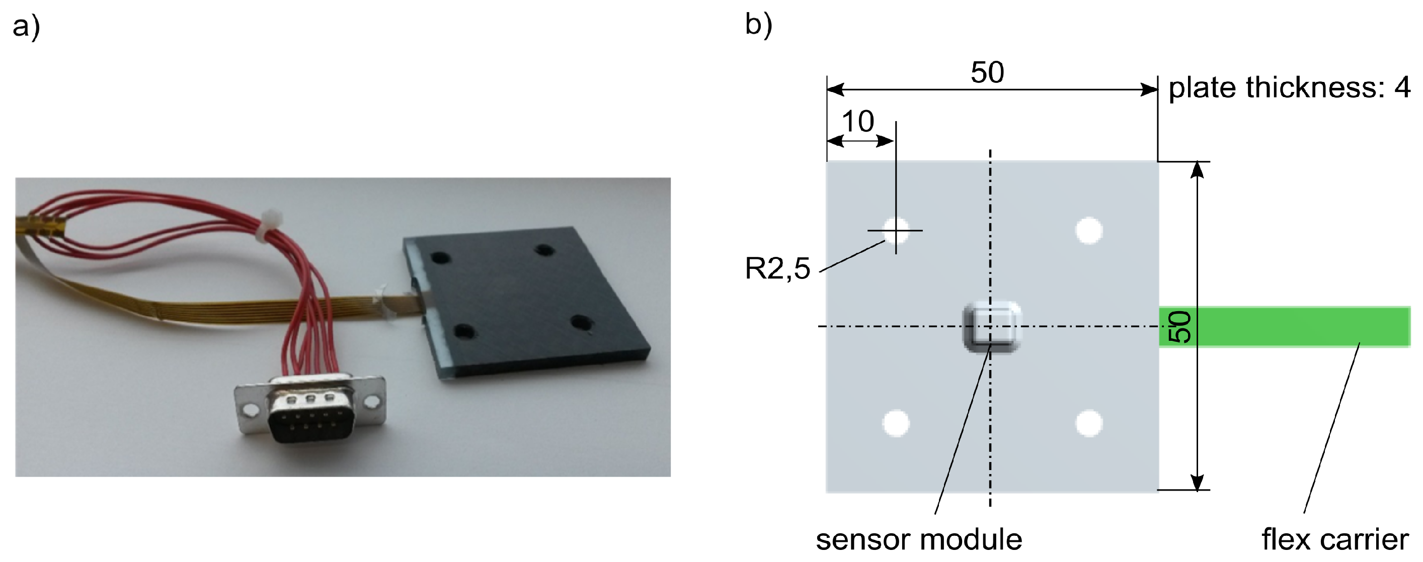
5.1. Methods and Materials
5.2. Results
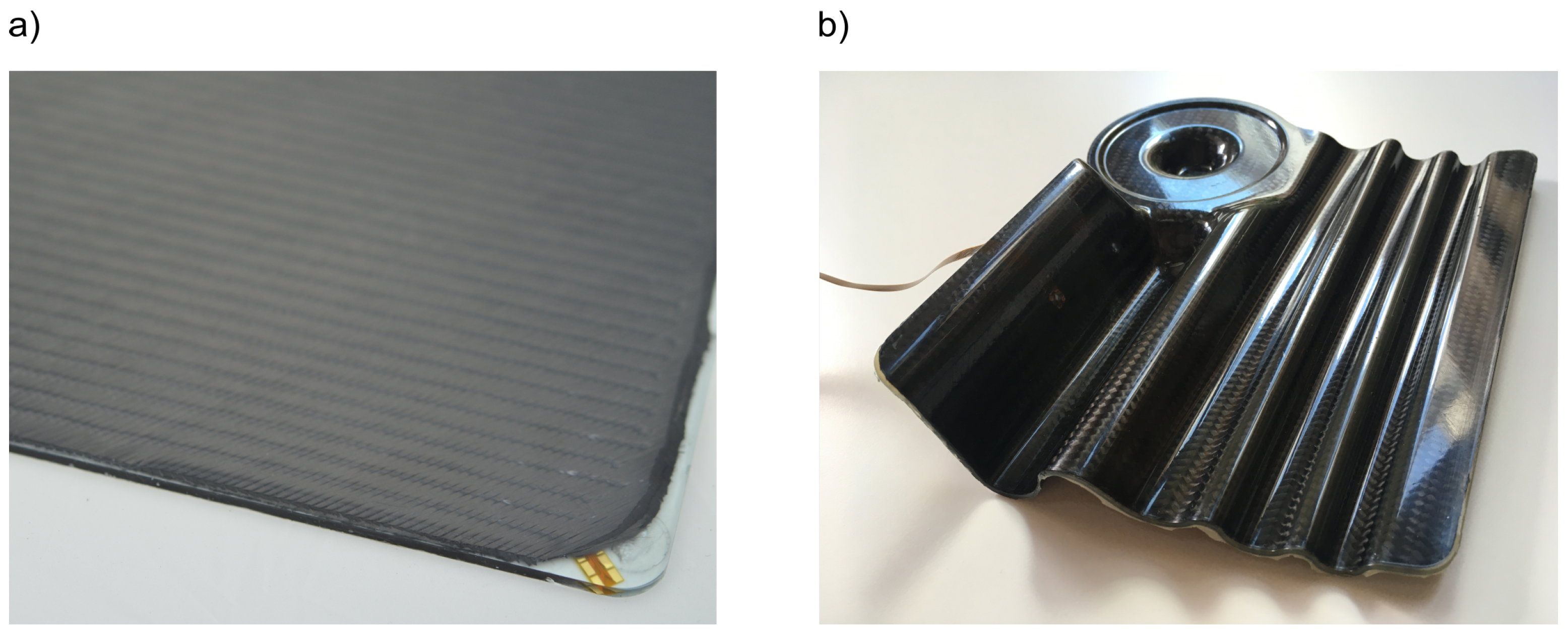
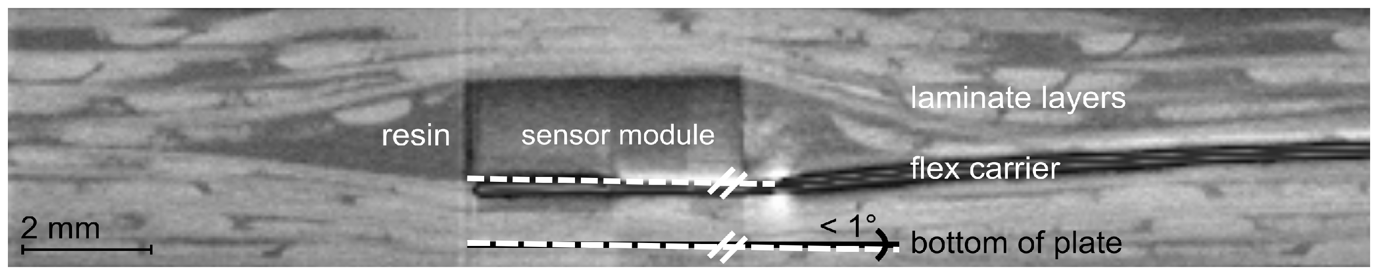
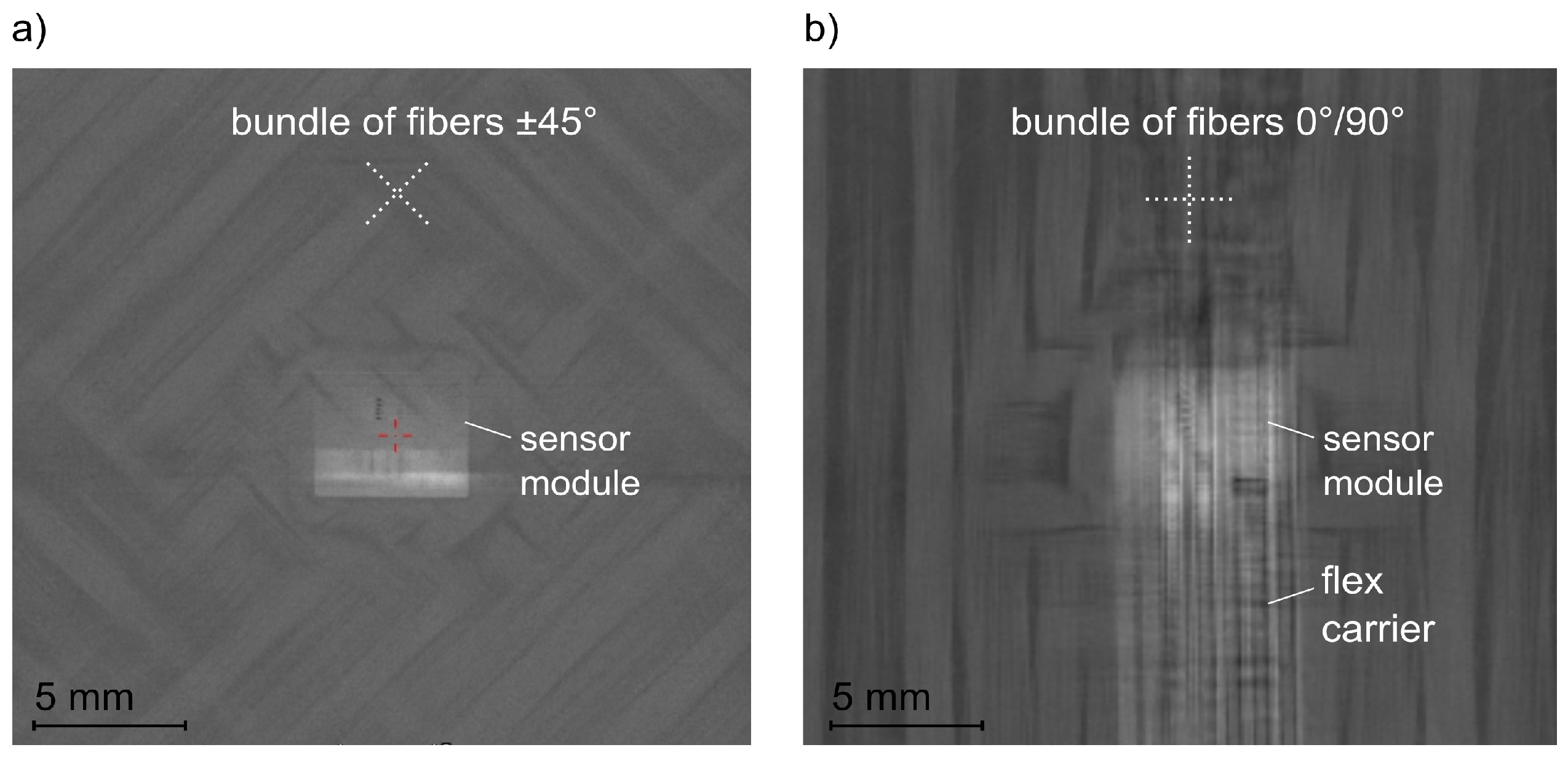
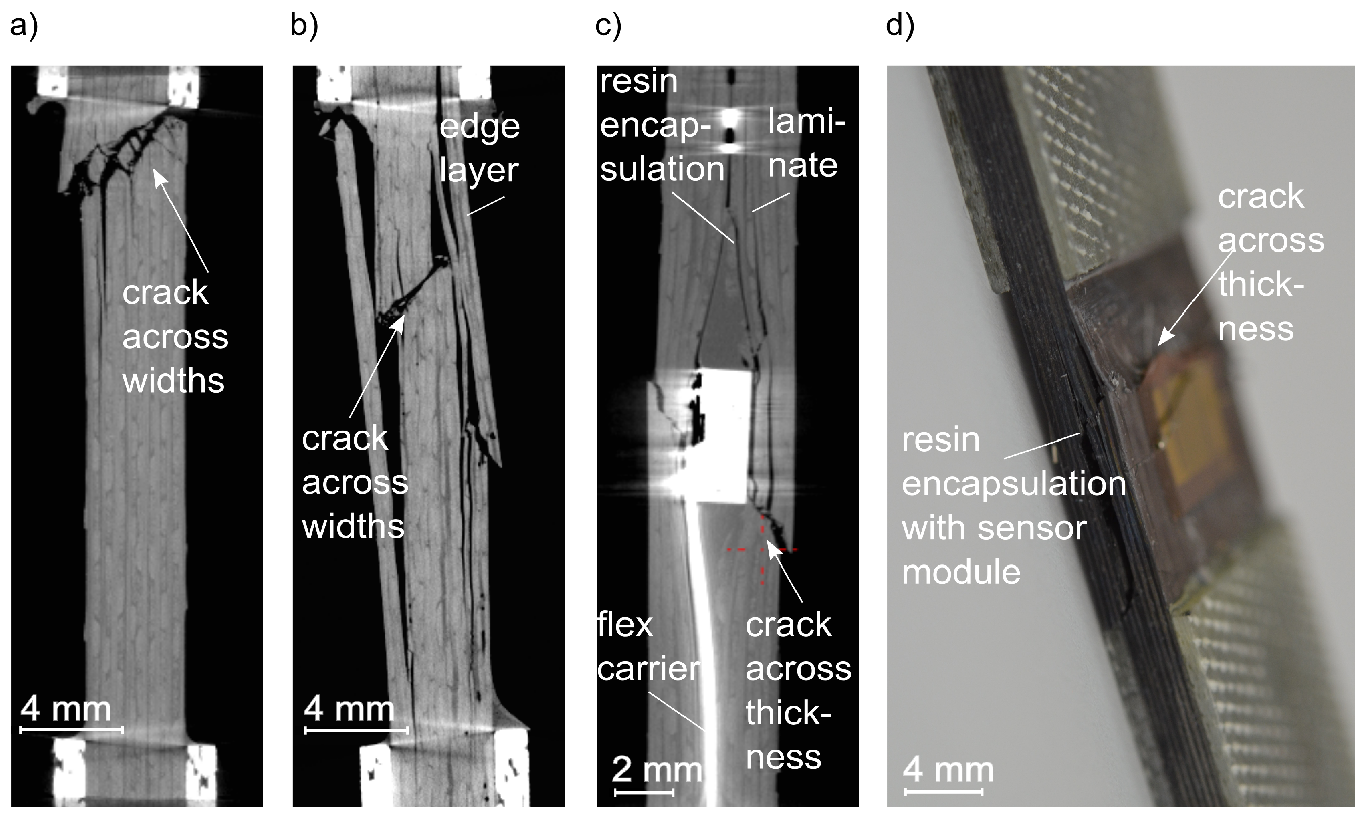
5.2.1. Integration Quality
5.2.2. Mechanical Properties
5.3. Discussion
6. Crash Sensing
6.1. Methods and Materials
6.2. Results
6.3. Discussion
7. Conclusions
Author Contributions
Funding
Acknowledgments
Conflicts of Interest
Abbreviations
| CFRP | Carbon fibre-reinforced polymers |
| CNT | Carbon nano tubes |
| CT | Computer tomography |
| FRP | Fibre-reinforced polymers |
| IoT | Internet of Things |
| LCM | Liquid composite moulding |
| MEMS | Micro electro mechanical system |
| RTM | Resin transfer moulding |
References
- Monner, H.P.; Rose, M. Adaptive, Tolerant and Efficient Composite Structures, Research Topics in Aerospace. In Autonomous Composite Structures; Wiedemann, M., Sinapius, M., Eds.; Springer: Berlin/Heidelberg, Germany, 2013; pp. 375–380. [Google Scholar]
- Thursby, G.; Sorazu, B.; Dong, F.; Betz, D.C.; Culshaw, B. Damage Detection in Structural Materials using a Polarimetric Fibre Optic Sensor. Proc. SPIE 2003, 5050, 287–295. [Google Scholar]
- Schubert, K.J.; Herrmann, A.S. On attenuation and measurement of lamb waves in viscoelastic composites. Compos. Struct. 2011, 94, 177–185. [Google Scholar] [CrossRef]
- Winkler, A.; Modler, N.; Dannemann, M.; Starke, E.; Holeczek, K. Aktive faserverstärkte Thermoplastverbunde mit materialhomogenen integrierten Piezokeramikmodulen, ein Ausblick. In Smarte Strukturen und Systeme, Proceedings of the Tagungsband des 4SMARTS-Symposiums Darmstadt, Germany, 6–7 April 2016; Wiedemann, M., Ed.; DeGruyter: Berlin, Germany, 2016; pp. 172–181. [Google Scholar]
- Boehme, B.; Roellig, M.; Lautenschlaeger, G.; Franke, M.; Schulz, J.; Wolter, K.-J. Strukturintegrierte Ultraschallsensorik und -elektronik in CFK-Baugruppen für die Zustandsüberwachung. PLUS 2013, 10, 848–855. [Google Scholar]
- Sodano, H.A.; Park, G.; Inman, D.J. An Investigation into the performance of macro-fiber ccomposite for sensing and structural vibration applications. Mech. Syst. Signal Process. 2004, 18, 683–697. [Google Scholar] [CrossRef]
- Herszberg, I.; Bannister, M.K.; Li, H.C.H.; Thomson, R.S.; White, C. Structural Health Monitoring For Advanced Composite Structures. In Proceedings of the Sixteenth International Conference on Composite Materials (ICCM 16), Kyoto, Japan, 8–13 July 2007; ICCM-16 Local Organizing Committee: Kyoto, Japan, 2007. [Google Scholar]
- Ghoshal, A.; Ayers, J.; Gurvich, M.; Urban, M.; Bordick, N. Experimental Investigation in Embedded Sensing for Structural Health Monitoring of Composite Components in Aerospace Vehicles. In Proceedings of the ASME 2012 Conference on “Smart Materials, Adaptive Structures and Intelligent Systems”, Stone Mountain, GA, USA, 19–21 September 2012; Volume 1, pp. 845–854. [Google Scholar]
- Murukeshan, V.M.; Chan, P.Y.; Ong, L.S.; Seah, L.K. Cure Monitoring of smart composites using Fiber Bragg Grating based embedded sensors. Sens. Actuators A Phys. 2000, 79, 153–161. [Google Scholar] [CrossRef]
- Wevers, M.; Rippert, L.; Van Huffel, S. Optical fibres for in-situ monitoring the damage development in composites. In Proceedings of the 15th World Conference on Nondestructive Testing, Roma, Italy, 15–21 October 2000; pp. 41–50. [Google Scholar]
- Huang, Y.; Nemat-Nasser, S. Structural Integrity of Composite Laminates with Embedded Microsensors. In Sensor Systems and Networks: Phenomena, Technology and Applications for NDE and Health Monitoring; Peters, K.J., Ed.; SPIE: Bellingham, WA, USA, 2007; Volume 6530. [Google Scholar]
- Schueller, M.; Lipowski, M.; Grossmann, T.; Troltzsch, J.; Geßner, T.; Kroll, L. Integration von Mikro- und Nanosystemen in Hybride Strukturen. In Proceedings of the Smarte Strukturen und Systeme, Tagungsband des 4SMARTS-Symposiums, Darmstadt, Germany, 6–7 April 2016; Wiedemann, M., Ed.; DeGruyter: Berlin, Germany, 2016; pp. 161–171. [Google Scholar]
- Torres, A.M.; Crouzeix, L.; Collombet, F.; Douchin, B.; Grunevald, Y.-H. Mechanical Charaterization of an Alternative Technique to Embed Sensors in Composite Sructures: The Monitoring Patch. Appl. Compos. Mater. 2010, 19, 379–391. [Google Scholar] [CrossRef]
- Nestler, D.; Karapepas, C. Beitrag für Carbon Composite e.V.. Sensorintegration in Thermoplastbasierte Hybride Laminate. Artefaktfreie in-Line Integration von Intelligenten SHM-Komponenten; Bundesexzellenzcluster MERGE TU Chemnitz: Chemnitz, Germany, 2016. [Google Scholar]
- Ebert, F.; Seider, T.; Illing-Günther, H.; Nendel, K.; Martin, J.; Otto, T.; Gessner, T.; Nestler, D.; Wagner, G. Integration of humidity sensors into fibre-reinforced thermoplastic composites. Procedia Technol. 2016, 26, 207–213. [Google Scholar] [CrossRef]
- Ullmann, F.; Decker, R.; Graf, A.; Krausel, V.; Heinrich, M.; Hardt, W.; Kroll, L.; Landgrebe, D. Continuous Manufacturing of Piezoceramic Hybrid Laminates for Functionalised Formed Structural Components. Technol. Lightweight Struct. 2017, 1. Available online: https://www.lightweight-structures.de/issue/view/11 (accessed on 27 June 2019).
- Kloepfer, J. Entwicklung Eines Load-Monitoring-Systems für Sportgeräte. Fraunhofer-Allianz Adaptronik. 2013. Available online: https://www.adaptronik.fraunhofer.de/de/appl1/sport/monit/paddel.html (accessed on 5 May 2019).
- Maron, B.; Weck, D.; Filippatos, A.; Hohne, R.; Krahl, M.; Kostka, P.; Langkamp, A.; Modler, N. Die vernetzte Karosserie: Funktionsintegrativer Leichtbau mit Hybridgarn-Textil-Thermoplast-Vebunden. Kunststoffe 2016, 3, 46–49. [Google Scholar]
- Christof, H.; Klein, L.; Frank, E.; Giebel, E.; Kueppers, S.; Mueller, L.; Bahroun, K.; Buchmeiser, M.; Gresser, G.T.; Middendorf, P. Integrated Sensors for Structural Health and Crash Monitoring in Carbon Fiber Reinforced Polymers. In MERGE, Proceedings of the 2nd International MERGE Technologies Conference, IMTC 2015 Lightweight Structures, Universität Chemnitz, Germany, 1–2 October 2015; Kroll, L., Ed.; Verlag Wissenschaftliche Scripten: Auerbach, Germany, 2015; pp. 211–2018. [Google Scholar]
- Horoschenkoff, A. Carbonfaser: Sensorelement für funktionelle Faserverbundwerkstoffe. LWD 2014, 2, 28–33. [Google Scholar] [CrossRef]
- Anike, J.C.; Belay, K.; Abot, J.L. Piezoresistive response of carbon nanotube yarns under tension: Parametric effects and phenomenology. New Carbon Mater. 2018, 33, 140–154. [Google Scholar] [CrossRef]
- Abot, J.L.; Góngora-Rubio, M.R.; Anike, J.C.; Kiyono, C.Y.; Mello, L.A.M.; Cardoso, V.F.; Rosa, R.L.S.; Kuebler, D.A.; Brodeur, G.E.; Alotaibi, A.H.; et al. Foil Strain Gauges Using Piezoresistive Carbon Nanotube Yarn: Fabrication and Calibration. Sensors 2018, 18, 464. [Google Scholar] [CrossRef] [Green Version]
- Lu, S.; Chen, D.; Wang, X.; Xiong, X.; Ma, K.; Zhang, L.; Meng, Q. Monitoring the manufacturing process of glass fiber reinforced composites with carbon nanotube buckypaper sensors. Polym. Test. 2016, 52, 79–84. [Google Scholar] [CrossRef]
- Chang, F.-K. From Smart Sensing to Multifunctional Materials: Are we ready for the challenges? In Proceedings of the 19th International Conference on Composite Materials (ICCM 19), Montreal, QC, Canada, 28 July–2 August 2013. [Google Scholar]
- Inaudi, D.; Glisic, B. Integration of distributed strain and temperature sensors in composite coiled tubing. In Proceedings of the SPIE Smart Structures and Materials + Nondestructive Evaluation and Health Monitoring, San Diego, CA, USA, 26 February–2 March 2006; SPE Library: Bethel, NY, USA, 2006. [Google Scholar]
- Konstantopoulos, S.; Fauster, E.; Schledjewski, R. Monitoring the production of FRP composites: A review of in-line sensing methods. eXPRESS Polym. Lett. 2014, 8, 823–840. [Google Scholar] [CrossRef]
- Moghaddam, M.K.; Breede, A.; Brauner, C.; Lang, W. Embedding Piezoresistive Pressure Sensors to Obtain Online Pressure Profiles Inside Fiber Composite Laminates. Sensors 2015, 15, 7499–7511. [Google Scholar] [CrossRef] [Green Version]
- Tuncol, G.; Danisman, M.; Kaynar, A.; Sozer, E.M. Constraints on monitoring resin flow in the resin transfer molding (RTM) process by using thermocouple sensors. Compos. Part A Appl. Sci. Manuf. 2007, 38, 1363–1386. [Google Scholar] [CrossRef]
- Moghaddam, M.K.; Breede, A.; Chaloupka, A.; Boedecker, A.; Habben, C.; Meyer, E.-M.; Brauner, C.; Lang, W. Design, fabrication and embedding of microscale interdigital sensors for real-time cure monitoring during composite manufacturing. Sens. Actuators A Phys. 2015, 243, 123–133. [Google Scholar] [CrossRef]
- Schmachtenberg, E.; Schulte zur Heide, J.; Töpker, J. Application of ultrasonics for the process control of Resin Transfer Moulding (RTM). Polym. Test. 2004, 24, 330–338. [Google Scholar] [CrossRef]
- Schmidt, J.; Opitz, M.; Liebers, N. Evaluation and calibration of tool independent cure monitoring systems for epoxy resins. In Proceedings of the 10th International Conference on Composite Science and Technology (ICCST/10), Lisbon, Portugal, 2–4 September 2015. [Google Scholar]
- Ehrenstein, G.W. Handbuch Kunststoff-Verbindungstechnik; Carl Hanser: München, Germany, 2004. [Google Scholar]
- Schürmann, H. Konstruieren mit Faser-Kunststoff-Verbunden; Springer: Berlin, Germany, 2007. [Google Scholar]
- Beyer, U. Herstellung eines Metall-Kunststoff-Verbundes mit der Flach-Clinch-Technologie. In Flach-Clinch-Technologie; Meisenbach: Bamberg, Germany, 2011; p. 10. [Google Scholar]
- Anon. T–IGEL Technologie Composite-Technology. In Composite Braiding, Composite-Metall-Anbindung, Composite-Technology; Teufelsberger GesmbH: Wels, Germany, 2010; p. 9. [Google Scholar]
- Gradinger, R.; Ucsnik, S.; Schumann, T. FEM-Basierte Untersuchungen Einer Innovativen Metall-FVK Fügetechnik. Available online: https://docplayer.org/25708706-Fem-basierte-untersuchungen-einer-innovativen-metall-fvk-fuegetechnik.html (accessed on 15 October 2021).
- Lahr, R. Partielles Thermoformen Endlosfaserverstärkter Thermoplaste. Ph.D. Thesis, Technische Universität Kaiserslautern, Institut für Verbundwerkstoffe, Kaiserslautern, Germany, 2007. [Google Scholar]
- Seidlitz, H.; Kroll, L.; Ulke-Winter, L. Kraftflussgerechte Punktverbindungen. Hochbelastete Leichtbaustrukturen. Kunststoffe 2011, 3, 50–53. [Google Scholar]
- Schievenbusch, F. Beitrag zu Hochbelasteten Krafteinleitungselementen für Faserverbundbauteile. Ph.D. Thesis, Technische Universität Chemnitz, Fakultät für Maschinenbau und Verfahrenstechnik, Chemnitz, Germany, 2003. [Google Scholar]
- Hufenbach, W.; Kupfer, R.; Pohl, M. Montagesysteme für Leichtbaustrukturen in der Großserie. Konstruktion 2013, 1, 6–8. [Google Scholar]
- Klein, L. Seriensensoren für die Faserverbund-Karosserie. Funktionalisierter Leichtbau und Schadensmonitoring. In Automobiltechnische Zeitschrift 11/2019, 121. Jahrgang; Springer: Heidelberg, Germany, 2019; pp. 48–53. [Google Scholar]
- Klein, L. Serial Sensors for the Fiber Composite Body Functionalized Lightweight Design and Damage Monitoring. In ATZ Worldwide 11/2019; Springer: Heidelberg, Germany, 2019; pp. 44–47. [Google Scholar]
- Klein, L. Sensor Systems for FRP Lightweight Structures. Automotive Features based on Serial Sensor Products. Sensors 2019, 14, 3088. [Google Scholar] [CrossRef] [Green Version]
- Klein, L. Methods of Manufacturing and Testing of Fiber Composite Parts and Fiber Composite Component. CN Patent 112213470 A, 9 July 2020. [Google Scholar]
- Klein, L. Faserverbundbauteil, Verwendung des Faserverbundbauteils, Diverse Verfahren. DE Patent 10 2018 221 012 A1, 5 December 2018. Available online: https://patentscope.wipo.int (accessed on 15 October 2021).
- Klein, L. Manufacturing Methods for Fiber Composite Parts, Fiber Composite Parts, Inspection Methods for Fiber Composite Parts, Computer Programs, Machine-Readable Storage Media and Devices. JP Patent 2021014117 A2, 9 July 2020. [Google Scholar]
- Klein, L. Method for Testing a Fiber-Reinforced Composite Component, Device, Computer Program, and Machine-Readable Storage Medium. U.S. Patent US 2020/0182740 AA, 5 November 2019. International Patent WO2021/004851 A1, 1 July 2020. Available online: https://patentscope.wipo.int (accessed on 15 October 2021).
- Klein, L. Method for Testing a Composite Fiber Component, Composite Fiber Component, Testing Method for a Composite Fiber Component, Computer Program, Machine-Readable Storage Medium, and Apparatus. WO Patent 2020/1 15056 A1, 3 December 2019. Available online: https://patentscope.wipo.int (accessed on 15 October 2021).
- Klein, L. Method and Apparatus for Testing Fiber Composite Parts. CN Patent 111272646 A, 3 December 2019. [Google Scholar]
- Klein, L. Method for Testing a Fiber Composite Component, Device, Computer Program and Machine-Readable Storage Medium. South Korea Patent KR 20190159057, 3 December 2019. Japan Patent JP 20190219489, 4 December 2019. [Google Scholar]
- Klein, L. Herstellungsverfahren für Ein Faserverbundbauteil, Faserverbundbauteil, Prüfverfahren für Ein Faserverbundbauteil, Computerprogramm, Maschinenlesbares Speichermedium und Vorrichtung. DE Patent 10 2019 210 171 A1, 10 July 2019. [Google Scholar]
- Klein, L. Verfahren zur Prüfung Eines Faserverbundbauteils, Vorrichtung, Computerprogramm und Maschinenlesbares Speichermedium. DE Patent 10 2018 221 016 A1, 5 December 2018. [Google Scholar]
- Klein, L. Production Method for a Fiber Composite Component, Fiber Composite Component, Testing Method for a Fiber Composite Component, Computer Program, Machine-Readable Storage Medium, and Device. U.S. Patent 2021/0010940 A1, 9 July 2020. [Google Scholar]
- Huening, F. (Ed.) Sensoren und Sensorschnittstellen; DeGruyter: Berlin, Germany, 2016. [Google Scholar]
- Reif, K. (Ed.) Automobilelektronik. Eine Einführung für Ingenieure; Vieweg und Teubner: Wiesbaden, Germany, 2007. [Google Scholar]
- Klein, L.; Kugler, A.; Schönfeld, D. Inventors. Robert Bosch GmbH, Applicant. Method for Arranging a Number of Micromechanical Acceleration Sensors on or in a Plastic Component, and Corresponding Plastic Component. China Patent CN 109844543 A, 29 September 2017. International Patent WO2018 069066 A1, 29 September 2017. [Google Scholar]
- Klein, L.; Kugler, A.; Schönfeld, D. Inventors. Robert Bosch GmbH, Applicant. Verfahren zum Anordnen Einer Anzahl von Mikromechanischen Beschleunigungssensoren auf Oder in Ein Kunststoffbauteil und Entsprechendes Kunststoffbauteil. DE Patent 10 2016 220 068 A1, 14 October 2016. [Google Scholar]
- Graebener, M. Prozessoptimierung zur Integration von Sensorik in Faserverbundkunststoffe Mittels VARI. Bachelor’s Thesis, Hochschule Esslingen, Robert Bosch GmbH, Esslingen, Stuttgart, Germany, 2015. [Google Scholar]
- Klein, L.; Middendorf, P. Novel Integration Concepts for Automotive Sensors in Composite Structures. In ANTEC Orlando 2015; SPE Library: Bethel, NY, USA, 2015. [Google Scholar]
- Klein, L.; Middendorf, P. Functionalized Lightweight Parts: Application of LCM for the Integration of Automotive Sensors in CFRP Structures. In PPS Graz 2015; AIP Publishing LCC: Melville, NY, USA, 2015. [Google Scholar]
- Klein, L.; Middendorf, P. Designte Sensorfunktionalität im Automobilleichtbau mit Faserverbundkunststoff (eine Systembetrachtung). In Proceedings of the Tagungsband des 4SMARTS Symposiums vom Smarte Strukturen und Systeme, Darmstadt, Germany, 6–7 April 2016; Wiedemann, M., Ed.; DeGruyter: Berlin, Germany, 2016; pp. 194–210. [Google Scholar]
- Klein, L. Produktintegration Etablierter Sensoren in Faserverbundkunststoffe. Ph.D. Thesis, Technische Universität Bergakademie Freiberg, Institut für Elektronik- und Sensormaterialien, Freiberg, Germany, 2021. [Google Scholar]
- Klein, L. Fiber Composite Component, Use of the Fiber Composite Component, and Diverse Method. WO Patent 2020/115057 A1, 3 December 2019. [Google Scholar]
- Klein, L. Method for Producing a Fiber Composite Component, and Fiber Composite Component. WO Patent 2020/1 15055 A1, 3 December 2019. [Google Scholar]
- Klein, L. Verfahren zur Herstellung Eines Faserverbundbauteils und Faserverbundbauteil. DE Patent 10 2018 221 009 A1, 5 December 2018. Available online: https://www.freepatentsonline.net/DE102018221009A1.html (accessed on 18 October 2021).
- Kallmeyer, C. Technologiestudie zum Bonden von Ultradünnen ICs Auf Folien, Integration in Mehrlagenstapel und Packages. Technology Study; Robert Bosch: Renningen, Germany, 2015. [Google Scholar]
- Hedderich, J.; Sachs, L. Angewandte Statistik. Methodensammlung mit R, 15th ed.; Springer Spektrum: Heidelberg, Germany, 2016. [Google Scholar]
- Ehrenstein, G.W. Faserverbund-Kunststoffe: Werkstoffe, Verarbeitung, Eigenschaften, 2nd ed.; Carl Hanser: München, Germany, 2006. [Google Scholar]
- Nössner, S. Einfluss der Fahrzeugstruktur auf Beschleunigungsbasierte Crashsignale. Beschleunigungssignale im Fahrzeugcrash. Ph.D. Thesis, Technische Universität Bergakademie Freiberg, Institut für Maschinenelemente, Konstruktion und Fertigung, Freiberg, Germany, 2015. [Google Scholar]
- Kröeger, M. Methodische Auslegung und Erprobung von Fahrzeug-Crashstrukturen. Ph.D. Thesis, Universität Hannover, Fachbereich Maschinenbau, Hannover, Germany, 2002. [Google Scholar]
- Abramowicz, W.; Jones, N. Dynamic progressive buckling of circular and square tubes. Int. J. Impact Eng. 1986, 3, 263–281. [Google Scholar] [CrossRef]
- Al Galib, D.; Limam, A. Experimental and numerical investigation of static and dynamic axial crushing of circular aluminum tubes. Thin-Walled Struct. 2004, 42, 1103–1137. [Google Scholar] [CrossRef]
- Klein, L.; Joseph, Y. Funktionsintegration mit Crashsensorik in FVK-Strukturen. In 10. Freiberger Crashworkshop. Passive Sicherheit: Auslegung, Simulation, Werkstoffe. IMKF, TU Bergakademie Freiberg; Technische Universität Bergakademie Freiberg: Freiberg, Germany, 2019. [Google Scholar]
- Klein, L.; Middendorf, P. Automobilsensoren: Eigenschaften einer Sensorintegration mittels Liquid Composite Molding. In Technomer 2015 TU Chemnitz; TU Chemnitz: Chemnitz, Germany, 2015. [Google Scholar]
- Nössner, S.; Kolatschek, J.; D’Addetta, G.A.; Kröger, M. Methodology to predict and validate acceleration based crash signals in the early phase of the automotive product design cycle. In Proceedings of the Airbag 2014, Karlsruhe, Germany, 25 February 2014. [Google Scholar]
- Nössner, S.; Kolatschek, J.; D’Addetta, G.A.; Kröger, M. Crashsignale und Leichtbaukonzepte. Methodik zur Bewertung neuer Materialien im frühen Stadium des Fahrzeug-Produktentstehungsprozesses. In Proceedings of the SIMVEC 2014, Baden-Baden, Germany, 18–19 November 2014. [Google Scholar]
- Czichos, H. Mechatronik. Grundlagen und Anwendungen Technischer Systeme, 4th ed.; Springer Vieweg: Berlin, Germany, 2019. [Google Scholar]
- Velten, T Mikromechanisch Gefertigter 3D-Beschleunigungssensor für Die Hand-Gebärdenerfassung. Ph.D. Thesis, Technische Universität Berlin, Berlin, Germany, 2000.
- Beste, D. Klein, kleiner, am kleinsten. Springerprofessional Mikrosystemtechnik. 2019. Available online: https://www.springerprofessional.de/mikrosystemtechnik/materialentwicklung/klein–kleiner-am-kleinsten/17137768 (accessed on 28 May 2021).
- Güth, F.; Arki, P.; Löher, T.; Ostmann, A.; Joseph, Y. Electrochemical sensors based on printed circuit board technologies. Procedia Eng. 2016, 168, 452–455. [Google Scholar] [CrossRef]
- Güth, F.; Arkia, P.; Joseph, Y. Chemische Sensoren für die Industrie 4.0. In ACAMONTA: Zeitschrift für Freunde und Förderer der Technischen Universität Bergakademie Freiberg; Freunde und Förderer der Technischen Universität Bergakademie Freiberg e.V.: Freiberg, Germany, 2016; Volume 23. [Google Scholar]
- Hartwig, M.; Zichner, R.; Joseph, Y. Inkjet–Printed Wireless Chemiresistive Sensors. A Review. Chemosensors 2018, 6, 66. [Google Scholar] [CrossRef] [Green Version]
- Güth, F.; Grehl, S.; Lösch, R.; Varga, S.; Rezaei, N.; Günther, F.; Mischo, H.; Benndorf, J.; Joseph, Y.; Rehkopf, A.; et al. Sutonomous Robots and the Internet of Things in Underground Mining. Project: ARIDuA. In Proceedings of the Smart Systems Integration 2018, Dresden, Germany, 11–12 April 2018. [Google Scholar]


| Specific Value | Reference | Self-Sensing | Regular | ||
|---|---|---|---|---|---|
| CFRP structure [0/90]S | |||||
| Tensile test (DIN EN ISO 527-4) | |||||
| Fibre content (%vol.) | 60 | 36 | 35 | ||
| Tensile modulus (GPa) | 69.2 (2.1) | 43 (1.2) | 41.4 (1.3) | ||
| Tensile strength (MPa) | 1064 (98.3) | 699 (19.0) | * | 607 (48.5) | |
| Elongation at break (%) | 1.47 (0.05) | 1.54 (0.03) | * | 1.3 (0.05) | |
| Compression test (DIN EN ISO 14126) | |||||
| Fibre content (%vol.) | 62 | 35 | 35 | ||
| Compressive modulus (GPa) | 69.3 (1.0) | ** | 41.4 (0.2) | 40.1 (1.5) | |
| Compressive strength (MPa) | 572 (22.2) | ** | 283 (37.2) | * | 395 (12.3) |
| Compression (%) | 0.92 (0.04) | 0.71 (0.11) | * | 1.15 (0.06) | |
| Bending test (DIN EN ISO 14125) | |||||
| Fibre content (%vol.) | 61 | 35 | 35 | ||
| Bending modulus (GPa) | 75.3 (3.1) | 46.6 (2.5) | 44.5 (2.2) | ||
| Bending strength (MPa) | 918 (68.2) | 683 (28) | 663 (40.9) | ||
| Bending strain (%) | 1.33 (0.1) | 1.74 (0.1) | 1.76 (0.06) | ||
| CFRP structures [±45]S | |||||
| Tensile test (DIN EN ISO 527-4) | |||||
| Fibre content (%vol.) | 61 | 35 | 34 | ||
| Tensile modulus (GPa) | 4.6 (0.04) | 2.9 (0.03) | 2.7 (0.2) | ||
| Tensile strength (MPa) | 62.8 (0.3) | 51.4 (0.8) | 50.2 (1.3) | ||
| Compression test (DIN EN ISO 14126) | |||||
| Fibre content (%vol.) | 60 | 33 | 33 | ||
| Compressive modulus (GPa) | 15.2 (1.0) | 10.6 (0.8) | * | 8.3 (0.5) | |
| Compressive strength (MPa) | 160.1 (9.4) | ** | 120 (1.2) | 122 (0.6) | |
| Compression (%) | 10.27 (0.51) | 10.87 (0.34) | * | 12.72 (0.02) | |
Publisher’s Note: MDPI stays neutral with regard to jurisdictional claims in published maps and institutional affiliations. |
© 2021 by the authors. Licensee MDPI, Basel, Switzerland. This article is an open access article distributed under the terms and conditions of the Creative Commons Attribution (CC BY) license (https://creativecommons.org/licenses/by/4.0/).
Share and Cite
Klein, L.; Joseph, Y.; Kröger, M. Product Integration of Established Crash Sensors for Safety Applications in Lightweight Vehicles. Sensors 2021, 21, 6994. https://doi.org/10.3390/s21216994
Klein L, Joseph Y, Kröger M. Product Integration of Established Crash Sensors for Safety Applications in Lightweight Vehicles. Sensors. 2021; 21(21):6994. https://doi.org/10.3390/s21216994
Chicago/Turabian StyleKlein, Linda, Yvonne Joseph, and Matthias Kröger. 2021. "Product Integration of Established Crash Sensors for Safety Applications in Lightweight Vehicles" Sensors 21, no. 21: 6994. https://doi.org/10.3390/s21216994