Hysteresis Modelling and Feedforward Control of Piezoelectric Actuator Based on Simplified Interval Type-2 Fuzzy System


1
Robotics for Extreme Environments Lab, Department of Electrical and Electronic Engineering, University of Manchester, Manchester M13 9PL, UK
2
Changchun Institute of Optics, Fine Mechanics and Physics, Chinese Academy of Sciences, Changchun 130033, China
*
Authors to whom correspondence should be addressed.
Sensors 2020, 20(9), 2587; https://doi.org/10.3390/s20092587
Submission received: 24 March 2020
/
Revised: 22 April 2020
/
Accepted: 29 April 2020
/
Published: 2 May 2020
(This article belongs to the Special Issue Piezoelectric Transducers)
Abstract
:The piezoelectric actuator is indispensable for driving the micro-manipulator. In this paper, a simplified interval type-2 (IT2) fuzzy system is proposed for hysteresis modelling and feedforward control of a piezoelectric actuator. The partial derivative of the output of IT2 fuzzy system with respect to the modelling parameters can be analytically computed with the antecedent part of IT2 fuzzy rule specifically designed. In the experiments, gradient based optimization was used to identify the IT2 fuzzy hysteresis model. Results showed that the maximum error of model identification is 0.42% with only 3 developed IT2 fuzzy rules. Moreover, the model validation was conducted to demonstrate the generalization performance of the identified model. Based on the analytic inverse of the developed model, feedforward control experiment for tracking sinusoidal trajectory of 20 Hz was carried out. As a result, the hysteresis effect of the piezoelectric actuator was reduced with the maximum tracking error being 4.6%. Experimental results indicated an improved performance of the proposed IT2 fuzzy system for hysteresis modelling and feedforward control of the piezoelectric actuator.
1. Introduction
Smart material based actuators are new types of actuators different from the traditional electromagnetic actuators. Among these smart actuators, the piezoelectric actuator is widely used in the field of micro-/nano- positioning and manipulation [1,2,3,4,5,6], biomedical robotics and extreme environments [7,8,9,10] and optics [11,12,13] due to its extraordinary characteristics such as nanometer-scale displacement resolution, nonexistent friction and fast response.
However, the nonlinear hysteresis of the piezoelectric actuator has an influence on the positioning or manipulating accuracy of these applications. Under the hysteresis effect, the displacement of the piezoelectric actuator is a function of not only the current input voltage but also the previous displacement or input voltage.
Various modelling methods and control strategies have been proposed to tackle the hysteresis and its effect. The Prandtl-Ishlinskii model [14,15,16,17] was widely investigated for describing the rate-independent and rate-dependent, symmetric and asymmetric hysteresis. Preisach model [18,19], Duhem model [20], fuzzy system [21,22] and neural networks [23] were also presented to characterizing hysteresis. Regarding control strategies, feedback control algorithms incorporating feedforward control were mainly developed, such as finite-time learning control [24], iterative control [25,26], internal model-based feedback control [17] and fuzzy control [27].
Extensive research works into interval type-2 (IT2) fuzzy system were carried out during the last decades [28]. In fact, IT2 fuzzy system has more freedom of flexibility to describe the complex phenomenon than traditional type-1 fuzzy system, that makes it capable of modelling the nonlinear system more precisely. It has been applied in nonlinear modelling and automatic control in various studies [29,30,31,32,33,34].
In this paper, an IT2 fuzzy system with an analytic inverse was designed, and applied to hysteresis modelling and feedforward control of the stacked piezoelectric actuator with practical experiments. The remaining organization of this paper is as follows: in Section 2 the simplified IT2 fuzzy system is developed, Section 3 includes the experimental results, and Section 4 concludes the paper.
2. Simplified Interval Type-2 Fuzzy System
2.1. Basic Concepts
A type-1 fuzzy set A is a set function on the universe X into [0,1] [28], and a type-1 membership function (MF) of the type-1 fuzzy set A is denoted as , i.e.
where X provides the allowable values for the variable x.
The support of a type-1 fuzzy set A is the crisp set of all the following points
A type-2 fuzzy set is the graph of a bivariate function on the Cartesian product into [0,1], and a type-2 membership function of the type-2 fuzzy set is denoted as , i.e.
where X and U are the universes for the primary variable x and the secondary variable u, respectively.
The footprint of uncertainty (FOU) of the type-2 fuzzy set is defined as
where and are the lower membership function (LMF) and upper membership function (UMF) of respectively in the following forms
The type-2 fuzzy set becomes an interval type-2 (IT2) fuzzy set when and for .
2.2. Model
The simplified IT2 fuzzy system has the following Takagi-Sugeno (T-S) [35] fuzzy rules:
where are the discrete time output and input of the modelled plant with hysteresis at the time instant , respectively. is the sampling period, are the crisp parameters of the consequent part (i.e. THEN part of the fuzzy rule), and L is the number of fuzzy rules.
in the antecedent part (i.e. IF part of the fuzzy rule) is a IT2 fuzzy set obtained by blurring the standard deviation of a Gaussian type-1 fuzzy set. The LMF and UMF of the FOU of are respectively
where are the crisp parameters of .
The final defuzzified output of the IT2 fuzzy system can be determined by
where and are the firing interval value of the IT2 fuzzy rule in the following forms respectively
Some remarks regarding the proposed simplified design of the developed IT2 fuzzy system are as follows:
- The fuzzy system uses singleton fuzzifier and direct defuzzifier. Without type-reduction, the output of the fuzzy system is analytically computed via the Nie-Tan method [36]. It can reduce the computational burden without much loss of performance compared with the iterative Karnik-Mendal method [37]. Besides, it is feasible to derive the analytic gradient of the output function in (10) of the modelling parameters and , which gives much convenience of using gradient based optimization method. Moreover, due to the computational simplicity, the proposed IT2 fuzzy system can be practically applied to the open-loop feedforward controller for compensating the hysteresis effect.
- There are 2 variables, and , in the consequent part of the fuzzy rule whilst only 1 variable in the antecedent part. This design is vital for obtaining the analytic inverse of the fuzzy system without in the antecedent part of the fuzzy rule. In fact, the proposed fuzzy rule in (7) is the same as the IT2 fuzzy rule:where is a IT2 fuzzy set whose LMF and UMF are constantly equal to 1, i.e., . This design also simplifies the identification of the modelling parameters and the computation of their partial derivative.
2.3. Optimization
The analytic partial derivative of the output function in (10) with respect to the modelling parameters , and are:
The partial derivative of the output function in (10) with respect to the modelling parameter is
The derivation of (14) and (15) are similar to the process described in (19) above, so their detailed deriving processes are omitted for brevity of this paper.
Therefore, the gradient of in (10) with respect to the modelling parameters of the IT2 fuzzy rule is
Based on the gradient in (20), many gradient based optimization methods can be used. The basic gradient descent method iteratively updates the optimized parameters such that
where denotes all the modelling parameters of the IT2 fuzzy system to be optimized in the iteration and is called the step size which is allowed to change at every iteration.
3. Experiments
3.1. Experimental Platform
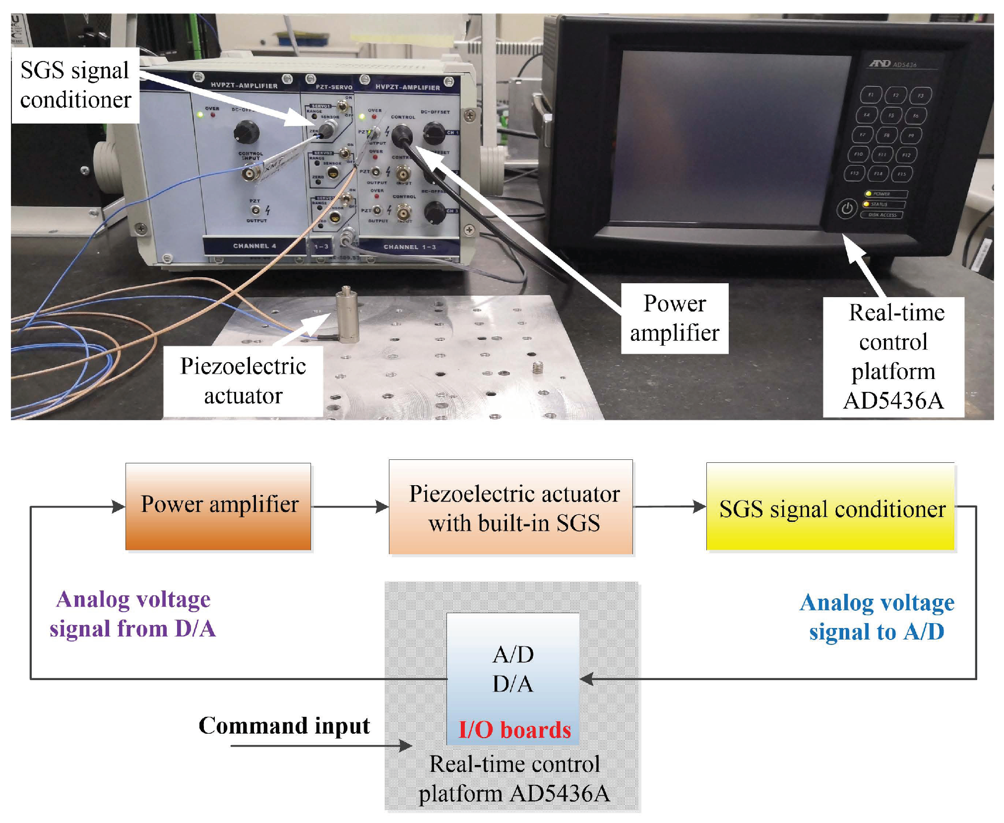
The experimental platform is mainly comprised of 4 parts: (1) piezoelectric actuator; (2) power amplifier; (3) strain gauge sensor (SGS) signal conditioner, and (4) real-time control platform (RTCP) AD5436A, as shown in Figure 1 (top). The stacked piezoelectric actuator 20VS12 to be modelled and feedforward controlled has a built-in SGS to monitor its displacement. The nominal travel range of the piezoelectric actuator is 16 m and the piezoelectric actuator is fixed on an optical vibration isolation platform for rejecting external vibrational disturbance. The power amplifier XE-503.00 can amplify the input 0∼10 V analog voltage by 15 times and output 0∼150 V analog voltage with an average power of 7 W to excite the piezoelectric actuator. The SGS signal conditioner XE-509.S3 converts the signal generated from SGS into 0∼10 V analog voltage with a 0.1% nonlinearity. The piezoelectric actuator, power amplifier and SGS signal conditioner are all manufactured by Harbin Core Tomorrow Science and Technology Co., Ltd. in China. The RTCP AD5436A consists of an Intel Core i7-610E 2.53 GHz dual-Core CPU, 16 bits A/D and 16 bits D/A converter I/O boards. It is used for high-speed measurement of the displacement and rapid control prototyping for feedforward control of the piezoelectric actuator. As illustrated in Figure 1 (bottom), the experimental schematic diagram shows the signal flow of the main components of the experimental platform.
3.2. Model Identification
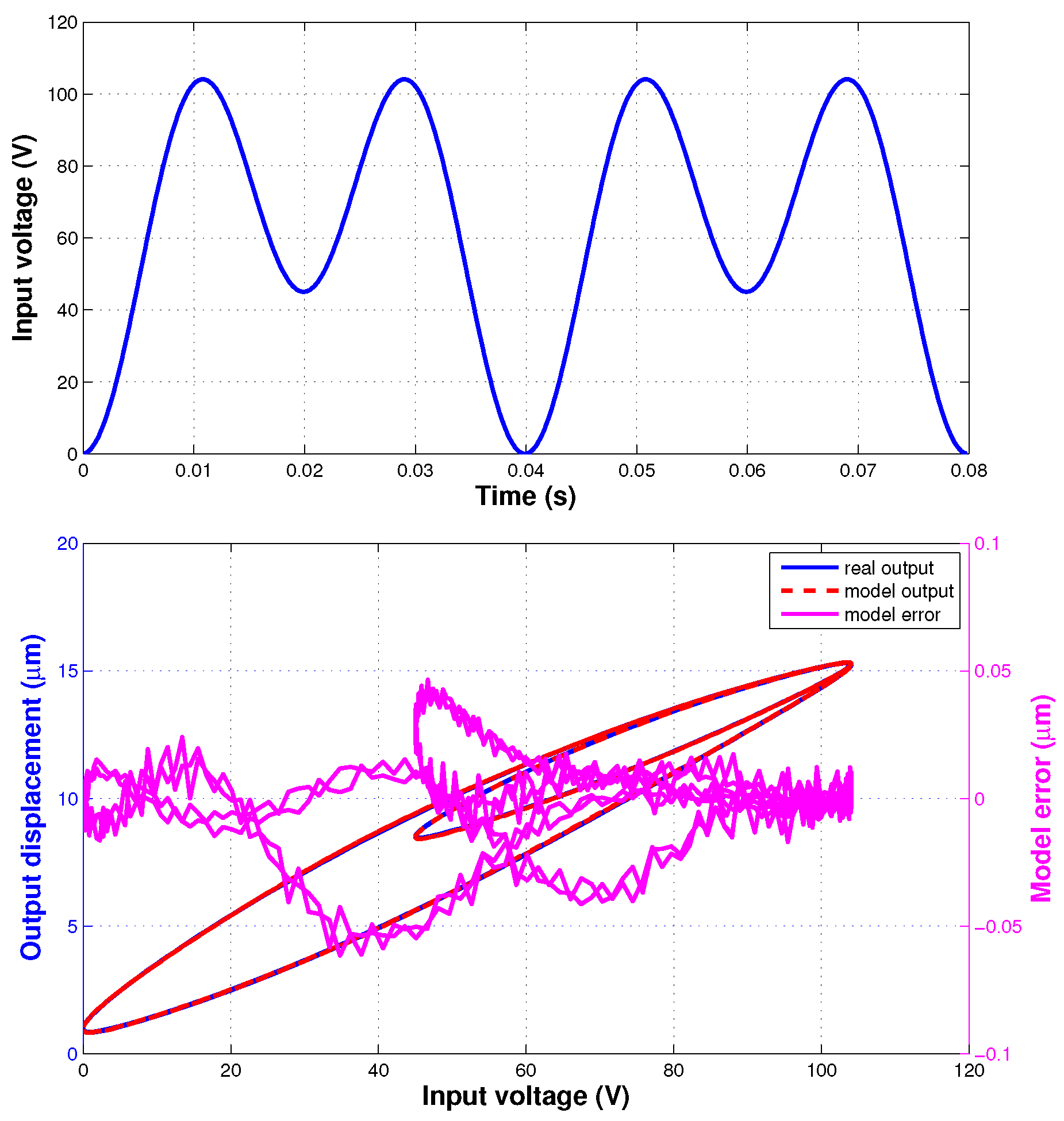
As shown in Figure 2 (top), the input voltage signal used for the hysteresis model identification of the IT2 fuzzy system is described with the following function
where s means that the sampling frequency is 10 kHz. The signal is the sum of 2 different sinusoidal profiles with 50 Hz and 25 Hz frequencies.
The cost function for optimization is defined as
where N is the number of the sampled data. The input and output of the piezoelectric actuator are extended as a vector . The vector is then used for the IT2 fuzzy system to model the hysteresis.
Hysteresis model identification of the proposed IT2 fuzzy system can be executed as follows:
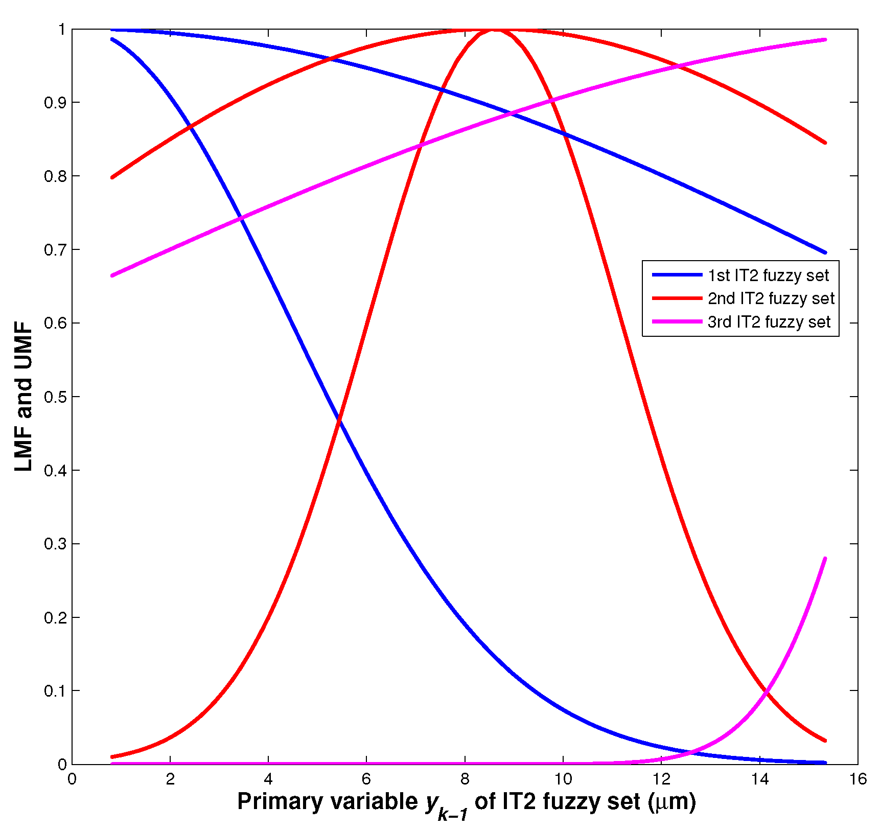
The identified parameters of IT2 fuzzy system are listed in Table 1. The LMF and UMF of the identified IT2 fuzzy sets are shown in Figure 3.
To evaluate the modelling performance, 2 types of error index are defined as:
Figure 2(bottom) presents the identification result of the proposed hysteresis model. The and are 0.42% and 0.016 m, respectively.
3.3. Model Validation
To validate the identified model, the following input voltage signals of different profiles are used:
where and are the frequencies of the sinusoidal and triangular signals, respectively, and is the period number of the triangular signal.
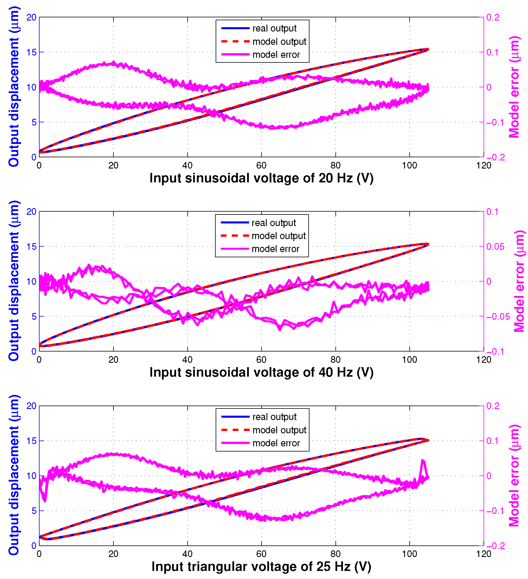
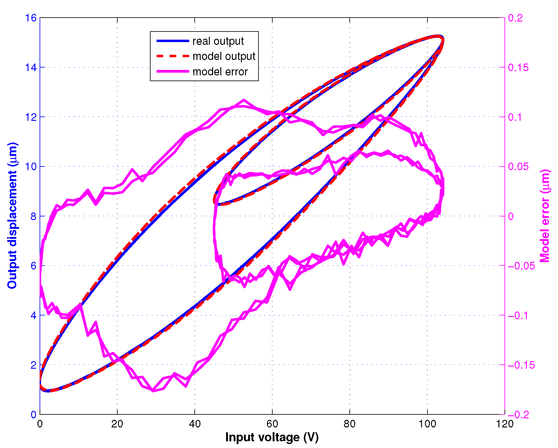
In the model validation experiments, totally 4 different input signals were used to excite the piezoelectric actuator and the corresponding displacement was measured. These input signals consist of two sinusoidal signals of (26) with Hz or 40 Hz, a triangular signal of (27) with Hz and a signal which is the sum of 2 different sinusoidal profiles with 100 Hz and 50 Hz frequencies. The validation results of the identified hysteresis model are shown in Figure 4 and Figure 5. The modelling errors are presented in Table 2. These results demonstrate the generalization performance of the developed IT2 fuzzy hysteresis model.
The hysteresis model is firstly identified based on the measured data of the piezoelectric actuator under the excitatory input voltage for identification of (22). Then, the generalization performance of the identified model (its identified parameters are listed in Table 1) is validated by using other different sampled data under the excitatory input voltages for validation of (26) and (27).
3.4. Feedforward Control
Compared with feedback control, feedforward control does not indispensably need the expensive sensor for its practical implementation. It is suitable for the applications where the sensor is not feasible or easy to be deployed for directly monitoring the plant or where the cost is a top priority and strictly limited. The plant’s model and especially its inverse are generally needed for the feedforward control.
Based on (10), the equation can be rewritten as
Then, it can be transposed as
Hence, the analytic inverse, , of the proposed hysteresis model based on IT2 fuzzy system is
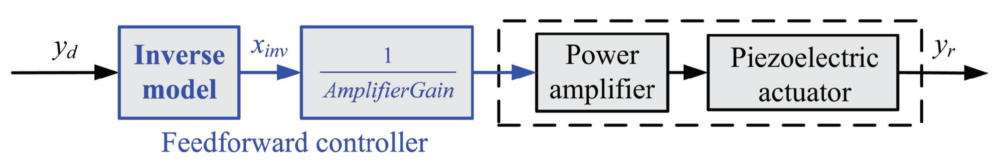
An open-loop feedforward controller is designed for the piezoelectric actuator based on the inverse model of (30) as shown in Figure 6. In the practical experiment, based on rapid control prototyping, this feedforward controller was implemented by the RTCP AD5436A under the real-time Xenomai operating system. The servo period was 0.1 ms, whose value is equal to the value of the sampling period of (22).
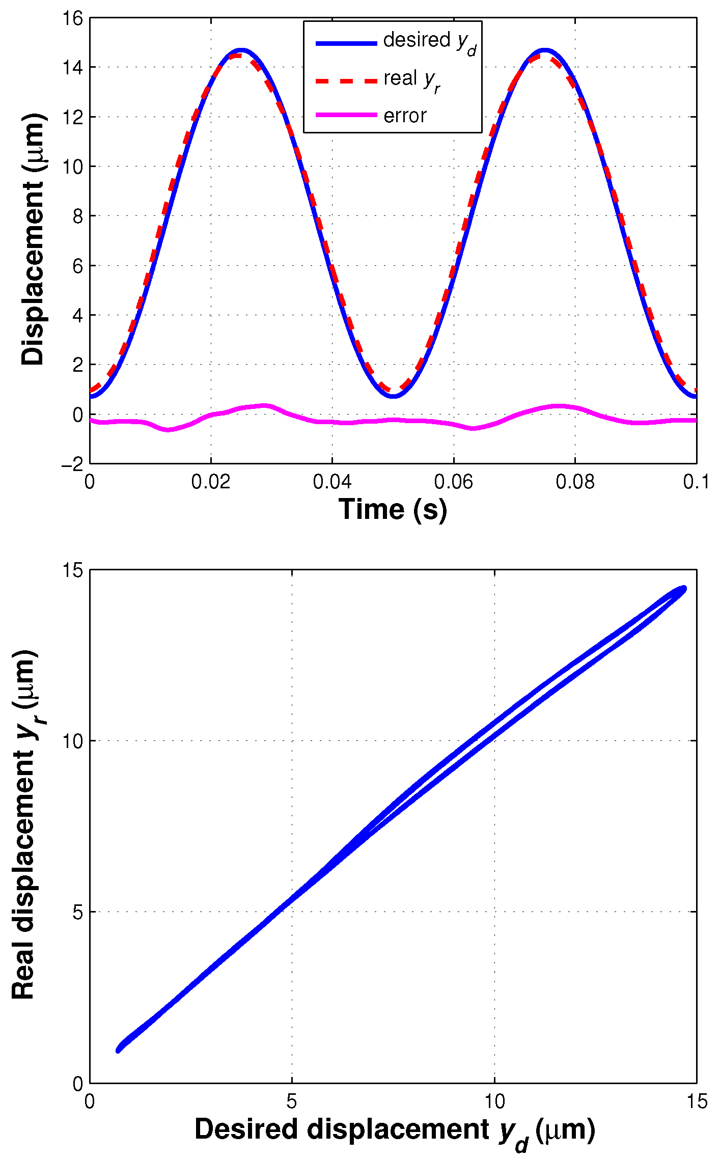
The desired displacement was chosen as m, whose frequency is 20 Hz. The tracking performance of the feedforward controller based on the inverse model of the developed IT2 fuzzy system is shown in Figure 7. The and of the sinusoidal trajectory tracking are 0.32 m and 4.6%, respectively, and the hysteresis effect of the piezoelectric actuator was significantly compensated. When there is no such inverse model applied, of a proportional feedforward controller can be 12.8%. Hence, the proposed feedforward controller has a good performance of tracking sinusoidal trajectory and compensating hysteresis of the piezoelectric actuator.
4. Conclusions
With analytic gradient and inverse, a simplified IT2 fuzzy system was developed for hysteresis modelling and feedforward control of the piezoelectric actuator. Experimental results demonstrated excellent performance of the proposed IT2 fuzzy system with only 3 fuzzy rules. Future work will involve: (1) other optimization methods such as evolutionary computation and neural networks for identifying the parameters of IT2 fuzzy system, and (2) feedback control algorithm incorporating the inverse model of IT2 fuzzy system.
Author Contributions
All of the authors have contributed substantially to this work, either in the implementations or in the writing of this article. B.L. and F.A. managed this work; P.-Z.L. and D.-F.Z. performed the experiments; J.-Y.H. analyzed the data; P.-Z.L. wrote the paper. All authors have read and agreed to the published version of the manuscript.
Funding
This research was funded by the UK Engineering and Physical Sciences Research Council (EPSRC) RAIN (EP/R026084/1) and RNE (EP/P01366X/1) projects.
Acknowledgments
This work was supported by the UK EPSRC projects RAIN (EP/R026084/1), RNE (EP/P01366X/1), and EPSRC-IAA Secondment Scheme. The authors also gratefully acknowledge the help and support from Forth Engineering in Cumbria.
Conflicts of Interest
The authors declare no conflict of interest.
Abbreviations
The following abbreviations are used in this manuscript:
| IT2 | Interval type-2 |
| MF | Membership function |
| FOU | Footprint of uncertainty |
| LMF | Lower membership function |
| UMF | Upper membership function |
| T-S | Takagi-Sugeno |
| SGS | Strain gauge sensor |
| RTCP | Real-time control platform |
References
- Li, P.Z.; Wang, X.D.; Zhao, L.; Zhang, D.F.; Guo, K. Dynamic linear modeling, identification and precise control of a walking piezo-actuated stage. Mech. Syst. Signal Process. 2019, 128, 141–152. [Google Scholar] [CrossRef]
- Zhang, D.F.; Li, P.Z.; Zhang, J.G.; Chen, H.N.; Guo, K.; Ni, M.Y. Design and Assessment of a 6-DOF Micro/Nanopositioning System. IEEE/ASME Trans. Mechatron. 2019, 24, 2097–2107. [Google Scholar] [CrossRef] [Green Version]
- Li, P.Z.; Wang, X.D.; Sui, Y.X.; Zhang, D.F.; Wang, D.F.; Dong, L.J.; Ni, M.Y. Piezoelectric actuated phase shifter based on external laser interferometer: Design, control and experimental validation. Sensors 2017, 17, 838. [Google Scholar] [CrossRef] [Green Version]
- Rakotondrabe, M. (Ed.) Smart Materials-Based Actuators at the Micro/Nano-Scale: Characterization, Control, and Applications; Springer: Berlin, Germany, 2013. [Google Scholar]
- Omidbeike, M.; Teo, Y.R.; Yong, Y.K.; Fleming, A.J. Tracking Control of a Monolithic Piezoelectric Nanopositioning Stage using an Integrated Sensor. IFAC Pap. 2017, 50, 10913–10917. [Google Scholar] [CrossRef]
- Lai, L.J.; Gu, G.Y.; Li, P.Z.; Zhu, L.M. Design of a decoupled 2-DOF translational parallel micro-positioning stage. In Proceedings of the 2011 IEEE International Conference on Robotics and Automation, Shanghai, China, 9–13 May 2011; pp. 5070–5075. [Google Scholar]
- Pons, J.; Rocon, E.; Forner-Cordero, A.; Moreno, J. Biomedical instrumentation based on piezoelectric ceramics. J. Eur. Ceram. Soc. 2007, 27, 4191–4194. [Google Scholar] [CrossRef]
- Ma, H.; Chen, R.; Hsu, Y. Development of a piezoelectric-driven miniature pump for biomedical applications. Sens. Actuators A Phys. 2015, 234, 23–33. [Google Scholar] [CrossRef]
- Lee, H.J.; Zhang, S.; Bar-Cohen, Y.; Sherrit, S. High Temperature, High Power Piezoelectric Composite Transducers. Sensors 2014, 14, 14526–14552. [Google Scholar] [CrossRef] [Green Version]
- Sahu, B.; Ahuja, R.; Kumar, R.; Suman, S.; Mathuria, D.; Rai, A.; Patra, P.; Pandey, A.; Karmakar, J.; Chowdhury, G.; et al. Piezoelectric actuator based phase locking system to improve the dynamics of the control scheme for a heavy ion superconducting linac. Nucl. Instrum. Methods Phys. Res. A 2015, 777, 123–130. [Google Scholar] [CrossRef]
- Bezryadina, A.S.; Preece, D.C.; Chen, J.C.; Chen, Z. Optical disassembly of cellular clusters by tunable ‘tug-of-war’ tweezers. Light. Sci. Appl. 2016, 5, e16158. [Google Scholar] [CrossRef]
- Chen, X.; Chardin, C.; Makles, K.; Caër, C.; Chua, S.; Braive, R.; Robert-Philip, I.; Briant, T.; Cohadon, P.F.; Heidmann, A.; et al. High-finesse Fabry—Perot cavities with bidimensional Si3N4 photonic-crystal slabs. Light. Sci. Appl. 2016, 6, e16190. [Google Scholar] [CrossRef] [Green Version]
- Zhou, Z.Y.; Li, Y.; Ding, D.S.; Zhang, W.; Shi, S.; Shi, B.S.; Guo, G.C. Orbital angular momentum photonic quantum interface. Light. Sci. Appl. 2016, 5, e16019. [Google Scholar] [CrossRef] [PubMed] [Green Version]
- Krejci, P.; Kuhnen, K. Inverse control of systems with hysteresis and creep. IEE Proc. Control Theory Appl. 2001, 148, 185–192. [Google Scholar] [CrossRef] [Green Version]
- Janaideh, M.A.; Krejci, P. Inverse Rate-Dependent Prandtl-Ishlinskii Model for Feedforward Compensation of Hysteresis in a Piezomicropositioning Actuator. IEEE/ASME Trans. Mechatron. 2013, 18, 1498–1507. [Google Scholar] [CrossRef]
- Rakotondrabe, M. Multivariable classical Prandtl-Ishlinskii hysteresis modeling and compensation and sensorless control of a nonlinear 2-dof piezoactuator. Nonlinear Dyn. 2017, 89, 481–499. [Google Scholar] [CrossRef]
- Janaideh, M.A.; Rakotondrabe, M.; Al-Darabsah, I.; Aljanaideh, O. Internal model-based feedback control design for inversion-free feedforward rate-dependent hysteresis compensation of piezoelectric cantilever actuator. Control Eng. Pract. 2018, 72, 29–41. [Google Scholar] [CrossRef]
- Davino, D.; Visone, C.; Ambrosino, C.; Campopiano, S.; Cusano, A.; Cutolo, A. Compensation of hysteresis in magnetic field sensors employing Fiber Bragg Grating and magneto-elastic materials. Sens. Actuators A Phys. 2008, 147, 127–136. [Google Scholar] [CrossRef]
- Song, G.; Zhao, J.; Zhou, X.; Abreu-Garcia, J.A.D. Tracking control of a piezoceramic actuator with hysteresis compensation using inverse Preisach model. IEEE/ASME Trans. Mechatron. 2005, 10, 198–209. [Google Scholar] [CrossRef]
- Oh, J.; Bernstein, D.S. Semilinear Duhem model for rate-independent and rate-dependent hysteresis. IEEE Trans. Autom. Control 2005, 50, 631–645. [Google Scholar]
- Li, P.Z.; Yan, F.; Ge, C.; Zhang, M.C. Ultra-precise tracking control of piezoelectric actuators via a fuzzy hysteresis model. Rev. Sci. Instrum. 2012, 83, 085114. [Google Scholar] [CrossRef]
- Li, P.Z.; Gu, G.Y.; Lai, L.J.; Zhu, L.M. Hysteresis modeling of piezoelectric actuators using the fuzzy system. In Proceedings of the 3rd International Conference on Intelligent Robotics and Applications, LNAI, Shanghai, China, 10–12 November 2010; Volume 6424, pp. 114–124. [Google Scholar]
- Ayala, H.V.H.; Habineza, D.; Rakotondrabe, M.; Klein, C.E.; Coelho, L.S. Nonlinear Black-box System Identification through Neural Networks of a Hysteretic Piezoelectric Robotic Micromanipulator. IFAC-PapersOnLine 2015, 48, 409–414. [Google Scholar] [CrossRef]
- De Rozario, R.; Fleming, A.J.; Oomen, T. Finite-Time Learning Control Using Frequency Response Data With Application to a Nanopositioning Stage. IEEE/ASME Trans. Mechatron. 2019, 24, 2085–2096. [Google Scholar] [CrossRef]
- De Rozario, R.; Fleming, A.J.; Oomen, T. Iterative Control for Periodic Tasks with Robustness Considerations, Applied to a Nanopositioning Stage. IFAC-PapersOnLine 2016, 49, 623–628. [Google Scholar] [CrossRef]
- Li, P.Z.; Yan, F.; Ge, C. Open-closed loop iterative learning control of piezoelectric actuators. Opt. Precis. Eng. 2014, 22, 414–419. [Google Scholar]
- Li, P.Z.; Li, P.Y.; Sui, Y.X. Adaptive fuzzy hysteresis internal model tracking control of piezoelectric actuators with nanoscale application. IEEE Trans. Fuzzy Syst. 2016, 24, 1246–1254. [Google Scholar] [CrossRef]
- Mendel, J.M. Uncertain Rule-Based Fuzzy Systems: Introduction and New Directions, 2nd ed.; Springer: Berlin, Germany, 2017. [Google Scholar]
- Mendel, J.M. Comparing the Performance Potentials of Interval and General Type-2 Rule-Based Fuzzy Systems in Terms of Sculpting the State Space. IEEE Trans. Fuzzy Syst. 2019, 27, 58–71. [Google Scholar] [CrossRef]
- Tang, X.; Deng, L.; Qu, H. Predictive Control for Networked Interval Type-2 T-S Fuzzy System via an Event-Triggered Dynamic Output Feedback Scheme. IEEE Trans. Fuzzy Syst. 2019, 27, 1573–1586. [Google Scholar] [CrossRef]
- Wu, D.; Mendel, J.M. Designing Practical Interval Type-2 Fuzzy Logic Systems Made Simple. In Proceedings of the 2014 IEEE International Conference on Fuzzy Systems, Beijing, China, 6–11 July 2014. [Google Scholar]
- Wu, H.; Liu, Z.; Zhang, Y.; Chen, C.L.P. Adaptive Fuzzy Output Feedback Quantized Control for Uncertain Nonlinear Hysteretic Systems Using a New Feedback-Based Quantizer. IEEE Trans. Fuzzy Syst. 2019, 27, 1738–1752. [Google Scholar] [CrossRef]
- Rubio-Solis, A.; Melin, P.; Martinez-Hernandez, U.; Panoutsos, G. General Type-2 Radial Basis Function Neural Network: A Data-Driven Fuzzy Model. IEEE Trans. Fuzzy Syst. 2019, 27, 333–347. [Google Scholar] [CrossRef] [Green Version]
- Bayat, S.; Pishkenari, H.N.; Salarieh, H. Observer design for a nano-positioning system using neural, fuzzy and ANFIS networks. Mechatronics 2019, 59, 10–24. [Google Scholar] [CrossRef]
- Takagi, T.; Sugeno, M. Fuzzy identification of systems and its applications to modeling and control. IEEE Trans. Syst. Man Cybern. 1985, 1, 116–132. [Google Scholar] [CrossRef]
- Nie, M.; Tan, W.W. Towards an efficient type-reduction method for interval type-2 fuzzy logic systems. In Proceedings of the 2008 IEEE International Conference on Fuzzy Systems, Hong Kong, China, 1–6 June 2008. [Google Scholar]
- Mendel, J.M. On KM algorithms for solving type-2 fuzzy set problems. IEEE Trans. Fuzzy Syst. 2013, 21, 426–446. [Google Scholar] [CrossRef]
Figure 1.
Experimental platform: (top) main hardware including piezoelectric actuator, power amplifier, strain gauge sensor signal conditioner, and real-time control platform AD5436A, (bottom) signal flow.
Figure 1.
Experimental platform: (top) main hardware including piezoelectric actuator, power amplifier, strain gauge sensor signal conditioner, and real-time control platform AD5436A, (bottom) signal flow.

Figure 2.
Model Identification: (top) input voltage signal, (bottom) identification result and error.
Figure 2.
Model Identification: (top) input voltage signal, (bottom) identification result and error.

Figure 3.
LMF and UMF of the identified IT2 fuzzy sets.

Figure 4.
Validation results of the identified hysteresis model under different input signals: (top) 20 Hz sinusoidal, (center) 40 Hz sinusoidal, and (bottom) 25 Hz triangular.
Figure 4.
Validation results of the identified hysteresis model under different input signals: (top) 20 Hz sinusoidal, (center) 40 Hz sinusoidal, and (bottom) 25 Hz triangular.

Figure 5.
Validation results of the identified hysteresis model under the signal which is the sum of 2 different sinusoidal profiles with 100 Hz and 50 Hz frequencies.
Figure 5.
Validation results of the identified hysteresis model under the signal which is the sum of 2 different sinusoidal profiles with 100 Hz and 50 Hz frequencies.

Figure 6.
Block diagram of feedforward controller.

Figure 7.
Tracking performance of feedforward controller: (top) tracking results, (bottom) hysteresis compensation result.
Figure 7.
Tracking performance of feedforward controller: (top) tracking results, (bottom) hysteresis compensation result.


Table 1.
Identified parameters of IT2 fuzzy system.
| Rule | Antecedent Parameters | Consequent Parameters |
|---|---|---|
| 1 | (4.3427, 17.8879, 0.0892) | (0.8943, 0.0196, 1.7504) |
| 2 | (2.5647, 11.5798, 8.6067) | (0.9140, 0.0129, 0.8773) |
| 3 | (2.1349, 19.8162, 18.7381) | (1.1882, 0.0148, −6.2312) |
© 2020 by the authors. Licensee MDPI, Basel, Switzerland. This article is an open access article distributed under the terms and conditions of the Creative Commons Attribution (CC BY) license (http://creativecommons.org/licenses/by/4.0/).
Share and Cite
MDPI and ACS Style
Li, P.-Z.; Zhang, D.-F.; Hu, J.-Y.; Lennox, B.; Arvin, F. Hysteresis Modelling and Feedforward Control of Piezoelectric Actuator Based on Simplified Interval Type-2 Fuzzy System. Sensors 2020, 20, 2587. https://doi.org/10.3390/s20092587
AMA Style
Li P-Z, Zhang D-F, Hu J-Y, Lennox B, Arvin F. Hysteresis Modelling and Feedforward Control of Piezoelectric Actuator Based on Simplified Interval Type-2 Fuzzy System. Sensors. 2020; 20(9):2587. https://doi.org/10.3390/s20092587
Chicago/Turabian StyleLi, Peng-Zhi, De-Fu Zhang, Jun-Yan Hu, Barry Lennox, and Farshad Arvin. 2020. "Hysteresis Modelling and Feedforward Control of Piezoelectric Actuator Based on Simplified Interval Type-2 Fuzzy System" Sensors 20, no. 9: 2587. https://doi.org/10.3390/s20092587
Note that from the first issue of 2016, this journal uses article numbers instead of page numbers. See further details here.