A Patch/Dipole Hybrid-Mode Antenna for Sub-6GHz Communication


1
School of Materials and Energy, Guangdong University of Technology, Guangzhou 510006, China
2
School of Information Engineering, Guangdong University of Technology, Guangzhou 510006, China
*
Author to whom correspondence should be addressed.
Sensors 2019, 19(6), 1358; https://doi.org/10.3390/s19061358
Submission received: 6 February 2019
/
Revised: 10 March 2019
/
Accepted: 13 March 2019
/
Published: 18 March 2019
(This article belongs to the Special Issue Antenna Technologies for Microwave Sensors)
Abstract
:A low-profile antenna with a high gain and broad bandwidth is proposed for Sub-6GHz communication in this paper. A narrow-band patch mode and a narrow-band dipole mode are shared in one radiator and simultaneously excited to broaden the bandwidth. A compact prototype with a projection size of 0.90 λ0 × 0.78 λ0 and a profile of 0.13 λ0 (λ0 is the wavelength in the free space at the center of the operating frequency) is fabricated and measured. The measurement demonstrates an impedance bandwidth of 67.50%, covering the frequency range from 2.75 GHz to 5.45 GHz and an average gain of 8.4 dBi in the operating band of 3.0–5.0 GHz.
1. Introduction
Microstrip antennas are popular structures for a shared aperture due to their low mass and ability to be easily integrated with the feeding network [1], which are suitable for micro base station applications for persuasive fifth generation communication. Dipoles and microstrip patches were interlaced in [2] to realize a bandwidth of 8.9% in the S-band and 17.0% in the X-band, with a frequency ratio of 1:3. A dual-band dual-polarized antenna was introduced in [3], where a parasitic patch was stacked over a driven patch. In this way, each polarization could share one feeding network, which contributed to the reduction of the feeding networks and input ports. Therefore, the antenna had two operating bands, respectively covering the C-band from 5.05 to 5.30 GHz and the X-band from 9.60 to 10.30 GHz.
Both the patch and dipole have a small bandwidth within a limited profile. A common method is to shape the patch or slot for broadening the bandwidth. Two conventional quarter-wave patch antennas with an L-slit and U-slot were implemented and compared in [4], which achieved impedance bandwidths of 45.0% and 53.0%, with profiles of less than 0.13 λ0 and 0.11 λ0, respectively. Here, λ0 is the wavelength in the free space at the center of the operating frequency. However, an increase in bandwidth using slotting techniques is always at a sacrifice of antenna gain. Therefore, how to keep a large bandwidth and a high gain at the same time is an attractive issue for a compact element.
A magneto-electric (ME) dipole antenna was proposed in [5], where an obtuse-triangular structure was used as a magnetic dipole. The ME dipole could reduce the profile to 0.097 λ0, maintaining a stable gain of 9.2 ± 1.1 dBi and achieving an impedance bandwidth of 28.2%. Hybrid mode is another promising candidate through sequentially exciting the adjacent modes in the interested band [6]. Two adjacent modes could be simultaneously excited by a crossed bow-tie dipole and an octagonal-ring antenna [7]. It retains the advantages of a low profile, broad bandwidth, and stable radiation pattern.
Similarly, the hybrid mode with sidewalls for the lower ultra-wide band was proposed in [8], in which the patch mode and slot mode were sequentially excited in a shared aperture. This antenna could cover a frequency band from 3.00 to 4.99 GHz and maintain a minimum gain of 9.0 dBi with a projection area of 1.09 λ0 × 1.04 λ0 and a profile of 0.13 λ0.
This paper is an extension of the conference paper [9], where mode analysis is detailed to demonstrate the mode hybridization. In conjunction with a tapered feeding line, a broadband balun is designed to convert the single feeding to differential feeding. In this way, the complexity of the feeding method is reduced when compared with the hybrid mode antennas [7,8]. The low-cost substrate used can also help to reduce the cost of this antenna and therefore support the dense deployment for micro base station applications. The frequency bands of n77 (3300–4200 MHz), n78 (3300–3800 MHz), and n79 (4400–5000 MHz), specified by the Third Generation Partnership Project (3GPP) for 5G communication, are covered by the proposed antenna for Sub-6GHz communication [10].
2. Antenna Design and Analysis
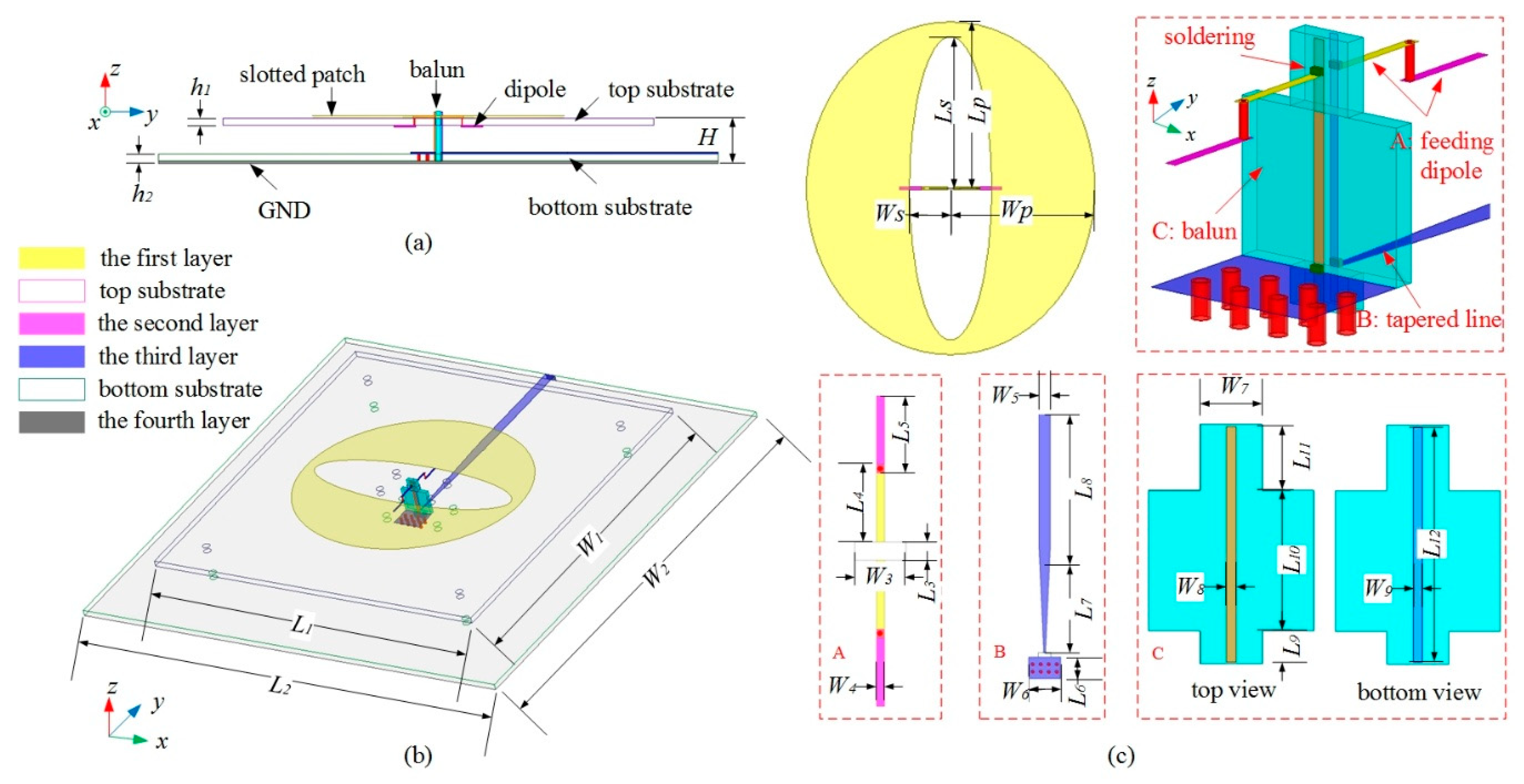
Figure 1 presents the geometry of the proposed antenna, which consists of an elliptical slotted patch, a feeding dipole connected with a broadband balun, and top and bottom substrates. The elliptical slotted patch is printed on the top side of the top substrate, which has been demonstrated to operate in an ultra-wideband for unidirectional radiation due to its tapered structure [11]. To ease the assembly and soldering, the feeding dipole is split into two parts on the top and bottom sides of the top substrate and these two parts are connected by the plating through holes. Two vertical parallel feeding lines, i.e., the balun structure, are designed to differentially excite the feeding dipole. The impedance transformation is implemented by a tapered line and printed on the top side of the bottom substrate. The ground plane is printed on the bottom side of the bottom substrate. All substrates used are FR4 materials.
Four parameters are used to describe the geometry of the slotted patch, namely, the halves of the long axis and short axis of the elliptical slot (LS, WS), and those of the elliptical patch (LP, WP). The elliptical patch is tuned to operate at its fundamental mode in the lower frequency band at its initial design. With an elliptical slot etched on its center, each arm of the feeding dipole has a length of about a quarter of the wavelength [8]. By properly selecting the value, the hybrid mode can be sequentially excited in the band of interest. The detailed dimensions of the proposed antenna are listed in Table 1. The sizes of the top and bottom substrates are 100 mm × 100 mm and 130 mm × 130 mm, respectively. The profile of the antenna is 10 mm.
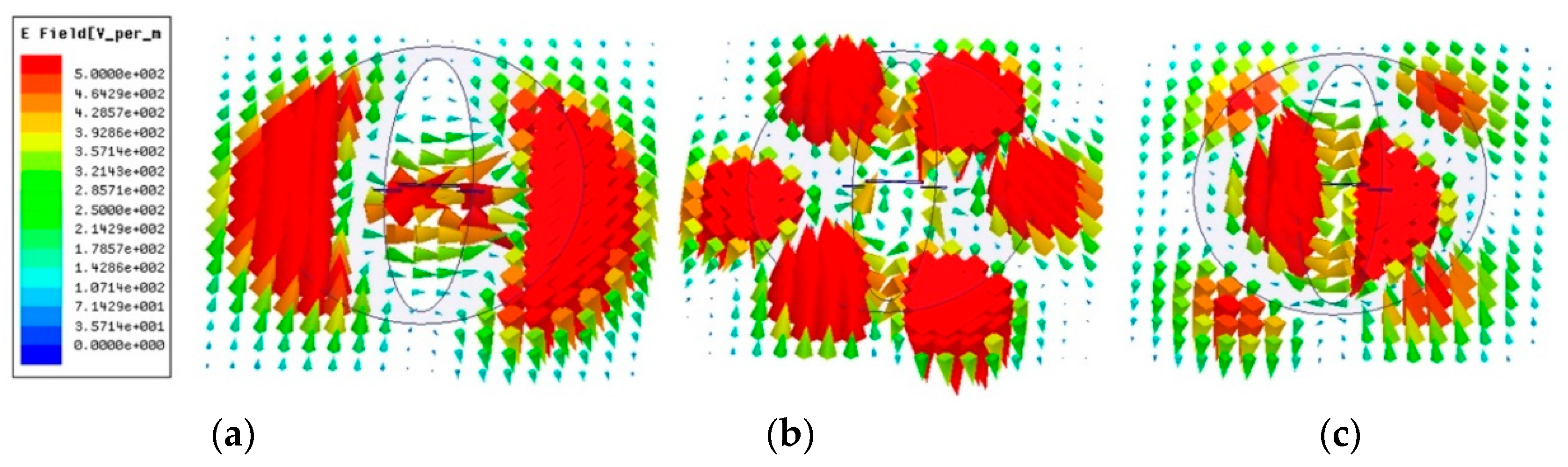
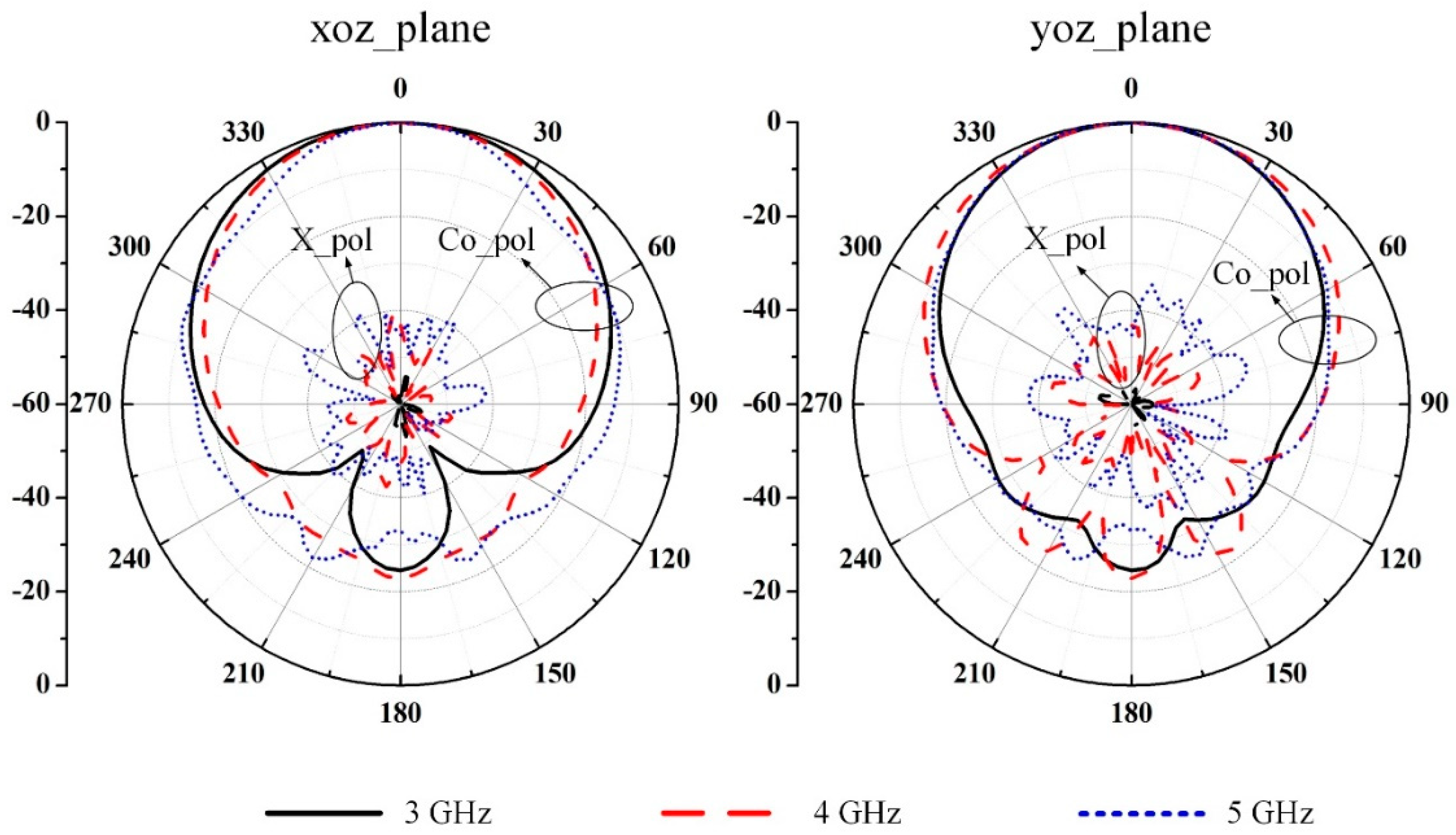
For better understanding the operation of the proposed antenna, the electric field distribution underneath the radiator is extracted and displayed in Figure 2. The feeding network and balun are removed for more distinct modes and the antenna is excited at the center of the feeding dipole. The port is excited with an identical unit input power throughout all frequencies. The same scale is shared on the left. It is found that the dipole plays an important role in the higher frequency region. The patch mode dominates the radiation over the operating frequency range. Additionally, the slotting technique in the center of the patch can help to suppress the cross-polarization level [12]. Figure 3 shows the simulated radiation patterns without the feeding network and balun. In the operating frequency band of 3.0 to 5.0 GHz, both xoz and yoz planes can maintain stable radiation patterns in terms of half-power beam-widths (HPBWs). More to the point, the HPBWs are 68.40°, 67.98°, and 58.36° in the xoz plane and 56.02°, 57.46°, and 41.62° in the yoz plane at 3.0, 4.0, and 5.0 GHz, respectively.
3. Results and Discussions
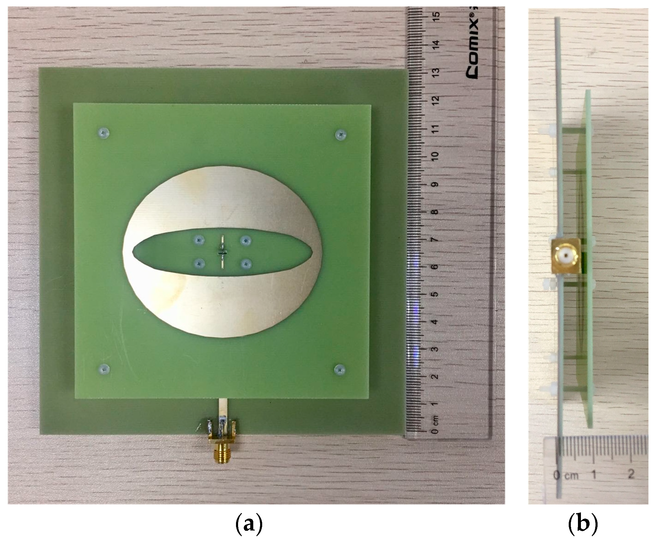
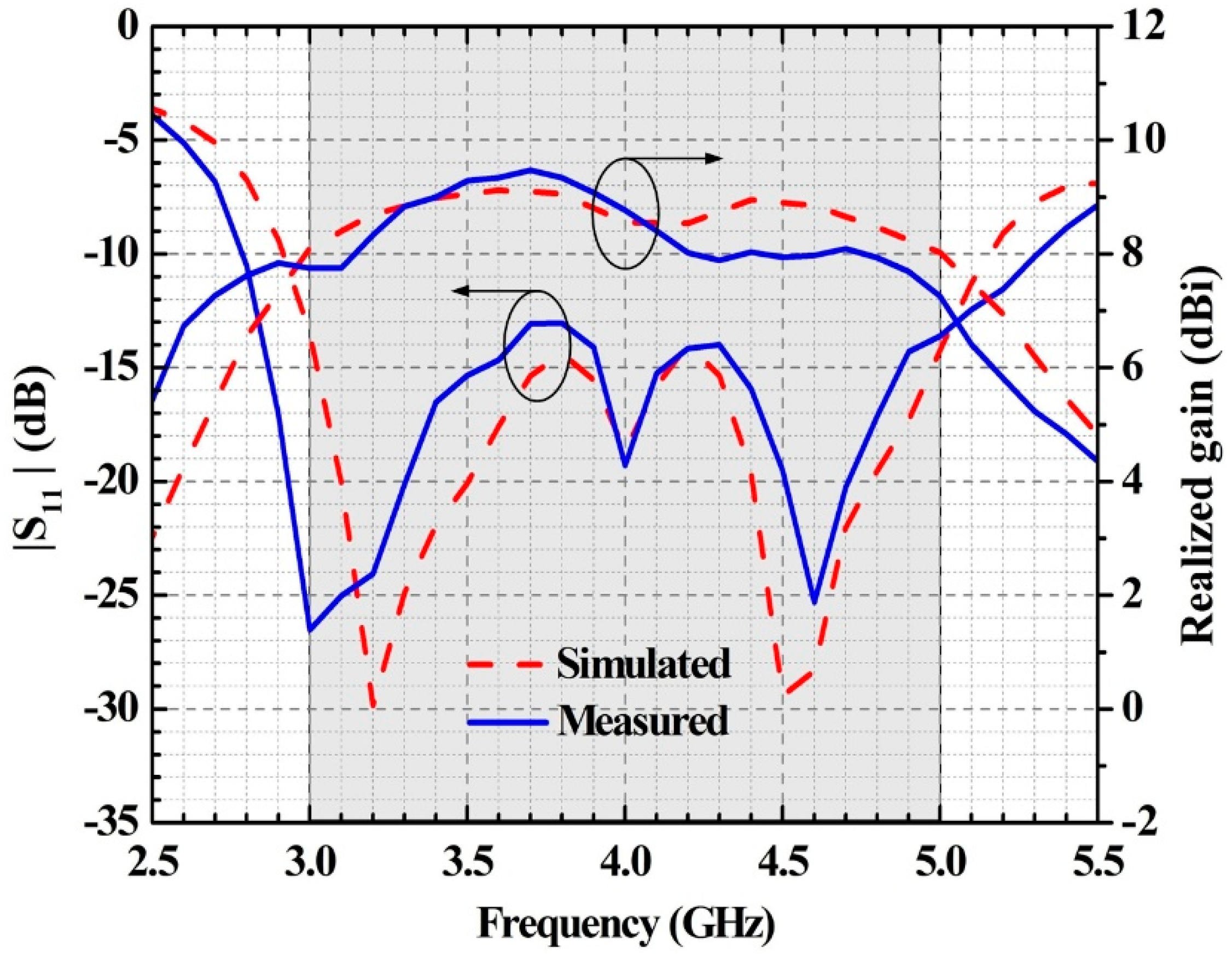
Figure 4 shows the photograph of the prototype antenna. Nylon screws are used to fix the top and bottom substrates. The reflection coefficients of the prototype are measured by the KEYSIGHT E5071C Vector Network Analyzer (Keysight Technology, New York, USA). The radiation patterns and gains are measured in an anechoic chamber. Figure 5 illustrates the simulated and measured reflection coefficients and broadside gains versus frequency. The simulated 10-dB impedance bandwidth is 55.75%, covering 2.92 GHz to 5.15 GHz. The measured 10-dB impedance bandwidth is 67.50% in the range of 2.75 GHz to 5.45 GHz. Therefore, the impedance bandwidth of the proposed antenna can cover the frequency bands of n77 (3300–4200 MHz), n78 (3300–3800 MHz), and n79 (4400–5000 MHz).
The simulated radiation efficiency of the proposed antenna varies from 70% to 80% within the operating band, where the minimum value is reached at 5.0 GHz. The simulated gain varies between 8.0 and 9.1 dBi with 1.1-dB variation, while the measured one varies between 7.3 and 9.5 dBi, with 2.2-dB variation. The discrepancies between the simulated and measured results can be attributed to fabrication and assembly errors.
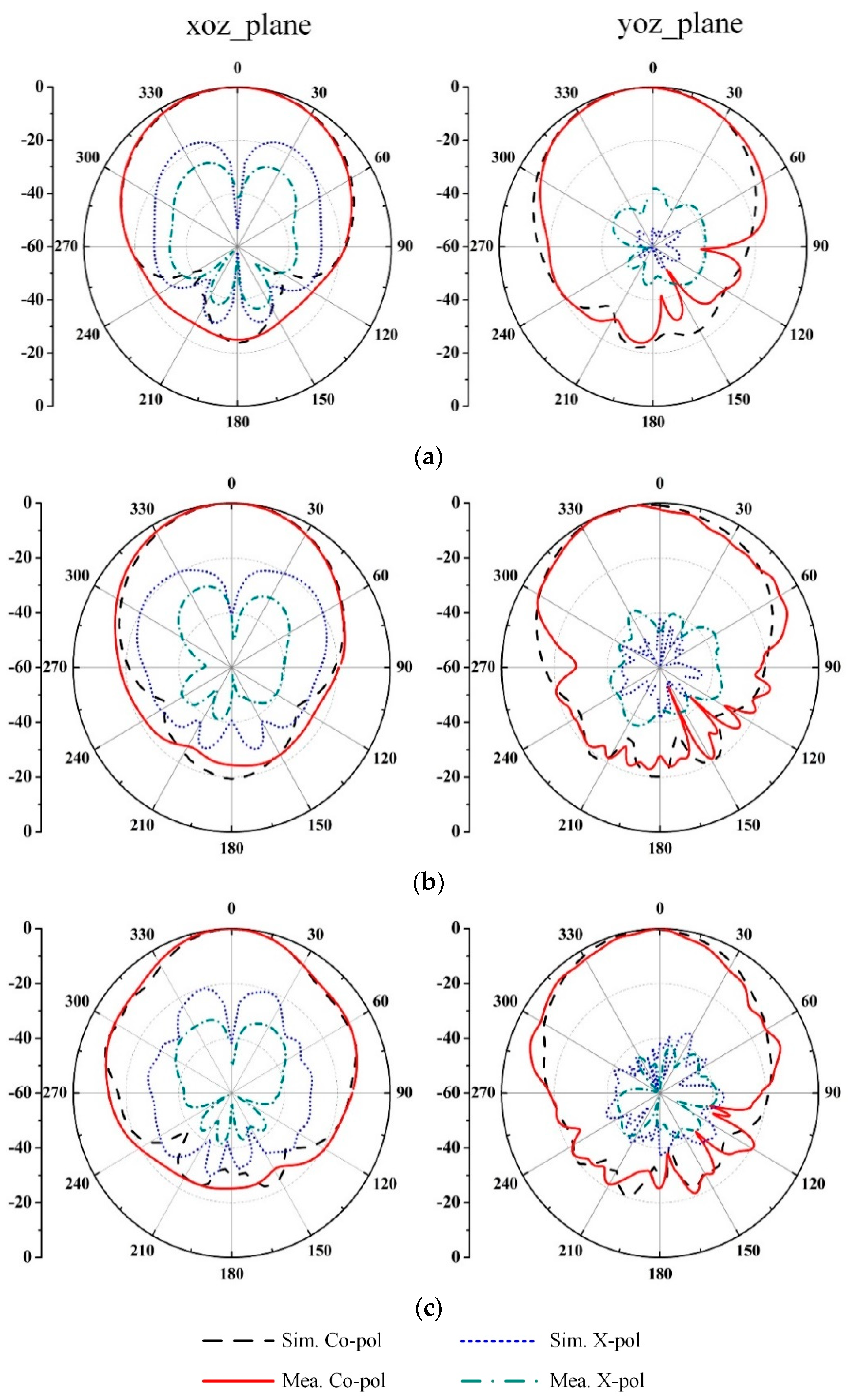
The radiation patterns of the prototype antenna at three typical frequencies are displayed in Figure 6. The measured radiation patterns in both xoz and yoz planes agree with the simulated ones. The HPBWs are 70.4°, 55.7°, and 43.2° in the xoz plane and 46.3°, 43.3°, and 40.5° in the yoz plane at 3.0 GHz, 4.0 GHz, and 5.0 GHz, respectively. However, the spurious radiation from the asymmetric balun [13] causes a slight shift of the main beam from the broadside direction in the yoz plane. Meanwhile, the polarization purity of the proposed antenna is deteriorated at the xoz plane. The simulated cross polarization in the worst case is less than −18.5 dB over the operating band, while the measured one is around −28.5 dB in the operating frequency band. The difference in the cross polarization may be caused by assembly and measurement errors.
A comparison of the proposed antenna and gain-bandwidth enhanced antennas in the literature is summarized in Table 2. Ref. [5] has a lower profile and higher antenna gain, but a narrower bandwidth. The reduction in the profile but increase in the size is obvious when compared with [14]. Though [15] and [16] have a much lower profile, the proposed antenna has a larger bandwidth or compacter size. Moreover, the radiation pattern in [16] has side lobes, which may cause the reduction in the directivity.
4. Conclusions
An elliptical patch/dipole antenna operating in a hybrid mode has been designed and investigated to simultaneously enhance the gain and bandwidth in a low profile. The bandwidth is about 67.50%, covering the frequency from 2.75 GHz to 5.45 GHz. An average gain of 8.40 dBi in the operating band of 3.0–5.0 GHz is achieved with a projection size of 0.90 λ0 × 0.78 λ0 and a profile of 0.13 λ0. The proposed antenna has a simple structure and low fabrication cost. The antenna may find its applications in the micro base station for Sub-6GHz communications. The distortion of the radiation pattern resulting from the spurious radiation of the balun [17] will be addressed in the future.
Author Contributions
Formal Analysis, B.H. and J.Z.; Investigation, W.L. and J.H.; Methodology, B.H. and J.Z.; Writing-Original Draft Preparation, B.H. and J.Z.; Writing-Review & Editing, G.Z and F.W.
Funding
This research was funded by the National Natural Science Foundation of China (NSFC) under Grant Numbers 61701120 and 61574049.
Conflicts of Interest
The authors declare no conflict of interest.
References
- Pozar, D.M.; Targonski, S.D. A Shared-Aperture Dual-Band Dual-Polarized Microstrip Array. IEEE Trans. Antennas Propag. 2001, 49, 150–157. [Google Scholar] [CrossRef]
- Qu, X.; Zhong, S.; Zhang, Y.; Wang, W. Design of an S/X dual-band dual-polarised microstrip antenna array for SAR applications. IET Microwav. Antennas Propag. 2007, 1, 513–517. [Google Scholar] [CrossRef]
- Mao, C.-X.; Gao, S.; Wang, Y.; Luo, Q.; Chu, Q.-X. A Shared-Aperture Dual-Band Dual-Polarized Filtering-Antenna-Array With Improved Frequency Response. IEEE Trans. Antennas Propag. 2017, 65, 1836–1844. [Google Scholar] [CrossRef]
- Chiu, C.Y.; Shum, K.M.; Chan, C.H.; Luk, K.M.; Kong, H. Bandwidth Enhancement Technique for Quarter-Wave Patch Antennas. IEEE Antennas Wirel. Propag. Lett. 2003, 2, 130–132. [Google Scholar] [CrossRef]
- Ding, C.; Luk, K.M. Low-Profile Magneto-Electric Dipole Antenna. IEEE Antennas Wirel. Propag. Lett. 2016, 15, 1642–1644. [Google Scholar] [CrossRef]
- Luo, G.; Hu, Z.; Li, W.; Zhang, X.; Sun, L.; Zheng, J. Bandwidth-Enhanced Low-Profile Cavity-Backed Slot Antenna by Using Hybrid SIW Cavity Modes. IEEE Trans. Antennas Propag. 2012, 60, 1698–1704. [Google Scholar] [CrossRef]
- Zhang, J.; Shen, Z. Dual-Band Shared-Aperture UHF/UWB RFID Reader Antenna of Circular Polarization. IEEE Trans. Antennas Propag. 2018, 66, 3886–3893. [Google Scholar] [CrossRef]
- Zhang, J.; Shen, Z. Compact and High-Gain UHF/UWB RFID Reader Antenna. IEEE Trans. Antennas Propag. 2017, 65, 5002–5010. [Google Scholar] [CrossRef]
- Huang, B.; Zhang, J.; Liu, Z.; Zhang, G.; Wu, F. Directed gain bandwidth enhancement in patch/slot hybrid antenna. In Proceedings of the Asia-Pacific Microwave Confenrence, Kyoto, Japan, 6–9 November 2018. [Google Scholar]
- Tang, H.; Zong, X.; Nie, Z. Broadband Dual-Polarized Base Station Antenna for Fifth-Generation (5G) Applications. Sensors 2018, 18, 2701. [Google Scholar] [CrossRef] [PubMed]
- Li, P.; Liang, J.; Chen, X. Study of Printed Elliptical/Circular Slot Antennas for Ultrawideband Applications. IEEE Trans. Antennas Propag. 2006, 54, 1670–1675. [Google Scholar] [CrossRef]
- Guha, D.; Biswas, M.; Antar, Y.M.M. Microstrip Patch Antenna with Defected Ground Structure for Cross Polarization Suppression. IEEE Antennas Wirel. Propag. Lett. 2005, 4, 455–458. [Google Scholar] [CrossRef]
- Mirmozafari, M.; Zhang, G.; Saeedi, S.; Doviak, R.J. A Dual Linear Polarization Highly Isolated Crossed Dipole Antenna for MPAR Application. IEEE Antennas Wirel. Propag. Lett. 2017, 16, 1879–1882. [Google Scholar] [CrossRef]
- Xue, Q.; Liao, S.; Xu, J. A Differentially-Driven Dual-Polarized Magneto-Electric Dipole Antenna. IEEE Trans. Antennas Propag. 2013, 61, 425–430. [Google Scholar] [CrossRef]
- Pan, Y.; Hu, P.; Zhang, X.; Zheng, S. A Low-Profile High-Gain and Wideband Filtering Antenna with Metasurface. IEEE Trans. Antennas Propag. 2016, 64, 2010–2016. [Google Scholar] [CrossRef]
- Liu, N.-W.; Zhu, L.; Choi, W.-W.; Zhang, J.-D. A Low-Profile Differentially Fed Microstrip Patch Antenna With Broad Impedance Bandwidth Under Triple-Mode Resonance. IEEE Antennas Wirel. Propag. Lett. 2018, 17, 1478–1482. [Google Scholar] [CrossRef]
- Vallecchi, A.; De Luis, J.R.; Capolino, F.; De Flaviis, F. Low Profile Fully Planar Folded Dipole Antenna on a High Impedance Surface. IEEE Trans. Antennas Propag. 2012, 60, 51–62. [Google Scholar] [CrossRef]
Figure 1.
Geometry of the proposed antenna (a) side view, (b) perspective view, and (c) zoom in (part A: the feeding dipole, part B: the tapered line, and part C: both sides of the balun).
Figure 1.
Geometry of the proposed antenna (a) side view, (b) perspective view, and (c) zoom in (part A: the feeding dipole, part B: the tapered line, and part C: both sides of the balun).

Figure 2.
The simulated electric field distribution of the proposed antenna without a feeding network and balun (remove the feeding network and balun, fed in the center of the feeding dipole by a lumped port) at (a) 3.0 GHz, (b) 4.0 GHz, and (c) 5.0 GHz.
Figure 2.
The simulated electric field distribution of the proposed antenna without a feeding network and balun (remove the feeding network and balun, fed in the center of the feeding dipole by a lumped port) at (a) 3.0 GHz, (b) 4.0 GHz, and (c) 5.0 GHz.

Figure 3.
Simulated radiation patterns of the proposed antenna without a feeding network and balun at (a) xoz plane and (b) yoz plane.
Figure 3.
Simulated radiation patterns of the proposed antenna without a feeding network and balun at (a) xoz plane and (b) yoz plane.

Figure 4.
Photograph of the antenna prototype: (a) top view and (b) side view.

Figure 5.
The simulated and measured reflection coefficients and realized gains of the proposed antenna.
Figure 5.
The simulated and measured reflection coefficients and realized gains of the proposed antenna.

Figure 6.
Simulated and measured radiation patterns of the proposed antenna at (a) 3.0 GHz, (b) 4.0 GHz, and (c) 5.0 GHz.
Figure 6.
Simulated and measured radiation patterns of the proposed antenna at (a) 3.0 GHz, (b) 4.0 GHz, and (c) 5.0 GHz.


Table 1.
Dimensions of the Proposed Antenna.
| Parameter | L1 | L2 | L3 | L4 | L5 | L6 | L7 | L8 | L9 | L10 | L11 | L12 | h1 | h2 |
| Value (mm) | 100.00 | 130.00 | 1.20 | 5.20 | 5.20 | 5.80 | 29.40 | 35.00 | 1.60 | 6.80 | 3.20 | 11.40 | 1.60 | 1.60 |
| Parameter | W1 | W2 | W3 | W4 | W5 | W6 | W7 | W8 | W9 | LS | WS | LP | WP | H |
| Value (mm) | 100.00 | 130.00 | 3.20 | 0.50 | 2.92 | 8.00 | 3.00 | 0.50 | 0.42 | 30.75 | 8.35 | 33.75 | 29.25 | 10.00 |
Table 2.
Comparison with Gain-Bandwidth Enhanced Antennas.
| Reference | Projection Size (λ0 × λ0) | Profile (λ0) | Bandwidth | Realized Gain (dBi) | Cross Polarization (dB) | Front-to-Back Ratio (dB) | HPBW (°) # | |
|---|---|---|---|---|---|---|---|---|
| xoz Plane | yoz Plane | |||||||
| [5] | 0.93 × 0.51 | 0.097 | 28.2% | 9.2 ± 1.1 | −24.0 | 13.0 | 42.0 | 46.0 |
| [14] | 0.62 × 0.62 | 0.24 | 68.0% | 8.1 ± 1.5 | −23.0 | 14.0 | 56.0 | 53.0 |
| [15] | 0.82 × 0.69 | 0.06 | 28.4% | 8.2 ± 0.9 | −25.0 | 13.0 | 40.0 | 44.2 |
| [16] | 1.02 × 1.31 | 0.06 | 55.0% | 7.0 ± 3.0 | −25.2 | 17.0 | 24.2 | 34.3 |
| This work | 0.90 × 0.78 | 0.13 | 67.5% | 8.4 ± 1.1 * | −28.5 | 26.5 | 55.7 | 43.3 |
# The value of the half-power beam-width (HPBW) is extracted at the center operating frequency; * The radiation performance is extracted from 3.0 GHz to 5.0 GHz.
© 2019 by the authors. Licensee MDPI, Basel, Switzerland. This article is an open access article distributed under the terms and conditions of the Creative Commons Attribution (CC BY) license (http://creativecommons.org/licenses/by/4.0/).
Share and Cite
MDPI and ACS Style
Huang, B.; Lin, W.; Huang, J.; Zhang, J.; Zhang, G.; Wu, F. A Patch/Dipole Hybrid-Mode Antenna for Sub-6GHz Communication. Sensors 2019, 19, 1358. https://doi.org/10.3390/s19061358
AMA Style
Huang B, Lin W, Huang J, Zhang J, Zhang G, Wu F. A Patch/Dipole Hybrid-Mode Antenna for Sub-6GHz Communication. Sensors. 2019; 19(6):1358. https://doi.org/10.3390/s19061358
Chicago/Turabian StyleHuang, Bei, Weifeng Lin, Jialu Huang, Jun Zhang, Gary Zhang, and Fugen Wu. 2019. "A Patch/Dipole Hybrid-Mode Antenna for Sub-6GHz Communication" Sensors 19, no. 6: 1358. https://doi.org/10.3390/s19061358
Note that from the first issue of 2016, this journal uses article numbers instead of page numbers. See further details here.