1. Introduction
Linear stages, which are expected to travel along a straight line and precisely stop at some prescribed positions, play a crucial role in the manufacturing field and measurement field [
1,
2,
3,
4]. However, due to the manufacturing imperfections and the assembling errors, the linear stage inherits six-degree-of-freedom (six-DOF) error motions, including three linear errors (positioning error, horizontal and vertical straightness errors) and three angular errors (pitch, yaw and roll errors). These geometric errors of the linear stage will seriously affect the accuracy of the manufactured parts process or measured results. Compensation of these error motions is an effective approach to achieve a high accuracy [
1,
3]. To implement the error compensation, the six-DOF error motions should be accurately detected.
A laser interferometer, with high measurement accuracy and a long measurement range, is the most popular measurement instrument to identify these error motions [
5,
6]. However, the laser interferometer can only measure a single error with a specified optical accessory each time, which is extraordinary time-consuming to complete all errors. A laser tracker, which can simultaneously measure multi-DOF error motions, is another instrument usually applied to measure the error motions [
7,
8]. However, its measurement accuracy is low. In addition, the high cost is another drawback of the laser interferometers and the laser trackers.
A variety of systems, which are capable of simultaneously measuring the multi-DOF error motions, have been developed [
1,
2,
9,
10,
11,
12,
13,
14,
15,
16,
17,
18,
19,
20]. Measurement systems based on interferometry, such as the grating diffraction interferometry [
9,
10] and the laser synesthetic wavelength interferometry [
2,
11], have achieved a linear displacement resolution better than sub-nanometer and an angular displacement resolution of approximately sub-arcsecond. However, the measurement systems always have a complex configuration and time-consuming alignment process. The measurement accuracy of those systems is dependent on the characteristics of the laser source. In comparison, the non-interferometry-based measurement systems have been verified to be superior to the interferometry-based measurement systems in many aspects, such as simple construction and large measurement range [
1,
12,
13,
14,
15,
16,
17,
18,
19,
20]. Therefore, they are widely used for measuring the error motions of precision machines, such as numerically controlled machine tool and coordinate measuring machine.
The laser source of the above-mentioned systems could be the He-Ne laser [
2,
10,
11,
12], fiber laser [
14,
15,
19,
20], laser diode [
9,
17], or commercial laser interferometer [
13,
16,
18]. However, no matter what kind of laser is adopted, there always exists the physical phenomenon of angular drift of the laser beam, which will influence the system’s measurement accuracy and repeatability. The common-path method is a feasible approach for compensating the errors induced by the laser beam drift in laser measurement system [
14,
21]. However, the common-path method makes the system complex and time-consuming for laser beam alignment. Different turning mirror mechanisms have also been proposed to actively compensate for this angular drift [
17,
22]. In our previous research on a four-DOF measurement system [
17], an active compensation method was developed to reduce the effect of the beam angular drift of the laser diode on the measurement accuracy. However, the four-DOF measurement system cannot measure the roll error of the linear stage and the measurement errors of the system, which significantly influence the system measurement accuracy, were not analyzed.
Additionally, photodetectors are widely selected as the error detectors in the above-mentioned laser measurement systems [
12,
13,
14,
15,
16,
17,
18,
19,
20]. The photodetector sensitivity is influenced by the laser diameter and intensity, which have relationships with the measurement distance along the laser propagation direction [
23]. Therefore, it is essential to compensate for the errors caused by the sensitivity variation of a photodetector, especially in the long-distance measurement. However, the compensation of photodetector sensitivity was not considered in the above-mentioned measurement system [
9,
10,
11,
12,
13,
14,
15,
16,
17,
18,
19,
20]. In our previous research, a mathematical model was proposed for compensating the sensitivity variation of photodetectors, which were used as straightness error detectors [
24]. However, it has not been verified whether this model can also compensate for the sensitivity variation of angular errors detectors.
Furthermore, since the stage is already equipped with a position sensor, either a linear scale or a rotary encoder, the stage’s positioning error can be easily obtained by the calibration with a commercial laser interferometer. Hence, from our point of view, a five-DOF error measuring system is adequate for each linear stage. Therefore, in this paper, a compact and low-cost laser measurement system (LMS) based on the principle of the laser collimation is proposed to simultaneously measure two straightness errors and three angular errors of linear stages, whose travel distance is larger than one meter. As mentioned above, there are some errors that would influence the accuracy of the LMS, including the laser beam drift, the photodetector sensitivity variation, dual-beam non-parallelism, and crosstalk errors. In addition to the integration of error compensation schemes that have been considered in our previous four-DOF [
17] and roll measurement systems [
24], the elimination of overall crosstalk errors is further considered and analyzed in detail in this report. This five-DOF LMS is designed in modular type, including the sensor head and the detecting part. Differ from the above-mentioned multi-DOF measurement systems that the sensor head and the detecting part are mounted on the base of the stage at the same side [
14,
19,
20,
21], the detecting part of this LMS is directly mounted on the moving stage so as to reduce the laser path distance induced errors. Additionally, a wireless transmission kit is applied in the electronic unit of the system, making the LMS is suitable for on-machine measurement. Based on the analyzed results, the compensation methods are proposed, and the measurement model is modified, which makes the LMS robust and precise.
3. Testing of the Designed LMS
A laboratory-built prototype of the LMS was constructed to measure the five-DOF error motions of a linear stage based on the described measurement principles and compensation principles.
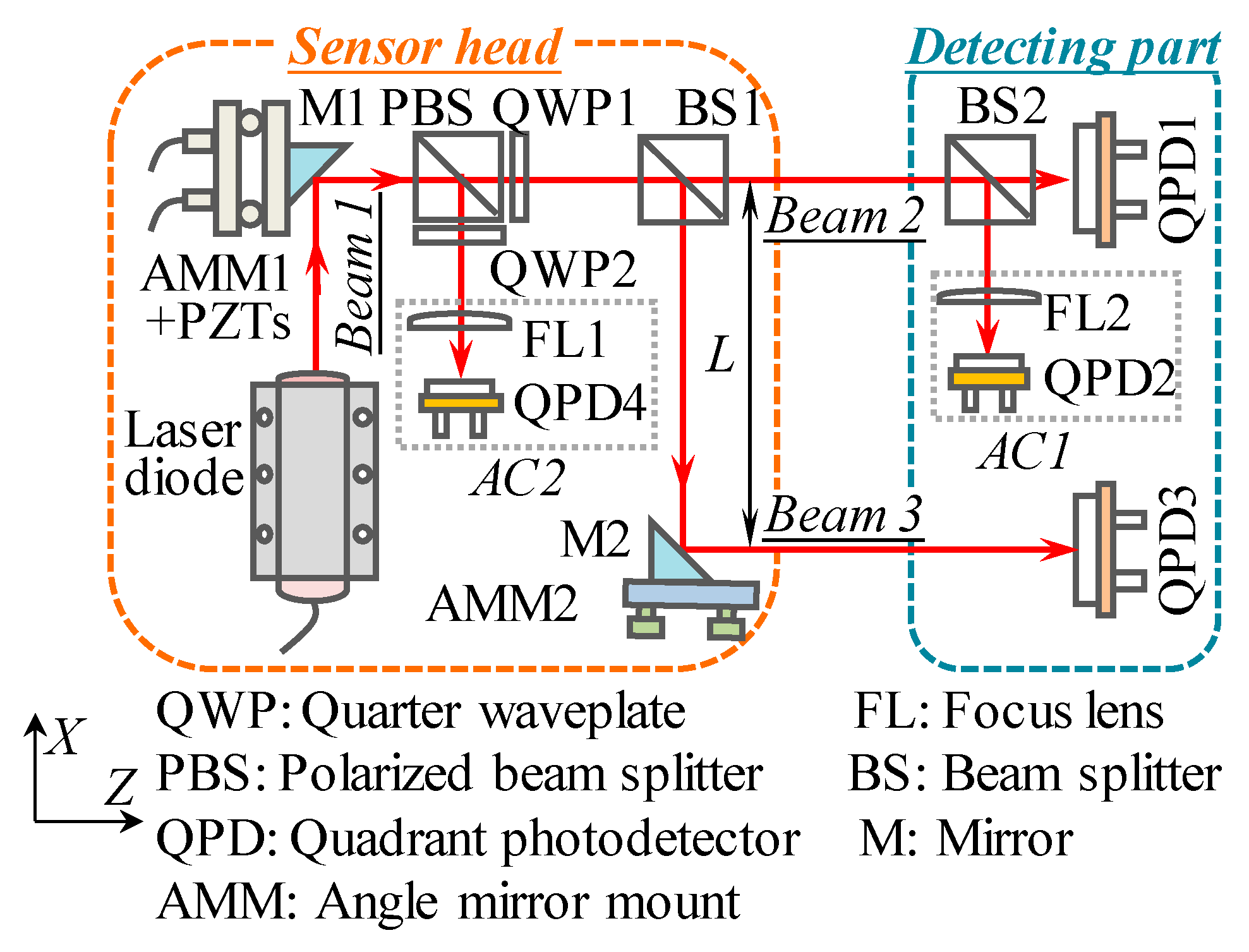
A collimated laser beam emitted from a low-cost laser diode (DA635, Huanic, China) has a diameter of 5 mm and a divergence angle less than 0.2 mrad. The distance
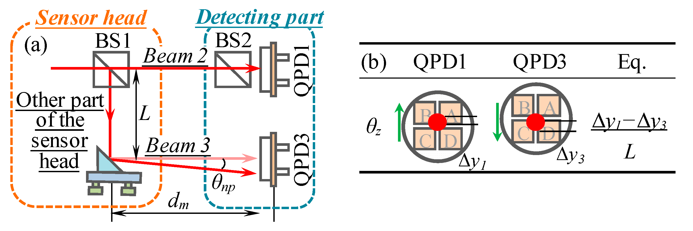
L between beam 2 and beam 3 was set to be 120 mm. Two high precision QPDs (QPD1 and QPD3, QP50-6-TO8, First Sensor, Germany) with an active area of 11.78 mm per element and a measurement resolution of 0.1 μm were chosen as the detectors of the straightness errors (
δx and
δy) and roll error (
θz). Therefore, the theoretical resolution for
δx,
δy, and
θz were evaluated to be 0.1 μm, 0.1 μm, and 0.17 arcsec, respectively. Two high precision QPDs (QPD2 and QPD4, QP5.8-6-TO5, First Sensor, Germany) with 4 × 1.44 mm
2 active area and a measurement resolution of 0.05 μm were applied as the detectors of pitch and yaw errors (
θx and
θy) and the beam drifted angular errors (
αx and
αy). The focal length of FL used in ACs (AC1 and AC2) is 20 mm, the theoretical resolution for
θx,
θy and
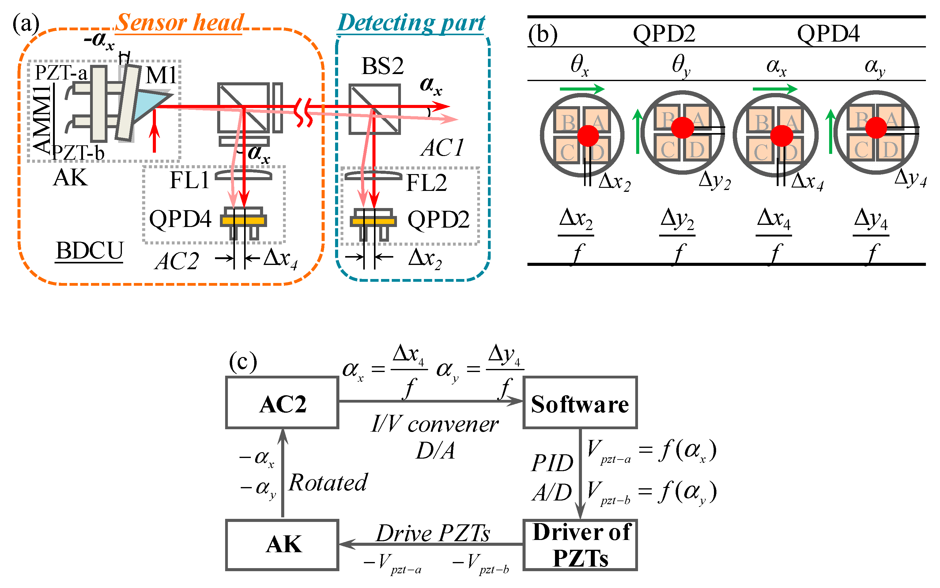
αx, αy are, thus, evaluated to be 0.25 arcsec. Two PZTs (AL1.65 × 1.65 × 5D-4F, NEC TOKIN Electronic, Sendai Janpan), an angle mirror mount (AMM1, GCM080205M, DHT Co., Beijing, China) and a right-angle mirror (M1, Foctek, Fujian, China) were used to construct the AK shown in
Figure 3a.
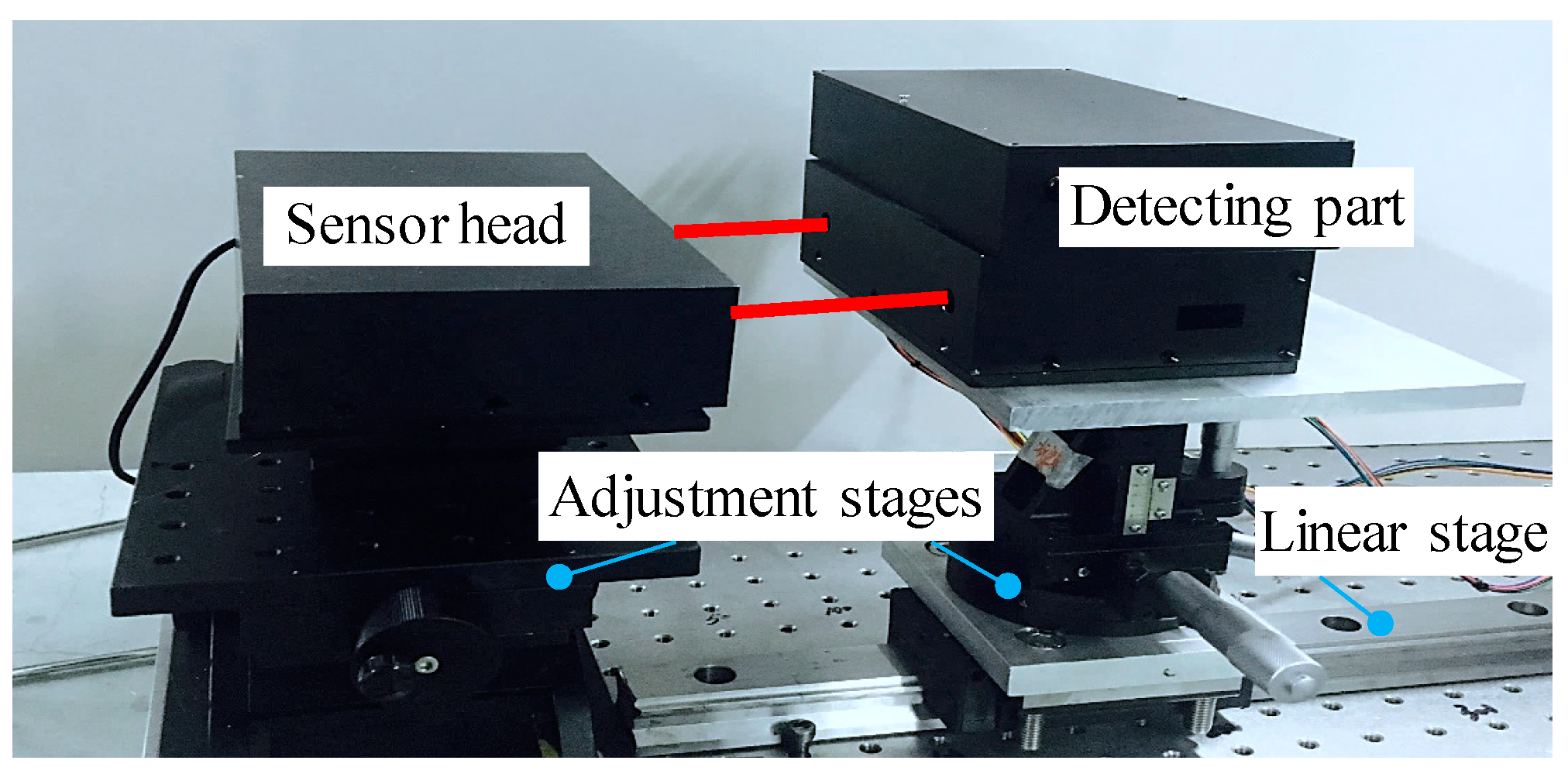
Figure 5 shows the photo of the prototype LMS supported by adjustment stages which are mounted on a linear stage more than 1.2 m long. The LMS consists of a sensor head and a detecting part. Different from most of other five-DOF or six-DOF measurement systems that reflect the light from the moving part to the sensor head, this developed LMS directly mounts the detecting sensors for five-DOF error motions on the moving stage. The main reason is to reduce the laser path distance so as to reduce the errors caused by the laser beam. In this LMS, a wireless transmission kit is used in the electronic unit to avoid errors caused by the push and pull of the cable. Such a prototype LMS possesses innovative features of compact, portable, easy installation, wireless, and low-cost. It is suitable for on-machine measurement.
3.1. Stability of the LMS
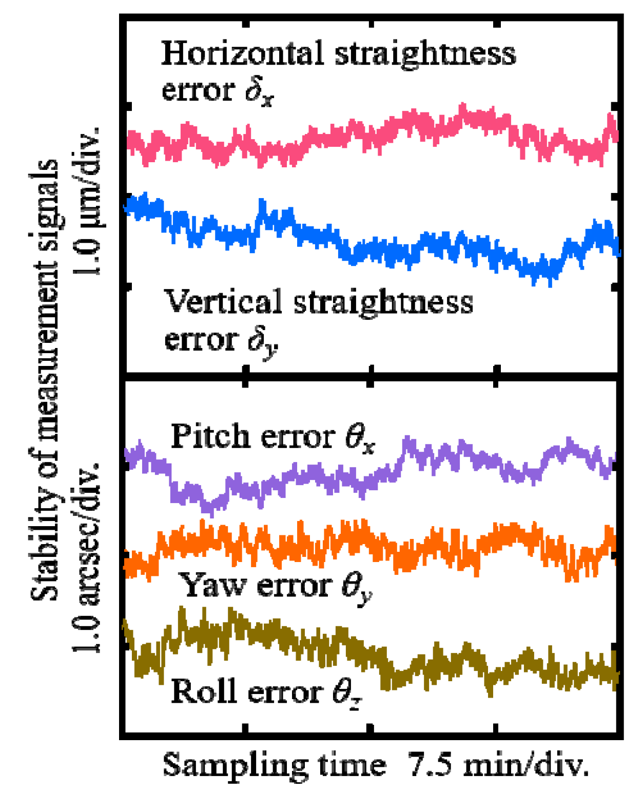
The stability of the LMS significantly influences the measurement accuracy of the error motions. The distance between the sensor head and the detecting part was first set to be 1.0 m for testing the stability. The sampling time and sampling frequency were set to be 30 min and 100 Hz, respectively. A moving average filter and a Butterworth filter were applied to reduce the noise levels of the measurement signals.
Figure 6 shows the stability of the measurement signals for five-DOF error motions when the BDCU was worked. The beam drifted angular errors can be controlled within ±0.01 arcsec using the BDCU although the figures are omitted for the sake of clarity. The stability of the measurement signals for
δx,
δy,
θx,
θy, and
θz was evaluated to be 0.7 μm, 0.8 μm, 0.8 arcsec, 0.5 arcsec, and 0.8 arcsec, respectively, in a non-environmental controlled open laboratory. It was verified that the stability of the LMS was satisfied for measuring the error motions of the linear stage.
3.2. Calibration Tests of the LMS
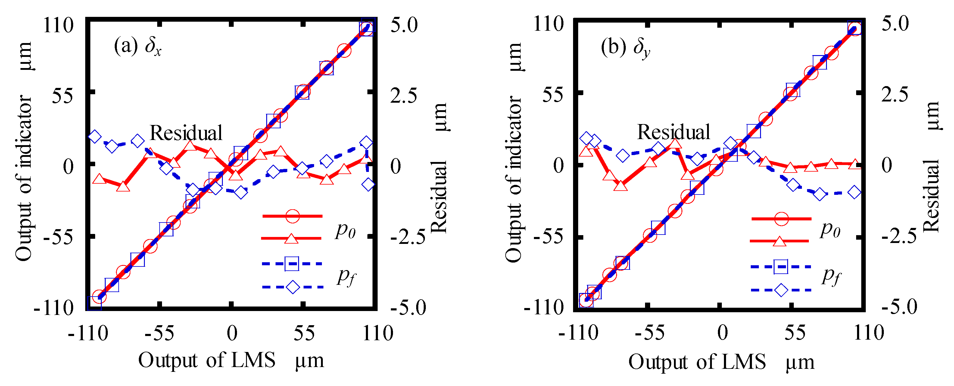
The measurement accuracy of the designed LMS was calibrated by a commercial measurement instrument in advance. The first (p0) and final (pf) measurement positions were set to be 0 mm and 1.08 mm, respectively.
Firstly, using an
XY manual linear stage, on which the detecting part was mounted, the motions were simultaneously detected by a commercial digital indicator (P12D HR, Sylvac, Switzerland), which has a resolution of 0.01 μm and a measurement accuracy of 0.22 μm. Since the commercial digital indicator could only detect one-directional displacement, the position of the digital indicator should be changed for the calibration along a different direction. The
X- and
Y-directional calibration results at
p0 and
pf are shown in
Figure 7a,b, respectively. As seen in
Figure 7a, the maximum residual of
δx were evaluated to ±0.7 μm and ±0.9 μm in the calibration range of ±100 μm at
p0 and
pf, respectively. Similar calibration results of
δy were also obtained, as shown in
Figure 7b.
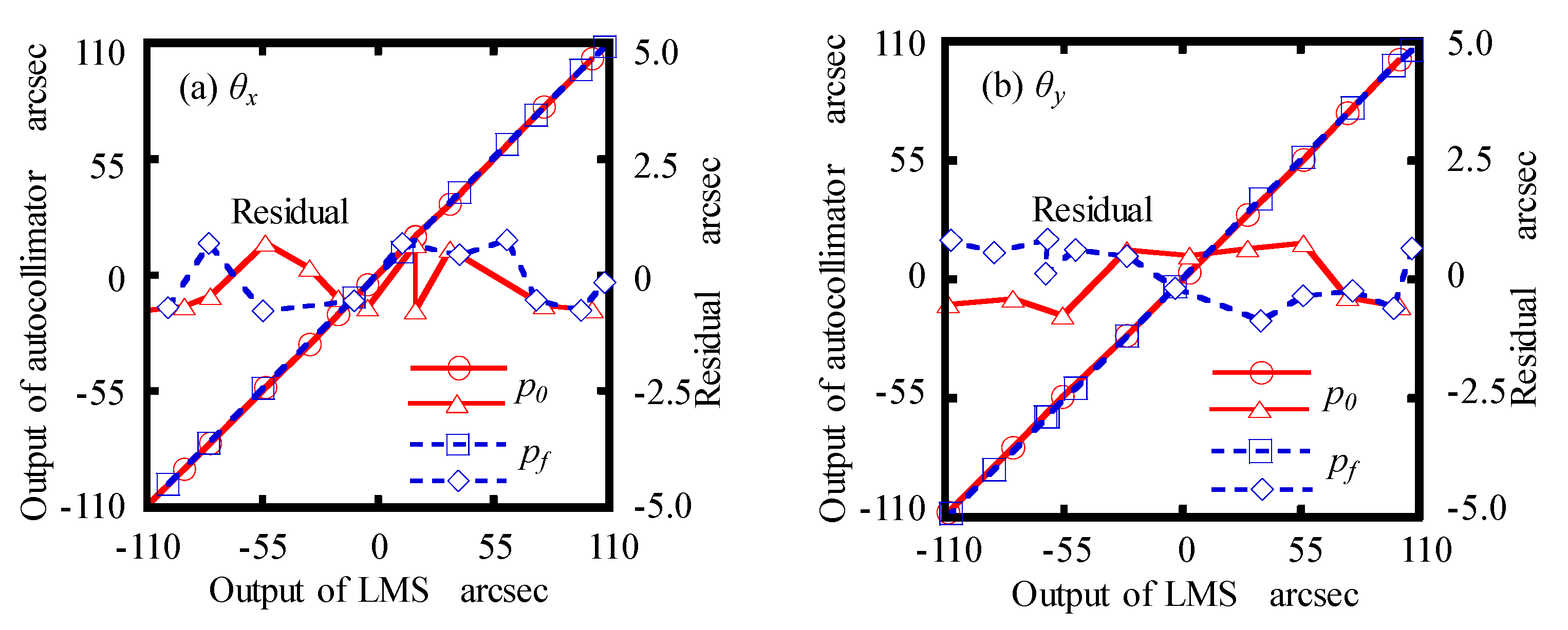
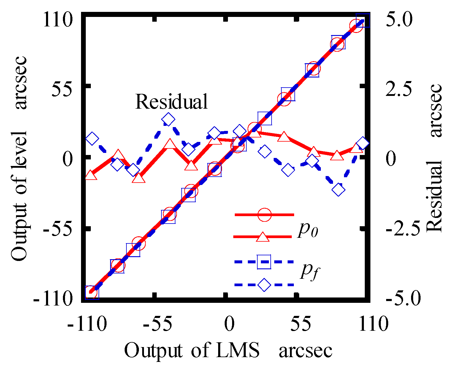
Then, a commercial autocollimator (5000U3050, AutoMat, China), with a measurement accuracy of 0.2 arcsec and repeatability of 0.05 arcsec, was used to calibrate the angular errors measurement performance of the LMS. The detecting part and the reflector of the autocollimator were mounted on a manual rotary stage and a manual goniometer stage. The angular displacements of the stages could be simultaneously measured by the LMS and autocollimator.
Figure 8a shows the maximum residuals of
θx, which were found to be between ±0.6 arcsec and ±0.7 arcsec in the calibration range of ±100 arcsec at
p0 and
pf, respectively. The maximum residuals of
θy, which were estimated to be ±0.7 arcsec at
p0 and ±0.8 arcsec at
pf within the calibration range of ±100 arcsec, respectively, are shown in
Figure 8b.
Finally, a high precision commercial electronic level (WL/AL11, Qianshao, China), which has a measurement accuracy of 0.2 arcsec, was employed to calibrate the roll error measurement performance of the designed LMS. The detecting part and the electronic level were installed on a manual goniometer stage, which can be rotated about
Z-axis. The maximum residual of each calibration, shown in
Figure 9, was within ±0.7 arcsec and ±1.1 arcsec at
p0 and
pf in the calibration range of ± 100 arcsec.
Therefore, it was verified from the calibration results that the designed LMS can be acceptable for sub-micrometer precision straightness error measurement within ±100 μm and sub-arcsecond precision angular error measurement within ±100 arcsec.
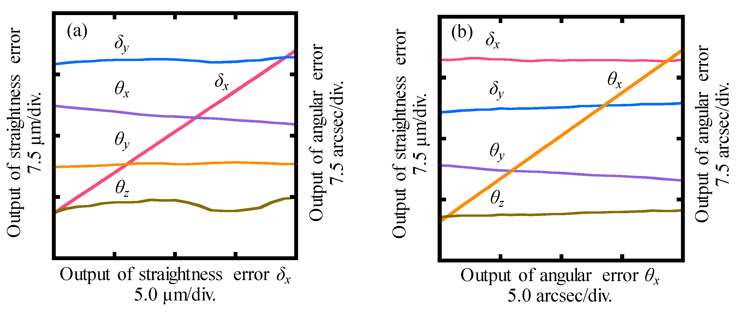
3.3. Crosstalk Error Analysis of the LMS
The last test was carried out to investigate the crosstalk errors between the outputs of the LMS when the detecting part was moved along the
X- and
Y-directions, and rotated about the
X-,
Y- and
Z-directions, respectively. In order to avoid the influence of the crosstalk errors of the manual stages, a short movement range of about ±10 μm was applied to linear error and ±10 arcsec was applied to rotational error.
Figure 10a shows the outputs of the LMS when the detecting part was moved along the
X-direction. Variations of
δy,
θx,
θy, and
θz, which were approximately 0.8 μm, 2.2 arcsec, 0.5 arcsec and 1.8 arcsec, respectively, indicated the crosstalk errors of the LMS with respect to the
X-directional motion of 20.0 μm. Similarly, variations were detected in the output of
δx,
δy,
θy, and
θz when an angular displacement
θx of 20.0 arcsec was applied to the detecting part with respect to the sensor head, as shown in
Figure 10b. For the sake of clarity, the crosstalk errors of the LMS are summarized in
Table 1. The crosstalk errors were quite large compared with the theoretical measurement resolutions of the LMS.
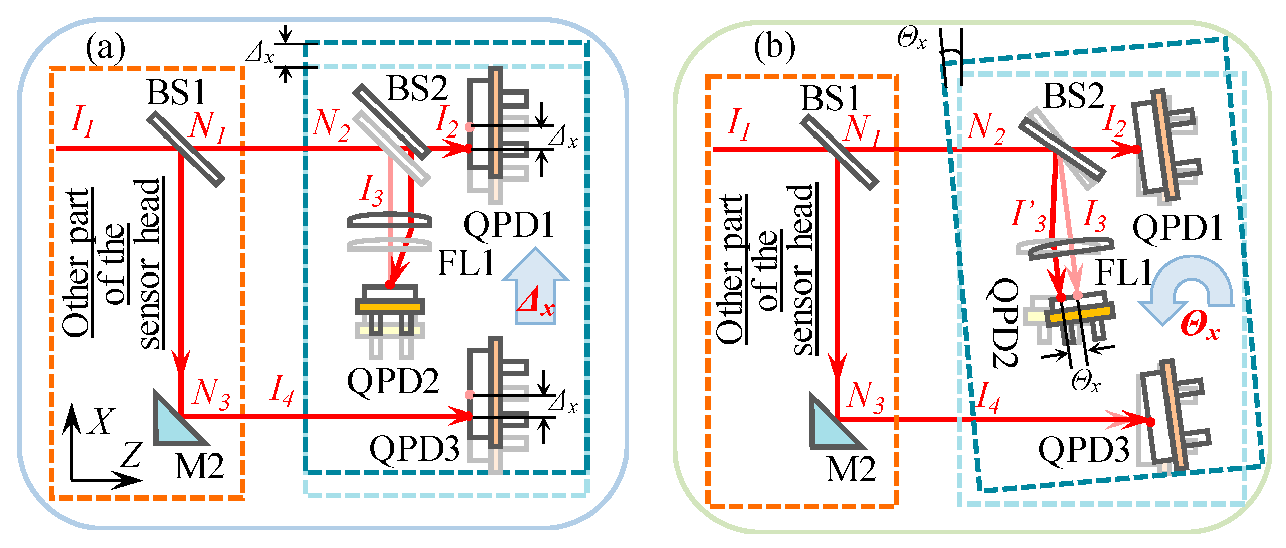
Confirmation of the reasons for generating the crosstalk errors was firstly carried out by analyzing the optical design of the LMS using the ray-tracing method, as shown in
Figure 11. The laser beam
I1 travels in the direction of the Z-axis with a direction vector of
. The direction vector of reflection planes of BS1, BS2, and M2 can be expressed by:
The transformation matrix of the reflection planes of the BS1, BS2, and M2 can be obtained as follows:
Thus, the direction vectors
I2,
I3, and
I4 can be expressed as
When the detecting part of the LMS was applied to a linear displacement of Δ
x, shown in
Figure 11a, the direction vectors
I2,
I3, and
I4 did not vary. Therefore, it was verified that the output of linear errors will not affect that of the angular errors in the designed LMS.
An angular displacement of Θ
x was, then, applied to the detecting part, as shown in
Figure 11b. The direction vector
N3 of the BS2’s reflection plane was influenced by the angular displacement.
N3 will be varied to be
Thus, the effect of Θ
x on
I3 can be evaluated to be
Θx can be detected by AC1 based on Equation (3). However, the direction vectors I2 and I4 were not changed by the angular displacement, which meant that the outputs of angular errors would also not affect those of the linear errors in the designed LMS.
The main error sources that caused the crosstalk errors were deemed the systematic errors, including the manufacture errors and installation errors of the optical components. In order to eliminate the influence of the systematic errors on the crosstalk errors, a compensation model, referred to as the modified measurement model, was proposed as follows,
where,
Mn (
M =
A,
B,
C,
D and
E,
n = 1, 2, 3, 4, and 5) are the coefficients of the crosstalk errors.
δx-L,
δy-L,
θx-L,
θy-L and
θz-L represent the actual five-DOF error motions of the linear stage, respectively.
δ′x,
δ′y,
θ′x,
θ′y and
θ′z are the outputs of the LMS with the compensations of the detector sensitivity and dual-beam non-parallelism based on Equations (2) and (6). According to experimental results shown in
Figure 10, the error coefficients of the designed LMS can be estimated to be
Table 2 shows the crosstalk errors of the LMS after compensation based on Equations (15) and (16). It can be seen that the crosstalk errors were significantly removed from the outputs of the LMS. The residual errors shown in
Table 2 were dominated by the influence of the stability of the designed measurement system and the electronic noise of the photoelectric processing circuit.
4. Measurement of Error Motions of a Linear Stage
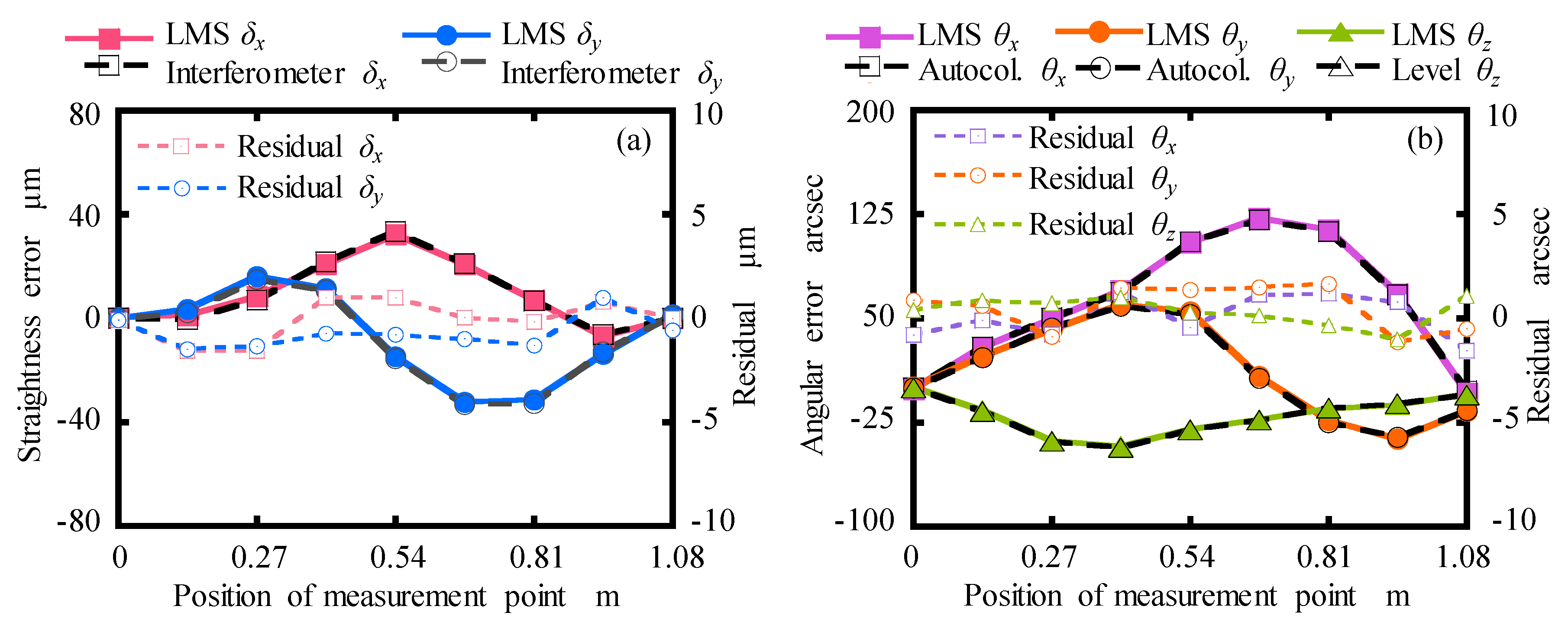
The performance investigations of the designed LMS for measuring the error motions of a linear stage were carried out. The travel distance of the linear stage is 1.2 m. The moving stage of the linear stage was manually moved approximately 120 mm in steps to 1.08 m. It should be noted that the crosstalk errors in the following experimental results were compensated by using the modified measurement model.
The measurement experiments of the straightness errors, pitch and yaw errors and roll error were conducted by the comparison between the constructed LMS and high-precision commercial measurement instruments, including a laser interferometer (Agilent 5530, Keysight Technologies, Santa Clara, CA, USA) for measuring the straightness errors, the autocollimator for measuring the pitch and yaw errors, and the electrical level for measuring the roll error. The measured results are shown in
Figure 12. It can be seen that the measured results by using the designed LMS were in a good agreement with the detected results of the commercial instruments. It has also been confirmed that the error motions measurements have good repeatability by five measurements although the figures are omitted for the sake of brevity. The maximum residuals for five measurements were calculated to be within ±1.5 μm, ±1.5 μm, ±1.8 arcsec, ±1.7 arcsec and ±1.5 arcsec corresponding to
δx,
δy,
θy,
θy, and
θz, respectively.
The experimental results show good measurement accuracy and repeatability of the designed LMS. It was confirmed that the designed LMS and modified measurement model have the potential to simultaneously measure the five-DOF error motions of a linear stage in a non-environmental controlled open laboratory.
5. Conclusions
This paper presented a newly designed laser measurement system (LMS), consisting of a sensor head and a detecting part, for simultaneously measuring five-DOF error motions (horizontal and vertical straightness errors, pitch error, yaw error and roll error) of linear stages. The measurement principles were described. The measurement errors of the LMS, which were induced by the variation of detector sensitivity, the laser beam drifted angular errors, the two-laser beam non-parallelism and the crosstalk errors, have been analyzed in detail, from which the measurement model was modified. A prototype of the LMS was constructed, in which a low-cost laser diode was used as the laser source. The effectiveness of the designed LMS and the modified measurement model were verified by a series of calibration and comparison experiments. Based on the comparison experiments of measuring the error motion of a linear stage, the residuals of the straightness errors, pitch error, yaw error and roll error were less than ±1.5 μm, ±1.8 arcsec, ±1.7 arcsec and ±1.5 arcsec compared with the laser interferometer, autocollimator and electrical level. The improvement of measurement accuracy and the uncertainty analysis will be carried out in the future research.


