The AMERIGO Lander and the Automatic Benthic Chamber (CBA): Two New Instruments to Measure Benthic Fluxes of Dissolved Chemical Species †

 ,
,  ,
,
Abstract
:
1. Introduction
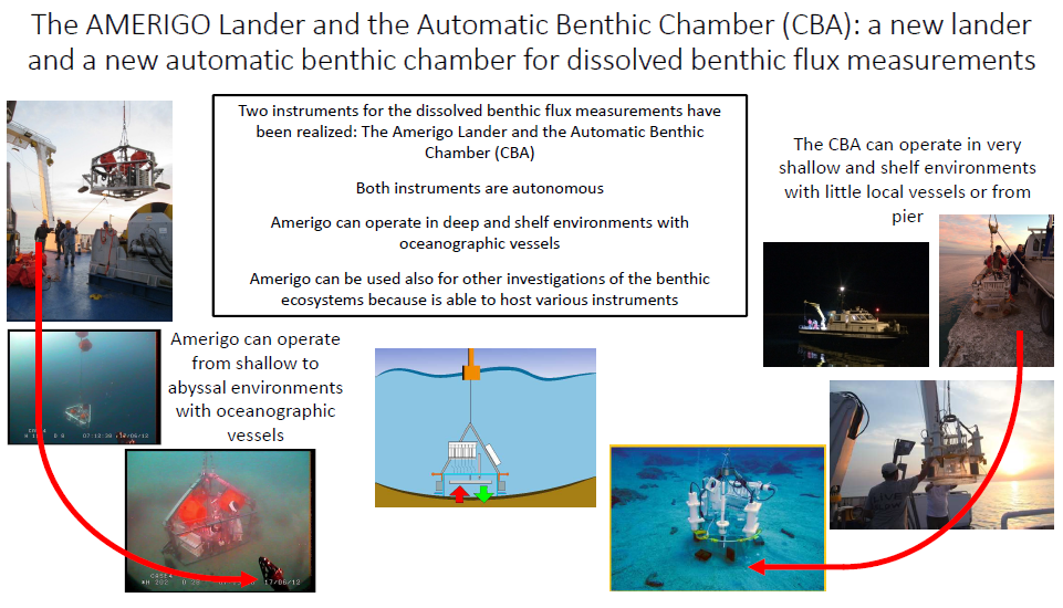
2. Amerigo Lander and Automatic Benthic Chamber: Technical Specifications and Equipment
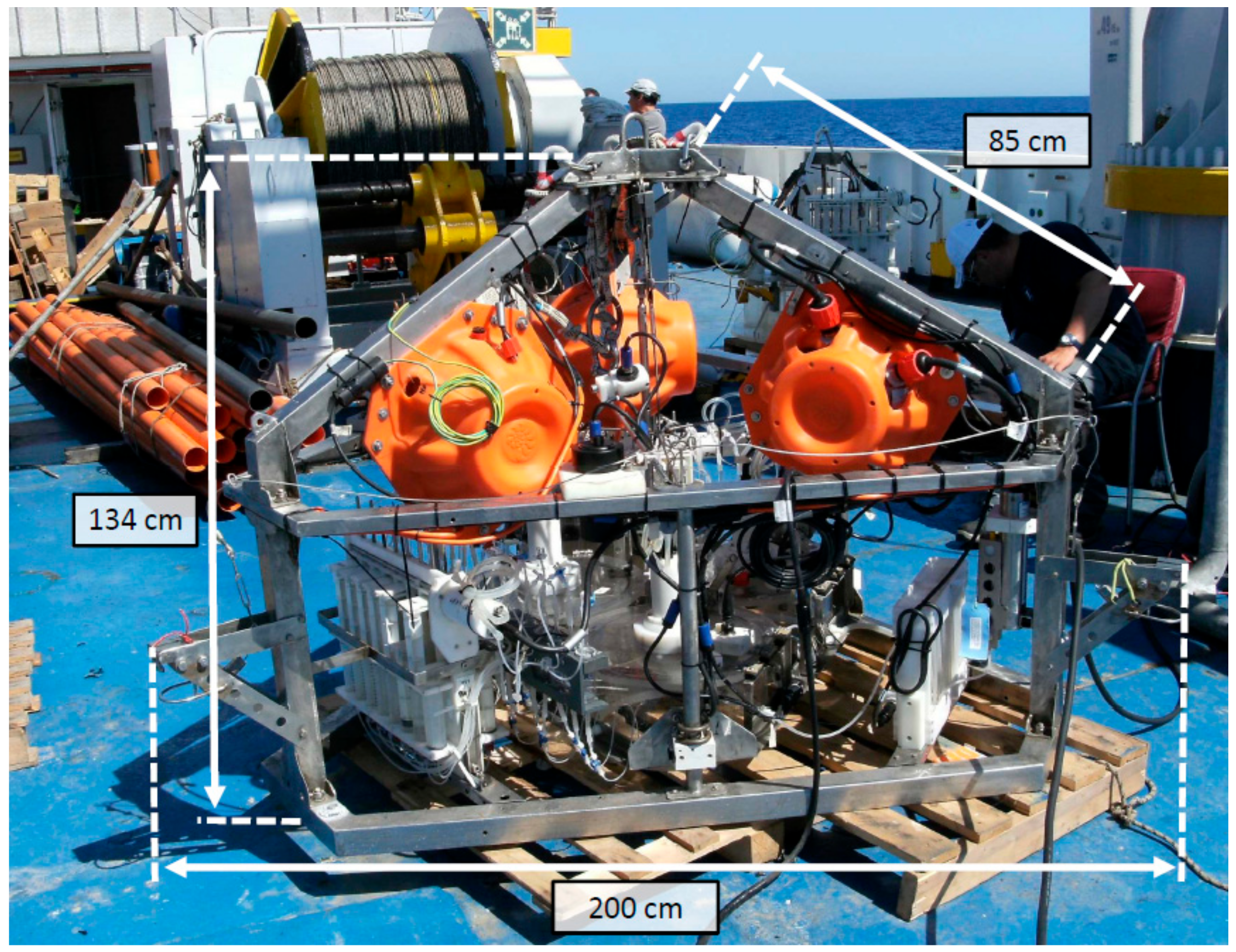
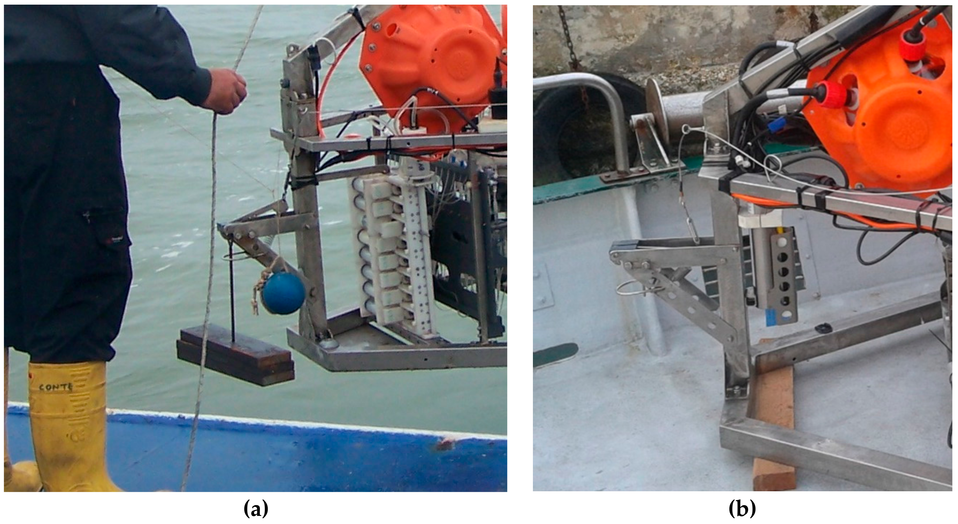
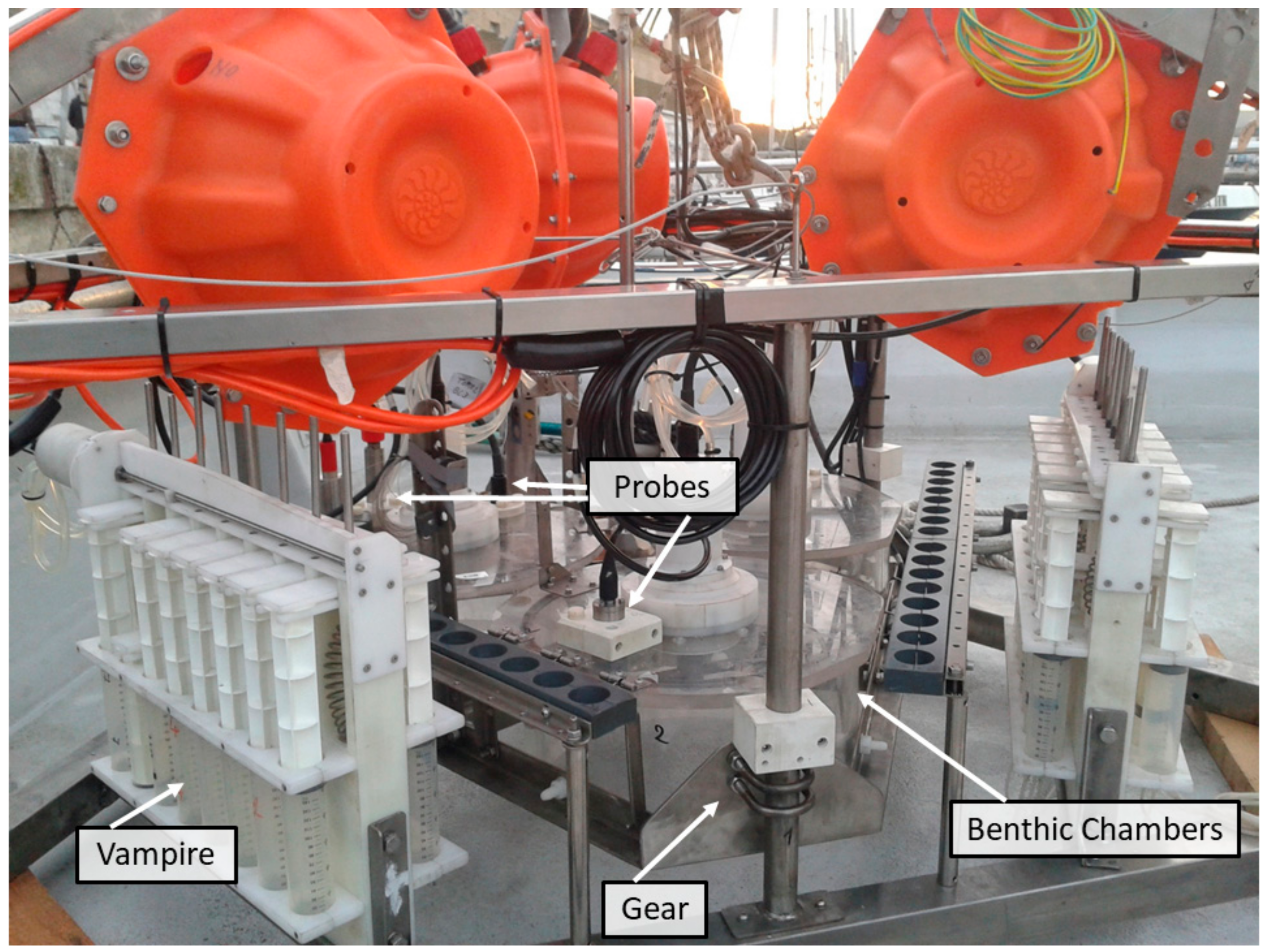
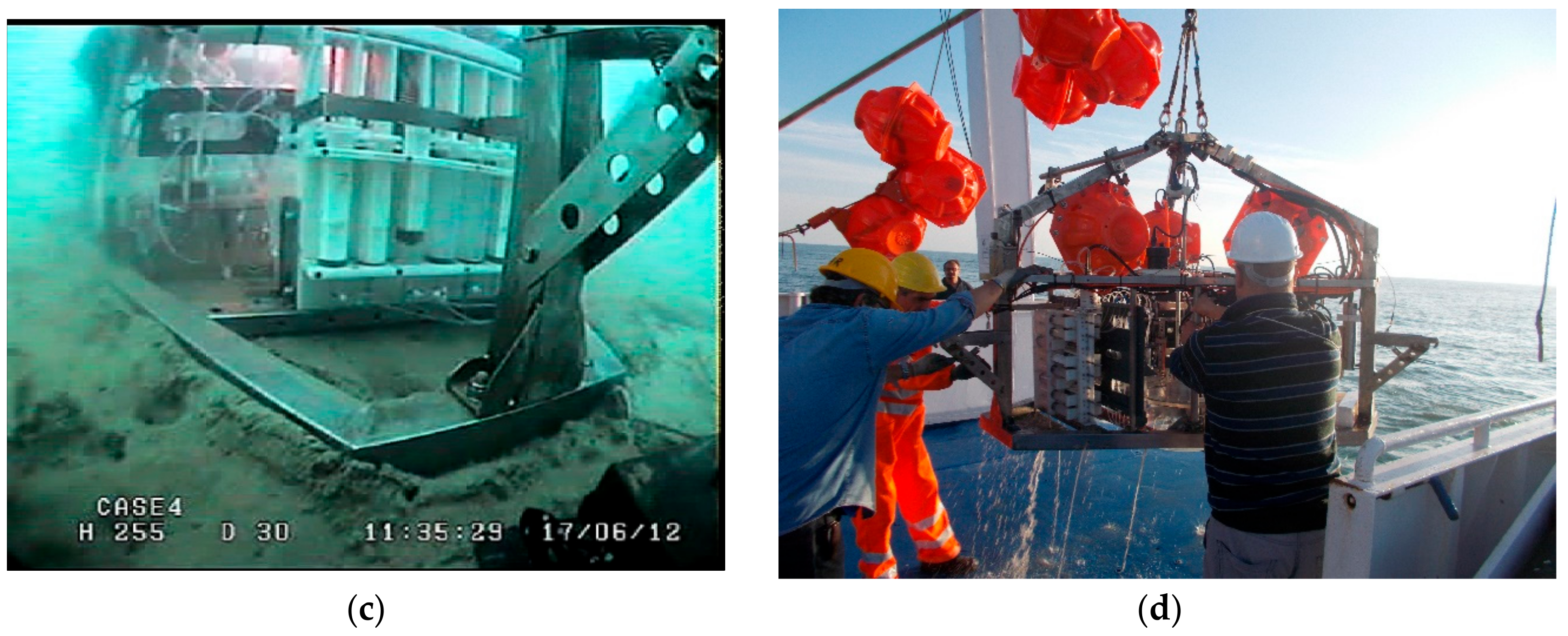
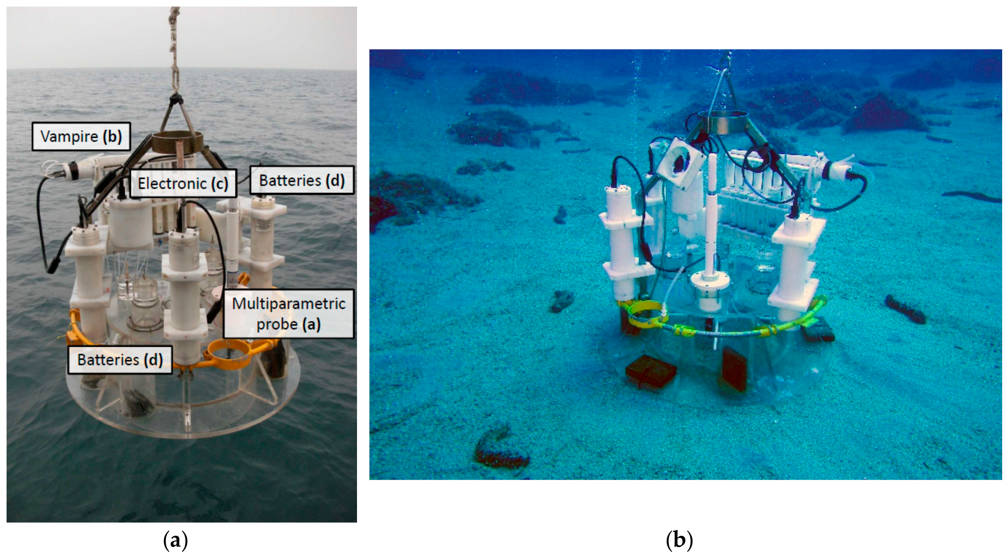
2.1. The Amerigo Lander
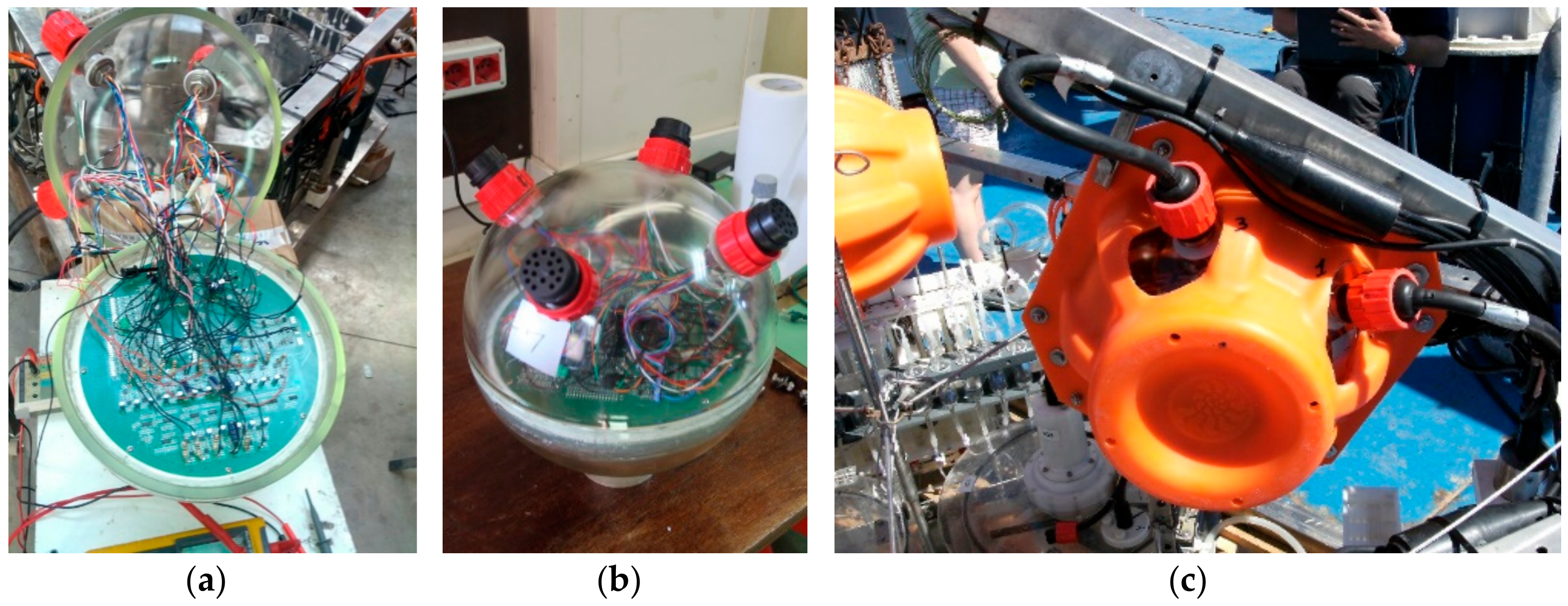
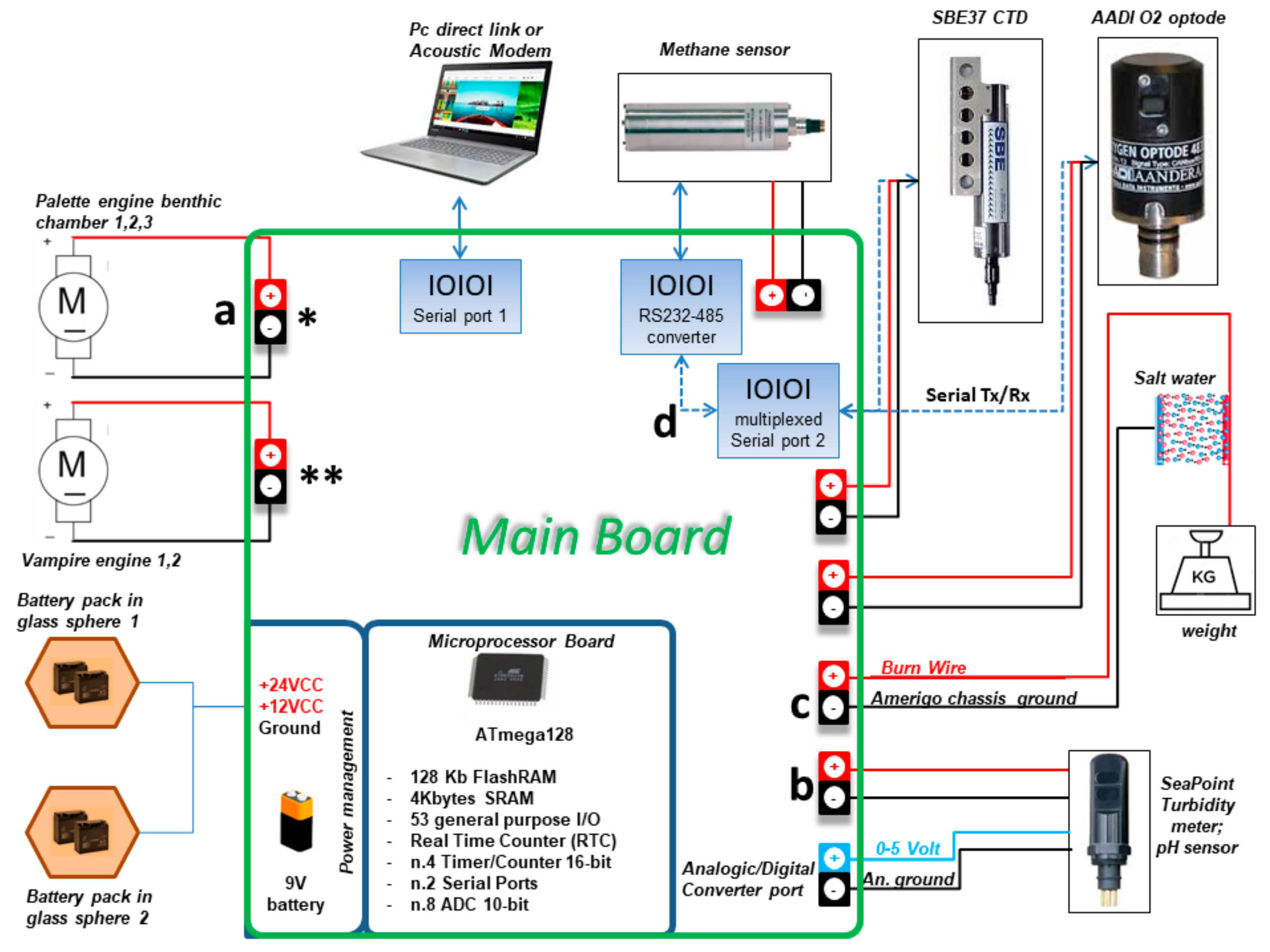
2.2. Electronics and Power Supply
2.3. Burn Wire Device
2.4. Current Configuration of the Amerigo Lander
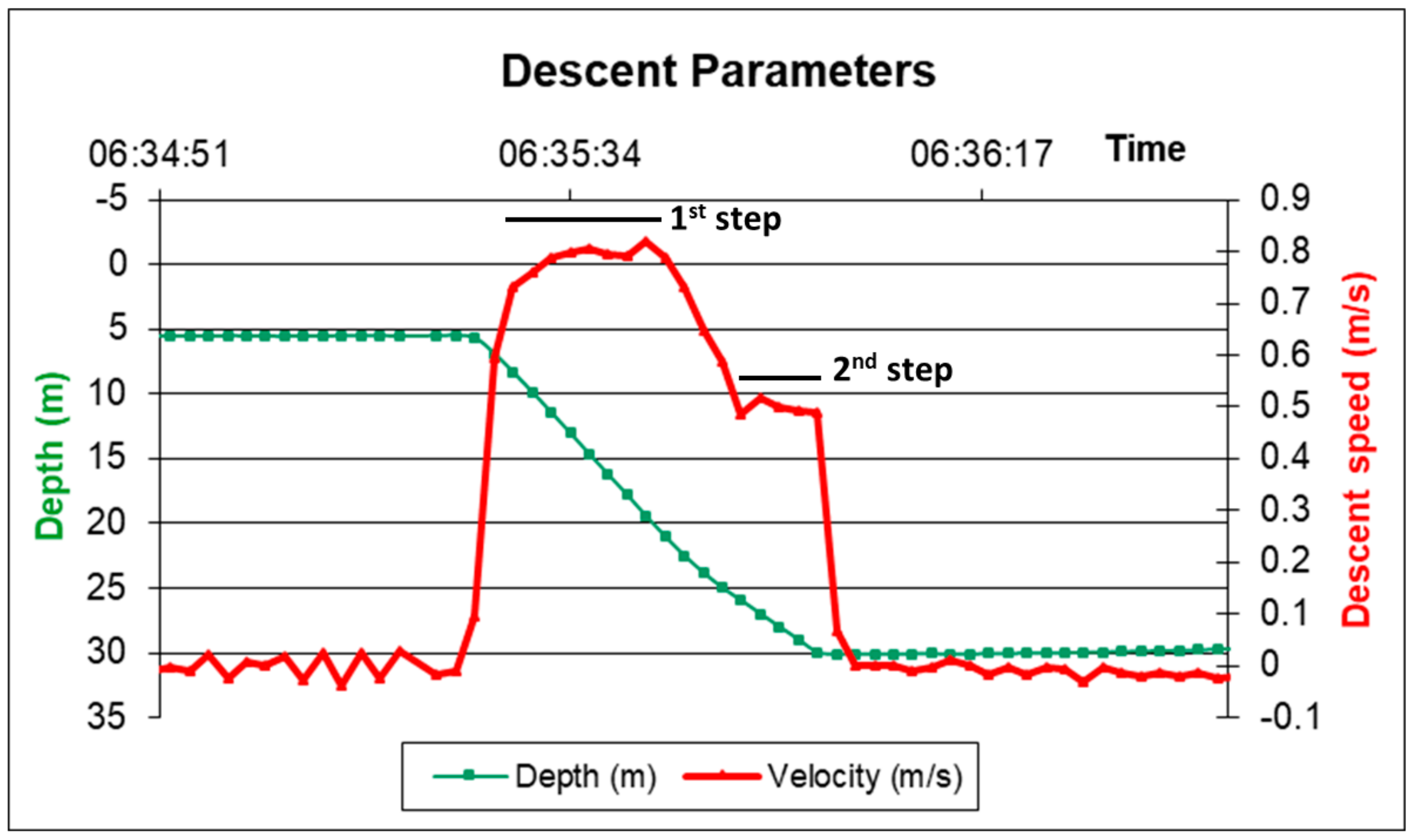
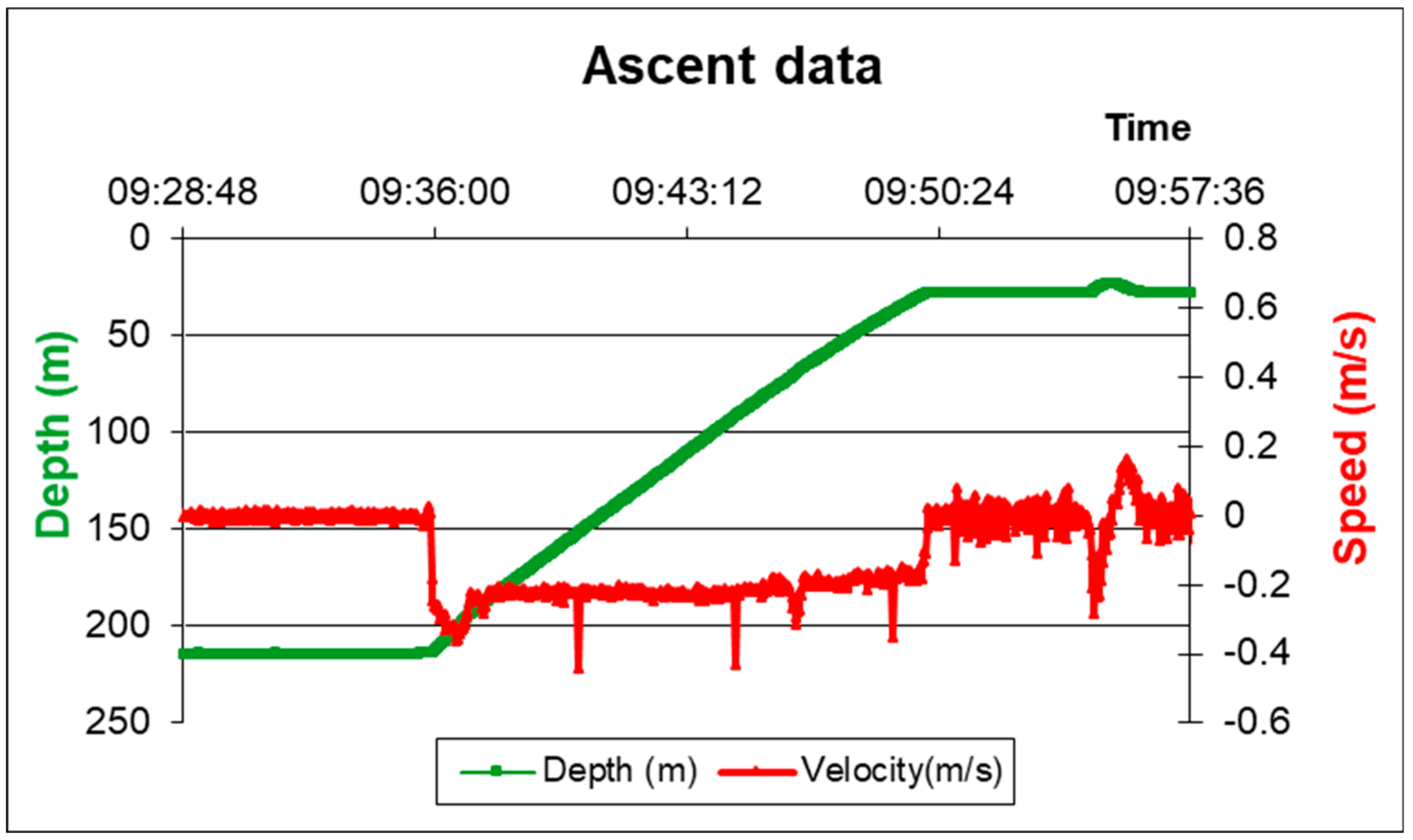
2.5. Typical Mission of the Amerigo Lander
- 1)
- After the on board programming and checks, such as control of the mooring line and testing of motors, sensors, communication, and security equipment, the lander is immersed into the sea, where it is held at a depth of 5 m, until activation of a dedicated burn wire mechanism releases a small buoy that confirms the functioning of the whole electronic system;
- 2)
- Following the buoy check, the lander is released for its free fall to the bottom;
- 3)
- After the lander has reached the seabed, a short interval is envisaged to allow the settling of the sediment resuspension, due to the impact of the tripod on the bottom, to settle;
- 4)
- Activation of a burn wire mechanism releases the chamber chassis, enabling its settling on the bottom and penetration into sediment for the first 5 cm; all the sensors in the chamber (oxygen, methane, turbidity) and CTD are sampled; the chambers are still open;
- 5)
- After another interval, to allow settling of the sediment resuspension due to the impact of the chamber on the bottom and to enable sensor readings, activation of another burn wire releases the benthic chamber lids;
- 6)
- Activation of the stirring paddles allows for mixing the seawater in the chambers;
- 7)
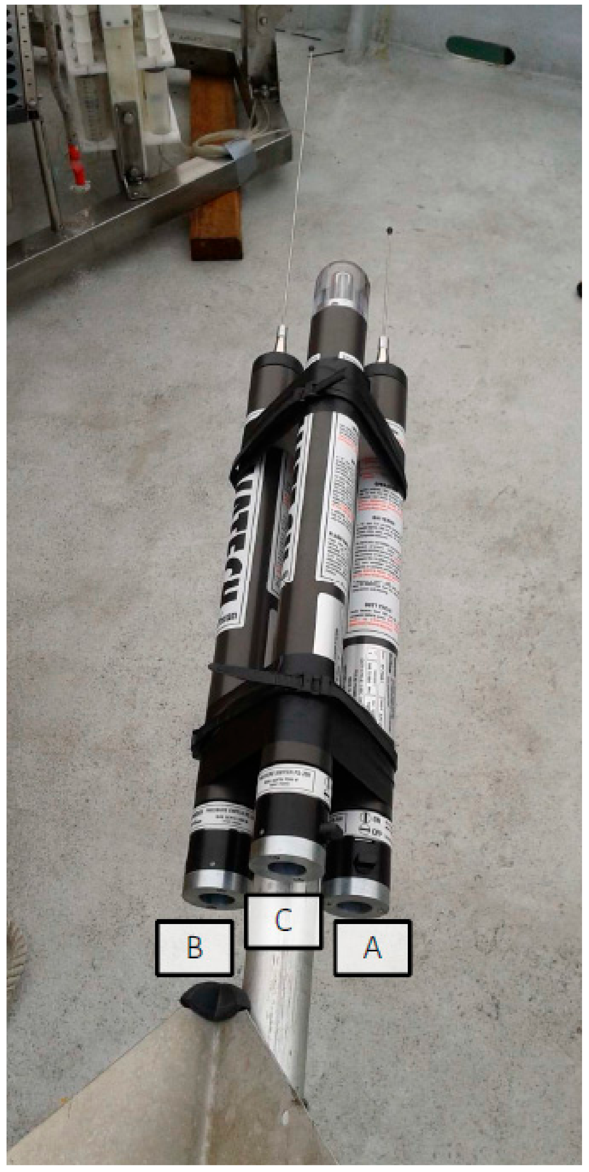
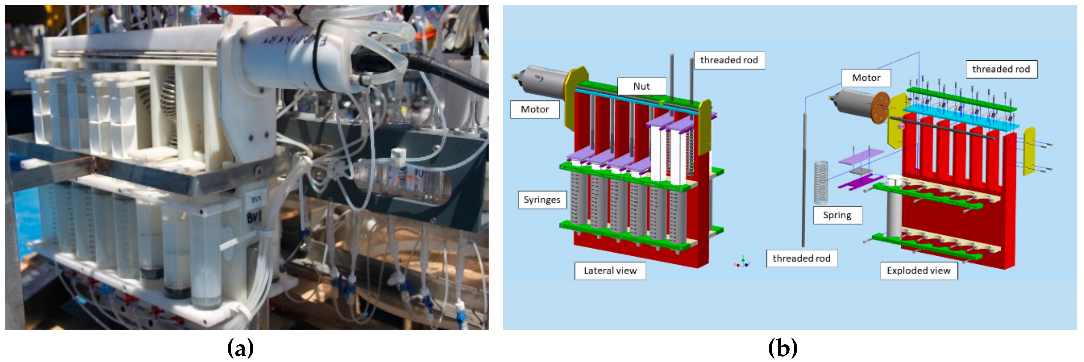
- The 8 pairs of syringes of the 2 VAMPIRES are activated by user-programmable times;
- 8)
- Finally, the ballast weights are released by the last burn wire and the lander floats back to the surface by virtue of its positive buoyancy.
2.6. Other Possible Configurations of the Amerigo Lander
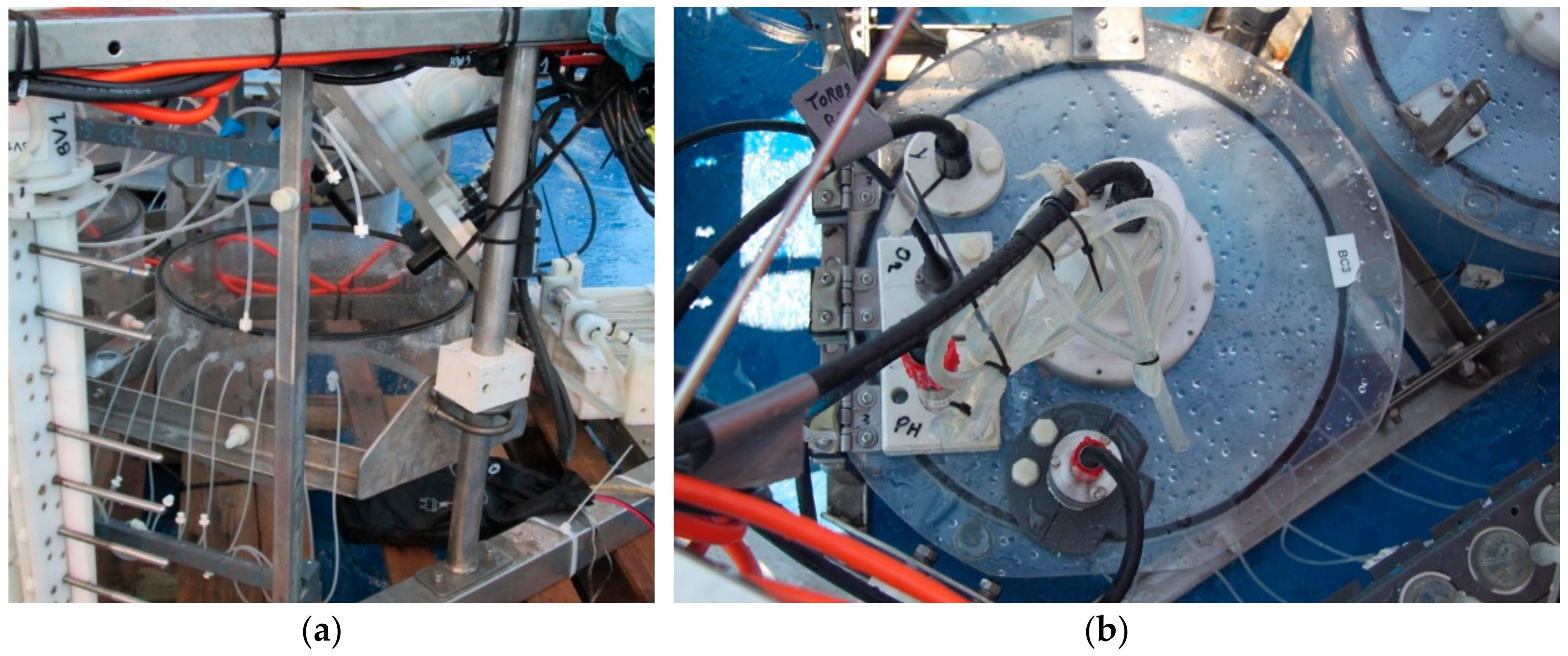
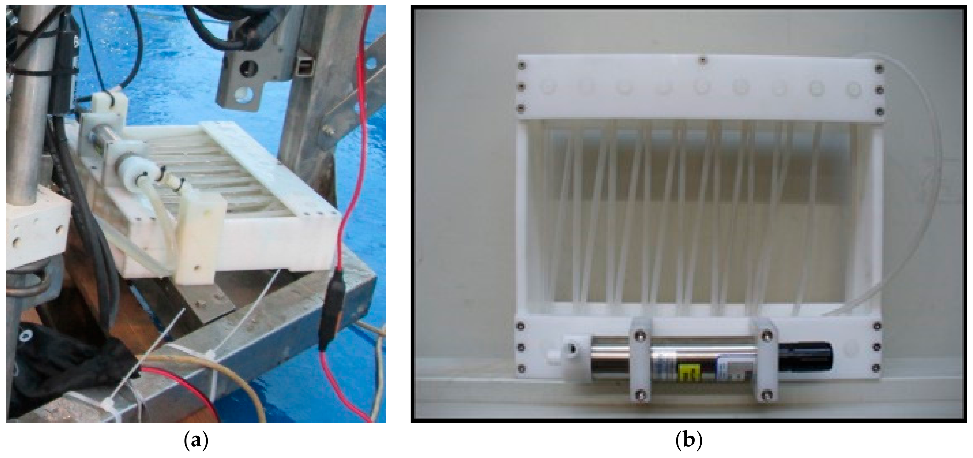
2.7. The Automatic Benthic Chamber
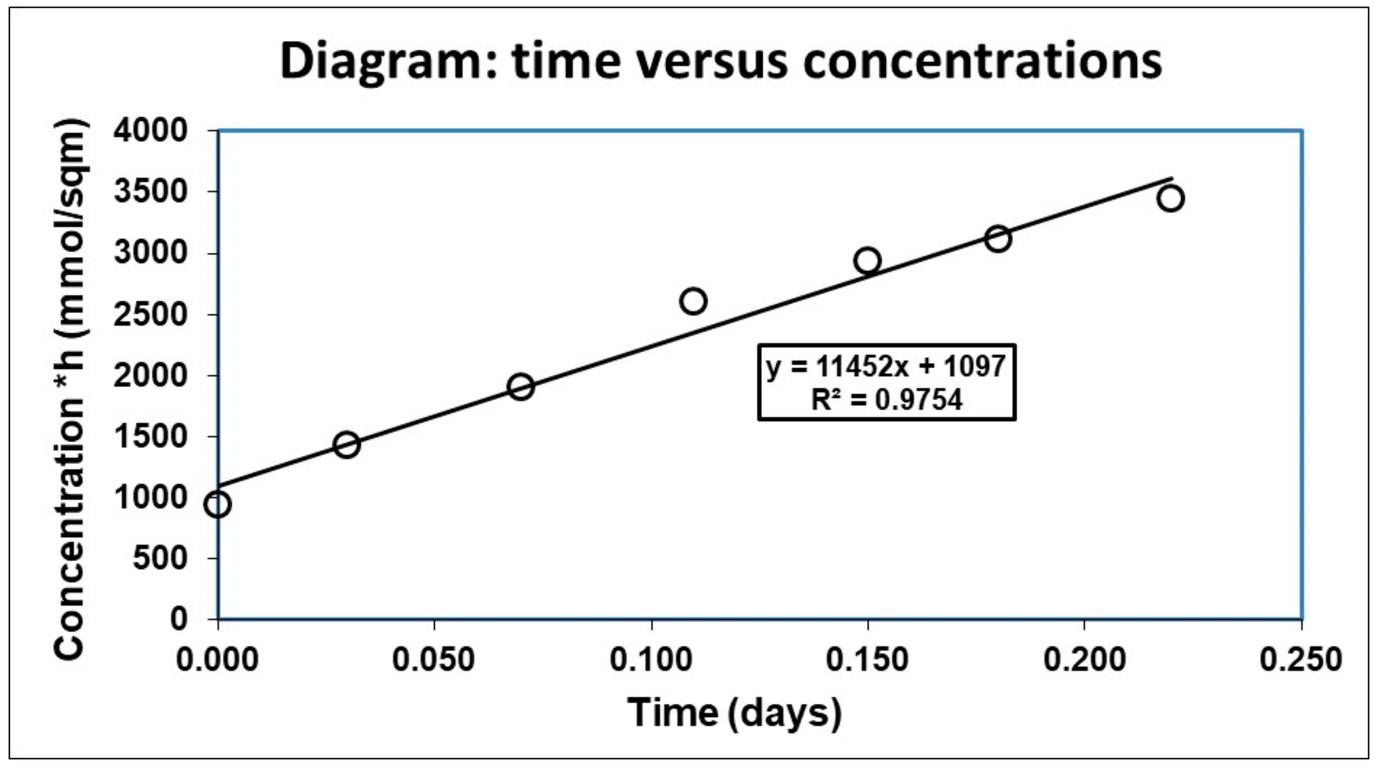
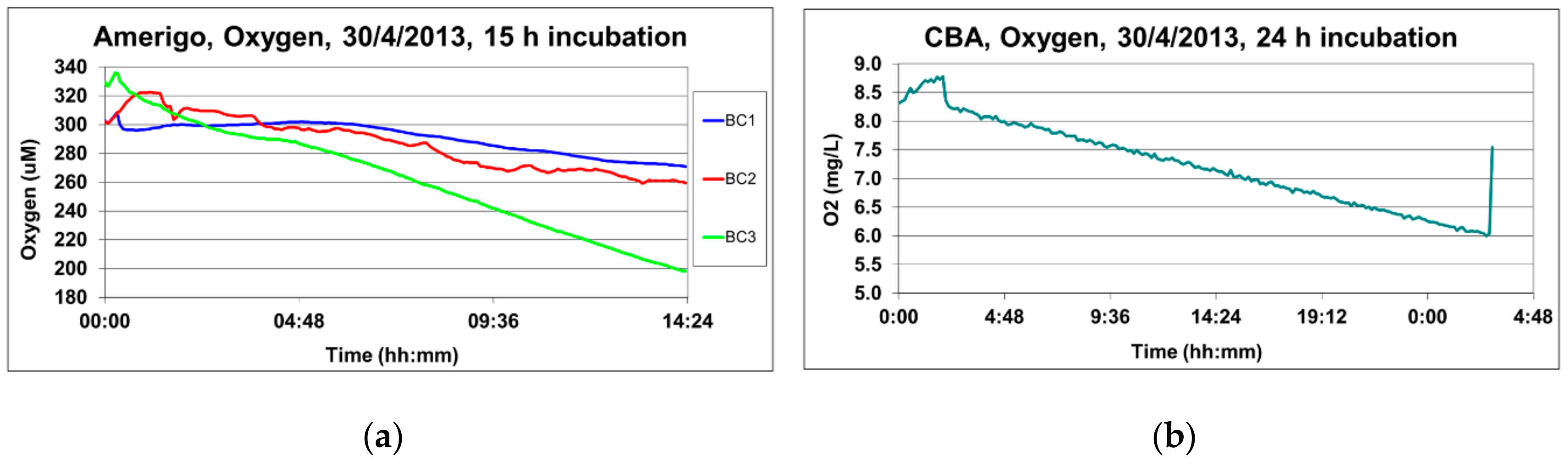
3. Benthic Flux Calculation
4. Discussion
5. Conclusions
Author Contributions
Funding
Acknowledgments
Conflicts of Interest
Appendix A


| Type | Description |
|---|---|
| Microprocessor | ATmega128 |
| RAM flash 128 Kb | |
| RAM 4Kb | |
| e2prom 4Kb | |
| Internal clock | |
| n. 3 timer 16 bit | |
| n. 8 ADC channels 10 bit | |
| n. 2 TTL serial ports | |
| External circuit | serial flash RAM 4Mb |
| n. 2 RS232 serial ports | |
| n. 3 RS485 ports | |
| n. 8 analogic inputs n. 2 digital inputsn. 20 on/off ports (H-bridge with electronic shunt) |
| Name | Type | Description |
|---|---|---|
| OUT 1 | ON/OFF | Power terminals for CTD sensor |
| OUT 2 | ON/OFF | Power terminals for O2 sensor number 1, chamber n.1 |
| OUT 2 | ON/OFF | Power terminals for O2 sensor number 2, chamber n.2 |
| OUT 4 | ON/OFF | Power terminals for O2 sensor number 3, chamber n.3 |
| OUT 5 | ON/OFF | Power terminals for CH4 sensor number 1, chamber n.1 |
| OUT 6 | ON/OFF | Power terminals for CH4 sensor number 2, chamber n.2 |
| OUT 7 | ON/OFF | Power terminals for CH4 sensor number 3, chamber n.3 |
| OUT 8 | ON/OFF | Power terminals for analogic sensors (n.2 turbidity and n.1pH) |
| OUT 9 | ON/OFF | Power terminals - Engine palette chamber n.1 (mixing water) |
| OUT 10 | ON/OFF | Power terminals - Engine palette chamber n.2 (mixing water) |
| OUT 11 | ON/OFF | Power terminals -Engine palette chamber n.3 (mixing water) |
| OUT 12 | ON/OFF | Engine VAMPIRONE number 1 |
| OUT 13 | ON/OFF | Engine VAMPIRONE number 2 |
| OUT 14 | ON/OFF | Burn wire n.1 Buoy electronic check |
| OUT 15 | ON/OFF | Burn wire n.2 Benthic chamber release |
| OUT 16 | ON/OFF | Burn wire n.3 Benthic chamber cover release |
| OUT 17 | ON/OFF | Burn wire n.4 Benthic chamber cover release |
| OUT 18 | ON/OFF | Burn wire n.5 weights release |
| OUT 19 | ON/OFF | Power terminals 24 Volts for microprofiler |
| OUT 20 | ON/OFF | OxyStat pump |
| RS232 1 | RS232 | Main serial port - PC communication |
| RS232 2-1 | RS232 | CTD |
| RS232 2-2 | RS232 | serial communication with O2 sensor n. 1, chamber n.1 |
| RS232 2-3 | RS232 | serial communication with O2 sensor n. 2, chamber n.2 |
| RS232 2-4 | RS232 | serial communication with O2 sensor n. 3, chamber n.3 |
| RS232 2-5 | RS232 | serial communication with pH sensor n. 1, chamber n.1 |
| RS232 2-6 | RS232 | serial communication with pH sensor n. 2, chamber n.2 |
| RS232 2-7 | RS232 | serial communication with pH sensor n. 3, chamber n.3 |
| RS485 1 | RS485 | serial communication with CH4 sensor n. 1, chamber n.1 |
| RS485 2 | RS485 | serial communication with CH4 sensor n. 2, chamber n.2 |
| RS485 3 | RS485 | serial communication with CH4 sensor n. 3, chamber n.3 |
| an 1 | analogical in | Analogical (0-5V) Turbidity sensor n. 1, chamber n.1 |
| an 2 | analogical in | Analogical (0-5V) Turbidity sensor n. 2, chamber n.2 |
| an 3 | analogical in | Analogical (0-5V) Turbidity sensor n. 3, chamber n.3 |
| an 4 | analogical in | NC-future purpose (pCO2) |
| an 5 | analogical in | NC-future purpose (Eh) |
| an 6 | analogical in | NC-future purpose (H2S) |
| an 7 | analogical in | NC-future purpose (other sensor) |
| an 8 | analogical in | NC-future purpose (other sensor) |
| DI 1 | digital IN | magnetic sensor (future purpose, VAMPIRONE position) |
| DI 2 | digital IN | magnetic sensor (future purpose, VAMPIRONE position) |
References
- Douvere, F. The importance of marine spatial planning in advancing ecosystem-based sea use management. Mar. Policy 2008, 32, 762–771. [Google Scholar] [CrossRef]
- Pérez-Albaladejo, E.; Rizzi, J.; Fernandes, D.; Lille-Langøy, R.; Goksøyr, A.; Oros, A.; Spagnoli, F.; Porte, C. Assessment of the environmental quality of coastal sediments by using a combination of in vitro bioassays. Mar. Pollut. Bull. 2016, 108, 53–61. [Google Scholar] [CrossRef] [PubMed]
- Catalano, G.; Azzaro, M.; Bastianini, M.; Bellucci, L.G.; Bernardi Aubry, F.; Bianchi, F.; Burca, M.; Cantoni, C.; Caruso, G.; Casotti, R.; et al. The carbon budget in the northern Adriatic Sea, a winter case study. J. Geophys. Res. Biogeosci. 2014, 119, 1399–1417. [Google Scholar] [CrossRef] [Green Version]
- Legendre, L. Marine Biogeochemical Cycles; John Wiley & Sons, Inc.: Hoboken, NJ, USA, 2014; pp. 145–187. [Google Scholar]
- Pörtner, H.-O.; Karl, D.M.; Boyd, P.W.; Cheung, W.W.L.; Lluch-Cota, S.E.; Nojiri, Y.; Schmidt, D.N.; Zavialov, P.O. Ocean systems. In Climate Change 2014: Impacts, Adaptation, and Vulnerability. Part A: Global and Sectoral Aspects. Contribution of Working Group II to the Fifth Assessment Report of the Intergovernmental Panel on Climate Change; Field, C.B., Barros, V.R., Dokken, D.J., Mach, K.J., Mastrandrea, M.D., Bilir, T.E., Chatterjee, M., Ebi, K.L., Estrada, Y.O., Genova, R.C., et al., Eds.; Cambridge University Press: Cambridge, UK, 2014; pp. 411–484. [Google Scholar]
- Gattuso, J.P.; Magnan, A.; Billé, R.; Cheung, W.W.; Howes, E.L.; Joos, F.; Allemand, D.; Bopp, L.; Cooley, S.R.; Eakin, C.; et al. Contrasting futures for ocean and society from different anthropogenic CO2 emissions scenarios. Science 2015, 349, aac4722. [Google Scholar] [CrossRef] [PubMed]
- Spagnoli, F.; Bergamini, M.C. Water-solid exchanges of nutrients and trace elements during early diagenesis and resuspension of anoxic shelf sediments. Waterair Soil Pollut. 1997, 99, 541–556. [Google Scholar] [CrossRef]
- Apitz, S.E.; Bell, E.; Gilbert, F.; Hall, P.; Kershaw, P.; Nickell, L.; Parker, R.; Rabouille, C.; Shimmield, G.; Solan, M.; et al. Coastal Ocean Benthic Observatories (COBO): Integrated tools for the in situ observation and study of benthic ecosystem biogeochemical processes. In Proceedings of the 230th National Meeting of the American-Chemical-Society, Division of Geochemistry, in-situ Methods and Investigations in Environmental Science, Washington, DC, USA, 28 August–1 September 2005. [Google Scholar]
- Apitz, S.E.; Bell, E.; Breuer, E.; Damgaard, L.; Gilbert, F.; Glud, R.; Hall, P.; Kershaw, P.; Lansard, B.; Nickell, L.; et al. Integrating new technologies for the study of benthic ecosystem response to human activity: Towards a Coastal Ocean Benthic Observatory (COBO). In Proceedings of the XVIII Congresso dell’Associazione Italiana di Oceanologia e Limnologia (AIOL), Napoli, Italy, 3–7 July 2006; Volume 19, pp. 73–78. [Google Scholar]
- Spagnoli, F.; Marcaccio, M.; Frascari, F. Early diagenesis processes and benthic fluxes in different depositional environments of the Northern and Central Adriatic Sea. In Proceedings of the XVIII Congresso dell’Associazione Italiana di Oceanologia e Limnologia (AIOL), Napoli, Italy, 3–7 July 2006; Volume 19, pp. 483–487. [Google Scholar]
- Spagnoli, F.; Bartholini, G.; Dinelli, E.; Marini, M.; Giordano, P. Early diagenesis of carbon and nutrients in sediments of the Gulf of Manfredonia (Southern Adriatic Sea). In Marine research@CNR; Brugnoli, E., Cavarretta, G., Mazzola, S., Trincardi, F., Ravaioli, M., Santoleri, R., Eds.; Consiglio Nazionale delle Ricerche, Dipartimento Terra & Ambiente: Roma, Italy, 2011; Volume DTA/06-2011, pp. 459–474. [Google Scholar]
- Spagnoli, F.; Bartholini, G.; Marini, M.; Giordano, P. Biogeochemical processes in sediments of the Manfredonia Gulf (Southern Adriatic Sea): Early diagenesis of carbon and nutrient and benthic exchange. Biogeosci. Discuss. 2004, 1, 803–823. [Google Scholar] [CrossRef]
- Spagnoli, F.; Bartholini, G.; Marini, M.; Giordano, P.; McCorkle, D.; Fiesoletti, F.; Specchiulli, A. Early diagenesis and benthic fluxes in Manfredonia Gulf (Southern Adriatic Sea). Geochim. Cosmochim. Acta 2004, 68, 348. [Google Scholar]
- Berelson, W.M.; Hammond, D.E.; Smith, K.L.; Jahnke, R.A.; Devol, A.H.; Hinga, K.R.; Sayles, F. In situ benthic flux measurement devices-bottom lander technology. Mar. Technol. Soc. J. 1987, 21, 26–32. [Google Scholar]
- Buchholtz-ten Brink, M.R.; Gust, G.; Chavis, D. Calibration and performance of a stirred benthic chamber. Deep Sea Res. Part A Oceanogr. Res. Pap. 1989, 36, 1083–1101. [Google Scholar] [CrossRef]
- Glud, R.N.; Forster, S.; Huettel, M. Influence of radial pressure gradients on solute exchange in stirred benthic chambers. Mar. Ecol. Prog. Ser. 1996, 141, 303–311. [Google Scholar] [CrossRef] [Green Version]
- Greinert, J.; Linke, P.; Sweetman, A. Integrated Modular Systems for Monitoring of Ecosystem Functions in Deep-Sea Habitats with Relevance for Mining; MIDAS: Itasca, IL, USA, 2015. [Google Scholar]
- Parker, W.; Doyle, K.; Parker, E.; Kershaw, P.; Malcolm, S.; Lomas, P.; Kershaw, P. Benthic interface studies with landers. Consideration of lander/interface interactions and their design implications. J. Exp. Mar. Boil. Ecol. 2003, 285, 179–190. [Google Scholar] [CrossRef]
- Priede, I.G.; Addison, S.; Bradley, S.; Bagley, P.M.; Gray, P.; Yau, C.; Witte, U. Autonomous deep-ocean lander vehicles; modular approaches to design and operation. In Proceedings of the IEEE Oceanic Engineering Society (OCEANS’98), Nice, France, 28 September–1 October 1998; Volume 3, pp. 1238–1244. [Google Scholar]
- Tengberg, A.; De Bovee, F.; Hall, P.; Berelson, W.; Chadwick, D.; Ciceri, G.; Crassous, P.; Devol, A.; Emerson, S.; Gage, J.; et al. Benthic chamber and profiling landers in oceanography—A review of design, technical solutions and functioning. Prog. Oceanogr. 1995, 35, 253–294. [Google Scholar] [CrossRef]
- Tengberg, A.; Stahl, H.; Gust, G.; Müller, V.; Arning, U.; Andersson, H.; Hall, P. Intercalibration of benthic flux chambers I. Accuracy of flux measurements and influence of chamber hydrodynamics. Prog. Oceanogr. 2004, 60, 1–28. [Google Scholar] [CrossRef]
- Viollier, E.; Rabouille, C.; Apitz, S.; Breuer, E.; Chaillou, G.; Dedieu, K.; Furukawa, Y.; Grenz, C.; Hall, P.; Janssen, F.; et al. Benthic biogeochemistry: State of the art technologies and guidelines for the future of in situ survey. J. Exp. Mar. Boil. Ecol. 2003, 285, 5–31. [Google Scholar] [CrossRef]
- Berg, P.; Glud, R.N.; Hume, A.; Ståhl, H.; Oguri, K.; Meyer, V.; Kitazato, H. Eddy correlation measurements of oxygen uptake in deep ocean sediments. Limnol. Oceanogr. Methods 2009, 7, 576–584. [Google Scholar] [CrossRef] [Green Version]
- Berg, P.; Long, M.H.; Huettel, M.; Rheuban, J.E.; McGlathery, K.J.; Foreman, K.H.; Giblin, A.E.; Marino, R.; Howarth, R.W. Eddy correlation measurements of oxygen fluxes in permeable sediments exposed to varying current flow and light. Limnol. Oceanogr. 2013, 58, 1329–1343. [Google Scholar] [CrossRef] [Green Version]
- Fones, G.R.; Davison, W.; Holby, O.; Thamdrup, B.; Jorgensen, B.B. High-resolution metal gradients measured by in situ DGT/DET deployment in Black Sea sediments using an autonomous benthic lander. Limnol. Oceanogr. 2001, 46, 982–988. [Google Scholar] [CrossRef] [Green Version]
- Greeff, O.; Glud, R.N.; Gundersen, J.; Holby, O.; Jørgensen, B.B. A benthic lander for tracer studies in the sea bed: In situ measurements of sulfate reduction. Cont. Shelf Res. 1998, 18, 1581–1594. [Google Scholar] [CrossRef]
- Miwa, T.; Iino, Y.; Tsuchiya, T.; Matsuura, M.; Takahashi, H.; Katsuragawa, M.; Yamamoto, H. Underwater observatory lander for the seafloor ecosystem monitoring using a video system. In Proceedings of the 2016 Techno-Ocean (Techno-Ocean), Kobe, Japan, 6–8 October 2016; pp. 333–336. [Google Scholar]
- Best, M.M.; Favali, P.; Beranzoli, L.; Blandin, J.; Çağatay, N.M.; Cannat, M.; de Stigter, H. The EMSO-ERIC Pan-European Consortium: Data benefits and lessons learned as the legal entity forms. Mar. Technol. Soc. J. 2016, 50, 8–15. [Google Scholar] [CrossRef]
- Chen, J.; Zhang, Q.; Zhang, A.; He, L.; Chen, Q. Sea trial and free-fall hydrodynamic research of a 7000-meter lander. In Proceedings of the OCEANS 2015-MTS/IEEE, Washington, DC, USA, 19–22 October 2015; pp. 1–5. [Google Scholar]
- Chen, J.; Zhang, Q.; Zhang, A.; Tang, Y. 7000M lander design for hadal research. In Proceedings of the 2014 Oceans, St. John’s, NL, Canada, 14–19 September 2014; pp. 1–4. [Google Scholar]
- Hardy, K.; Cameron, J.; Herbst, L.; Bulman, T.; Pausch, S. Hadal landers: The Deepsea Challenge Ocean Trench Free Vehicles. In Proceedings of the 2013 OCEANS, San Diego, CA, USA, 23–27 September 2013; pp. 1–10. [Google Scholar]
- Jamieson, A.J.; Fujii, T.; Solan, M.; Priede, I.G. HADEEP: Free-Falling Landers to the Deepest Places on Earth. Mar. Technol. Soc. J. 2009, 43, 151–160. [Google Scholar] [CrossRef]
- Murashima, T.; Nakajoh, H.; Takami, H.; Yamauchi, N.; Miura, A.; Ishizuka, T. 11,000 m class free fall mooring system. In Proceedings of the Oceans 2009-Europe, Bremen, Germany, 11–14 May 2009; pp. 1–5. [Google Scholar]
- Choi, J.K.; Fukuba, T.; Yamamoto, H.; Furushima, Y.; Miwa, T.; Kawaguchi, K. Pinpoint and Safe Installation of a Standalone Seafloor Observatory. In Proceedings of the 2018 OCEANS-MTS/IEEE Kobe Techno-Oceans (OTO), Kobe, Japan, 28–31 May 2018; pp. 1–4. [Google Scholar]
- Pargett, D.M.; Jensen, S.D.; Roman, B.A.; Preston, C.M.; Ussler, W.; Girguis, P.R.; Scholin, C.A. Deep water instrument for microbial identification, quantification, and archiving. In Proceedings of the 2013 OCEANS, San Diego, CA, USA, 23–27 September 2013; pp. 1–6. [Google Scholar]
- Wenzhöfer, F.; Wulff, T.; Floegel, S.; Sommer, S.; Waldmann, C. ROBEX-Innovative robotic technologies for ocean observations, a deep-sea demonstration mission. In Proceedings of the OCEANS 2016 MTS/IEEE, Monterey, CA, USA, 19–23 September 2016; pp. 1–8. [Google Scholar]
- Williams, A.J. Expendable benthic lander (XBL). In Proceedings of the 2008 IEEE/OES US/EU-Baltic International Symposium, Tallinn, Estonia, 27–29 May 2008; pp. 1–8. [Google Scholar]
- Berner, A. Early Diagenesis: A Theoretical Approach; Princeton University Press: Princeton, NJ, USA, 1980. [Google Scholar]
- Hammond, D.E.; Fuller, C.; Harmon, D.; Hartman, B.; Korosec, M.; Miller, L.G.; Hager, S.W. Benthic fluxes in San Francisco bay. In Temporal Dynamics of an Estuary: San Francisco Bay; Springer: Dordrecht, The Netherlands, 1985; pp. 69–90. [Google Scholar]
- Hammond, D.E.; McManus, J.; Berelson, W.M.; Kilgore, T.E.; Pope, R.H. Early diagenesis of organic material in equatorial Pacific sediments: Stoichiometry and kinetics. Deep Sea Res. 1996, 43, 1365–1412. [Google Scholar] [CrossRef]
- Esposito, V.; Andaloro, F.; Canese, S.; Bortoluzzi, G.; Bo, M.; Di Bella, M.; Italiano, F.; Sabatino, G.; Battaglia, P.; Consoli, P.; et al. Exceptional discovery of a shallow-water hydrothermal site in the SW area of Basiluzzo islet (Aeolian archipelago, South Tyrrhenian Sea): An environment to preserve. PLoS ONE 2018, 13, e0190710. [Google Scholar] [CrossRef] [PubMed]
- Spagnoli, F.; Andaloro, F.; Canese, S.; Capaccioni, B.; Esposito, V.; Giordano, P.; Romeo, T.; Bortoluzzi, G. Nuove recenti conoscenze sul sistema idrotermale del complesso vulcanico dell’Isola di Panarea (Arcipelago delle Eolie, Mar Tirreno Meridionale) New recent insights of the hydrothermal system of the Panarea Island (Aeolian Archipelago, South Tyrrhenian Sea). Mem. Descr. Carta Geol. 2019, 105, 85–90. [Google Scholar]
- Berelson, W.; Hammond, D.; Johnson, K.; Johnson, K. Benthic fluxes and the cycling of biogenic silica and carbon in two southern California borderland basins. Geochim. Cosmochim. Acta 1987, 51, 1345–1363. [Google Scholar] [CrossRef]
- Cummins, K.M.; McManus, J.; Smith, G.; Spagnoli, F.; Hammond, D.E.; Cummins, K.M.; Berelson, W.M. Methods for measuring benthic nutrient flux on the California Margin: Comparing shipboard core incubations to in situ lander results. Limnol. Oceanogr. Methods 2004, 2, 146–159. [Google Scholar]
- Hammond, D.; Giordani, P.; Berelson, W.; Poletti, R. Diagenesis of carbon and nutrients and benthic exchange in sediments of the Northern Adriatic Sea. Mar. Chem. 1999, 66, 53–79. [Google Scholar] [CrossRef]
- Berelson, W.; Hammond, D. The calibration of a new free-vehicle benthic flux chamber for use in the deep sea. Deep. Sea Res. Part A Oceanogr. Res. Pap. 1986, 33, 1439–1454. [Google Scholar] [CrossRef]
- Black, K.S.; Fones, G.R.; Peppe, O.C.; Kennedy, H.A.; Bentaleb, I. An autonomous benthic lander: Preliminary observations from the UK BENBO thematic programme. Cont. Shelf Res. 2001, 21, 859–877. [Google Scholar] [CrossRef]
- Devol, A.H. Verification of flux measurements made with in situ benthic chambers. Deep. Sea Res. Part A Oceanogr. Res. Pap. 1987, 34, 1007–1026. [Google Scholar] [CrossRef]
- Ferrón, S.; Alonso-Pérez, F.; Castro, C.G.; Ortega, T.; Pérez, F.F.; Ríos, A.F.; Forja, J.M. Hydrodynamic characterization and performance of an autonomous benthic chamber for use in coastal systems. Limnol. Oceanogr. Methods 2008, 6, 558–571. [Google Scholar] [CrossRef] [Green Version]
- Ishida, H.; Watanabe, Y.; Fukuhara, T.; Kaneko, S.; Furusawa, K.; Shirayama, Y. In situ Enclosure Experiment Using a Benthic Chamber System to Assess the Effect of High Concentration of CO2 on Deep-Sea Benthic Communities. J. Oceanogr. 2005, 61, 835–843. [Google Scholar] [CrossRef]
- Jahnke, R.; Christiansen, M. A free-vehicle benthic chamber instrument for sea floor studies. Deep. Sea Res. Part A Oceanogr. Res. Pap. 1989, 36, 625–637. [Google Scholar] [CrossRef]
- Lee, J.S.; An, S.-U.; Park, Y.-G.; Kim, E.; Kim, D.; Kwon, J.N.; Kang, D.-J.; Noh, J.-H. Rates of total oxygen uptake of sediments and benthic nutrient fluxes measured using an in situ autonomous benthic chamber in the sediment of the slope off the southwestern part of Ulleung Basin, East Sea. Ocean Sci. J. 2015, 50, 581–588. [Google Scholar] [CrossRef]
- Sayles, F.; Dickinson, W. The ROLAI2D lander: A benthic lander for the study of exchange across the sediment-water interface. Deep. Sea Res. Part A Oceanogr. Res. Pap. 1991, 38, 505–529. [Google Scholar] [CrossRef]
- Smith, K.L.; Clifford, C.H.; Eliason, A.H.; Walden, B.; Rowe, G.T.; Teal, J.M. A free vehicle for measuring benthic community metabolism1. Limnol. Oceanogr. 1976, 21, 164–170. [Google Scholar] [CrossRef]
- Smith, K.L., Jr.; White, G.A.; Laver, M.B. Oxygen uptake and nutrient exchange of sediments measured in situ using a free vehicle grab respirometer. Deep Sea Res. Part A Oceanogr. Res. Pap. 1979, 26, 337–346. [Google Scholar] [CrossRef]
- Spagnoli, F.; Giuliani, G.; Martinotti, V.; Masini, L.; Penna, P. AMERIGO and CBA: A new lander and a new automatic benthic chamber for dissolved benthic flux measurements. In Proceedings of the 2018 IEEE International Workshop on Metrology for the Sea, (MetroSea 2018), Bari, Italy, 8–10 October 2018; ISBN 978-1-5386-7643-1. [Google Scholar]
- Morris, R.; Hardy, K. Selecting an acoustic release for a mooring or lander. In Proceedings of the OCEANS 2017, Anchorage, AK, USA, 18–21 September 2017; pp. 1–5. [Google Scholar]
- Phleger, C.F.; Soutar, A. Free vehicles and deep-sea biology. Am. Zool. 1971, 11, 409–418. [Google Scholar] [CrossRef]
- Morse, J.W.; Boland, G.; Rowe, G.T. A ‘gilled’ benthic chamber for extended measurement of sediment-water fluxes. Mar. Chem. 1999, 66, 225–230. [Google Scholar] [CrossRef]
- Giordano, P.; Spagnoli, F.; Marcaccio, M.; Marini, M.; Frascari, F.; Modica, A.; Rivas, G. Il Mar Piccolo di Taranto: Osservazioni preliminari sul ciclo dei nutrienti all’interfaccia acqua—Sedimento. Atti Della Assoc. Ital. Oceanol. Limnol. 2004, 17, 59–70. [Google Scholar]
- Masini, L.; Spagnoli, F.; Marcaccio, M.; Frascari, F. Prototipo di Camera Bentica Automatica per Bacini Acquatici Continentali e Marini; Consiglio Nazionale delle Ricerche, Istituto di Geologia Marina: Bologna, Italy, 2001. [Google Scholar]
- Berelson, W.; Hammond, D.; O’Neill, D.; Xu, X.-M.; Chin, C.; Zukin, J. Benthic fluxes and pore water studies from sediments of the central equatorial north Pacific: Nutrient diagenesis. Geochim. Cosmochim. Acta 1990, 54, 3001–3012. [Google Scholar] [CrossRef]
- Spagnoli, F. AMERIGO: A Deep Sea Lander. CNR Marine Research Activities and Technologies, Thematics: Technologies; Consiglio Nazionale delle Ricerche, Dipartimento Terra & Ambiente: Rome, Italy, 2010. [Google Scholar]
- Spagnoli, F.; Andresini, A.; Borgognoni, L.; Bortoluzzi, G.; Campanelli, A.; Canonico, C.; Ferrante, V.; Giuliani, G.; Giordano, P.; Greco, M.; et al. Campagna Oceanografica CASE4; Rapporto Finale di Crociera; ISMAR-CNR: Ancona, Italy, 2012. [Google Scholar]
- Spagnoli, F.; Allende Ccori, J.; Andresini, A.; Borgognoni, L.; Ferrante, V.; Giordano, P.; Pignotti, E.; Zuzolo, M.G. Campagna Oceanografica PER1; Rapporto Finale di Crociera; CNR-ISMAR: Ancona, Italy, 2013; p. 33. [Google Scholar]
- Spagnoli, F.; Ciceri, G.; Giuliani, G.; Martinotti, V.; Penna, P. AMERIGO: A new benthic lander for dissolved flux measurements at sediment-water-interface. In Proceedings of the Goldschmidt 2013, Florence, Italy, 25–30 August 2013; Volume 77, p. 2242. [Google Scholar]
- Spagnoli, F.; Giuliani, G.; Penna, P.; Martinotti, V. AMERIGO, a lander for benthic flux and chemical and physical parameter measurements and for the sampling of water and sediment at the sediment-water interface. In Le Tecnologie del CNR per il Mare; Consiglio Nazionale delle Ricerche CNR: Roma, Italy, 2013. [Google Scholar]
- Spagnoli, F.; Bartholini, G.; Capaccioni, B.; Giordano, P. Benthic Nutrient Fluxes in Central and Southern Adriatic and Ionian Seas. In Proceedings of the 40th CIESM Congress, Marseille, France, 28 October–1 November 2013. [Google Scholar]
- Spagnoli, F.; Borgognoni, L.; Campanelli, A.; Ciceri, G.; Martinotti, V.; Giordano, P.; Giuliani, G.; Penna, P. A new biogeochemical method for the monitoring of possible seeps in marine CCS fields. In Proceedings of the Geoitalia 2013—Le Geoscienze per la Società, IX edizione del Forum Italiano di Scienze della Terra, Pisa, Italy, 16–18 Setptember 2013. [Google Scholar]
- Spagnoli, F.; Ciceri, G.; Giordano, P.; Martinotti, V.; Politi, M. Experimental biogeochemical approach to the monitoring of baseline levels of CO2 fluxes at the sediment-water interface for CCS purpose. In Proceedings of the Geoitalia 2011, VIII Forum Italiano di Scienze della Terra, Torino, Italy, 19–23 September 2011. [Google Scholar]
- Spagnoli, F.; Kaberi, H.; Giordano, P.; Zeri, C.; Borgognoni, L.; Bortoluzzi, G.; Campanelli, A.; Ferrante, V.; Giuliani, G.; Martinotti, V.; et al. Benthic fluxes of dissolved heavy metals in polluted sediments of the Adriatic Sea. In Proceedings of the Scientific Conference: Integrated Marine Research in the Mediterranean and the Black Sea, Bruxelles, Belgium, 7–9 December 2015; pp. 301–302, ISBN 978-960-9798-25-9. [Google Scholar]
- Spagnoli, F.; Bartholini, G.; Giordano, P. Benthic fluxes and early diagenesis processes in Adriatic Sea. Sessione poster. In Proceedings of the Goldschmidt 2013, Florence, Italy, 25–30 August 2013. [Google Scholar]
- Bortoluzzi, G.; Spagnoli, F.; Aliani, S.; Romeo, T.; Canese, S.; Esposito, V.; Grassi, M.; Masetti, G.; Dialti, L.; Cocchi, L.; et al. New geological, geophysical and biological insights on the hydrothermal system of the Panarea—Basiluzzo Volcanic complex (Aeolian Islands, Tyrrhenian Sea). In Proceedings of the SGI-SIMP, Milan, Italy, 10–12 September 2014. [Google Scholar]
- Spagnoli, F.; Borgognoni, L.; Acri, F.; Caccamo, G.; De Marco, R.; Leonetti, M. Indagini del Fondale del Porto di Fano a Mezzo di Camera Bentica Valutazione Degli Effetti del Dragaggio sui Sedimenti Marini. Fase Post-Operam; Technical Report; Istituto di Scienze Marine del CNR: Ancona, Italy, 2016. [Google Scholar]
- Spagnoli, F.; Giordano, P.; Borgognoni, L.; Acri, F. Studi di Carattere Ambientale Volti a Valutare le Dinamiche e gli Effetti Ambientali dei Sedimenti Marini Provenienti da Escavi Portuali. Valutazione degli Effetti del Dragaggio sui Sedimenti Marini. Fase Post-Operam; Technical Report; Istituto di Scienze Marine del CNR: Ancona, Italy, 2016. [Google Scholar]
- Giordano, P.; Spagnoli, F.; Langone, L.; Miserocchi, S.; Ferrante, V.; Vasumini, I.; Graziani, G.; Savelli, F.; Dalpasso, E.; De Marco, M. Rapporto delle Attività di Campagna, Campagna RID16; Istituto di Scienze Marine: Venice, Italy, 2016. [Google Scholar]
- Rovere, M.; Argnani, A.; Mercorella, A.; Spagnoli, F.; Frapiccini, E.; Pellegrini, C.; Ciccone, F.; Zaniboni, F.; Pagnone, G.; Paparo, M.A.; et al. Accordo Operativo 2016 tra Consiglio Nazionale delle Ricerche—Istituto di Scienze Marine (ISMAR CNR) e Ministero dello Sviluppo Economico, Direzione Generale per la Sicurezza Anche Ambientale delle Attività Minerarie ed Energetiche—Ufficio Nazionale Minerario per gli Idrocarburi e le Georisorse (DGS-UNMIG); Istituto di Scienze Marine di Bologna: Bologna, Italy, 2018. [Google Scholar]
- Frascari, F.; Spagnoli, F.; Marcaccio, M.; Giordano, P. Anomalous Po River flood event effects on sediments and the water column of the northwestern Adriatic Sea. Clim. Res. 2006, 31, 151–165. [Google Scholar] [CrossRef]
- Spagnoli, F.; Dinelli, E.; Giordano, P.; Marcaccio, M.; Zaffagnini, F.; Frascari, F. Sedimentological, biogeochemical and mineralogical facies of Northern and Central Western Adriatic Sea. J. Mar. Syst. 2014, 139, 183–203. [Google Scholar] [CrossRef]
- Spagnoli, F.; Dell’Anno, A.; De Marco, A.; Dinelli, E.; Fabiano, M.; Gadaleta, M.V.; Ianni, C.; LoIacono, F.; Manini, E.; Marini, M.; et al. Biogeochemistry, grain size and mineralogy of the central and southern Adriatic Sea sediments: A review. Chem. Ecol. 2010, 26, 19–44. [Google Scholar] [CrossRef]
- Spagnoli, F.; Frascari, F.; Marcaccio, M.; Bergamini, M.C. Early diagenesis and nutrient benthic fluxes in the Adriatic Sea. Geophys. Res. Abstr. 2003, 5, 12257. [Google Scholar]
- Capet, A.; Lazzari, P.; Spagnoli, F.; Bolzon, G.; Solidoro, C. Benthic contributions to Adriatic and Mediterranean biogeochemical cycles. EGU Gen. Assem. Conf. Abstr. 2017, 19, 17596. [Google Scholar]


| Sensor Type | Company | Parameter | Resolution | Initial Accuracy | Maximum Depth (m) |
|---|---|---|---|---|---|
| SBE37-SI (CTD) | Sea Bird Electronics | Conductivity (S/m) | 0.00001 | 0.0003 | 7000 |
| Temperature (°C) | 0.002 | 0.0001 | 7000 | ||
| Depth (m) | 0.002% FS | 0.1% FS | 7000 | ||
| SBE5T (Pump) | Sea Bird Electronics | 7000 | |||
| Oxygen Optode 3830 | AANDERAA | Oxygen concentration (µM) | <1 µM | <8 µM | 6000 |
| Air saturation (%) | 0.4% | <5% | 6000 | ||
| Seapoint Turbidity Meter | Seapoint | Turbidity (FTU) | 10 mV/FTU (range 500 FTU) | <1% | 6000 |
| Mets | Franatech | Methane | 2.44 µM (range 50 nM–10 µM) | <1% | 4000 |
| pH | AMT | pH | 0.01 | 0.05 | 6000 |
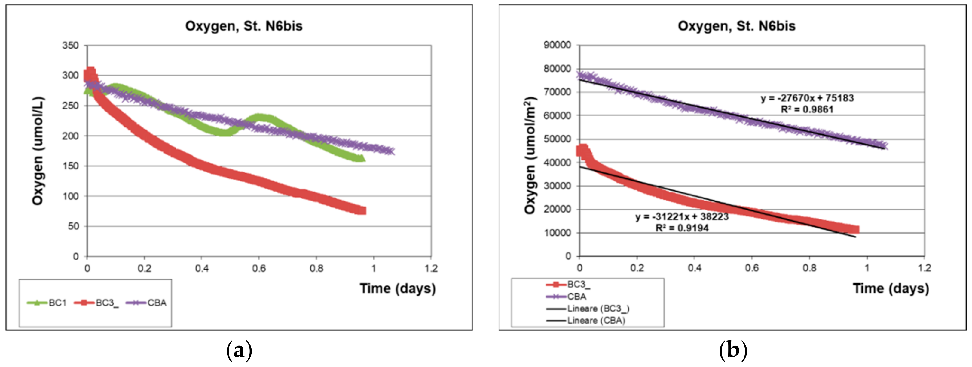
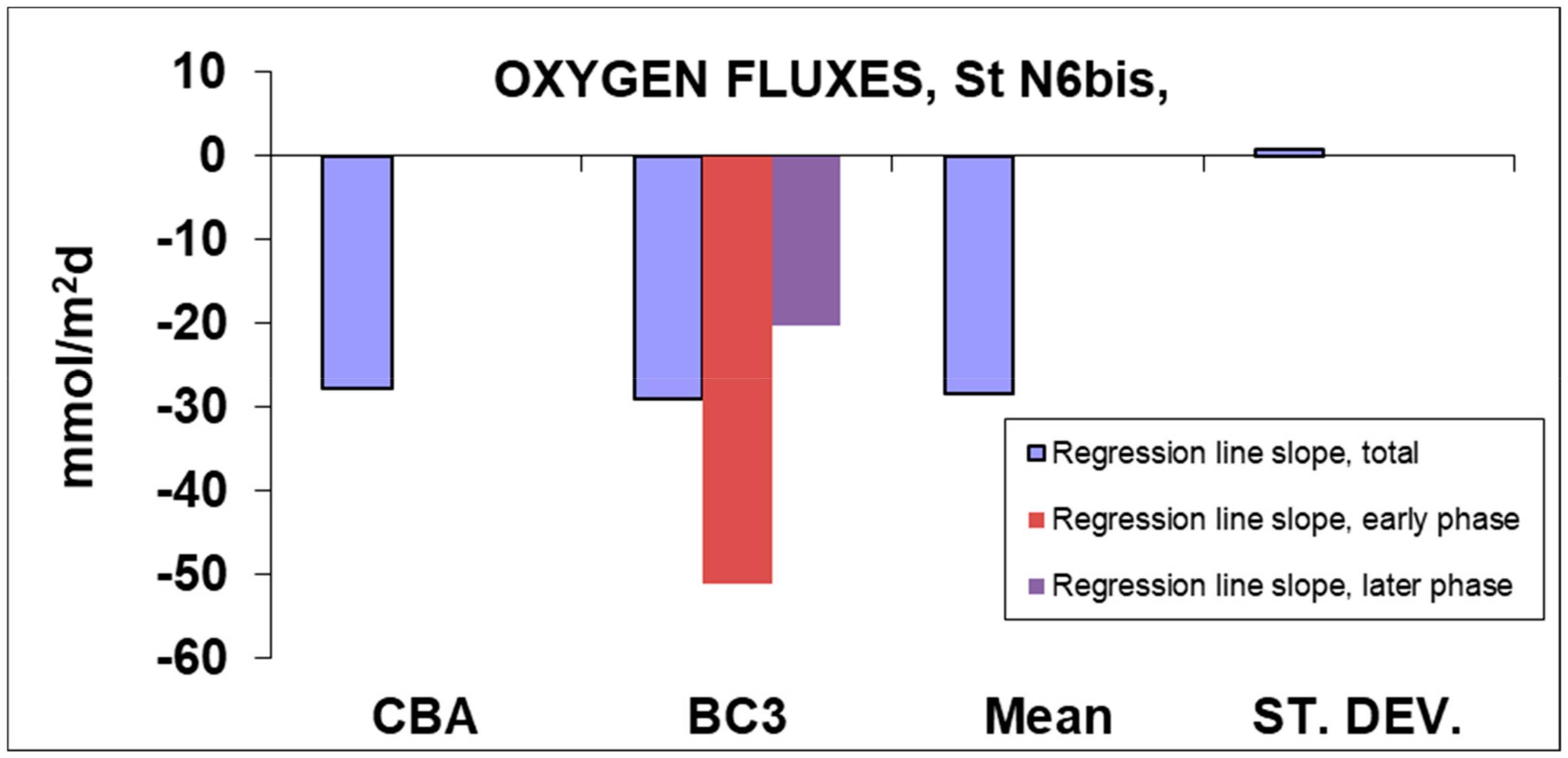
| . | Regression Line Slope, Total | Regression Line Slope, Early Phase | Regression Line Slope, Later Phase |
|---|---|---|---|
| Oxygen | mmol/m2*days | ||
| CBA | −27.670 | - | - |
| BC3 | −28.903 | −51.087 | −20.144 |
| Mean | −28.287 | - | - |
| ST. DEV. | 0.872 | - | - |
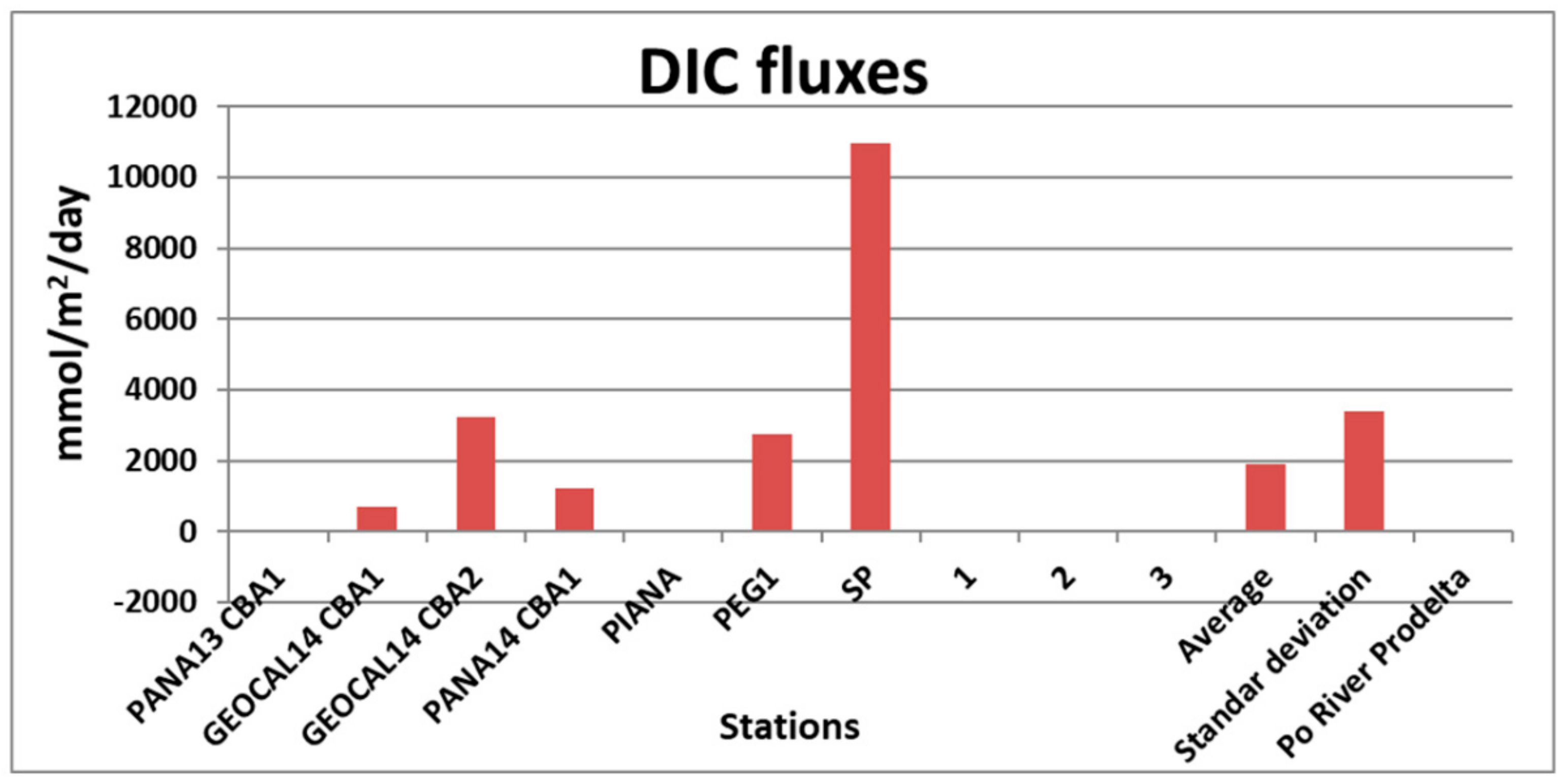
| Cruise | Stations | Flux (mmol/m2·d) |
|---|---|---|
| PANA13 | PANA13 CBA1 | 60.60 |
| GEOCAL14 | GEOCAL14 CBA1 | 689.30 |
| GEOCAL14 | GEOCAL14 CBA2 | 3223.90 |
| PANA14 | PANA14 CBA1 | 1212.70 |
| PANA15 | PIANA | −17.99 |
| PANA15 | PEG1 | 2750.60 |
| PANA15 | SP | 10978.00 |
| PANA15B | 1 | 61.54 |
| PANA15B | 2 | −4.41 |
| PANA15B | 3 | −19.29 |
| - | - | |
| Average | - | 1893.49 |
| Standard deviation | - | 3408.76 |
| Po River Prodelta average | - | 29.00 |
© 2019 by the authors. Licensee MDPI, Basel, Switzerland. This article is an open access article distributed under the terms and conditions of the Creative Commons Attribution (CC BY) license (http://creativecommons.org/licenses/by/4.0/).
Share and Cite
Spagnoli, F.; Penna, P.; Giuliani, G.; Masini, L.; Martinotti, V. The AMERIGO Lander and the Automatic Benthic Chamber (CBA): Two New Instruments to Measure Benthic Fluxes of Dissolved Chemical Species. Sensors 2019, 19, 2632. https://doi.org/10.3390/s19112632
Spagnoli F, Penna P, Giuliani G, Masini L, Martinotti V. The AMERIGO Lander and the Automatic Benthic Chamber (CBA): Two New Instruments to Measure Benthic Fluxes of Dissolved Chemical Species. Sensors. 2019; 19(11):2632. https://doi.org/10.3390/s19112632
Chicago/Turabian StyleSpagnoli, Federico, Pierluigi Penna, Giordano Giuliani, Luca Masini, and Valter Martinotti. 2019. "The AMERIGO Lander and the Automatic Benthic Chamber (CBA): Two New Instruments to Measure Benthic Fluxes of Dissolved Chemical Species" Sensors 19, no. 11: 2632. https://doi.org/10.3390/s19112632