Electrochemical Fingerprint of Arsenic (III) by Using Hybrid Nanocomposite-Based Platforms
by
 and
and
Gheorghe Melinte
1,†, 
Oana Hosu
1,2,†, 
Mariagrazia Lettieri
2,
Cecilia Cristea
1 and
and
Giovanna Marrazza
2,3,*
1
Department of Analytical Chemistry, Faculty of Pharmacy, “Iuliu Haţieganu” University of Medicine and Pharmacy, Pasteur 4, 400349 Cluj-Napoca, Romania
2
Department of Chemistry ”Ugo Schiff”, University of Florence, Via della Lastruccia 3, 50019 Sesto Fiorentino (Fi), Italy
3
Instituto Nazionale Biostrutture e Biosistemi (INBB), Unit of Florence, Viale delle Medaglie d’Oro 305, 00136 Roma, Italy
*
Author to whom correspondence should be addressed.
†
Authors with equal contribution.
Sensors 2019, 19(10), 2279; https://doi.org/10.3390/s19102279
Submission received: 21 March 2019
/
Revised: 14 May 2019
/
Accepted: 15 May 2019
/
Published: 17 May 2019
(This article belongs to the Special Issue Electrochemical Nanobiosensors)
Abstract
:Arsenic, one of the most abundant mineral and also one to the most toxic compounds. Due to its high toxicity sensitive analytical methods are highly important, taking into account that the admitted level is in the range of µg L−1. A novel and easy to use platform for As(III) detection from water samples is proposed, based on gold and platinum bi metallic nanoparticles and a conductive polymer (polyaniline). The electrochemical detection was achieved after optimization of cathodic pre-concentration and stripping parameters by square wave anodic stripping voltammetry at modified screen-printed carbon-based electrochemical cells, proving its applicability for disposable and cost-effective in situ analysis of arsenic.
1. Introduction
Arsenic (As) is the 12th most abundant mineral in the human body and one of the most 20 abundant minerals in the Earth’s crust [1]. It is considered one of the most toxic compounds having a high carcinogenic potential. The exposure to arsenic can cause DNA mutation which can lead to an aberrant gene expression and carcinogenesis [2]. Many regions around the world are affected by arsenic contamination; it appears mostly in areas like Argentina, Bangladesh, China, India, Nepal, Mexico, Pakistan, and parts of the USA. In some waters in Bangladesh, the arsenic level can reach up to 2500 µg L−1 while the WHO admitted level is only 10 µg L−1 [3]. Moreover, recent studies showed that arsenic contamination is a public health menace in several Italian areas as high levels of arsenic (up to 295 µg L−1) can be found in groundwater due to the volcanic origins of the territory [4,5]. Furthermore, arsenic values in drinking water were chronically detected between 20 and 50 μg L−1 [4]. As regulations from the EU were delayed for several years to implement more controlled water content, the inhabitants were subjected to long exposure of arsenic at low-medium levels.
It appears in the atmosphere mostly as As(III) and As(V) inorganic salts, and it is usually converting one form to another in solution [6]. Arsenic’s adverse effects are strongly related with the dose, species, and the duration of exposure. A fast and high-level exposure leads to acute effects like nausea, diarrhea, abdominal pain or death. If the exposure is made slow and with low amounts of arsenic, chronic effects will occur, like skin irritation, cardiovascular events, or even cancer, due to its carcinogenic potential [7].
Hence, analytical techniques capable of detecting trace levels of As are highly required. Currently used analytical methods for arsenic detection include atomic absorption and emission spectrometry, mass spectrometry, and high-performance liquid chromatography [8]. Although these methods present good limits of detection (LOD) and high sensitivities, several limitations should be mentioned: the need of complex equipment and skilled personnel, complicated sample preparation, time consuming analysis, and most important the poor suitability for in situ detection and routine analysis.
Electrochemical sensors have been widely applied to sensitively detect a plethora of chemical and biological analytes. The use of electrochemical platform has advantages as multiplexing, portability, cost-effectiveness, and friendly use. In the last decade electrochemical sensors proved to be promising alternatives to qualitatively and quantitatively detect arsenic from different matrices. Different electrochemical methods have been commonly used such as linear sweep anodic stripping voltammetry (LSASV), square wave anodic stripping voltammetry (SWASV), differential pulse anodic stripping voltammetry (DPASV), cathodic stripping voltammetry (CSV), cyclic voltammetry (CV), and chronopotentiometry [9,10]. The methods involving a potential-assisted electrochemical pre-concentration prior the stripping voltammetry revealed to be more sensitive towards As and continues to be one of the most powerful techniques for its electrochemical determination. As(III) is electrochemically reduced to As(0) at the surface of working electrode by cathodic pre-concentration deposition at a controlled time (tdep) and potential (Edep) [11]. Therefore, the optimization of these parameters is of crucial importance to obtain the sensor with the best analytical performance. Following the pre-concentration step, the anodic stripping scan is performed to achieve the re-oxidation of As(0) to As(III). However, oftentimes long accumulation period is required and poor selectivity is reported when applied in complex matrices [11]. Therefore, different strategies have been followed in order to increase the sensitivity and the selectivity of electrochemical sensors. Generally, the integration of nanocomposite materials in sensors’ development leads to increased overall analytical performance, while selectivity is provided by the use of biomolecules that specifically react with the target analyte [12].
A great deal of progress has been made in the electrochemical detection of arsenic. One of the first developed electrochemical sensors was based on the co-precipitation of arsenic with copper and selenium followed by its reduction to arsine by means of a mercury drop electrode. The sensor had a low LOD of 0.52 µg L−1, but the selectivity was not at a high level, Cu(II) being an important interferent. Even more, the experimental conditions are highly toxic and unlikely to be applied for in situ determination [13]. As the years passed, new types of electrodes and platforms were developed, while nanoparticles gained more and more attention. Gold nanoparticles (AuNPs) has been attracting interest for As detection due to their high adsorption capacity and abundant availability [10]. In 2008, Rassaei et al. developed a sensor for As(III) water detection using a boron-doped diamond electrode and AuNPs. Even though the method was proved to be sensitive as a 1 µg L−1 limit of detection was achieved, the electrochemical detection method requires relatively long accumulation time (300 s) of As at the modified-electrode surface [14]. Recent years showed an increase in the number of chemical sensors based on different nanoparticles and nanomaterials for arsenic determination. Carbon electrodes were modified with different nanoparticles obtained from metals such as Mn, Co, Fe, Sn, Au, Pt each one with its advantages and disadvantages. A series of authors report arsenic electrochemical detection using glassy carbon electrodes (GCE) modified with AuNPs and different other nanomaterials [8]. Chowdhury et al. developed a AuNP/polyaniline sensor, that offered a LOD of 0.4 µg L−1 for arsenic [15]. Electrodeposited PtNPs at GCEs lead to a LOD for arsenic using LSV of 0.05 µg L−1 [16]. Even though there are many metallic nanoparticles based electrochemical sensors for arsenic, with good analytical performance, the most used immobilization electrode (GCE) increases the detection time and does not offers the possibility for in situ detection, like the screen-printed electrochemical cells (SPE) do. As bioelements, aptamers and DNA proved to be extremely selective, but require long preparation time for sensors [17]. By contrast, nanoparticles have the ability to enhance the sensitivity by increasing the active surface of the electrodes due to their electronic, chemical, and physical properties, leading to low detection limits and improved signal-to noise ratios [18]. Several types of metallic nanoparticles are currently used for single or array of electrodes, presenting the significant advantage of being prepared by the electrochemical method starting from the corresponding metallic salts.
Recently, bimetallic NPs were integrated into sensor design, due to their improved electrocatalytic activity and conductivity. They (i.e., Au-Ag, Au-Pt, Au-Cu, etc.) could be easily integrated in different types of matrices for 3D porous networks capable of detecting heavy metals or other pollutants [8].
In this paper, a sensitive sensor for arsenic detection in water samples is presented based on a mixed film of polyaniline (PANI) and bimetallic composite Au-PtNPs. PANI is one of the most promising conducting polymers. Between its advantages, the fast synthesis, low cost and high electrochemical conductivity are the most important. Nevertheless there are some drawbacks of the PANI that limit its application like low power density and cycling stability [17,19,20]. To overcome these limitation other materials are often incorporated with PANI in the synthesis of novel electrochemical platforms [21]. Different strategies were evaluated in order to obtain the sensor with the best analytical performance for As sensing, namely modified screen-printed carbon electrode (SPCE) with different nanostructured surfaces: gold nanoparticles (AuNPs/AuSPCE), platinum nanoparticles (PtNPs/SPCE), bimetallic (Au-PtNPs/SPCE), polymer (PANI/SPCE), and composite (Au-PtNPs/PANI/SPCE). Hence, the electrolyte used during the measurements plays a crucial role in the sensitive detection of arsenic. An exhaustive study of experimental conditions was addressed for the electrochemical fingerprinting of As(III) for the development of a fast and disposable sensor. The electrochemical detection was achieved after optimization of cathodic pre-concentration and stripping parameters by SWASV at modified SPCEs, proving its applicability for disposable and cost-effective in situ analysis of arsenic. Nevertheless, the overall sensor fabrication and analysis time was 5 min for Au-PtNPs/SPCE platform, and 12 min for Au-PtNPs/PANI/SPCE platform, respectively, allowing the As(III) detection in nanomolar range.
2. Materials and Methods
2.1. Reagents and Instrumentation
All chemicals were of analytical grade and all solutions were prepared in deionized water from a Mili-Q System (Milipore, Italy, 18 MΩ·cm). Lithium chloride (LiCl), sodium arsenite (NaAsO2), aniline (C6H5NH2), and hydrochloric acid 30% (HCl) were purchased from Merck (Darmstadt, Germany). Potassium chloride (KCl), potassium ferrocyanide (K4[Fe(CN)6]), potassium ferricyanide (K3[Fe(CN)6]), sulphuric acid 97% (H2SO4), perchloric acid (HClO4), tetrachloroauric acid (HAuCl4), hexachloroplatinic acid (H2PtCl6) were purchased from Sigma-Aldrich. Heavy metal solutions were prepared from Cu(II), Pb(II), and Hg(II) standard solutions of AAS grade purchased from Fluka (Cinisello Balsamo, Milan, Italy).
All electrochemical measurements were performed on an Autolab potentiostat PGSTAT302, using NOVA software 1.10 and 1.11. Screen-printed carbon electrochemical cells (SPCE) with a 3 mm diameter carbon working electrode, Ag/AgCl pseudo-reference electrode, and carbon as a counter electrode were purchased from EcoBioServices (Sesto Fiorentino, Florence, Italy).
2.2. Preparation of Composite Platforms
Nanocomposite modified electrodes were obtained by electropolymerization of aniline and electrodeposition of AuNPs, PtNPs and mixtures of these from their metallic salts (HAuCl4 and H2PtCl6). Aniline was electropolymerized by cyclic voltammetry (CV) through a procedure previously described [12,18]. In brief, 50 µL of 2.5 mM C6H5NH2 in 50 mM HClO4 solution was drop casted onto SPCE. The potential was scanned from –0.4 V to +0.8 V for 10 cycles at 50 mV s−1 scan rate. The electrodeposition of nanoparticles was adapted for SPCE from a method previously described [22]. AuNPs and PtNPs were electrodeposited at SPCE and PANI/SPCE by applying a fixed potential of −0.2 V for 130 s from solutions containing:
- 0.2 mM HAuCl4 in 0.5 M H2SO4;
- 2 mM HAuCl4 in 0.5 M H2SO4;
- 4 µM H2PtCl6 in 0.5 M H2SO4;
- 1 mM H2PtCl6 in 0.5 M H2SO4;
- and combination of these.
Electrochemical characterization of the developed platforms by cyclic voltammetry measurements was performed in a 5 mM [Fe(CN6)]4−/3− in 0.1 M KCl solution at different rates (25–150 mV s−1), using a potential range from −0.50 to +0.80 V and a potential step of 4 mV.
2.3. Measurement Procedure
SWASV was performed in different electrolytes like (i) lithium chloride (6.0 M LiCl in 0.1 M H2SO4), (ii) potassium chloride (0.1 M KCl solution containing 0.1 M HCl), and (iii) hydrochloric acid (0.1 M HCl) for the determination of arsenic from a 50 mM NaAsO2 aqueous solution which was diluted to the desired concentrations using the electrolyte chosen for the experiment. SWASV conditions were: conditioning potential (Econd) +0.70 V for 30 s, cathodic deposition potential (Edep) −0.5 V for (tdep) 60 s, and equilibration time (teq) of 30 s; and stripping parameters: 45 mV s−1 scan rate, 0.003 V step potential, and 15 Hz frequency (f). The measurements were performed immersing the modified electrochemical cell in a 5.0 mL solution. Stirring conditions were used during the accumulation step for a more uniformly deposition using a Metrohm 728 stirrer. Cathodic pre-concentration parameters (Edep and tdep) were optimized and the best electrolyte solution was chosen among these experiments.
3. Results and Discussion
In a first attempt, different types of modified screen-printed electrodes were tested in order to obtain the best analytical signal of As(III) electrochemical oxidation of pre-concentrated As(0) with minimum of modification steps. The SPCEs were preferred due to their possibility of single use, excluding thus the contamination issues and allowing in a future step, the integration into a decentralized analytical device.
3.1. Electrochemical Characterization of the Platform Configurations
Unmodified and modified SPCE with different nanostructured films: gold nanoparticles (AuNPs/AuSPCE), platinum nanoparticles (PtNPs/SPCE), bimetallic (Au-PtNPs/SPCE), polymer (PANI/SPCE), and composite (Au-PtNPs/PANI/SPCE) were characterized by cyclic voltammetry (CV) in 5 mM [Fe(CN6)]4−/3− in 0.1 M KCl solution. Table 1 shows the investigated electrochemical platform architectures. Choosing the best platform for further optimization in order to develop the sensor for As(III) fingerprinting, different parameters were taken into consideration. Hence, beside the electrocatalytic effect, the efficiency of the electrode design in terms of reproducibility, costs and fabrication time of the platforms towards arsenic detection were also evaluated. The platforms that offered the best results, regarding the above description, are represented in Figure 1c.
Therein, the effective surface area of all six platform designs were estimated by CV following Randles–Sevcik Equation (1) [23]:
where Ip is the response peak current (A), n is the electrons transfer number, A is the electrochemical effective area (cm2), D is the diffusion constant of 5.0 mM K3Fe(CN)6 in 0.1 M KCl (6.2 × 10⁻⁶ cm2 s−1), v is the scan rate (V s−1), and C relates to the bulk concentration of the K3Fe(CN)6 redox probe (mol cm−3).
Ip = (2.69 × 10⁵)n3/2AD1/2 v1/2C
Based on the above formula, the electrochemical effective area can be calculated from the slope of the Ip-v1/2 relations. Figure 1a,b presents the CVs of 5.0 mM K3Fe(CN)6 in 0.1 M KCl solution registered at (IV)Au-PtNPs/SPCE at scan rates between 25 and 150 mV s−1 and the linear plots of the anodic and cathodic peak currents versus square root of scan rate, respectively. The electrochemical surface area of the platforms was calculated and compared with the one of bare SPCE (%/bare SPCE geometric area).
It can be seen from Figure 1c that the effective surface area of platform (I)AuNPs/SPCE increases with a factor of 1.33 compared with bare SPCE. Moreover, two platform architectures were evaluated for the electrodeposition of PtNPs at SPCE with respect to the H2PtCl6 solution concentration. It can be clearly seen that the use of a more concentrated chloroplatinic acid solution is not pertinent as the electrocatalytic effect towards the redox probe is approximately the same for (II)PtNPs/SPCE (127%) and (III)PtNPs/SPCE (130%), respectively. Hence, when the bimetallic platform (IV)Au-PtNPs was designed, a slightly higher effective surface area was obtained (136%) and, in particular, when in combination with PANI, amplified peak currents and more reversible redox peaks were obtained, which were related to around a two-fold increase in the electroactive surface area of (VI)Au-PtNPs/PANI/SPCE (192%) compared to bare SPCE. The synergistic effect of the nanocomposite hybrid film could be observed as (V)PANI/SPCE exhibited only an increase of the electrode surface area of 139% compared to bare SPCE, thus proving improved electrocatalytic effect of platform (VI). Moreover, the time needed for platform development should be considered to provide an efficient and rapid sensor. The metal nanoparticles-modified SPCE fabrication involves a constant potential assisted electrodeposition for 130 s, while electropolymerization of aniline at SPCE occurs after 480 s. All results are reported in triplicate with a RSD% lower than 5%. Therefore, overall characteristics of the developed platforms were considered when applied for arsenic fingerprinting. AuNPs and PtNPs are excellent electrical conductors and their incorporation in the sensor’s design improves the electron transfer during the electrochemical processes. In addition, it was demonstrated that the Pt sites work as atomic hydrogen and molecular hydrogen generator in H2SO4 solution which can chemically reduce the As(III) to As(0) and, therefore, enhance the cathodic pre-concentration of As(0) at both the Pt sites and the neighboring Au sites [22]. Therefore, the platforms with the best analytical performance were chosen for further experiments namely (IV)Au-PtNPs/SPCE and (VI)Au-PtNPs/PANI/SPCE, respectively.
3.2. Optimization of the Experimental Conditions
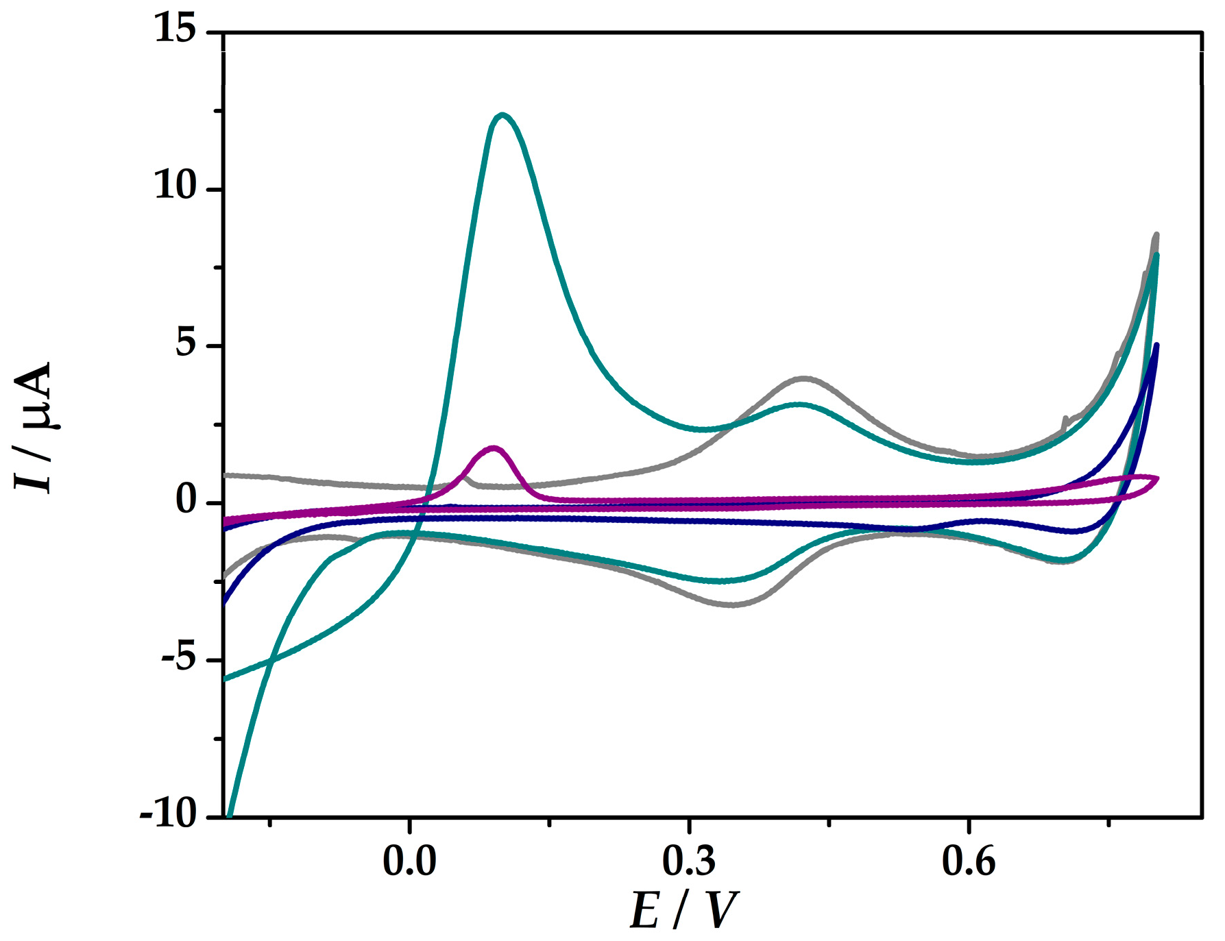
Figure 2 shows the cyclic voltammograms of the developed platforms (IV) and (VI) in 0.1 M HCl and in the presence of 1 mM As(III) in 0.1 M HCl without any prior pre-concentration step. No redox peaks were found in 0.1 M HCl (iii) free of As (III) at Au-PtNPs/SPCE in the potential range from −0.5 V and +0.8 V, while at Au-PtNPs/PANI/SPCE the redox pair at around 0.38 V was assigned to the oxidation/reduction of PANI. Both platforms show a peak at around 0.1 V, which is assigned to the electrooxidation of As(0). At (VI)Au-PtNPs/PANI/SPCE, the peak current intensity was 11.6 µA, while at (IV)Au-PtNPs/SPCE lower current intensity was obtained (1.94 µA), thus proving an enhanced sensitivity of As(III) at platform (VI).
The methods involving a potential-assisted electrochemical pre-concentration for trace metals sensing continues to be one of the most powerful techniques for heavy metal detection. Therefore, SWASV measurements were employed for As(III) sensing at the developed nanostructured platforms in order to obtain improved sensitivities. The mechanism for the enhanced SWASV signaling of As(III) involves a cathodic pre-concentration step of As(0) from a As(III) solution followed by the anodic stripping from the electrode surface characteristic for the re-oxidation of As(0) to As(III). Therefore, the magnitude of the electrooxidation peak was used for the quantitative evaluation of As(III).
In order to obtain the best results for As(III) fingerprinting, several electrolytes (6.0 M LiCl in 0.1 M H2SO4 (i), 0.1 M KCl in HCl (ii), and 0.1 M HCl (iii)) were tested for the optimized designed platforms both in the presence and the absence of As(III). Several parameters like the As(III) deposition (pre-concentration) time (tdep) and potential (Edep), electrochemical method, the response and the linearity of the developed platforms towards As(III) were studied and optimized for all electrolyte solutions.
Firstly, the fingerprinting of As(III) was assessed in electrolyte (i). Figure 3a shows the peak currents intensities obtained in a solution containing 3 µM As(III) in 6.0 M LiCl in 0.1 M H2SO4 (i) at (IV)Au-PtNPs/SPCE where the SWASV parameters were optimized taking into account two cathodic pre-concentration times of 120 s (A) and 240 s (B) and potentials of −0.35 V and −0.50 V, respectively. Foremost, the influence of the pre-concentration time was considered. It can be observed that at tdep = 120 s pre-concentration time there is a great difference in the peak current values when applying Edep = −0.35 V (45.54 µA) compared to Edep = −0.5 V (6.66 µA). For longer cathodic pre-concentration time (tdep = 240 s), an increase in the peak current intensity (27.64 µA) was obtained for Edep = −0.5 V, whereas for Edep = −0.35 V a slightly decrease down to 34.54 µA was observed. Although higher peak current intensities were obtained at –0.35 V pre-concentration applied potential. When increasing the deposition time, the results showed lower current intensities for higher As(III) levels. Moreover, the results showed better %RSD values when applying lower deposition potential (Edep = −0.5 V).
Secondly, for a better understanding of the cathodic pre-concentration step, two arsenic concentration solutions were tested, namely 3 µM and 30 µM As(III) in electrolyte solution (i). Therefore, in order to increase the sensitivity of the sensor, different cathodic pre-concentration deposition time was considered (120 s, 180 s, and 240 s).
At tdep = 120 s, irrelevant results in arsenic anodic stripping were obtained as the peak intensity of the more concentrated As(III) solution revealed lower current values due to a probably low sensitivity at higher concentration levels. When increasing the pre-concentration time up to 180 s, better analytical response of 36.1 µA and 48.0 µA were obtained at modified electrodes for 3 µM and 30 µM As(III) solution, respectively. The results demonstrate higher electrocatalytic effect of the (IV)Au-PtNPs/SPCE platform when the potential was applied for tdep = 240 s by comparing the peak current intensity ratio (a two-fold increase) obtained in 3 µM and 30 µM As(III) solution (Figure 3b). However, high cathodic pre-concentration time could lead to irreproducible results as difficulties in stripping the As(0) from the electrode surface could be encountered, leading thus to a decrease of the sensors’ reproducibility in terms of %RSD. Therefore, different strategies should be followed for a more sensitive detection of arsenic.
The effect of HAuCl4 solution concentration was studied for this supporting electrolyte, using 2 mM and a 0.2 mM solutions of HAuCl4 in the HAuCl4-H2PtCl6 mixture and testing by SWASV measurements in a 30 µM As(III) in electrolyte solution (i). By increasing the HAuCl4 concentration and the Au-PtNPs ratio from the sensor structure, higher oxidation peak current intensities of As(III) were obtained, allowing the detection of trace levels of As(III). Further experiments were performed using platform number (IV) obtained by electrochemical deposition of Au-PtNPs at SPCE from a mixture containing 2 mM HAuCl4 and 4 µM H2PtCl6 in 0.5 M H2SO4 solution.
In order to increase both sensitivity and reproducibility of the sensors compared with the results obtained in electrolyte (i), another electrolyte solution was used, namely 0.1 M KCl in 0.1 M (ii).
Figure 4a shows the peak current intensities recorded by SWASV at (IV)Au-PtNPs/SPCE from a 3 µM As(III) solution in electrolyte (ii) using a tdep = 120 s at two different deposition potentials Edep: −0.35 V and −0.5 V. The higher peak height was obtained after the deposition of As(0) from a As(III) solution at −0.50 V potential (22 µA) compared to −0.35 V (4.11 µA). Therefore, −0.50 V cathodic pre-concentration potential of As(0) was used for further optimization tests.
In the next step, the cathodic potential-assisted deposition time was optimized as it plays an important role in the sensitivity and reproducibility of the obtained sensors (Figure 4b). The electrochemical experiments were conducted at (IV)Au-PtNPs/SPCE in solutions containing 3 µM and 9 µM of As(III), respectively. The parameters of the cathodic pre-concentration of As(0) were Edep of –0.50 V and tdep of 120, 180, and 240 s, respectively. Increased values of the As(0) anodic stripping peaks are observed in correlation with the increase in the deposition time from 120 s to 180 s from a solution containing 3 µM As(III). Therefore, after cathodic pre-concentration of tdep = 120 s a peak current of 22.0 µA was obtained, whereas after tdep = 180 s the peak current height was 110.95 µA, respectively. By contrast, when comparing the results obtained in 9 µM As(III) solution, little changes in the peak current values were observed after 180 s cathodic pre-concentration (121.35 µA), thus proving the low sensitivity of the sensor. When applying 240 s deposition time show an increase in the peak currents up to 59.35 µA and 112.92 µA from solutions of 3 µM As(III) and 9 µM As(III) solution in 0.1M KCl in 0.1M HCl, respectively. Although the results show an increase in the sensitivity of the sensor compared to the one using 120 s deposition time, high %RSD values of 18% and 26% were obtained at (IV)Au-PtNPs/SPCE from solutions containing 3 µM As(III) (blue) and 9 µM As(III) (grey) in 0.1 M KCl in 0.1 M HCl, thus proving its low reproducibility.
As could be seen from the previous experiments the As(III) fingerprint was assessed in two different supporting electrolytes (i and ii). It can be concluded that –0.5 V cathodic pre-concentration potential showed the best results in both electrolytes to reduce the As(III) to As(0) at the electrode surface. The time of the potential-assisted deposition was evaluated. Although improved sensitivities were obtained when at tdep = 240 s in electrolytes (i) and (ii), the relatively high %RSD values and long analysis time reduce the utility for future possible in situ analysis.
The influence of the KCl salt was also considered, thus the optimization of the electrocatalytic effect of the (IV)Au-PtNPs/SPCE platform towards arsenic was evaluated as well in 0.1 M HCl supporting electrolyte (iii) free of KCl.
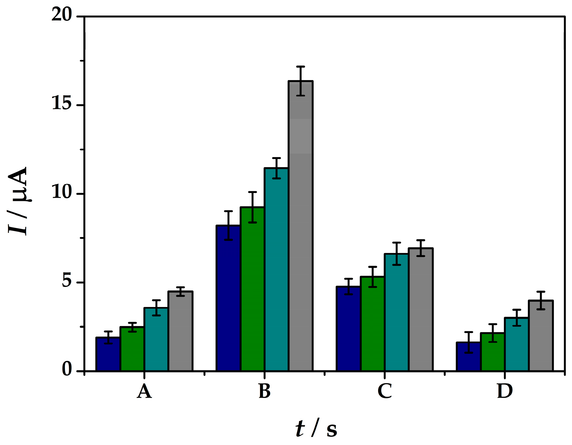
In this case different concentrations of the As(III) solutions were tested in the range between 33–200 nM in order to see the influence of the pre-concentration time for As(III) detection. It can be observed from Figure 5 not only the inversely correlation between the peak current intensities obtained within the SWASV tests with the arsenic cathodic pre-concentration period at the platform surface, but also the linear correlation with the As(III) concentration solutions. At tdep = 60 s of pre-concentration potential-assisted deposition of As(III) at the modified electrode surface shows peak current intensities from 1.90 µA at 33 nM to 4.49 µA for 200 nM As(III) solutions in electrolyte (iii). Although, 120 s of deposition offers the best current intensity increase from 8.21 µA at 33 nM to 16.34 µA for 200 nM As(III), the increase does not follow a linear correlation with the As(III) concentration. At 180 s deposition time lower current intensities were obtained and the linear correlation within the arsenic concentration was lost. For 240 s deposition time of As(0) the current intensities drop off to lower values as 1.62 µA at 33 nM to 3.98 µA for 200 nM As(III) solutions in electrolyte (iii). Therefore, considering the ratio between the sensitivity offered by the sensor and the analysis time needed, tdep = 60 s and Edep = −0.5 V in 0.1 M HCl solution were used as a cathodic pre-concentration step during the SWASV analysis method at (IV)Au-PtNPs/SPCE platform.
Finally, after all optimization steps made for each electrolyte solution, an overall comparison is presented taking into consideration the oxidation peak current intensities obtained at platform (IV) in a solution containing 3 µM As(III) in 6.0 M LiCl in 0.5 M H2SO4 (i), 0.1 M KCl in 0.1 M HCl (ii), and 0.1 M HCl (iii), respectively. Firstly, As(III) was electrochemically reduced by potential-assisted pre-concentration using at Edep of −0.50 V for 120 s. Platform (IV) revealed the highest electrocatalytic effect against As (6.66 µA) in electrolyte (i), compared with the SWASV oxidation peaks values of 5.07 µA and 2.76 µA obtained in electrolyte (ii) and (iii), respectively.
At trace levels of arsenic, the sensitivities of the sensor is considerably reduced in electrolytes (i) and (ii) compared to the one obtained in electrolyte (iii). The fact that these electrolytes offers a peak only at high levels of As(III) makes the electrolyte (iii) the best solution for sensing As(III) at the developed platform. Nevertheless, the overall sensor fabrication and analysis time was 5 min for platform (IV)Au-PtNPs/SPCE, and 12 min for platform (VI)Au-PtNPs/PANI/SPCE, respectively; thus, proving its high efficiency as a possible future disposable sensor for arsenic sensing.
3.3. Arsenic Electrochemical Fingerprint Detection
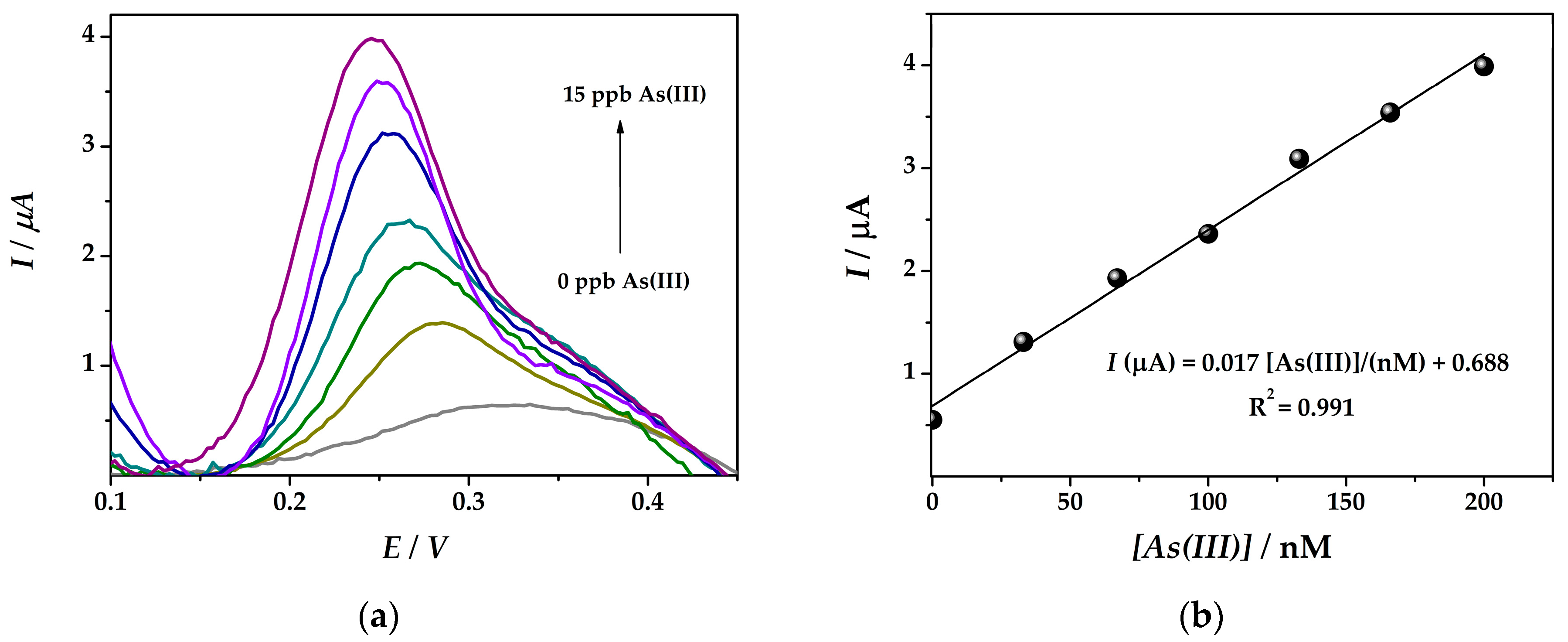
The electrochemical detection of arsenic was performed at platforms (IV)Au-PtNPs/SPCE and (VI)Au-PtNPs/PANI/SPCE using the optimized square wave anodic stripping voltammetry procedure as previously reported. Different concentration solutions of As(III) (33–200 nM) in a 0.1 M HCl (iii) solution were tested using SWASV by applying a pre-concentration deposition potential of −0.50 V for 60 s in the potential range from −0.20 to +0.50 V at 45 mV s−1.
A linear correlation between the arsenic concentration and the signal obtained by SWASV in 0.1 M HCl at bimetallic nanocomposite electrode surface (IV) was obtained between 33 nM and 200 nM As(III) with a sensitivity of 0.017 µA nM−1 and a limit of detection (LOD) of 19.7 nM (Figure 6). The detection limit was calculated from three times the standard deviation of the regression equation divided by its slope [23].
Hence, the response of platform (VI)Au-PtNPs/PANI/SPCE was evaluated in the optimized conditions for arsenic detection as revealed the highest electrocatalytic effect towards 5 mM [Fe(CN6)]4−/3− in 0.1 M KCl solution and by CV characterization in 1 mM As(III) in electrolyte (i). By contrast, when applied for arsenic sensing in trace levels, platform (VI) exhibited lower current intensities compared to platform (IV) and offered a linearity in the range between 0.1–1.25 mM As(III) with the following equation I(µA) = 6.116 [As(III)/mM] + 6.129; R2 = 0.994. This could be probably due to the incorporation of the deposited As(0) into the PANI matrix and lower catalytic effect of the electrogenerated noble metal particles. Moreover, the Au-Pt sites could be entrapped into the polymer film and therefore the enhanced cathodic pre-concentration would not occur. Although, for high levels of As(III), (VI)Au-PtNPs/PANI/SPCE could be applied.
Both platforms could be used for fingerprinting As(III) in 0.1 M HCl solution, where (IV) provided better responses for low levels of As(III), meanwhile the platform containing PANI (VI) could be useful for detecting As(III) levels in milimolar range.
3.4. Interferences
As(III) is rarely found in water or sand by itself. Between all the possible interference metals, that can be found alongside As(III), Cu(II), Pb(II), and Hg(II) are very common and can easily interfere in the detection of the desired metal.
SWASVs were performed at platform (IV) in different solutions containing 3 µM Hg(II), Cu(II), Pb(II), and As(III) in 0.1 M HCl using the previously optimized method. In addition to the specific oxidation peak of As(0) to As(III) at +0.20 V, a peak separation was observed when in combination with Hg(II) (+0.25 V) and Cu(II) (+0.26 V) interferences. Nevertheless, even the signals of Cu(II) and Hg(II) are in a close potential range to the one of As(III), and their current intensities are much lower (Table 2).
It was thus shown that using the optimized (IV)Au-PtNPs/SPCE platform it was possible to detect As(III) even in the presence of other metallic ions.
4. Conclusions
A novel and easy to use nanohybrid platform based on a mixed film of PANI and bimetallic composite Au-PtNPs for As(III) electrochemical fingerprinting was optimized. In addition to many advantages of PANI, like the fast synthesis, low cost, and high electrochemical conductivity, to overcome its drawbacks PANI was used in hybrid platforms with Au-PtNPs. In order to optimize a sensor for As(III) detection in water several electrolytes were evaluated in order to obtain the best analytical performance for As sensing. The electrochemical detection with a good limit of detection was achieved after optimization of cathodic pre-concentration and stripping parameters by square wave anodic stripping voltammetry at modified screen-printed carbon-based electrochemical cells. The sensors allowed the As(III) determination in the range between 0 and 200 nM As(III) and a LOD of 19.7 nM was obtained. The platforms with the best analytical performance were Au-PtNPs/SPCE and Au-PtNPs/PANI/SPCE. Hence, first the platform revealed better sensitivity in solutions of trace levels of As(III), while the second platform offered better results for higher concentrations of As(III). Nevertheless, the overall sensor fabrication and analysis time was 5 min for platform Au-PtNPs/SPCE, and 12 min for platform Au-PtNPs/PANI/SPCE, respectively. These preliminary studies prove the practical applicability and high efficiency as possible future disposable and cost-effective sensors for in situ arsenic sensing.
Author Contributions
Conceptualization: G.M. (Gheorghe Melinte) and O.H.; methodology: G.M. (Gheorghe Melinte) and O.H.; validation: G.M. (Gheorghe Melinte) and O.H.; formal analysis: M.L., G.M. (Gheorghe Melinte), and O.H.; resources: G.M. (Giovanna Marrazza) and C.C.; writing—original draft preparation: G.M. (Gheorghe Melinte), O.H., C.C., and G.M. (Giovanna Marrazza); writing—review and editing: G.M. (Gheorghe Melinte), O.H., C.C., and G.M. (Giovanna Marrazza); supervision: G.M. (Giovanna Marrazza) and C.C.; project administration: G.M. (Giovanna Marrazza); funding acquisition: G.M. (Giovanna Marrazza) and C.C.
Acknowledgments
G.Me., O.H., and C.C. acknowledge the Romanian National Authority for Scientific Research and Innovation, CCCDI-UEFISCDI, project number ERANET-RUS-PLUS-PLASMON-ELECTROLIGHT/46/2018, within PNCDI III.
Conflicts of Interest
The authors declare no conflict of interest.
References
- Cinti, S.; Politi, S.; Moscone, D.; Palleschi, G.; Arduini, F. Stripping Analysis of As(III) by means of screen-printed electrodes modified with gold nanoparticles and carbon black nanocomposite. Electroanalysis 2014, 26, 931–939. [Google Scholar] [CrossRef]
- Roy, P.; Saha, A. Metabolism and toxicity of arsenic: A human carcinogen Sources of different forms of arsenic: Human exposure and chronic arsenicism. Curr. Sci. 2002, 82, 38–45. [Google Scholar]
- National Research Council (U.S.). Subcommittee on Arsenic in Drinking Water. Arsenic in drinking water. Available online: https://www.who.int/news-room/fact-sheets/detail/arsenic (accessed on 12 March 2019).
- D’Ippoliti, D.; Santelli, E.; De Sario, M.; Scortichini, M.; Davoli, M.; Michelozzi, P. Arsenic in drinking water and mortality for cancer and chronic diseases in Central Italy, 1990–2010. PLoS ONE 2015, 10, 1–19. [Google Scholar] [CrossRef] [PubMed]
- Barbieri, M.; Nigro, A.; Sappa, G. Arsenic contamination in groundwater system of Viterbo area ( Central Italy). Senses Sci. 2014. [Google Scholar] [CrossRef]
- Yogarajah, N.; Tsai, S.S.H. Detection of trace arsenic in drinking water: Challenges and opportunities for microfluidics. Environ. Sci. Water Res. Technol. 2015, 1, 426–447. [Google Scholar] [CrossRef]
- Chen, J.; Rosen, B.P. Biosensors for inorganic and organic arsenicals. Biosensors 2014, 4, 494–512. [Google Scholar] [CrossRef] [PubMed]
- Kempahanumakkagari, S.; Deep, A.; Kim, K.H.; Kumar Kailasa, S.; Yoon, H.O. Nanomaterial-based electrochemical sensors for arsenic—A review. Biosens. Bioelectron. 2017, 95, 106–116. [Google Scholar] [CrossRef]
- Hung, D.Q.; Nekrassova, O.; Compton, R.G. Analytical methods for inorganic arsenic in water: A review. Talanta 2004, 64, 269–277. [Google Scholar] [CrossRef]
- Guo, Z.; Yang, M.; Huang, X.-J. Recent developments in electrochemical determination of arsenic. Curr. Opin. Electrochem. 2017, 3, 130–136. [Google Scholar] [CrossRef]
- Liu, Z.G.; Huang, X.J. Voltammetric determination of inorganic arsenic. TrAC—Trends Anal. Chem. 2014, 60, 25–35. [Google Scholar] [CrossRef]
- Rapini, R.; Marrazza, G. Electrochemical aptasensors for contaminants detection in food and environment: Recent advances. Bioelectrochemistry 2017, 118, 47–61. [Google Scholar] [CrossRef] [PubMed]
- Henze, G.; Wagner, W.; Sander, S. Speciation of arsenic(V) and arsenic(III) by cathodic stripping voltammetry in fresh water samples. Fresenius. J. Anal. Chem. 1997, 358, 741–744. [Google Scholar] [CrossRef]
- Compton, R.G.; Rassaei, L.; Sillanpää, M.; Marken, F.; French, R.W. Arsenite Determination in Phosphate Media at Electroaggregated Gold Nanoparticle Deposits. Electroanalysis 2008, 20, 1286–1292. [Google Scholar] [CrossRef]
- Chowdhury, A.-N.; Ferdousi, S.; Islam, M.M.; Okajima, T.; Ohsaka, T. Arsenic detection by nanogold/conducting-polymer-modified glassy carbon electrodes. J. Appl. Polym. Sci. 2007, 104, 1306–1311. [Google Scholar] [CrossRef]
- Dai, X.; Compton, R.G. Detection of As(III) via oxidation to As(v) using platinum nanoparticle modified glassy carbon electrodes: Arsenic detection without interference from copper. Analyst 2006, 131, 516–521. [Google Scholar] [CrossRef]
- Selvolini, G.; Băjan, I.; Hosu, O.; Cristea, C.; Săndulescu, R.; Marrazza, G. DNA-based sensor for the detection of an organophosphorus pesticide: Profenofos. Sensors (Switzerland) 2018, 18, 2035. [Google Scholar] [CrossRef]
- Saberi, R.S.; Shahrokhian, S.; Marrazza, G. Amplified electrochemical DNA sensor based on polyaniline film and gold nanoparticles. Electroanalysis 2013, 25, 1373–1380. [Google Scholar] [CrossRef]
- Ravalli, A.; Rossi, C.; Marrazza, G. Bio-inspired fish robot based on chemical sensors. Sensors Actuators B Chem. 2017, 239, 325–329. [Google Scholar] [CrossRef]
- Rapini, R.; Cincinelli, A.; Marrazza, G. Acetamiprid multidetection by disposable electrochemical DNA aptasensor. Talanta 2016, 161, 15–21. [Google Scholar] [CrossRef]
- Ma, J.; Tao, X.Y.; Zhou, S.X.; Song, X.Z.; Lin-Guo; Yao-Wang; Zhu, Y.B.; Guo, L.T.; Liu, Z.S.; Fan, H.L.; et al. Facile fabrication of Ag/PANI/g-C 3 N 4 composite with enhanced electrochemical performance as supercapacitor electrode. J. Electroanal. Chem. 2019, 835, 346–353. [Google Scholar] [CrossRef]
- Bu, L.; Liu, J.; Xie, Q.; Yao, S. Anodic stripping voltammetric analysis of trace arsenic(III) enhanced by mild hydrogen-evolution at a bimetallic Au-Pt nanoparticle modified glassy carbon electrode. Electrochem. Commun. 2015, 59, 28–31. [Google Scholar] [CrossRef]
- Brett, C.M.A.; Oliveria Brett, A.M. Electrochemistry principles methods and applications; Oxford University Press: Oxford, UK, 1993. [Google Scholar]
Figure 1.
(a) CVs in 5 mM [Fe(CN6)]4–/3– in 0.1 M KCl solution at (IV)Au-PtNPs/SPCE at rates of 25–150 mV s−1 and (b) plots of anodic and cathodic peak currents versus square root of scan rate; (c) electroactive surface area % versus geometric area of a bare SPCE compared to SPCE modified with: (I)AuNPs, (II)PtNPsi, (III) PtNPsii, (IV)Au-PtNPs, (V) PANI, and (VI)Au-PtNPs/PANI.

Figure 2.
CVs recorded at (IV)Au-PtNPs/SPCE in 0.1 M HCl (blue), in the presence of 1 mM As(III) in 0.1 M HCl (purple), and at (VI)Au-PtNPs/PANI/SPCE in 0.1 M HCl (grey), in the presence of 1 mM As(III) in 0.1 M HCl (dark cyan) at 50 mV s−1.
Figure 2.
CVs recorded at (IV)Au-PtNPs/SPCE in 0.1 M HCl (blue), in the presence of 1 mM As(III) in 0.1 M HCl (purple), and at (VI)Au-PtNPs/PANI/SPCE in 0.1 M HCl (grey), in the presence of 1 mM As(III) in 0.1 M HCl (dark cyan) at 50 mV s−1.

Figure 3.
Peak current intensities obtained by means of SWASV measurements at (IV)Au-PtNPs/SPCE from solutions containing 3 µM As(III) (blue) and 30 µM As(III) (grey) in 6.0 M LiCl in H2SO4 0.1 M by potential-assisted cathodic pre-concentration of (a) tdep = 120 s (A) and 240 s (B) at Edep = −0.35 V (blue) and Edep = −0.50 V (green); and (b) tdep = 120 s (C), 180 s (D), 240 s (E) at Edep = −0.50 V.

Figure 4.
Peak current intensities obtained by means of SWASV measurements at (IV)Au-PtNPs/SPCE from solutions containing 3 µM As(III) (blue) and 9 µM As(III) (grey) in 0.1 M KCl in 0.1 M HCl, (ii) using a cathodic pre-concentration (a) potential (Edep) of −0.35 V (A) and −0.50 V (B) at tdep = 120 s; and (b) time (tdep) of 120 s (C), 180 s (D), 240 s (E) at Edep = −0.50 V.

Figure 5.
Peak current intensities obtained by means of SWASV measurements at (IV)Au-PtNPs/SPCE from solutions containing As(III) of 33 nM (blue), 67 nM (green), 133 nM (cyan), 200 nM (grey) in 0.1 M HCl (iii) by applying a cathodic pre-concentration time (tdep) of 60 s (A), 120 s (B), 180 s (C), 240 s (D) at Edep = −0.50 V.

Figure 6.
(a) SWASV obtained at (IV)Au-PtNPs/SPCE platform (Edep = −0.5 V; tdep = 60 s) with arsenic solution concentrations of 33, 67, 100, 133, 166, 200 nM As(III) in 0.1 M HCl solution and (b) the corresponding calibration plot.
Figure 6.
(a) SWASV obtained at (IV)Au-PtNPs/SPCE platform (Edep = −0.5 V; tdep = 60 s) with arsenic solution concentrations of 33, 67, 100, 133, 166, 200 nM As(III) in 0.1 M HCl solution and (b) the corresponding calibration plot.


Table 1.
Platform electrode configuration used in the study.
| Platform Design | Experimental Conditions | ||
|---|---|---|---|
| Solution Concentration | Electrodeposition Parameters | ||
| (I) | AuNPs/SPCE | 2 mM HAuCl4 in 0.5 M H2SO4 | −0.20 V for 130 s |
| (II) | PtNPsi/SPCE | 4 µM H2PtCl6 in 0.5 M H2SO4 | −0.20 V for 130 s |
| (III) | PtNPsii/SPCE | 1 mM H2PtCl6 in 0.5 M H2SO4 | −0.20V for 130 s |
| (IV) | Au-PtNPs/SPCE | Mixture of 2 mM HAuCl4 and 4 µM H2PtCl6 in 0.5 M H2SO4 | −0.20 V for 130 s |
| (V) | PANI/SPCE | 2.5 mM C6H5NH2 in 50 mM HClO4; | CV: −0.40–0.80 V vs. Ag/AgCl, 10 scans, 50 mV s−1 at SPCE |
| (VI) | Au-PtNPs/PANI/SPCE | 2.5 mM C6H5NH2 in 50 mM HClO4; Mixture of 2 mM HAuCl4 and 4 µM H2PtCl6 in 0.5 M H2SO4 | CV: −0.40– 0.80 V vs Ag/AgCl, 10 scans, 50 mV s−1 at SPCE −0.20 V for 130 s at PANI/SPCE |
Table 2.
SWASV signal for As(III), Cu(II), Pb(II), Hg(II) solution in 0.1 M HCl in the potential range from 0 to +0.6 V; tdep = 60s, Edep = −0.50 V.
Table 2.
SWASV signal for As(III), Cu(II), Pb(II), Hg(II) solution in 0.1 M HCl in the potential range from 0 to +0.6 V; tdep = 60s, Edep = −0.50 V.
| Metal | E/V | I/µA |
|---|---|---|
| As(III) | +0.20 | 8.93 |
| Cu(II) | +0.26 | 0.96 |
| Pb(II) | +0.47 | 5.67 |
| Hg(II) | +0.25 | 1.87 |
© 2019 by the authors. Licensee MDPI, Basel, Switzerland. This article is an open access article distributed under the terms and conditions of the Creative Commons Attribution (CC BY) license (http://creativecommons.org/licenses/by/4.0/).
Share and Cite
MDPI and ACS Style
Melinte, G.; Hosu, O.; Lettieri, M.; Cristea, C.; Marrazza, G. Electrochemical Fingerprint of Arsenic (III) by Using Hybrid Nanocomposite-Based Platforms. Sensors 2019, 19, 2279. https://doi.org/10.3390/s19102279
AMA Style
Melinte G, Hosu O, Lettieri M, Cristea C, Marrazza G. Electrochemical Fingerprint of Arsenic (III) by Using Hybrid Nanocomposite-Based Platforms. Sensors. 2019; 19(10):2279. https://doi.org/10.3390/s19102279
Chicago/Turabian StyleMelinte, Gheorghe, Oana Hosu, Mariagrazia Lettieri, Cecilia Cristea, and Giovanna Marrazza. 2019. "Electrochemical Fingerprint of Arsenic (III) by Using Hybrid Nanocomposite-Based Platforms" Sensors 19, no. 10: 2279. https://doi.org/10.3390/s19102279
Note that from the first issue of 2016, this journal uses article numbers instead of page numbers. See further details here.