Experimental Breast Phantom Imaging with Metamaterial-Inspired Nine-Antenna Sensor Array


Centre of Advanced Electronic and Communication Engineering, Faculty of Engineering and Built Environment, Universiti Kebangsaan Malaysia, 43600 Bangi, Selangor, Malaysia
*
Authors to whom correspondence should be addressed.
Sensors 2018, 18(12), 4427; https://doi.org/10.3390/s18124427
Submission received: 20 October 2018
/
Revised: 8 December 2018
/
Accepted: 10 December 2018
/
Published: 14 December 2018
(This article belongs to the Special Issue Antenna Technologies for Microwave Sensors)
Abstract
:An experimental system for early screening of a breast tumor is presented in this article. The proposed microwave imaging (MI) system consists of a moveable array of nine improved negative-index metamaterial (MTM)-loaded ultrawideband (UWB) antenna sensor with incorporation of a corresponding SRR (split-ring resonator) and CLS (capacitively loaded strip) structure, in a circular array, the stepper motor-based array-mounting stand, the adjustable phantom hanging platform, an RF switching system to control the receivers, and a personal computer-based signal processing and image reconstruction unit using MATLAB. The improved antenna comprises of four-unit cells along one axis, where an individual unit cell integrates a balancing SRR and CLS pair, which makes the antenna radiation omnidirectional over the operating frequencies. The electrical dimensions of this proposed antenna are 0.28λ × 0.20λ × 0.016λ, measured at the lowest operating frequency of 2.97 GHz as the operating bandwidth of this is in between 2.97–15 GHz (134.82% bandwidth), with stable directional radiation pattern. SP8T 8 port switch is used to enable the eight receiver antennas to sequentially send a 3–8.0 GHz microwave signal to capture the backscattered signal by MATLAB software. A low-cost realistic homogeneous breast phantom with tumor material is developed and measured to test the capability of the imaging system to detect the breast tumors. A post-processing delay-multiply-and-sum (DMAS) algorithm is used to process the recorded backscatter signal to get an image of the breast phantom, and to accurately identify the existence and located area of multiple breast tumor tissues.
1. Introduction
An appealing and inspiring interest in the field of electromagnetic waves and antennas in medical applications, with microwave systems, has arisen in recent years. Microwave imaging (MI) is a promising candidate for breast tumor detection [1,2,3,4,5] as differences between electrical properties are identified using a microwave sensor. In the microwave imaging system, the power is radiated over an antenna sensor, and another one or pair of sensors receive the scattered power. The scattered signals are further processed to detect the unwanted malignant tissues. Ultrawideband has the advantage of deep penetration and higher resolution features. The conventional MI systems that are reported in the literature are proposed for the detection of a tumor inside human breast tissue [6,7,8].
There is still a significant challenge to implement a metamaterial structure-inspired antenna in MI systems. Various categories of antennas are proposed and used for breast phantom measurements, for instance, Pyramidal horn antenna [9,10], Vivaldi antenna [11,12,13,14,15], CPW antenna [16], metamaterials, and EBG antenna [17], array antenna [18], the slotted antenna [19,20,21], and Fourtear antenna [22]. The metamaterial embraces a non-natural electromagnetic construction which has negative permeability/permittivity covering a perceptible frequency range. As a result of having prodigious possibilities, the metamaterial created a new approach in MI applications by producing microwave sensors like an antenna. In 1968, Veselago predicted an engineered material, theoretically, that showed negative permeability and permittivity at the same time [23]. Pendry proposed a metamaterial having split ring resonator (SRR) structure [24] in 1999 and, eventually, Smith performed the demonstration and justification of metamaterial perception in 2000 [25]. In the meantime, various left-handed metamaterials are reported using different structures, like fishnet structures [26], SRRs [27], multiple SRRs [28], layouts of transmission line [29], double-sided SRRs [30], spiral SRRs [31], H-shaped pairs periodic arrays [32], cut wire pairs [33], SRR pairs [34], double-bowknot-shaped resonators [35], and broadside-coupled SRRs [36]. The spectrum and range of the unit cell is curbed due to having a narrow frequency band and, therefore, being not easy to implement in the antenna, as well as fabricate. As time goes on, the areas for metamaterial application are expanding as these complications are overcome. A planar-pattern metamaterial was reported in [37,38], where authors formed a coupled capacitive-inductive circuit by modifying the radiating elements. The overall dimensions of the metamaterial (MTM) [37] planar patterned antennas were 28 mm × 32 mm, covering the bandwidth from 5.3 to 8.5 GHz (46.37% fractional bandwidth) with around 4 dBi of average peak gain using high-cost Rogers substrate. With the average gain of 5.42 dBi, the antenna [38] covers the operating bandwidth from 3.85 to 15.62 GHz (120.90% fractional bandwidth), and the dimensions were 27.6 mm × 31.8 mm using high-cost F4BM-2 substrate. The planar patterned MTM antenna proposed in this paper has achieved more than 134.82% (2.97 to 15 GHz) fractional bandwidth, and greater than 3 dBi average peak gain across the operating band through the dimensions of 27.5 mm × 19.40 mm in the low-cost FR4 substrate, which has better performance than [37,38]. The authors of [37,38] have designed an antenna only, but not used it for any application. Besides, both articles claimed metamaterial of their unit cell, but they did not present any permeability or permittivity characteristics of their unit cell for claiming MTM antenna. A metamaterial-inspired antenna for ultrawideband (UWB) applications was reported in [39], but the dimensions are larger than the proposed antenna and do not cover the UWB band (3.1–10.6 GHz). An anisotropic zero-index metamaterial loaded antenna was proposed for microwave imaging applications where the authors did not clarify the imaging process [40]. Although the antenna covers a wide range of frequencies, the dimensions are too large to implement in portable imaging systems.
In this paper, the authors have presented the design and development of an imaging system that can be utilized for breast imaging. The developed imaging system can be utilized to detect the tumor and its position in the case of breast imaging. In this system, a metamaterial-inspired UWB antenna array of nine prototypes is implemented to send and receive signals. Metamaterial unit cells were used to enhance the impedance matching and radiation performance of each antenna prototype. The nine antennas can rotate in their track to work as a multistatic system. A lab-made breast phantom has also been fabricated and measured through dielectric coaxial probe kit. The MATLAB-based software and imaging system hardware allows finishing the data collection procedure within three minutes for 8 × 50 scanned channels. After processing the collected microwave backscattered data, positive image results had been acquired to detect the high dielectric multiple tumor objects embedded in the phantoms by using the DMAS algorithm [41].
2. Metamaterial Unit Cell Design Layout
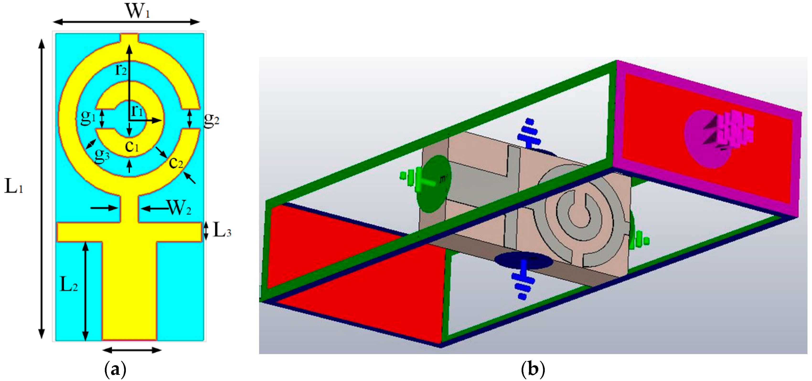
The design of the UWB antenna starts with the designing of a metamaterial unit cell. The primary target is to determine a unit cell having resonance properties in between the frequency range of 3.1 to 10.6 GHz. Numerous methods are used to design metamaterial structure, including split ring resonators (SRRs) [24,25]. The authors choose the most popular SSR structure for developing the unit cell. The structure of SRR contains two loops, where smaller loops belongs to a bigger loop, and opposite ends are slotted [24]. The magnetically resonant SRR structure produces a vertical magnetic field that is responsible for creating negative permeability. The controls of resonant behavior of the unit cell are attained using splits to the ring that familiarize capacitance. The metamaterial, which shows both negative permeability and permittivity concurrently, are named double-negative (DNG) metamaterials. They can also be single-negative materials, like epsilon-negative (ENG) or mu-negative (MNG). The metamaterial that has double- or single-negative properties can attain better performance in numerous essential applications, such as polarization rotators, invisibility cloaking, SAR reduction, and many more. Figure 1a represents the proposed unit cell of rectangular SSR. Figure 1b shows the simulation geometry of the unit cell in Computer Simulation Technology (CST) simulation software [42]. The structure is printed on a low-cost FR4 substrate which dielectric constant of 4.6 and height of 1.6 mm, to achieve the resonance of the unit cell within 3.1–10.6 GHz, and two capacitive loaded strips (CLSs) are accumulated for the modification of the SSR unit cell. Here, I-shaped strip line impersonator as extended metallic line, and CLS, act as electric dipoles [43]. The concurrent electric and magnetic resonance among the SRR is possible, due to the implementation of a combined structure that allows creating a vertical magnetic field, and CLS resonates over an equivalent electric field [44]. The design specification of the unit cell is summarized in Table 1.
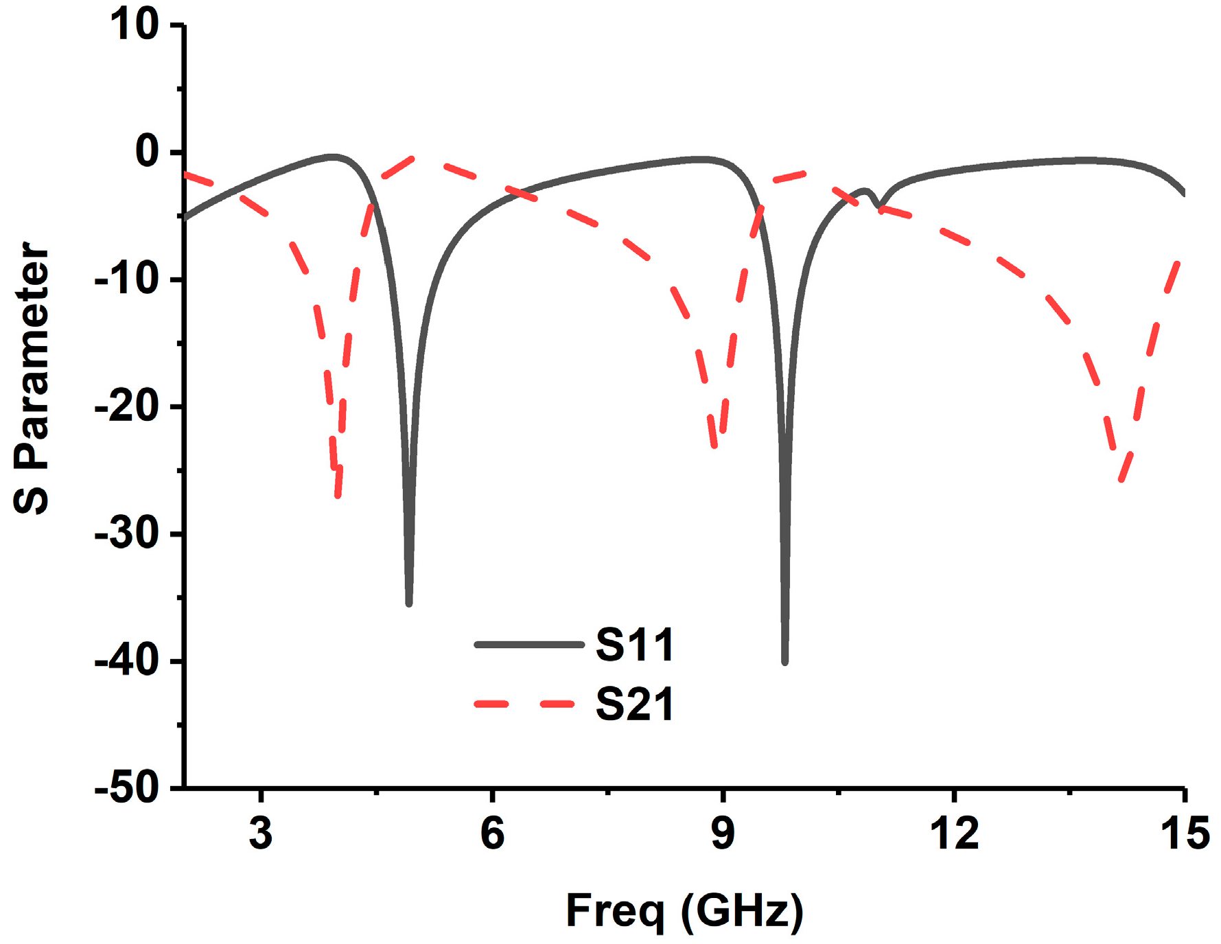
The simulation of the metamaterial unit cell is carried out using Computer Simulation Technology (CST) software based on the finite-difference time domain (FDTD). The S-parameters are observed from the simulation results. Figure 1b represents the simulation setup. The unit cell is located inside two waveguide ports on both sides of the x-axis, and the electromagnetic wave is excited along this axis. Along the walls vertical to the y-axis, a perfect electrical boundary condition is applied, and the magnetic conducting boundary is applied through the z-axis. For the simulation, frequency domain solver is applied by applying normalized matched impedance of 50 Ω. The S parameters (both reflection and transmission coefficient) are presented in Figure 2. Multiple transmission peaks are observed at the left-handed band that occurs at 5.2 and 10 GHz. The proposed SRR structure magnetic resonance is better than the reported overlap and self-oriented SRRs [27]. The fundamental useful parameters are extracted from S21 and S11 using the Nicolson–Ross–Weir approach [28,45] that includes permeability μr, permittivity εr, and refractive index nr.
These following equations are accomplished separately, consistent with
where:
, angular frequency
slab thickness
speed of light
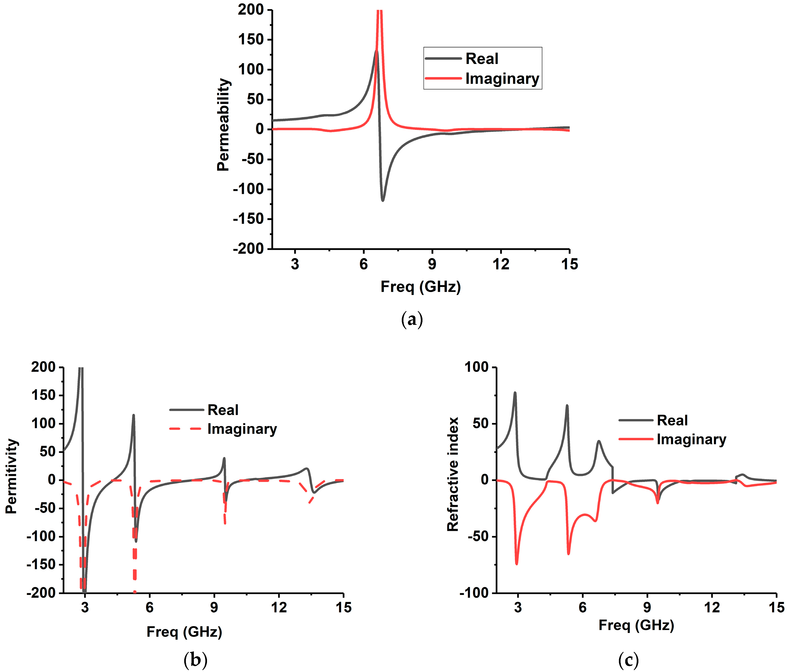
By following these Equations (1)–(5), all the effective parameters are calculated. The permeability, permittivity, and the refractive index are shown in Figure 3. The frequency covering the negative region is enlisted in Table 2. It is identified that the resonance frequencies from 5.30–7.90 GHz and 9.50–10.25 GHz, in both permeability and permittivity, are negative values, and then the structure can be listed in DNG metamaterial. The refractive indices are also initiated to be negative for the frequencies of 7.36–10.48 GHz and 12.85–13.15 GHz.
3. Antenna Sensor Design with MTM
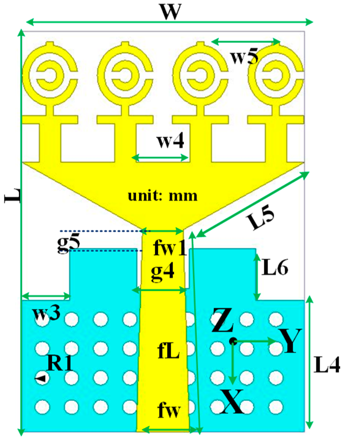
The schematic layout of the optimized MTM UWB antennas’ sensor design layout is displayed in Figure 4. The proposed design consists of a patch and ground plane, which is printed on 1.6 mm thick low-cost epoxy resin fiber FR4 substrate with dielectric constant 4.6. The UWB antenna patch is constructed with a feed line and a triangular strip patch. The four MTM identical unit cells are connected with the triangular copper strip along the y-axis. On the other hand, the partial ground plane is printed on the other side of the substrate with a rectangular and circular slot. To enhance the antenna performance, including impedance bandwidth, gain, and radiation, the MTM unit cell is used. A 50 Ω SMA connector is attached to the edge of the antenna to connect patch and ground plane. After optimization of the proposed antenna, the final design parameter is presented in Table 3.
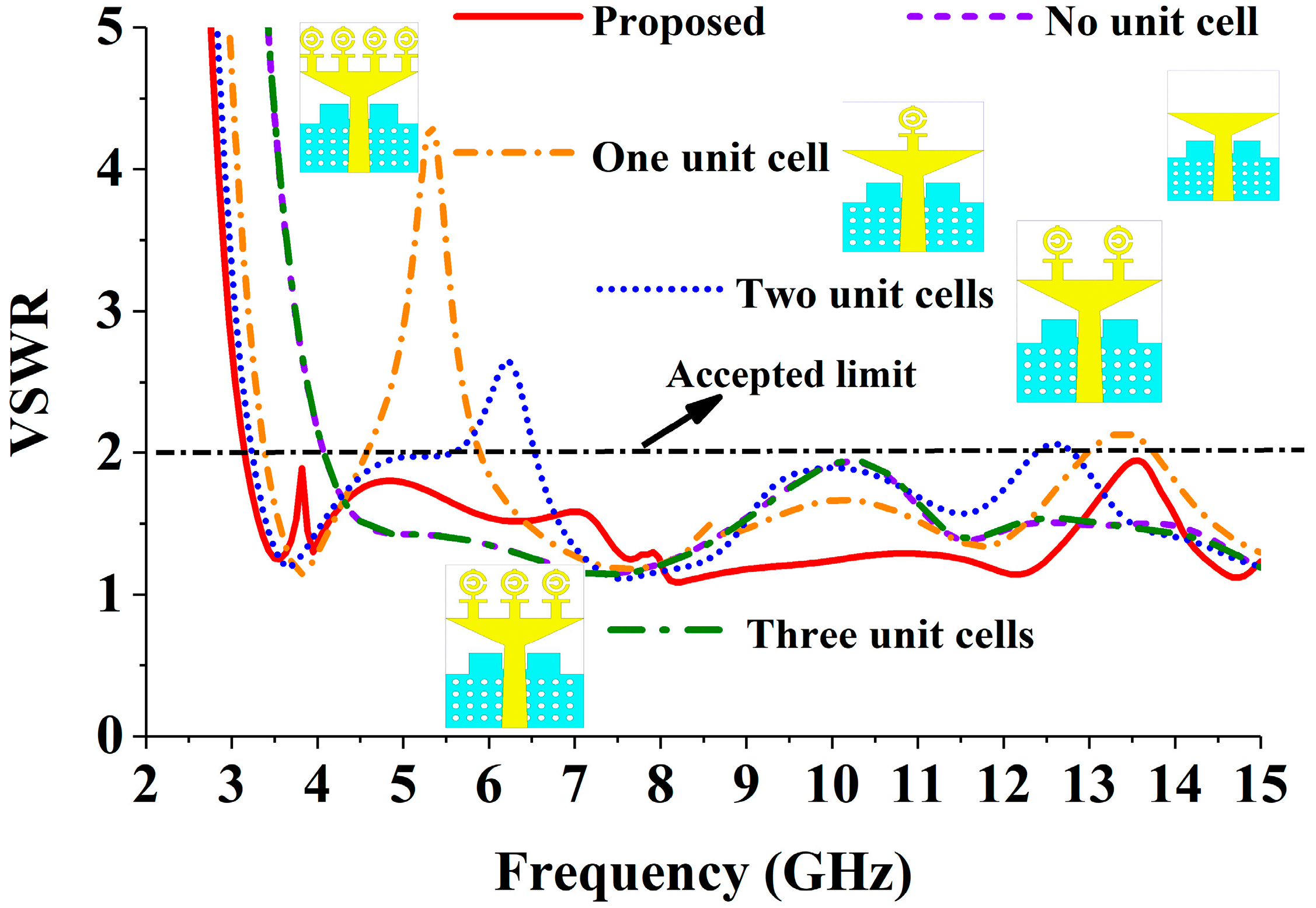
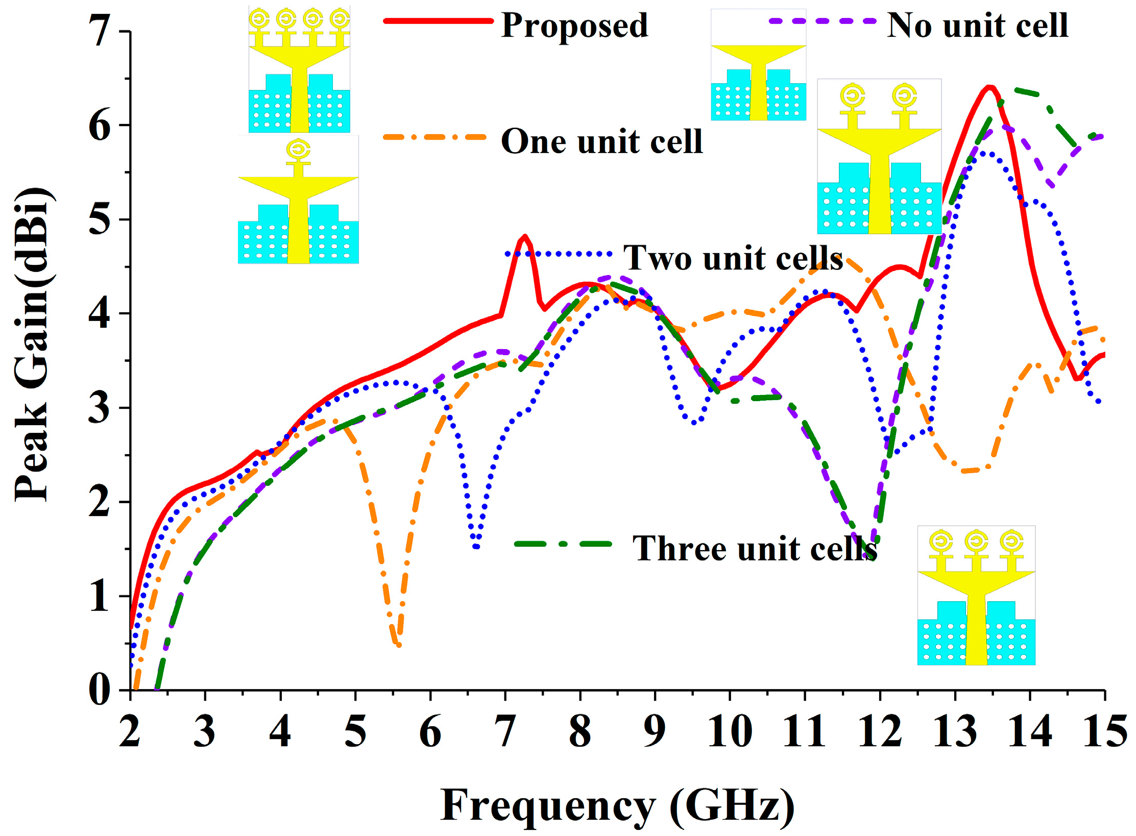
After inserting the MTM unit cell, the VSWR (Voltage Standing Wave Ratio) performance of the realized antenna is displayed in Figure 5. From this figure, it can be observed that without inserting the unit cell with the triangular strip and partial ground plane, the antenna achieves −10 dB impedance from 4.20 to 15 GHz, which does not cover the UWB frequency range (3.1–10.60 GHz) range. To shift the −10 dB resonance from 4.20 to 3.10 GHz, we have attached one, two, three, and four MTM unit cells with the triangular strip. The four-unit cell MTM antenna achieves the desired UWB frequency range regarding VSWR. The peak gain effect of the inserting MTM unit cell is also depicted in Figure 6. After attaching four identical MTM unit cells, the antenna achieved comparatively better gain across the desired UWB operating band.
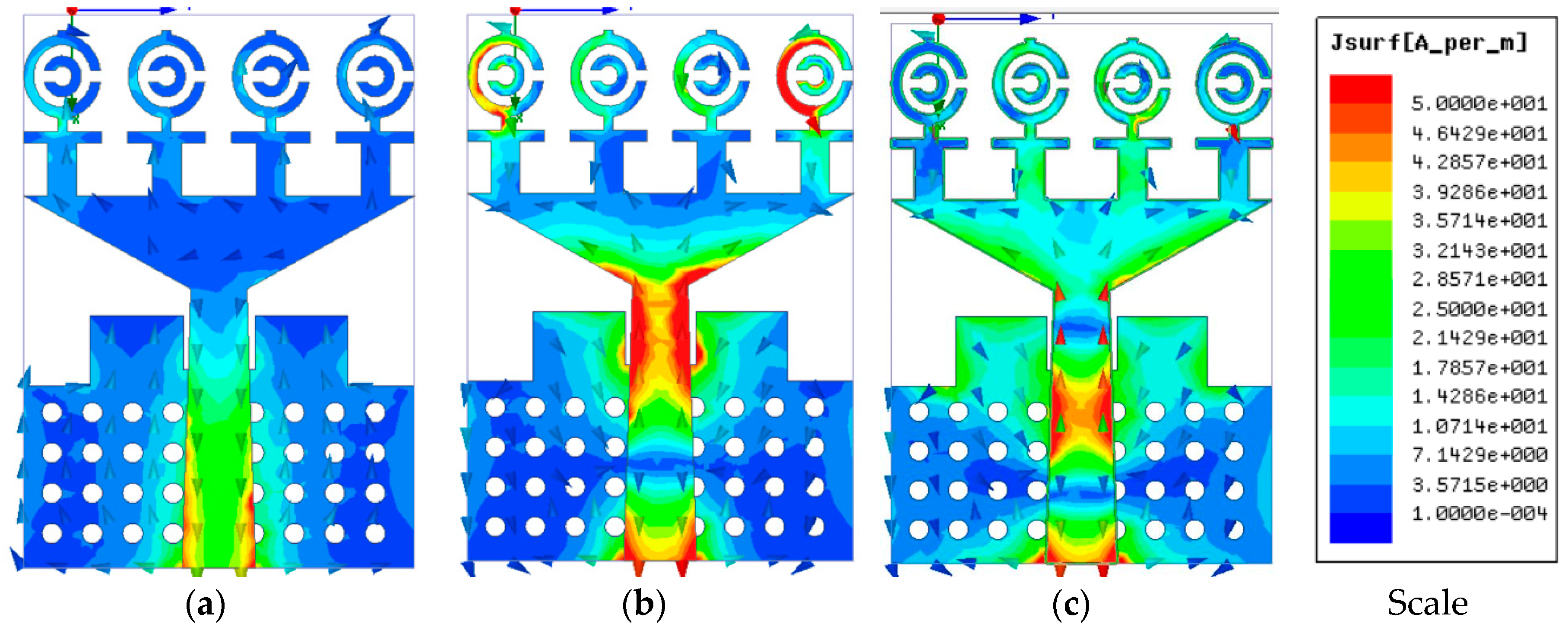
The magnitude and vector surface current distribution of the realized antenna is presented in Figure 7 at 3.25, 6.50, and 9.5 GHz. It can be observed that the current density flow dominates around the feed and triangular strip in the low-frequency band. On the other hand, the current flows density is dominant around the MTM unit cell with the fed and triangular strip, which plays an essential role in generating resonance and achieving UWB frequency band. At 6.50 GHz, the first and fourth MTM unit cell is greatly affected with the current flow, which ensures the UWB performance. On the other hand, at 9.50 GHz, the second and third unit cell with the triangular strip was excited more to achieve a wide bandwidth.
4. Antenna Sensor Performance Validation
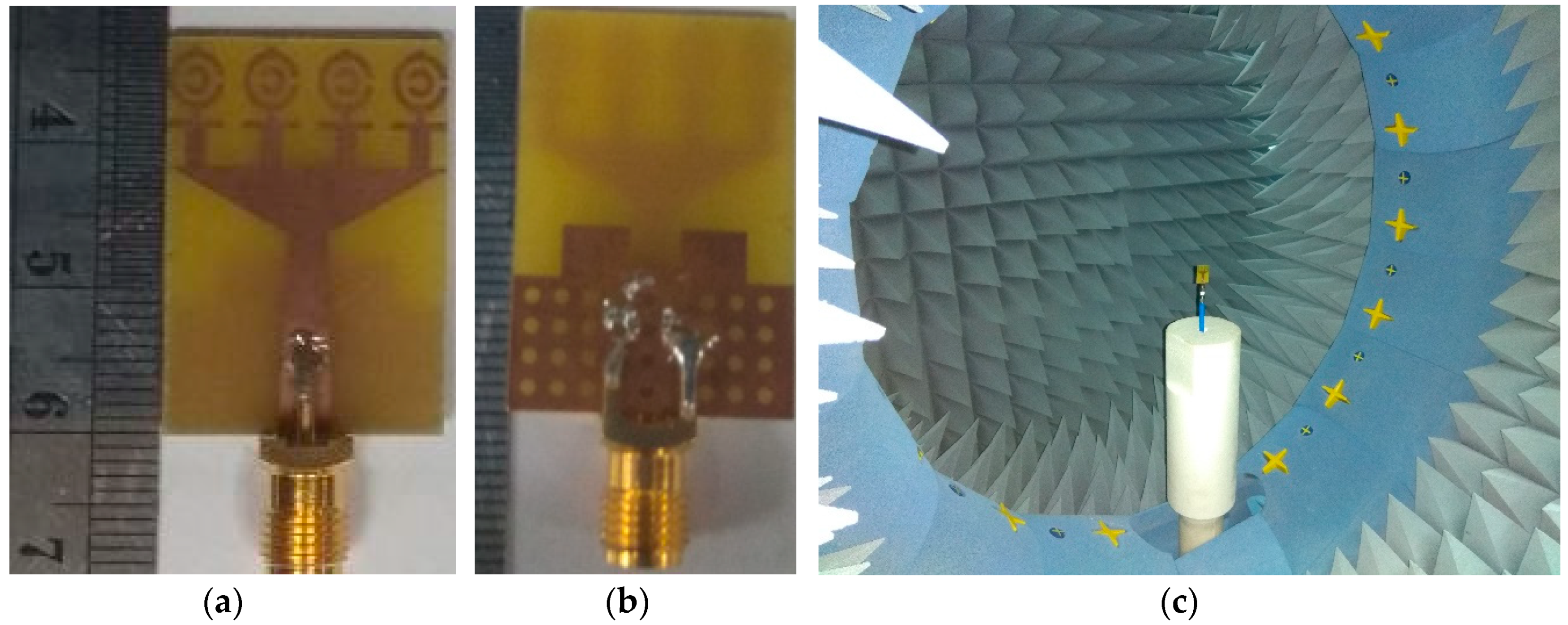
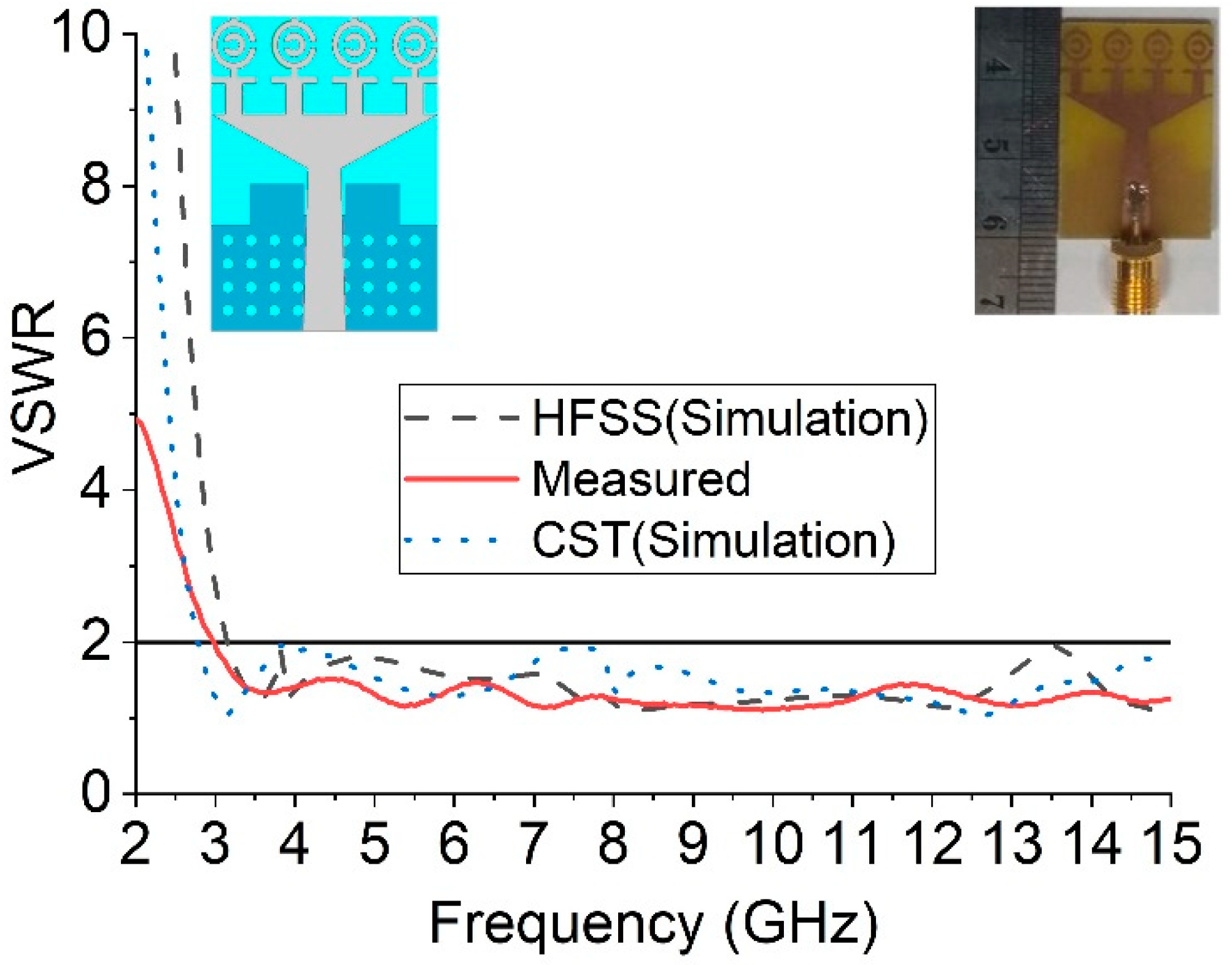
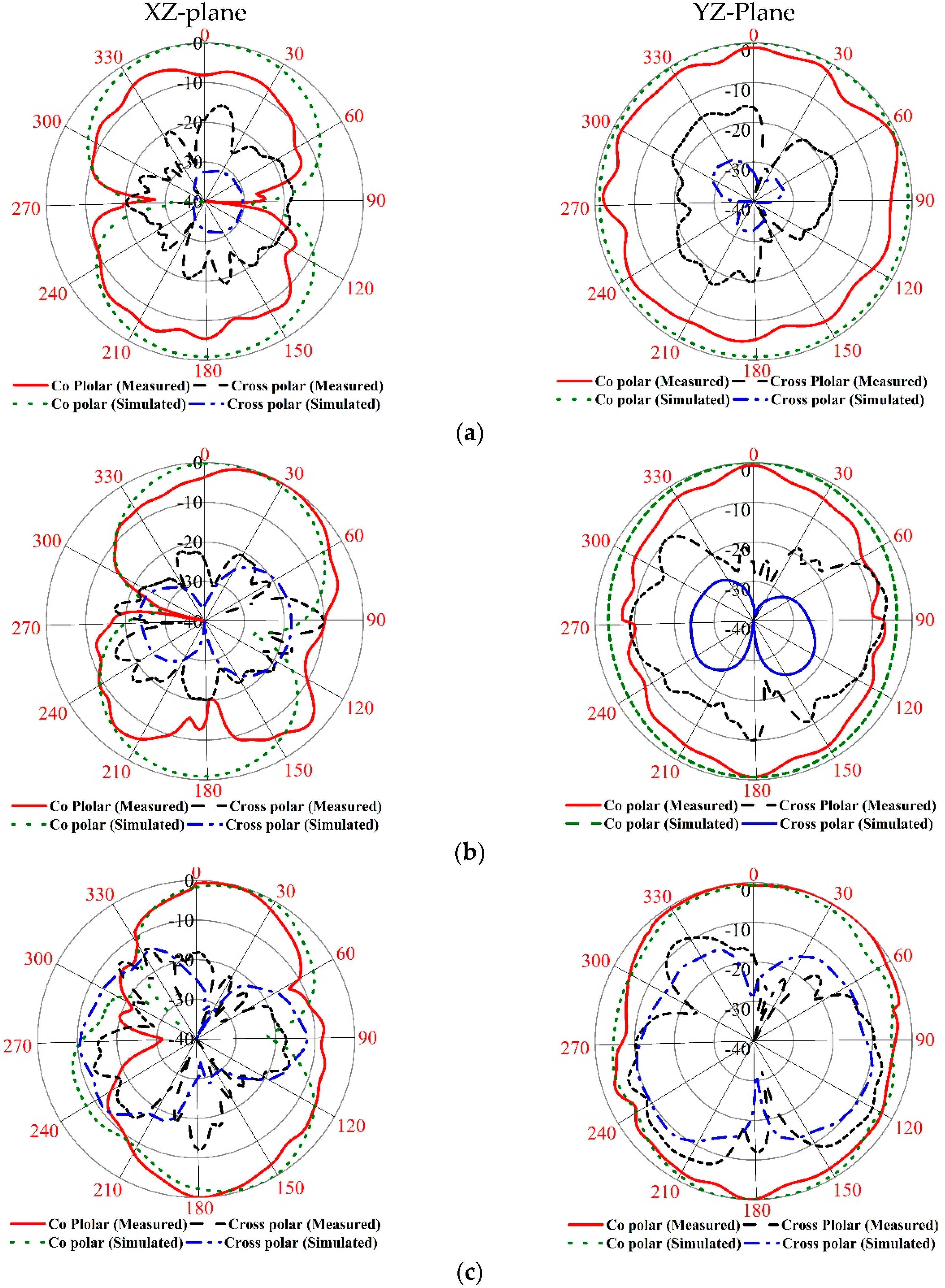
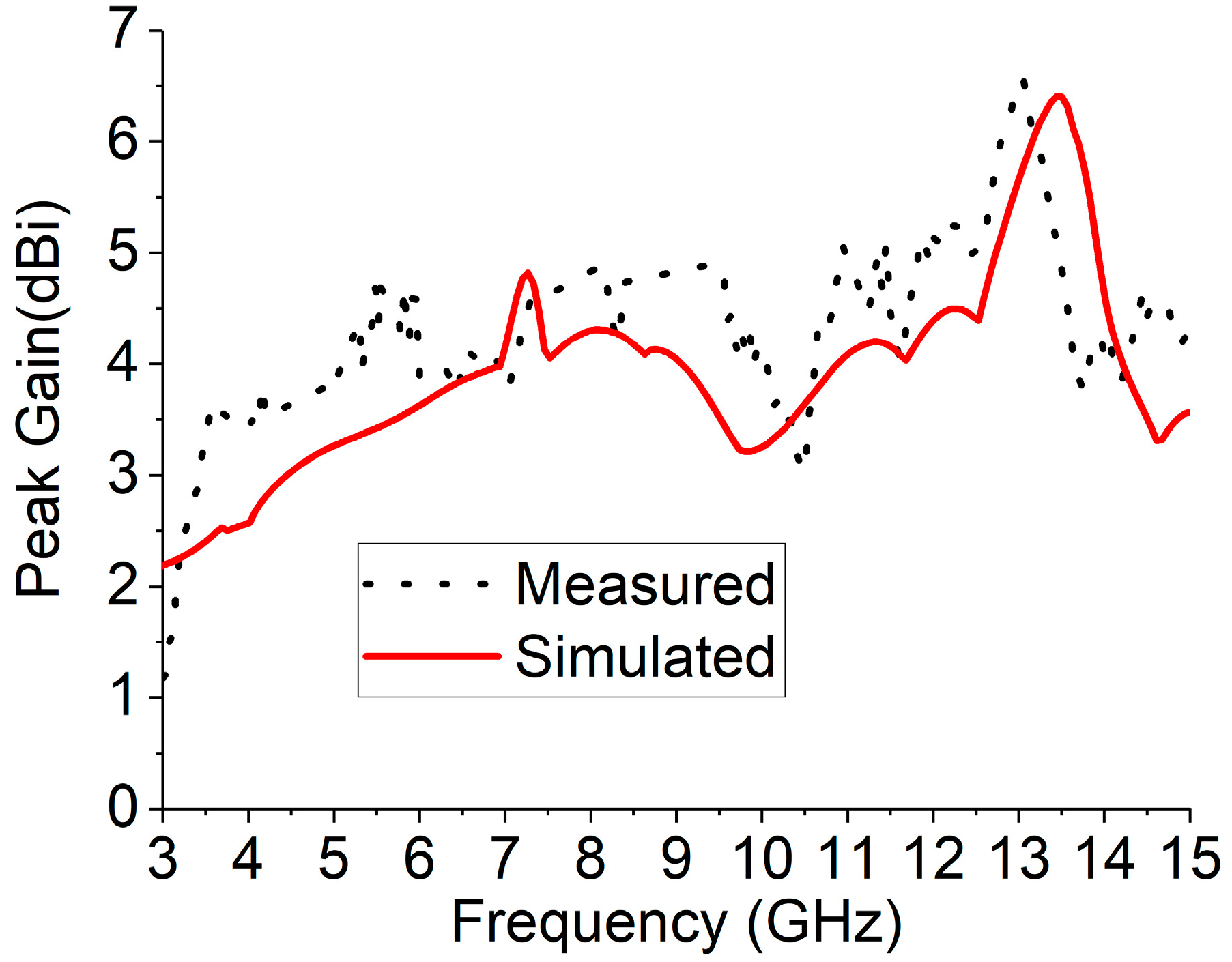
The numerical investigation has been performed in 3D electromagnetic simulator HFSS (High-Frequency Structure Simulator) and CST. After manual optimization of the realized antenna sensor dimension parameter through the simulation software, the design was fabricated in the UKM Lab-based PCB prototype machine LPKF. The fabricated prototype of the designed antenna is shown in Figure 8, top and bottom view. The VSWR was measured in UKM microwave lab using the N5227A (10–67 GHz) network analyzer. The far-field characteristics of the realized antenna were measured by Satimo near the field measurement facilities of the UKM microwave lab, which is shown in Figure 8c. The numerical and measured VSWR of the realized antenna is depicted in Figure 9. The numerical VSWR in HFSS less than 2 is about 3.10–15 GHz and 2.8–15 GHz in the CST simulation software. On the other hand, a measured VSWR was achieved from 2.97 to 15 GHz, which fully covered the UWB band. The simulated results significantly matched with the measured results. Figure 10 illustrated the simulated and measured 2D polar radiation pattern of the realized antenna (XZ plane and YZ plane) at 3.25, 6.50, and 9.5 GHz, respectively. The radiation pattern also displayed the co-polarization and cross-polarization results. It can be noted that the antenna exhibits a shape pattern as in Figure 8 in the XZ plane, and an omnidirectional pattern in the YZ plane, which is a dipole-like radiation pattern. The cross-polarization is comparatively low with respect to polarization. Figure 11 depicts the simulated and measured peak realized gain of the antenna. From this figure, it can be stated that the antenna achieves more than 3 dB peak gain across the desired operating band.
5. Microwave Imaging Setup with Multiple Receiver
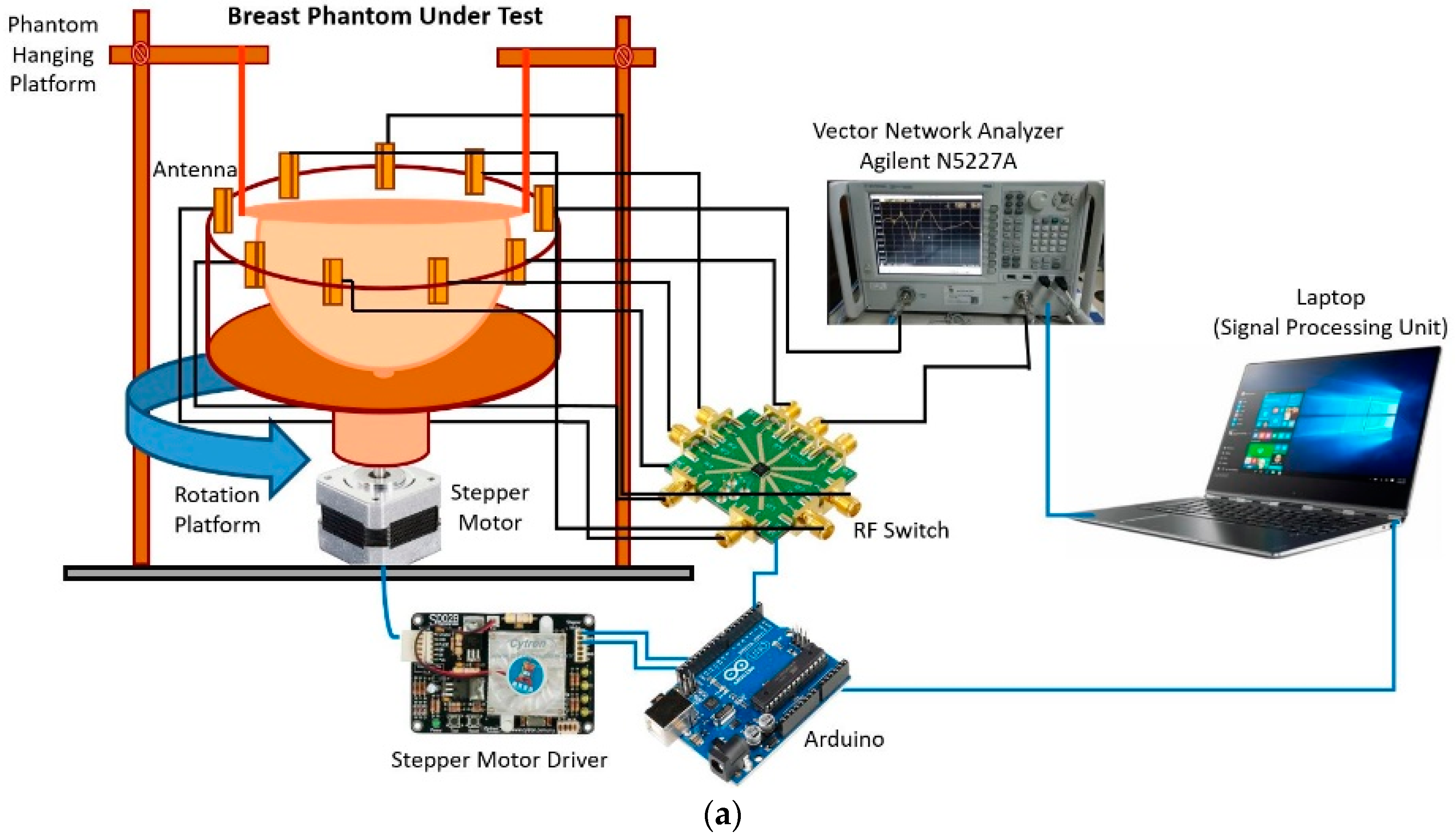
The breast imaging system is designed to evaluate the imaging performance of detecting breast tumor using a realistic lab-based breast phantom. The architecture and different component of the proposed experimental breast imaging system are depicted in Figure 12a. The proposed microwave imaging system consists of an antenna array, (9 antennas, one for transmitting and eight for receiving the ultrawideband signals), the stepper motor-based antenna mounting stand, the flexible phantom hanging platform, an RF switching system to control the receivers, and the personal computer-based signal processing and image reconstruction unit. The used antennas are mounted on an adjustable transparent plastic rotational table. The nine plastic sticks are installed on a rotating platform with an SD02B controlled stepper motor. The breast phantom is placed inside the antenna array using a hanging platform and scanned using the nine MTM-based UWB antenna array. The gap between the antenna and the phantom is maintained at 140 mm. The mechanical rotation platform can rotate the antenna array in polar coordinates from 0 to 2π around the breast phantom using the stepper motor. The antennas are connected to a GaAs MMIC SP8T (9 Port) non-reflective positive control switching network using low-loss coaxial cables. The received signal from all eight receivers is collected by switching the receiving antennas. The data (S21, S31, S41, S51, S61, S71, and S81) are collected at each 7.2°, and 50 equal points, covering the total 360°. The imaging system uses an Agilent E8358A vector network analyzer (VNA) microwave transceiver. The port 1 of VNA generates microwave signals through the transmitting antenna in the frequency domain, and transmits it to the breast phantom. The backscattered signal is received by the remaining eight antennas by another port via the SP8T RF switch, and sent to the image processing unit. All these devices and electromechanical circuits, related to the data acquisition process, are controlled by a PC-controlled Arduino Uno control circuit which is connected to the personal computer through the USB port. The VNA is also connected to the PC via a GPIB port, and data are received for further processing. The collected data are processed by a laptop using the DMAS imaging algorithm, which reconstructs the image of the breast interior to detect and localize a tumor object.
6. Phantom Fabrication with Imaging Setup
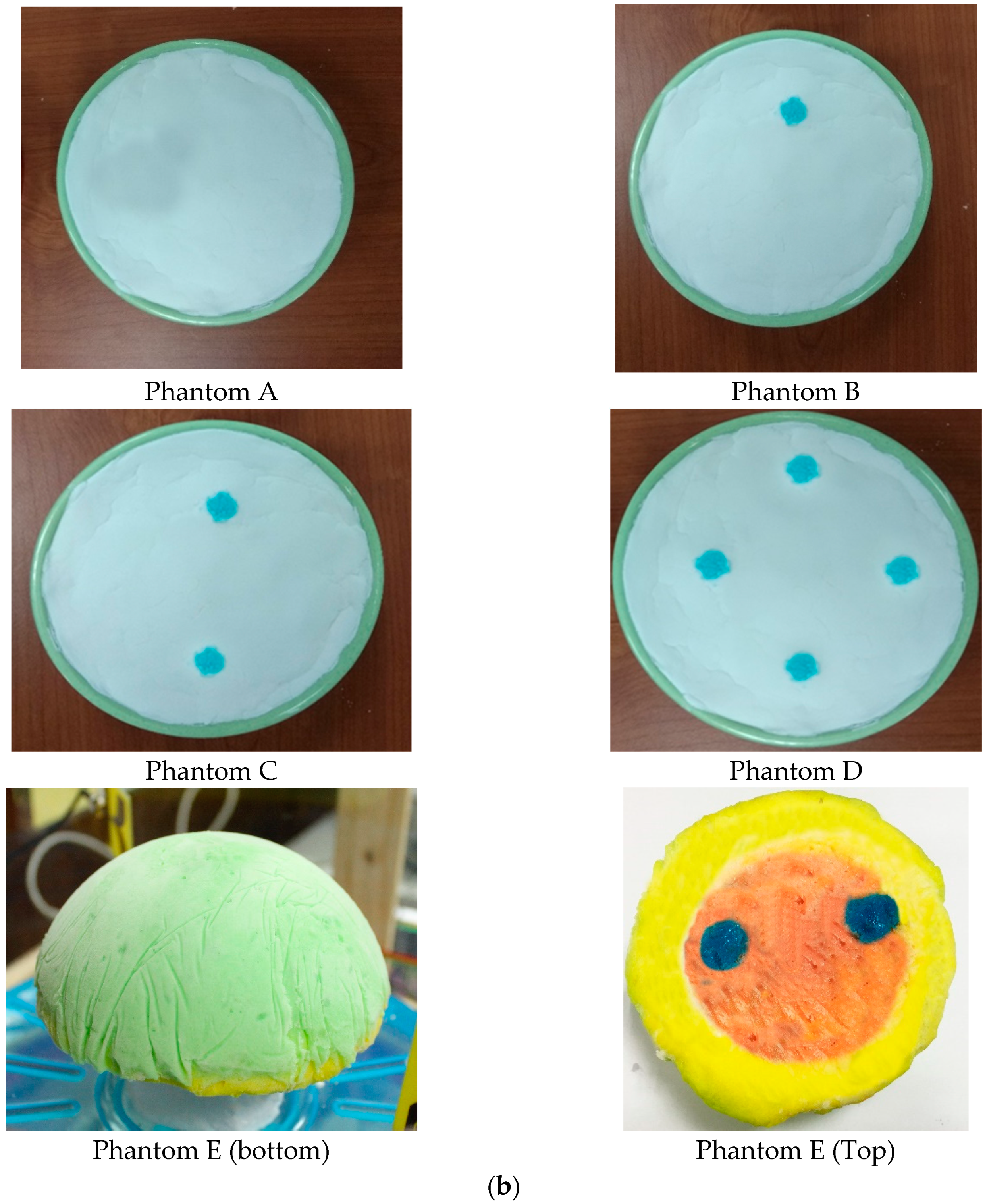
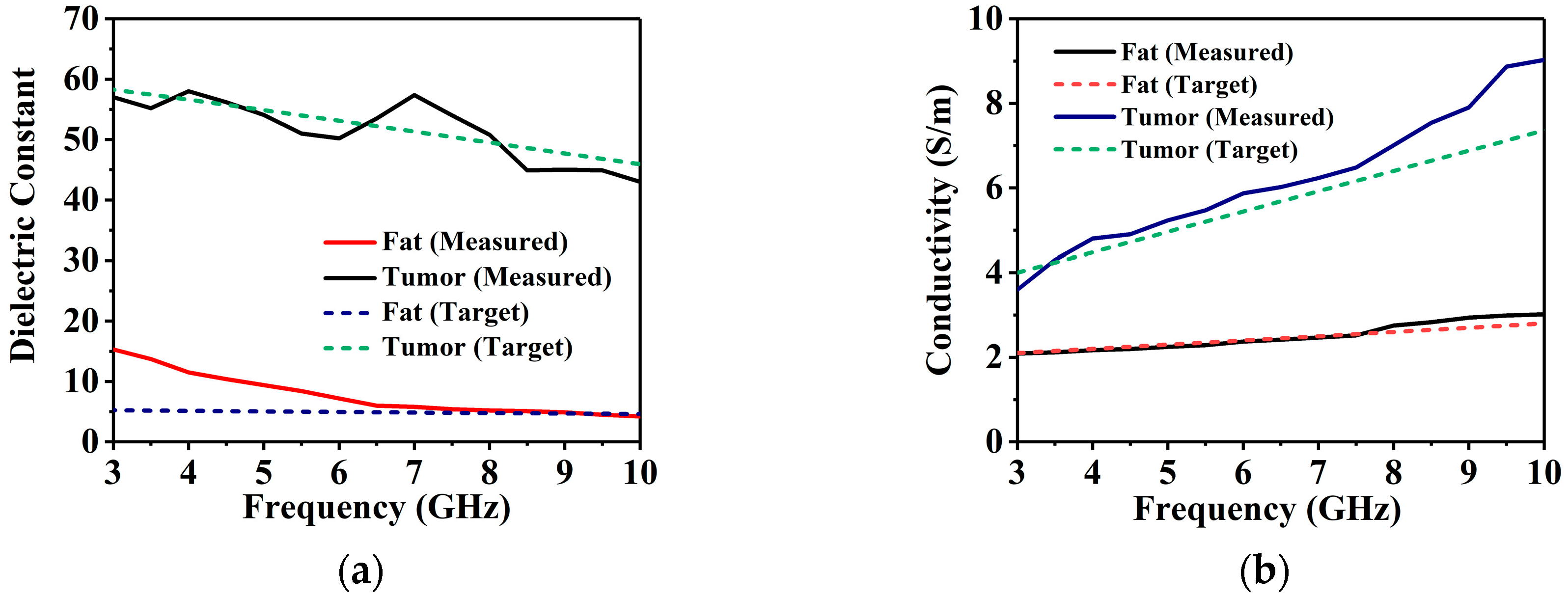
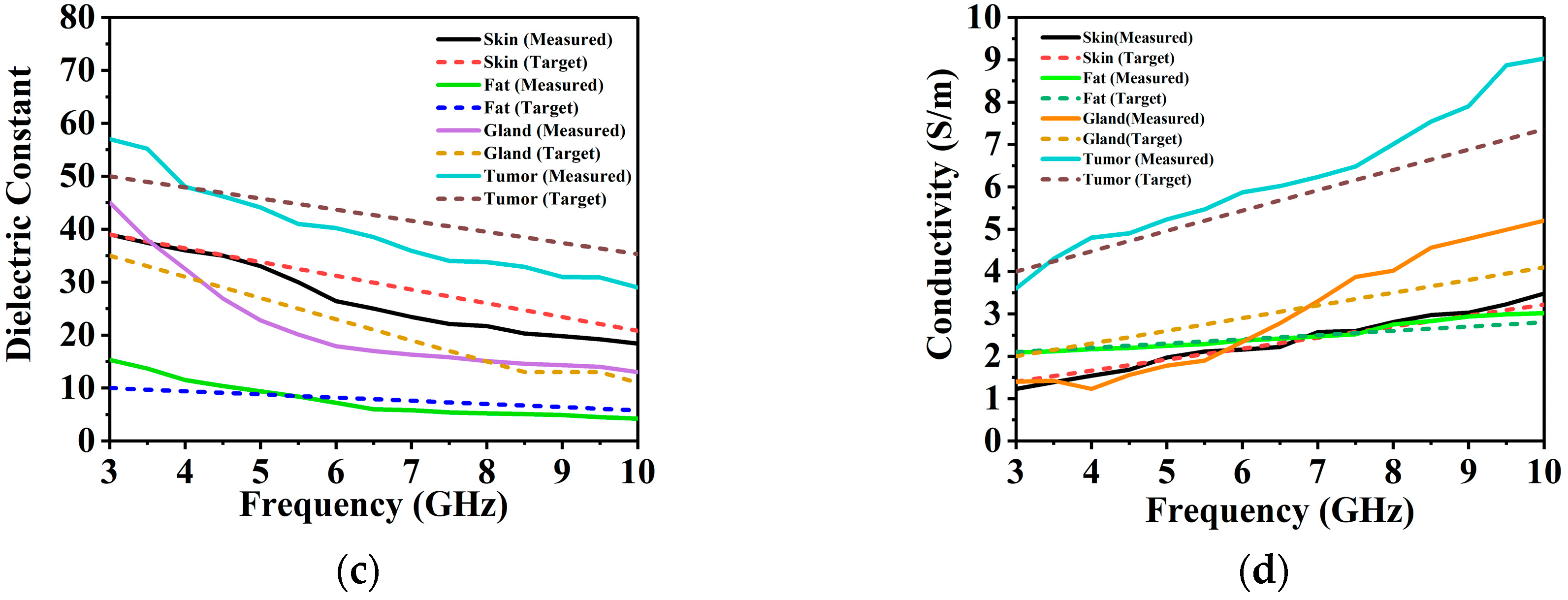
The lab-based breast phantom used for the imaging system are discussed in the phantom development and measurement procedure in [15]. The radii of the phantoms are 55 mm (phantoms A, B, and C) and 60 mm (phantom D and phantom E) which are displayed in Figure 12b. The tumor diameter and height are 10 mm and 40 mm, respectively. Holes were drilled manually in the appropriate positions of the phantoms, and the tumor material was poured in to form the tumors. This resulted in some tumors being placed at a slight offset. Four phantoms were constructed with a different tumor configuration. Phantom A is a homogeneous phantom without any tumors. It serves as the control test, that should appear blank due to the rotation subtraction method. Phantom B is constructed by adding a tumor 25 mm away from the center of the structure. This will be the primary test where the imaging system has to detect only a single target. Usually, DAS-based methods excel in such situations, as reflections off only one target have to be considered. A more challenging phantom C is created by replicating phantom B and adding another tumor on the opposite side of the center at an approximately equal distance. The presence of multiple targets can cause numerous internal reflections to misguide the imaging system. Thus, DMAS is utilized in the proposed system as it rewards higher coherence by multiplying individual pairs of delayed signals and adding them together as a form of coherence measurement. This quantity is used to scale the results obtained from the conventional DAS. Finally, Phantom D is constructed slightly larger at a radius of 60 mm as it is intended for a four-tumor objects. The tumor objects are also placed slightly further apart, at 35 mm at 90-degree intervals around the center, to maintain the structural integrity of the phantom. Mapping four different targets is usually not attempted or presented in most examples in the literature, as it is often difficult for DAS-based techniques, which were developed mostly as single target detection methods. A more realistic heterogenous phantom with four layers (skin, fat, gland, and tumor) is presented as phantom E in Figure 12b, which has more human-like dielectric properties and construction. Figure 13 represents the measured and targeted dielectric constant and electrical conductivity of each material of the phantoms against frequency. The dielectric constant and conductivity of homogenous phantom in Figure 13a,b is identical with the targeted curves. In addition, the properties of each material (skin, fat, gland, and tumor) of heterogenous phantom shown in Figure 13c,d demonstrates the accurate measurement properties with the targeted values. Therefore, the results of the phantom properties in this paper have the more realistic characteristics of the real human breast to be tested with the microwave imaging system efficiency. After developing and measuring the breast phantom, it is placed inside the antenna array, and the attenuation and reflection of breast tissues are considered on the performance of antennas, which is shown in Figure 14. The VNA parameters are set as IF (intermediate frequency) bandwidth 100 Hz, 10 dBm output power, and 3.0 to 8 GHz frequency range with 201 discrete points. The transmitting antenna transmits the microwave pulse towards the breast phantom, and the receiving eight antennas receive the scattering signals reflected from the phantom after every 7.2 degrees. To reduce air interference, the entire system is calibrated over the operating frequency using SOLT (Short-Open-Load-Thru) calibration (3.5 mm Agilent 85052 D) kit. The losses and permittivity of water are much higher than air, and real breast tissues, which create higher attenuation and reflection in the air–skin interface, are considered as the experimental method.
7. Imaging Results Analysis and Discussions
After capturing the backscattered signal through the developed imaging system, the data were processed to identify the breast phantom tumor object. By using the developed experimental setup, the complex frequency domain S-parameter data are captured, where m = 1, 2, …, M, and n = 1, 2 …, N represent the angular positions of each rotation. The reflected parameter mostly presents the shallow depths under the skin layer, as signals are bounced off the opposite side of the breast phantom have to travel through the phantom twice, and are significantly attenuated. Thus, antennas with very low inherent return loss are ideal for detecting weak reflected signals. Methods to remove the reflections from the skin are critical for detecting scattered signals from inside the phantom, since reflection from the air–skin interface is orders of magnitude stronger than reflections from the tumors. Several techniques, like matching liquids [46] and rotation subtraction [47], have been employed. Matching liquids have dielectric properties, like skin, thus allowing maximum power coupling to the phantom’s internal structure. Such designs require antennas that can operate when immersed in the matching liquid. However, matching liquid causes uncomfortable breast compression during measurements, and increases the overall weight and complexity of the system. Rotation subtraction relies on a comparison between an original illumination and at least one rotated illumination [48]. In such systems, the antenna array is placed around the region of interest. Once the data are recorded for the original illumination, the array is rotated around the phantom to get offset data.
In this study, the Γ(φn, fm) is separated into two matrices by n being odd and even, or Γodd(φl, fm) and Γeven(φl, fm), respectively, where l = 1, 2, …, N/2. Thus, Γodd(φl, fm) can be considered original illumination, and Γeven(φl, fm) is the ‘offset’ illumination of the first matrix. Finally, rotation subtraction is implemented by just calculating the difference between the two matrices.
Γ(φl, fm) = Γodd(φl, fm) − Γeven(φl, fm)
Fourier transform is used to convert the reflection coefficient from frequency domain to time domain for each antenna.
where
and
Here, ωm denotes the angular velocity and k indicates the equal distant points.
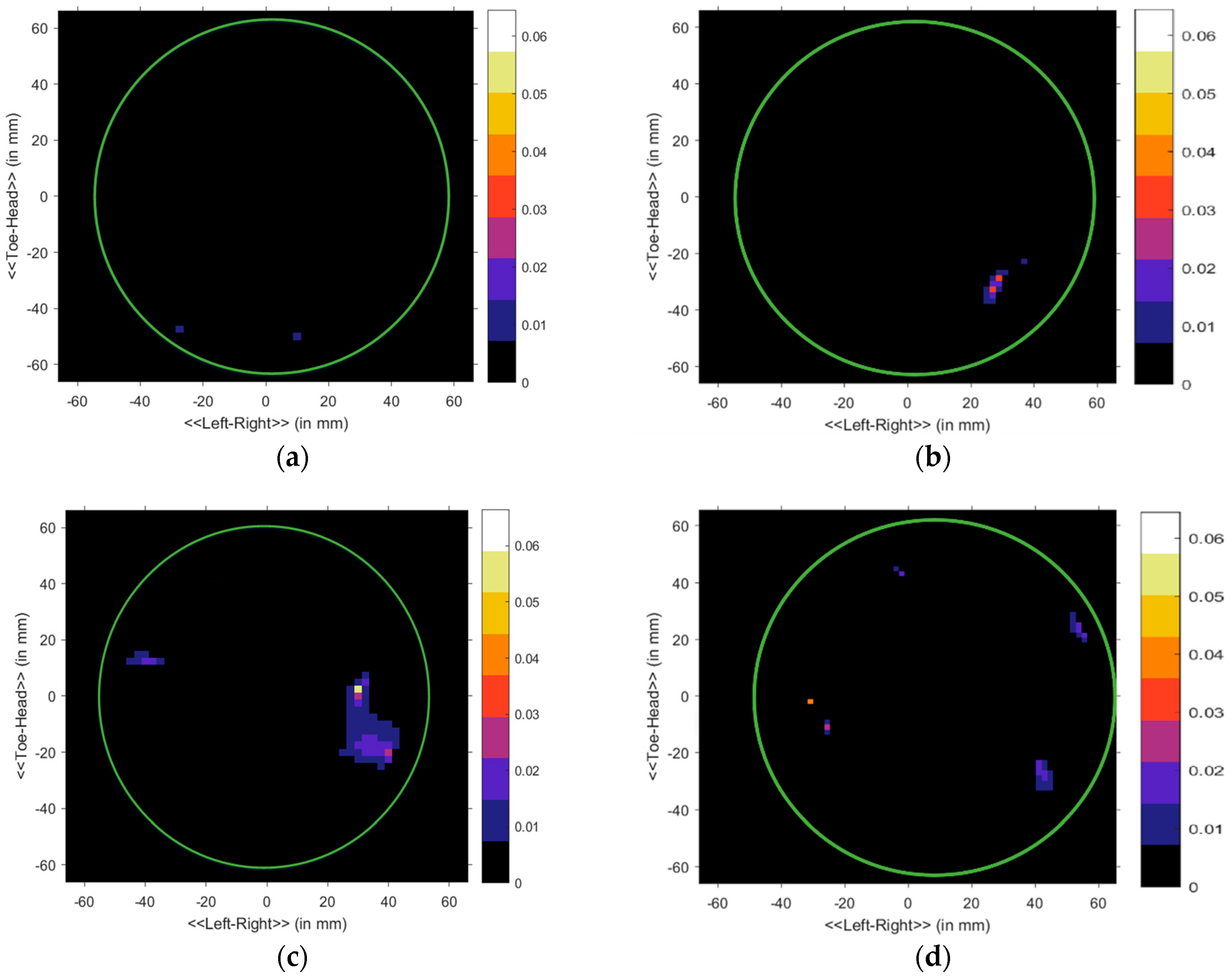
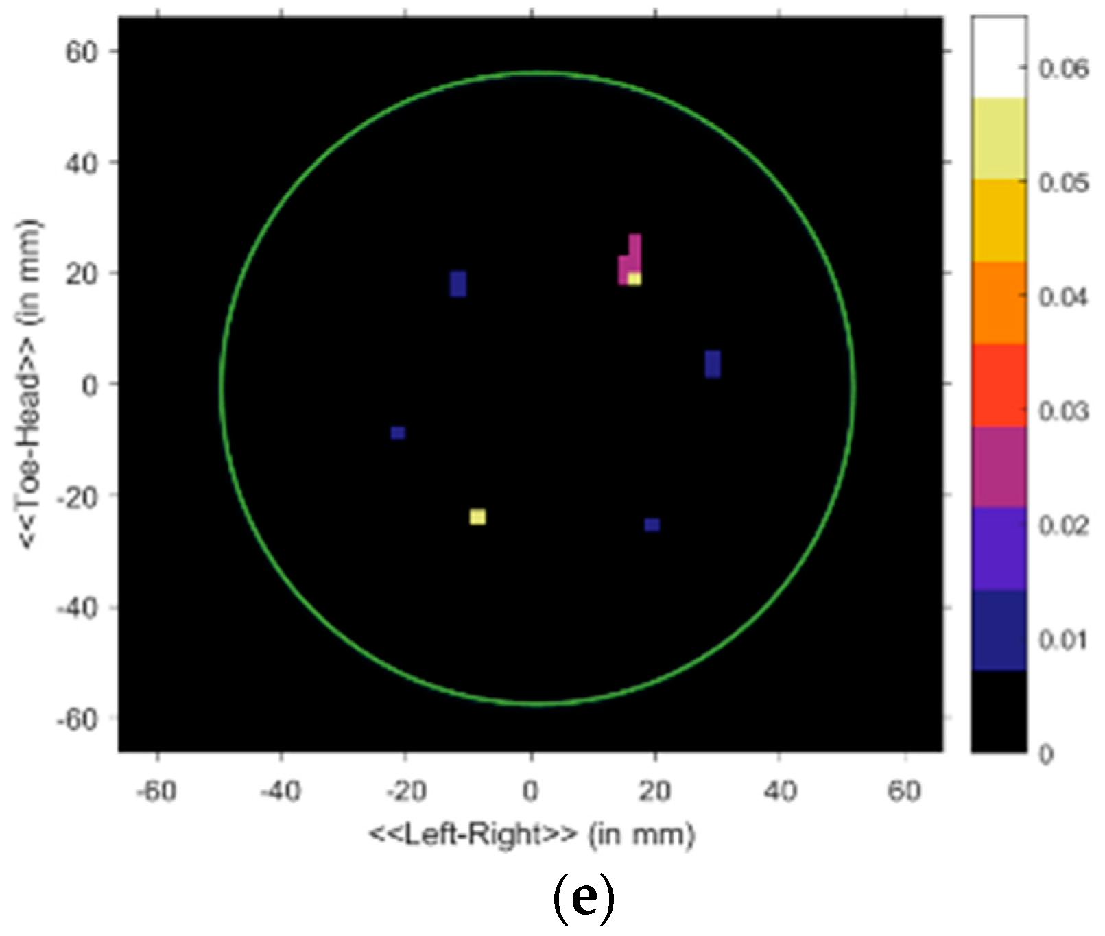
Subsequently, the data in the S matrix was processed using the delay-multiply-and-sum (DMAS) algorithm for the precise reconstruction of the image [49]. The pictures of the developed breast phantoms with tumor are shown in Figure 15. We are using cylindrically symmetric homogeneous and heterogeneous phantom (excluding the tumors), and the phantom is placed at the center of the rotation axis. Thus, the skin reflections are nearly identical for all observations, and any discrepancies between the even and odd sets must be due to scattered signals from the internal structure of the phantom. A continuous green circle is drawn on the final imaging results to indicate the phantom surface, which is shown in Figure 15. Figure 15a is mostly blank as expected, due to the homogeneity of phantom A. Small insignificant specks of noise appear at the surface of phantom A, possibly due to cracks on its exterior. Figure 15b shows a single point of high contrast to the fat material as white, along with some lower intensity clutter below it. The high contrast location is recognized as the center of the tumor, and the clutter can be attributed to imperfect insertion of tumor, resulting in minor cracks in the fat being filled with tumor material. Figure 15c clearly shows two separate clutters, indicating the presence of two tumors. However, the upper tumor in Figure 15c is slightly closer to the center than the lower tumor. Upon re-examination of phantom C, it was noted that one tumor was placed closer. The discrepancy can be observed in Figure 15c. Finally, Figure 15d shows one high contrast clutter, most likely caused by the tumor nearest to the skin. The other three tumors also appear, but only as low contrast clusters. Since they are buried more in-depth, the reflected signals face more attenuation, resulting in less contrast. However, the presence of four distinct clutters indicates the detection of all four tumors. Figure 15e depicts the imaging results of the heterogeneous phantom with two tumor objects, which is shown in 12b. From this imaging picture, it can be noted that two tumors like object have detected with some other object, due to the different layers. Table 4 represents the comparison of the different imaging system with proposed system regarding the antenna, the number of an element, the number of scanning position, static or fixed antennas, measurement of time or frequency domain, and method of imaging algorithm. Initially, our system emphasizes the compact lab-based antenna design and nine-antenna array-based imaging system developed for testing the lab-based breast phantom (homogeneous and heterogeneous), with and without tumor condition, through the MATLAB-based DMAS imaging algorithm. Good imaging results have achieved from the system, which are highly desirable for performing nondestructive biomedical detections.
8. Conclusions
A microwave system for breast tumor imaging is presented in this article. The designed imaging system comprises an array of nine metamaterial loaded antennas sensor that can work across the UWB band. Simulation and measured results of this proposed antenna demonstrate the operating bandwidth of 2.97 to 15 GHz with reflection coefficient <−10 dB, and stable peak gain across the operating band. The proposed antenna displays a stable omnidirectional radiation pattern which is the primary requirement for microwave imaging. A suitable SP8T device is used to enable the eight receiver antennas to 50 rotated position, to send reflected microwave signals, whereas the reflected backscattered signals were recorded PNA (Performance Network Analyzer) using the MATLAB-based software architecture. Several lab-based breast phantoms that match the dielectric properties of real breast tissues with breast tumor were fabricated and measured to test the validity of the imaging system. After collecting the data, a post-processing DMAS algorithm was used to significantly detect the breast tumor existence and location inside the developed phantom. Successful images have been presented, which recognize a single tumor object or multiple tumor objects, identified using the measured data by the developed imaging system.
Author Contributions
M.S. and M.T.I. (Md. Tarikul Islam) made substantial contributions to conception, design, and analysis. S.K. provided necessary instructions for experimental purpose. M.T.I. (Mohammad Tariqul Islam) participated in revising the article critically for important intellectual contents.
Funding
This work was supported by the UKM under grant No. MI-2017-001.
Conflicts of Interest
The authors declare no conflict of interest.
References
- Santorelli, A.; Porter, E.; Kirshin, E.; Liu, Y.J.; Popovic, M. Investigation of classifiers for tumor detection with an experimental time-domain breast screening system. Prog. Electromagn. Res. 2014, 144, 45–57. [Google Scholar] [CrossRef]
- Christodoulou, C.; Railton, C.J.; Klemm, M.; Gibbins, D.; Craddock, I.J. Analysis of a UWB Hemispherical Antenna Array in FDTD With a Time Domain Huygens Method. IEEE Trans. Antennas Propag. 2012, 60, 5251–5258. [Google Scholar] [CrossRef]
- Yifan, W.; Abbosh, A.M.; Henin, B.; Phong Thanh, N. Synthetic Bandwidth Radar for Ultra-Wideband Microwave Imaging Systems. IEEE Trans. Antennas Propag. 2014, 62, 698–705. [Google Scholar] [Green Version]
- Amineh, R.K.; Ravan, M.; Trehan, A.; Nikolova, N.K. Near-Field Microwave Imaging Based on Aperture Raster Scanning With TEM Horn Antennas. IEEE Trans. Antennas Propag. 2011, 59, 928–940. [Google Scholar] [CrossRef]
- Unal, I.; Turetken, B.; Canbay, C. Spherical Conformal Bow-Tie Antenna for Ultra-Wide Band Microwave Imaging of Breast Cancer Tumor. Appl. Comput. Electromagn. J. 2014, 29, 124–133. [Google Scholar]
- Fear, E.C.; Li, X.; Hagness, S.C.; Stuchly, M.A. Confocal microwave imaging for breast cancer detection: Localization of tumors in three dimensions. IEEE Trans. Biomed. Eng. 2002, 49, 812–822. [Google Scholar] [CrossRef]
- Scapaticci, R.; Catapano, I.; Crocco, L. Wavelet-based adaptive multiresolution inversion for quantitative microwave imaging of breast tissues. IEEE Trans. Antennas Propag. 2012, 60, 3717–3726. [Google Scholar] [CrossRef]
- Abbosh, A.; Crozier, S. Strain imaging of the breast by compression microwave imaging. IEEE Antennas Wirel. Propag. Lett. 2010, 9, 1229–1232. [Google Scholar] [CrossRef]
- Geffrin, J.-M.; Sabouroux, P.; Eyraud, C. Free space experimental scattering database continuation: Experimental set-up and measurement precision. Inverse Probl. 2005, 21, S117. [Google Scholar] [CrossRef]
- Shao, W.; Edalati, A.; McCollough, T.R.; McCollough, W.J. A Time-Domain Measurement System for UWB Microwave Imaging. IEEE Trans. Microw. Theory Tech. 2018, 66, 2265–2275. [Google Scholar] [CrossRef]
- Zhang, J.; Fear, E.C.; Johnston, R.H. Cross-Vivaldi antenna for breast tumor detection. Microw. Opt. Technol. Lett. 2009, 51, 275–280. [Google Scholar] [CrossRef]
- Abbak, M.; Akıncı, M.; Çayören, M.; Akduman, I. Experimental microwave imaging with a novel corrugated Vivaldi antenna. IEEE Trans. Antennas Propag. 2017, 65, 3302–3307. [Google Scholar] [CrossRef]
- Salvador, S.M.; Fear, E.C.; Okoniewski, M.; Matyas, J.R. Exploring joint tissues with microwave imaging. IEEE Trans. Microw. Theory Tech. 2010, 58, 2307–2313. [Google Scholar] [CrossRef]
- Beada’a, J.M.; Abbosh, A.M.; Mustafa, S.; Ireland, D. Microwave system for head imaging. IEEE Trans. Instrum. Meas. 2014, 63, 117–123. [Google Scholar]
- Islam, M.; Samsuzzaman, M.; Islam, M.; Kibria, S.; Singh, M. A Homogeneous Breast Phantom Measurement System with an Improved Modified Microwave Imaging Antenna Sensor. Sensors 2018, 18, 2962. [Google Scholar] [CrossRef] [PubMed]
- Porter, E.; Bahrami, H.; Santorelli, A.; Gosselin, B.; Rusch, L.A.; Popović, M. A wearable microwave antenna array for time-domain breast tumor screening. IEEE Trans. Med. Imaging 2016, 35, 1501–1509. [Google Scholar] [CrossRef]
- Islam, M.M.; Islam, M.T.; Faruque, M.R.I.; Samsuzzaman, M.; Misran, N.; Arshad, H. Microwave imaging sensor using compact metamaterial UWB antenna with a high correlation factor. Materials 2015, 8, 4631–4651. [Google Scholar] [CrossRef]
- Sugitani, T.; Kubota, S.; Toya, A.X.X.; Kikkawa, T. A Compact 4x4 Planar UWB Antenna Array for 3-D Breast Cancer Detection. IEEE Antennas Wirel. Propag. Lett. 2013, 12, 733–736. [Google Scholar] [CrossRef]
- Foroutan, F.; Nikolova, N.K. Active Sensor for Microwave Tissue Imaging with Bias-Switched Arrays. Sensors 2018, 18, 1447. [Google Scholar] [CrossRef]
- Jafari, H.; Deen, J.; Hranilovic, S.; Nikolova, N. Co-polarised and cross-polarised antenna arrays for breast, cancer detection. IET Microw. Antennas Propag. 2007, 1, 1055–1058. [Google Scholar] [CrossRef]
- Porter, E.; Kirshin, E.; Santorelli, A.; Coates, M.; Popovic, M. Time-domain multistatic radar system for microwave breast screening. IEEE Antennas Wirel. Propag. Lett. 2013, 12, 229–232. [Google Scholar] [CrossRef]
- Woten, D.A.; El-Shenawee, M. Broadband dual linear polarized antenna for statistical detection of breast cancer. IEEE Trans. Antennas Propag. 2008, 56, 3576–3580. [Google Scholar] [CrossRef]
- Veselago, V.G. The Electrodynamics of substances with simultaneously negative values of ϵ and μ. Physics-Uspekhi 1968, 10, 509–514. [Google Scholar] [CrossRef]
- Pendry, J.B.; Holden, A.J.; Robbins, D.; Stewart, W. Magnetism from conductors and enhanced nonlinear phenomena. IEEE Trans. Microw. Theory Tech. 1999, 47, 2075–2084. [Google Scholar] [CrossRef] [Green Version]
- Smith, D.R.; Padilla, W.J.; Vier, D.; Nemat-Nasser, S.C.; Schultz, S. Composite medium with simultaneously negative permeability and permittivity. Phys. Rev. Lett. 2000, 84, 4184. [Google Scholar] [CrossRef] [PubMed]
- Alici, K.B.; Ozbay, E. A planar metamaterial: Polarization independent fishnet structure. Photonics Nanostruct. Fundam. Appl. 2008, 6, 102–107. [Google Scholar] [CrossRef] [Green Version]
- Shelby, R.A.; Smith, D.R.; Schultz, S. Experimental verification of a negative index of refraction. Science 2001, 292, 77–79. [Google Scholar] [CrossRef] [PubMed]
- Rusni, I.M.; Ismail, A.; Alhawari, A.R.H.; Hamidon, M.N.; Yusof, N.A. An aligned-gap and centered-gap rectangular multiple split ring resonator for dielectric sensing applications. Sensors 2014, 14, 13134–13148. [Google Scholar] [CrossRef] [PubMed]
- Eleftheriades, G.V.; Iyer, A.K.; Kremer, P.C. Planar negative refractive index media using periodically LC loaded transmission lines. IEEE Trans. Microw. Theory Tech. 2002, 50, 2702–2712. [Google Scholar] [CrossRef]
- Ekmekci, E.; Turhan-Sayan, G. Comparative investigation of resonance characteristics and electrical size of the double-sided SRR, BC-SRR and conventional SRR type metamaterials for varying substrate parameters. Prog. Electromagn. Res. B 2009, 12, 35–62. [Google Scholar] [CrossRef]
- Naeem, N.; Ismail, A.; Alhawari, A.R.H.; Mahdi, M.A. Subwavelength negative index planar terahertz metamaterial arrays using spiral split ring resonators for near field sensing. Int. J. Appl. Electromagn. Mech. 2015, 47, 827–836. [Google Scholar]
- Zhou, J.; Koschny, T.; Zhang, L.; Tuttle, G.; Soukoulis, C.M. Experimental demonstration of negative index of refraction. Appl. Phys. Lett. 2006, 88, 221103. [Google Scholar] [CrossRef] [Green Version]
- Huang, C.; Zhao, Z.; Feng, Q.; Cui, J.; Luo, X. Metamaterial composed of wire pairs exhibiting dual band negative refraction. Appl. Phys. B 2010, 98, 365–370. [Google Scholar] [CrossRef]
- Wang, J.; Qu, S.; Xu, Z.; Zhang, J.; Ma, H.; Yang, Y.; Gu, C. Broadband planar left-handed metamaterials using split-ring resonator pairs. Photonics Nanostruct. Fundam. Appl. 2009, 7, 108–113. [Google Scholar] [CrossRef]
- Zhou, X.; Liu, Y.; Zhao, X. Low losses left-handed materials with optimized electric and magnetic resonance. Appl. Phys. A 2010, 98, 643–649. [Google Scholar] [CrossRef]
- Wang, J.; Qu, S.; Zhang, J.; Ma, H.; Yang, Y.; Gu, C.; Wu, X.; Xu, Z. A tunable left-handed metamaterial based on modified broadside-coupled split-ring resonators. Prog. Electromagn. Res. Lett. 2009, 6, 35–45. [Google Scholar] [CrossRef]
- Li, L.-W.; Li, Y.-N.; Yeo, T.S.; Mosig, J.R.; Martin, O.J. A broadband and high-gain metamaterial microstrip antenna. Appl. Phys. Lett. 2010, 96, 164101. [Google Scholar] [CrossRef] [Green Version]
- Xiong, H.; Hong, J.-S.; Peng, Y.-H. Impedance bandwidth and gain improvement for microstrip antenna using metamaterials. Radioengineering 2012, 21, 993–998. [Google Scholar]
- Alhawari, A.R.H.; Ismail, A.; Mahdi, M.A.; Abdullah, R.S.A.R. Miniaturized ultra-wideband antenna using microstrip negative index metamaterial. Electromagnetics 2011, 31, 404–418. [Google Scholar] [CrossRef]
- Bhaskar, M.; Akhter, Z.; Gupta, S.L.; Akhtar, M.J. Design of anisotropic zero-index metamaterial loaded tapered slot Vivaldi antenna for microwave imaging. In Proceedings of the 2014 IEEE Antennas and Propagation Society International Symposium (APSURSI), Memphis, TN, USA, 6–11 July 2014; pp. 1594–1595. [Google Scholar]
- Lim, H.B.; Nhung, N.T.T.; Li, E.-P.; Thang, N.D. Confocal microwave imaging for breast cancer detection: Delay-multiply-and-sum image reconstruction algorithm. IEEE Trans. Biomed. Eng. 2008, 55, 1697–1704. [Google Scholar] [PubMed]
- Studio, C.M. Computer Simulation Technology; GmbH: Darmstadt, Germany, 2017. [Google Scholar]
- Majid, H.A.; Abd Rahim, M.K.; Masri, T. Microstrip antenna’s gain enhancement using left-handed metamaterial structure. Prog. Electromagn. Res. 2009, 8, 235–247. [Google Scholar] [CrossRef]
- Tang, W.X.; Cheng, Q.; Cui, T.J. Electric and magnetic responses from metamaterial unit cells at Terahertz. Terahertz Sci. Technol. 2009, 2, 23–30. [Google Scholar]
- Islam, M.T.; Islam, M.M.; Samsuzzaman, M.; Faruque, M.R.I.; Misran, N. A Negative Index Metamaterial-Inspired UWB Antenna with an Integration of Complementary SRR and CLS unit Cells for Microwave Imaging Sensor Applications. Sensors 2015, 15, 11601–11627. [Google Scholar] [CrossRef]
- Sarafianou, M.; Preece, A.W.; Craddock, I.J.; Klemm, M.; Leendertz, J.A. Evaluation of two approaches for breast surface measurement applied to a radar-based imaging system. IEEE Trans. Antennas Propag. 2016, 64, 609–617. [Google Scholar] [CrossRef]
- Elahi, M.A.; Glavin, M.; Jones, E.; O’Halloran, M. Adaptive artifact removal for selective multistatic microwave breast imaging signals. Biomed. Signal Process. Control. 2017, 34, 93–100. [Google Scholar] [CrossRef] [Green Version]
- Abbosh, A.; Mohammed, B.; Bialkowski, K. Differential microwave imaging of the breast pair. IEEE Antennas Wirel. Propag. Lett. 2016, 15, 1434–1437. [Google Scholar] [CrossRef]
- Bahramiabarghouei, H.; Porter, E.; Santorelli, A.; Gosselin, B.; Popović, M.; Rusch, L.A. Flexible 16 antenna array for microwave breast cancer detection. IEEE Trans. Biomed. Eng. 2015, 62, 2516–2525. [Google Scholar] [CrossRef] [PubMed]
- Kwon, S.; Lee, S. Instantaneous microwave imaging with time-domain measurements for breast cancer detection. Electron. Lett. 2013, 49, 639–641. [Google Scholar] [CrossRef]
- Mahmud, M.Z.; Islam, M.T.; Misran, N.; Kibria, S.; Samsuzzaman, M. Microwave Imaging for Breast Tumor Detection Using Uniplanar AMC Based CPW-Fed Microstrip Antenna. IEEE Access 2018, 6, 44763–44775. [Google Scholar] [CrossRef]
Figure 1.
(a) The unit cell front side; and (b) simulation geometry [42].
Figure 1.
(a) The unit cell front side; and (b) simulation geometry [42].


Figure 3.
The proposed unit cell (a) permeability, (b) permittivity, and (c) refractive index.

Figure 4.
The reported metamaterial (MTM) antenna layout.

Figure 5.
The effects of the unit cell of the radiating patch on the VSWR.

Figure 6.
The effects of the unit cell of the radiating patch on the peak gain.

Figure 7.
The surface current distribution at (a) 3.25, (b) 6.5, and (c) 9.5 GHz.

Figure 8.
The photograph of the proposed ultrawideband (UWB) antenna (a) top view and (b) back view, and (c) UKM StarLab.
Figure 8.
The photograph of the proposed ultrawideband (UWB) antenna (a) top view and (b) back view, and (c) UKM StarLab.

Figure 9.
Measured and simulated VSWR curves.

Figure 10.
The 2D measured radiation pattern at (a) 3.25, (b) 6.5, and (c) 9.5 GHz.

Figure 11.
The simulated and measured gain of the antenna.

Figure 12.
The architecture and a different component of the proposed experimental breast imaging system; (a) block diagram (b) breast phantoms.
Figure 12.
The architecture and a different component of the proposed experimental breast imaging system; (a) block diagram (b) breast phantoms.


Figure 13.
Dielectric constant and electrical conductivity of each material of homogenous (a,b), and heterogenous phantom (c,d).
Figure 13.
Dielectric constant and electrical conductivity of each material of homogenous (a,b), and heterogenous phantom (c,d).


Figure 14.
Experimental setup of imaging system.

Figure 15.
Imaging results. Homogenous: (a) no tumor, (b) 1 tumor, (c) 2 tumors, (d) 4 tumors; and heterogenous: (e) 2 tumors.
Figure 15.
Imaging results. Homogenous: (a) no tumor, (b) 1 tumor, (c) 2 tumors, (d) 4 tumors; and heterogenous: (e) 2 tumors.


Table 1.
The design parameters of the unit cell.
| Parameter | Dimension (mm) | Parameter | Dimension (mm) |
|---|---|---|---|
| W1 | 3.95 | g2 | 0.53 |
| W2 | 0.48 | g3 | 0.53 |
| L1 | 8.25 | c1 | 0.52 |
| L2 | 2.64 | c2 | 0.49 |
| L3 | 0.53 | r1 | 1 |
| g1 | 0.53 | r2 | 2 |
Table 2.
The permeability, permittivity, and refractive index in the negative frequency zone.
| Parameter | Negative Frequency Zone (GHz) |
|---|---|
| Permeability, µr | 6.7–12.10 |
| Permittivity, ɛr | 2.8–4.36, 5.30–7.90, 9.50–10.25, 13.46–15.00 |
| Refractive index, nr | 7.36–10.48, 12.85–13.15 |
Table 3.
Antenna design parameters according to Figure 4.
Table 3.
Antenna design parameters according to Figure 4.
| Parameter | Dimension (mm) | Parameter | Dimension (mm) |
|---|---|---|---|
| W | 19.4 | W5 | 4.7 |
| L | 27.5 | fw | 3.6 |
| L4 | 9 | fw1 | 2.8 |
| L5 | 9.5 | fL | 13.9 |
| L6 | 3.5 | g4 | 3.6 |
| W3 | 3.3 | g5 | 2.13 |
| W4 | 3.7 | h | 1.6 |
| R1 | 0.5 |
Table 4.
Comparison of the existing imaging system with proposed system.
| Investigator | Antenna Type | Operating Frequency (GHz) | Elements/Position | Fixed/Movable | Frequency/Time Domain | Imaging Method | Phantom and Tumor Object |
|---|---|---|---|---|---|---|---|
| [9] | Pyramidal Horn Antenna | 2–10 | 8 × 241 scanned position on transmission reception | Movable multistatic | Frequency domain | No results | No No |
| [10] | Horn-like 3D UWB antenna | 2–6.5 | 2 antenna elements 24 × 19 transmission reception position | Movable multistatic | Time and frequency domain | DMAS | No phantom No tumor |
| [13] | Balanced antipodal Vivaldi antenna | 1–13 | 36 single element scanned position | Fixed tank rotate monostatic | Frequency domain | TSAR (tissue sensing adaptive radar) | Sample Tissue No |
| [14] | Corrugated antipodal Vivaldi antenna | 1–4 | 16 single element scanned position | Fixed rotated platform monostatic | Frequency domain | DAS delay-and-sum algorithm) | Lab-based breast phantom No |
| [15] | Slotted antipodal Vivaldi antenna | 3.01–11 | Two element 2 × 50 position | Fixed platform rotated | Time domain | DMAS (delay-multiply-and-sum algorithm) | Yes Yes Single |
| [21] | Tapered and transmission loaded antenna | 2–8 | 16 element array 16 × 15 scanned position | Fixed switching matrix | Time domain | DMAS | Lab-based breast phantom Yes Single |
| [16] | CPW feed monopole | 2–4 | 16 elements array 16 × 15 scanned position | Fixed switching matrix | Time domain | DMAS | Yes Yes Single |
| [18] | Slotted patch | 3.5–15 | 4 × 4 single element | Fixed switching matrix | Frequency domain | Confocal imaging | Simulated phantom Yes |
| [50] | UWB transceiver | 3–10 | 16 element array | Fixed switching matrix | Time domain | DAS simulation only | No No No |
| [51] | CPW feed EBG structure antenna | 3.1–7.6 | 2 antenna elements 2 × 120 scanned position | Fixed platform rotated | Frequency domain | DMAS | Commercial phantoms Single tumor object |
| Proposed | MTM unit cell loaded UWB patch antenna | 3.0–8.0 | 9 MTM antenna array 8 × 50 scanned position | Movable multistatic | Frequency domain | DMAS | Lab-made phantom 1,2,4 tumor object |
© 2018 by the authors. Licensee MDPI, Basel, Switzerland. This article is an open access article distributed under the terms and conditions of the Creative Commons Attribution (CC BY) license (http://creativecommons.org/licenses/by/4.0/).
Share and Cite
MDPI and ACS Style
Islam, M.T.; Samsuzzaman, M.; Islam, M.T.; Kibria, S. Experimental Breast Phantom Imaging with Metamaterial-Inspired Nine-Antenna Sensor Array. Sensors 2018, 18, 4427. https://doi.org/10.3390/s18124427
AMA Style
Islam MT, Samsuzzaman M, Islam MT, Kibria S. Experimental Breast Phantom Imaging with Metamaterial-Inspired Nine-Antenna Sensor Array. Sensors. 2018; 18(12):4427. https://doi.org/10.3390/s18124427
Chicago/Turabian StyleIslam, Mohammad Tariqul, Md Samsuzzaman, Md Tarikul Islam, and Salehin Kibria. 2018. "Experimental Breast Phantom Imaging with Metamaterial-Inspired Nine-Antenna Sensor Array" Sensors 18, no. 12: 4427. https://doi.org/10.3390/s18124427
Note that from the first issue of 2016, this journal uses article numbers instead of page numbers. See further details here.