
Maritime Data Transfer Protocol (MDTP): A Proposal for a Data Transmission Protocol in Resource-Constrained Underwater Environments Involving Cyber-Physical Systems


Abstract
:1. Introduction
1.1. Cooperating Autonomous Maritime Vehicles as a Cyber-Physical System
- If an infrastructure that requires pillars or columns has been installed in the sea (for example, an offshore windmill or an oil platform), maintenance operations can make use of a CPS composed by several AUVs to monitor those pillars searching for cracks or other signs of structural fatigue in a cheaper—and less dangerous for human lives—manner than if there were human divers participating in the surveying operations.
- In a similar way, should there be a need to explore any subsea, pipe-like structure (telecommunication cables, underwater pipelines) it can be done in a more efficient manner by deploying several underwater vehicles. In this way, they will be able to perform monitoring activities on the pipe and share the information obtained from the vehicles in a way that services can be composed from the data acquired.
- Another practical example would imply using a set of underwater vehicles to supervise the building of a subsea berm: having several vehicles deployed at once will reduce the time required to scan all the subsea structure, and will allow a faster assessment of the construction works performed in that location.
1.2. The Challenging Nature of Communications in Maritime Environments
- Scarce bandwidth. Transmissions at the data level often rely on information formats that are more verbose than in other layers (XML files, SPARQL requests, JSON messages), so transmitting this kind of information in a distributed system poses a significant challenge when information is requested by any human handling a system where a significant amount of information has to be used.
- Low reliability. The means of transmission used for underwater communications are usually not fully trustable, so protocols that tackle this issue to an extent in different ways (for example, by adding redundancy, having small PDUs, etc.). Even by using acoustic waves, which is regarded as the most effective way to transmit data underwater, reliability of the transmissions is significantly lower than in a regular wireless transmission.
- Varying conditions of the environment. Due to the inherent conditions of any maritime deployment that is carried out in open waters, chemical characteristics of the medium (salt composition, water pollution, etc.) as well as mechanical ones (subsea currents, periodic tides, etc.) the conditions of the surroundings where a deployment is supposed to be done change frequently; this can be a challenge for any system that is required to be stable, as these conditions will vary greatly every day.
1.3. Paper Contributions and Structure
- A protocol that has been specifically defined for underwater environments is put forward. This has been done so by collecting information among the consortium members of the Smart and Networking Underwater Robots in Cooperation Meshes (SWARMs) research project [20], which have provided their feedback regarding the kind of information that must be transferred among the different components of a CPS with autonomous maritime vehicles.
- After the design was completed and deemed satisfactory, an implementation of that protocol was carried out. This was done so as a way to test the reliability of the Protocol Data Units (PDUs) that were previously designed, as well as the possibility to develop an actual piece of work based on a regular programming language. Java has been used for such a purpose, although it was not the only software resource that has been utilized.
- The underlying implementation works that were performed made use of Data Distribution Service (DDS) as a way to provide data interoperability among the different devices that can be integrated by the same protocol. While DDS facilities imply several software developments that have been already tested in constrained environments (such as a Data-Centric Publish/Subscribe—referred to as DCPS—or a Real-Time Publish Subscribe—RTPS—wire protocol used for interoperability among DDS solutions), the protocol that has been designed and implemented is completely new and, to the best of the authors’ knowledge, there is not a development like this in any other proposal with this kind of characteristics.
2. Related Works
2.1. A Deadline-Constrained 802.11 MAC Protocol
2.2. Constrained Application Protocol (CoAP)
2.3. Advanced Message Queuing Protocol (AMQP)
2.4. Multiple Access with Collision Avoidance (MACA)-Based Power Control
2.5. A power-Efficient Routing Protocol for Underwater Wireless Sensor Networks
2.6. Message Queue Telemetry Transport (MQTT)
2.7. MQTT-SN (Message Queue Telemetry Transport for Sensor Networks)
2.8. Embedded Binary HTTP (EBHTTP)
2.9. Extensible Messaging and Presence Protocol (XMPP)
2.10. Lightweight Machine-to-Machine Protocol
2.11. Open Issues and Challenges
- Lack of usability in the environment of the application domain. The solutions that have been described previously work successfully in environments that, despite being constrained or present important issues regarding computational capabilities, are usually no underwater environments or imply autonomous maritime vehicles. Therefore, its optimization to the application domain represented in the manuscript is likely to be suboptimal. What is more, there seems not to be efforts to port those developments to this environment, as they were never targeted to be used for autonomous maritime vehicles.
- Lack of developments for data level transmissions. The solutions that have been described either focus on the transmission of information in underwater conditions at a different (and usually lower) layer, or when data level transmissions are taken into account, they are done at the application layer, rather than having a software development for a distributed system that will contain the information related to session and presentation levels.
- Lack of data about what should be part of the information that is transferred from/to the entities that take part in a communication. Whereas there is a high consensus about the different kinds of information transferred in other constrained environments, such as Wireless Sensor Networks or the Internet of Things, the establishment of accurate criteria that define the specific data that have to be used in underwater transmissions (coordinates, vehicle speed, water temperature, composition, etc.) is yet to be defined.
- Lack of security options. The security infrastructure offered by the studied proposals is often precarious or nonexistent. Usually, not even the option to send messages encrypted is available, which poses a threat to the whole system, that might not be secure enough to have it used. A way to guarantee secure data interchanges between ends of the communications must be guaranteed by any new protocol designed for the purpose of interchanging information at the data level in underwater environments.
3. Description of the Maritime Data Transfer Protocol
- The information that has been included is relevant and consistent with the needs of the partners and companies that are involved in the SWARMs project. Considering that the list of participants in the project ranges from autonomous maritime vehicle vendors to underwater acoustic modem manufacturers, it is believed by the authors of this manuscript that it fits quite accurately the requirements for information interchange. Specifically, feedback received from the network layer has been pivotal in order to tackle the issue of a constrained, unreliable transmission medium.
- Data level transmissions. Unlike other protocols or decentralized data transmission proposals, information exchange has been conceived to be performed at the data level, so that it will be fully and easily ported to the autonomous maritime vehicles that are used in the project.
- Underwater adaptation. The protocol has been designed from scratch for data transmissions in a maritime (and more specifically, underwater) environment. Again, the feedback provided by the partners of the SWARMs project has been of major importance in order to include all the relevant data in the PDUs. Therefore, they have been tailored in terms of types and fields used to contain the parameters of interest in a distributed system or a CPS with a significant component of autonomous maritime vehicles.
3.1. Modelling Considerations
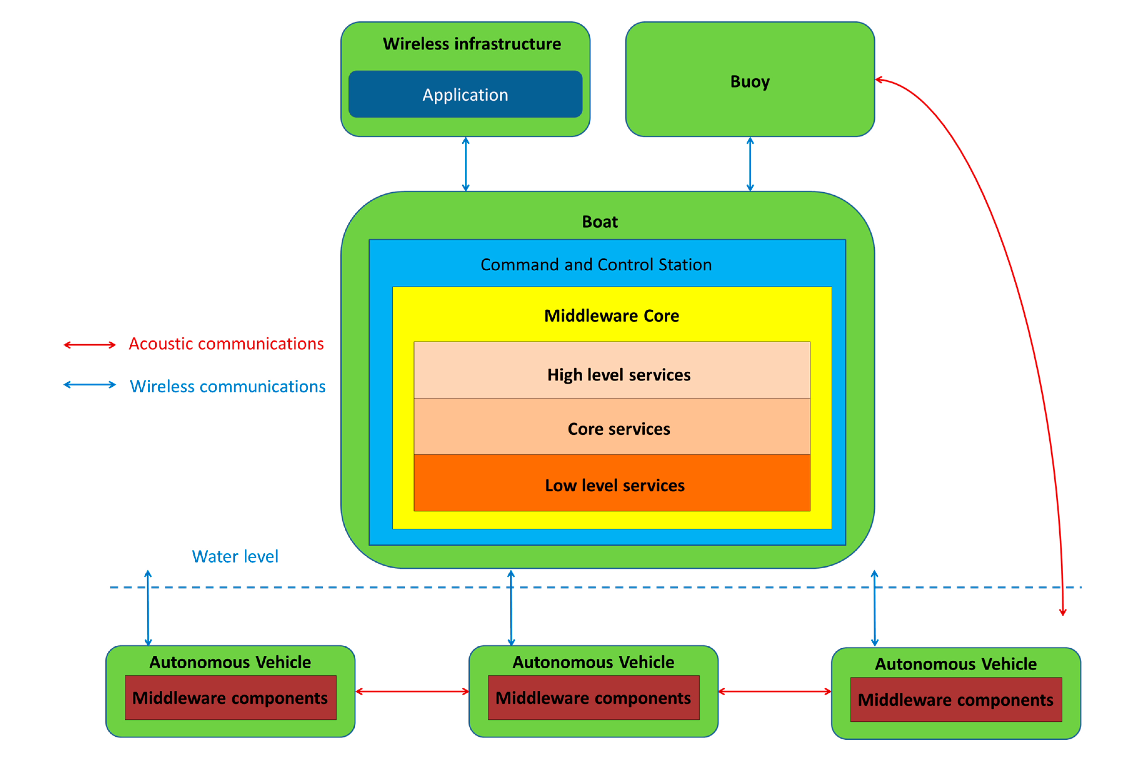
- Information of the entity that started the communication must be sent. The system running in the SWARMs project relies on the interchange of information at the data level among two different entities: the autonomous maritime vehicles and the equipment where all the other middleware elements have been included, which is referred to as the CCS. Depending on whether the vehicle or the middleware are publishing information or are subscribed to receive it, different PDUs must be used and different data will be included. Note that using protocols to measure flow information using TCP/IP layered architectures, such as IPFIX [41], would not be useful in this environment, due to the fact that a significant amount of communications will not rely on a regular IP infrastructure.
- Communication channel. The message can be transmitted either overwater or underwater, using an IP or an acoustic communication channel which highly influences the speed and amount of bytes that can be efficiently delivered from the sender to the receiver. The most evident consequence to deal with is that the PDUs that are more verbose will be sent via the IP network. Even though it cannot be cabled by any means, any network relying on already established standards for wireless communications will work in an easier way than at the acoustic level.
- Periodicity of the message. There will be messages that will be sent periodically as in any other distributed system or CPS. Commonly, these ones will be related to periodic heartbeats or keep alive notifications used to communicate both the autonomous maritime vehicles with each other, along with the CCS.
- Purpose of the message. Depending on the nature of the information contained in the message (data requests, GPS coordinates, etc.) the messages that are used will be interchanged depending on what has been requested and the availability of information.
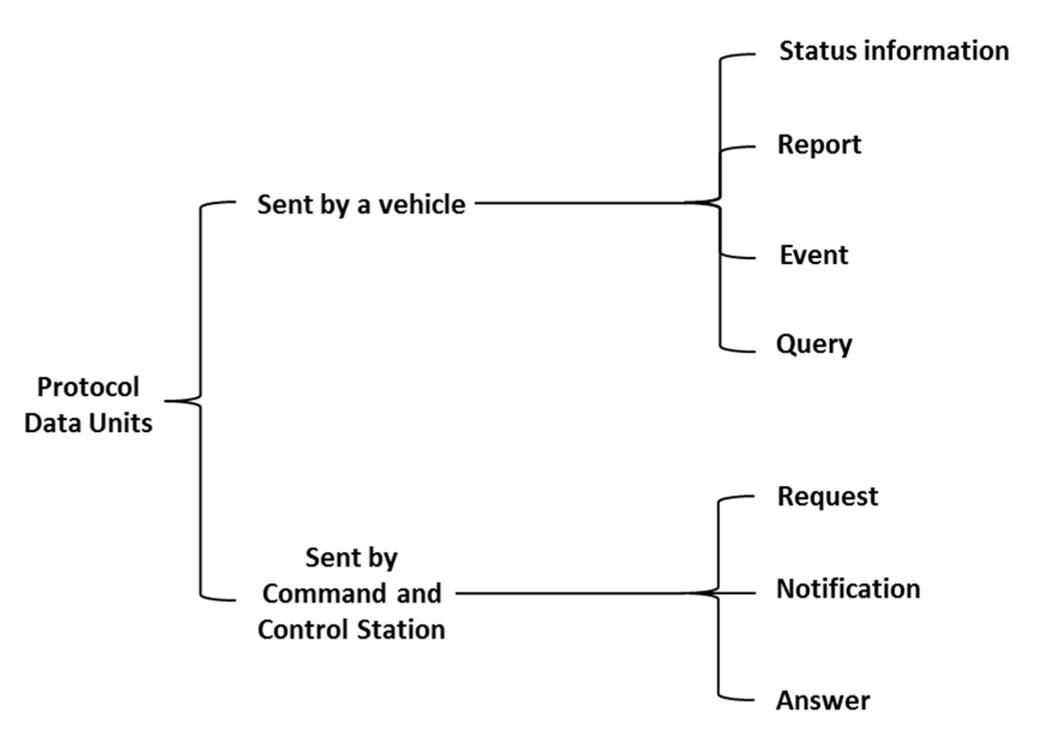
3.2. Taxonomy of Messages
- Status information is published periodically and usually corresponds to proprioceptive data, i.e., data about the vehicle itself, such as its estimated position or speed.
- A report is a collection of data about the vehicle or its environment (exteroceptive data) aggregated to answer to some request received by the vehicle. A report can be of several types depending of the incoming request. A report will always have a reference to the request message which triggered its processing.
- An event is a message sent by the vehicle to inform other entities involved in the mission that something relevant occurred which should be taken into consideration. Events can be either alarms or detections. Alarms result from detection by the Fault Management system of a failure or an anomaly in the behaviour of one or more components or subsystems of the vehicle, e.g., a loss of battery level, an increase of the internal temperature, the detection of a leak, etc. An alarm is therefore always related to proprioceptive onboard capabilities. On the other hand, a detection results from the observation of the environment of the vehicle either directly by a sensor (altimeter for instance) or through some processing.
- A query can be defined as a request sent by the vehicle to other entities participating in a data interchange during a maritime mission (such as the CCS or another autonomous maritime vehicle) in order to obtain certain information of interest (e.g., request for an update of the position of other vehicles involved in the mission) or asking for some processing which cannot be done onboard. A query will be processed through the middleware and will result (with a certain delay) in an answer message.
- A request is an inquiry message that once interpreted by the vehicle will result in a report. There are two types of inquiries depending on whether they are about the mission or about status data. A mission request results in the assignment to the vehicle of a goal, a high level task or a plan to be executed. Attribution of goals or high level tasks require that the vehicle has onboard planning capabilities. A status request usually asks about an update on some kind of proprioceptive data such as remaining autonomy or estimated position.
- A notification is a message to inform the vehicle that some new relevant information is available. Notifications may or may not require an action by the vehicle. Therefore, they do not imply an answer and could be even ignored by the vehicle. In order to receive a notification, it is mandatory that the vehicle previously subscribes to this kind of information as the middleware that is being used follows a publish/subscription paradigm. Once a notification is received, the vehicle may need to send and explicit query to retrieve associated content. For instance, if notified that there is an updated seabed map available, the vehicle would need to surface, send a query to receive it via radio frequency communications, analyze it and replan the mission if necessary.
- An answer is a message sent in response to a query emitted by a vehicle. Answers will always have a reference to the query message which triggered its processing.
3.3. Messages from the Maritime Data Transfer Protocol
- Environment data. These are the data that are related to the surroundings of the location where the autonomous maritime vehicles are deployed.
- Status: The pieces of information collected from here are about the vehicle that has been deployed. They complement the environment data because status data offer the information that was omitted by them.
- Situational information: The data deal with the location and movements of the autonomous maritime vehicle that is deployed, such as location, turning parameters or vehicle speed.
- Other information: These data contain all the information about other features of a deployment, like the algorithm that has been used for positioning.
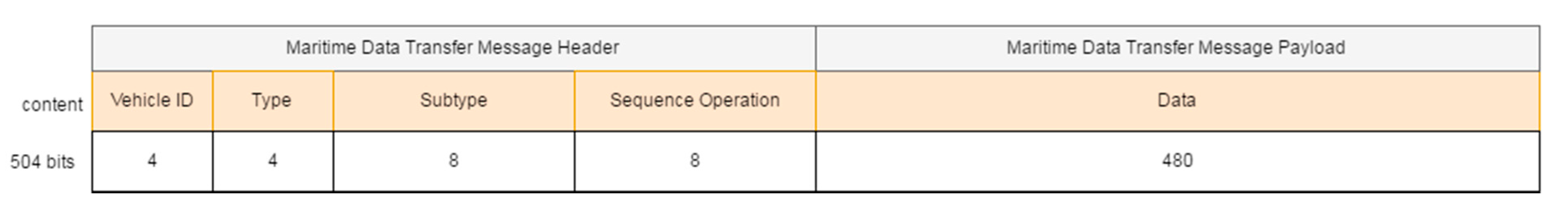
- Type (4 bits): PDU type. We consider 7 different kinds of PDUs according to the taxonomy of messages defined. Three of them represent the different message types the middleware can send to a vehicle: requests, notifications and answers. The other four represent the message types that vehicles can send to the middleware: periodic status information, reports, events and queries.
- Subtype (8 bits): PDU subtype. These bits are used to further define the kind of PDU that is sent within the 7 PDU types that have been defined previously.
- Sequence Operation (8 bits): randomly generated number used to relate petitions and responses.
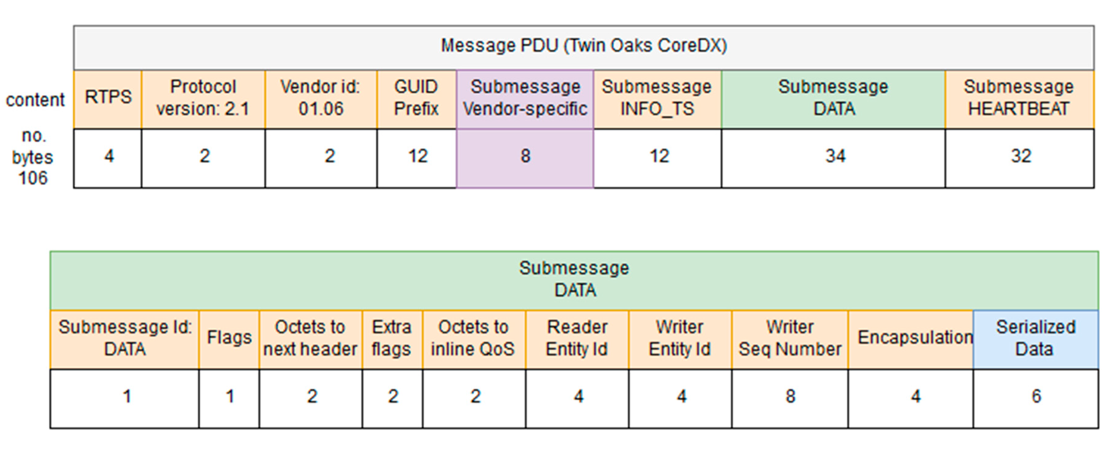
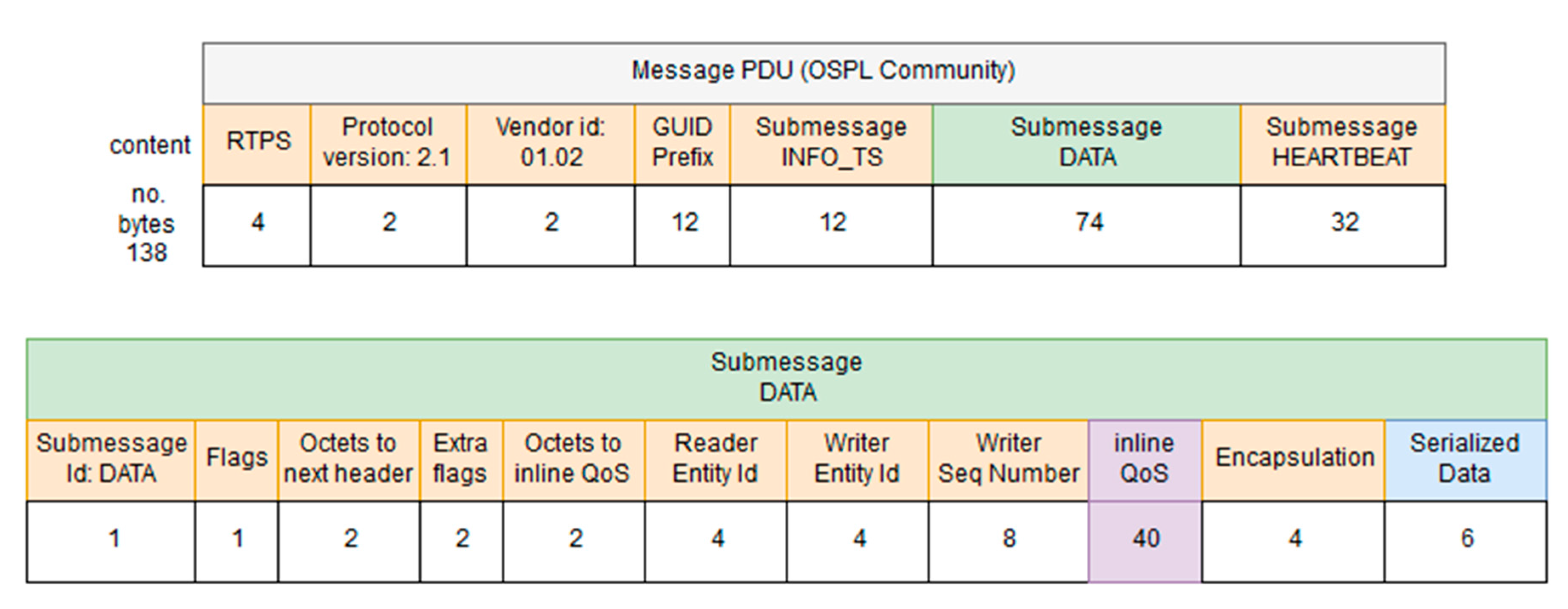
- Data (480 bits): 60 bytes available to transfer data. Depending on the message type and subtype, some of these data bytes may be empty. The timestamp associated to this data will be provided by the INFO_TS submessage of the DDS message.
- RTPS: this field is used to include the RTPS version that is used by the PDUs included in a DDS iteration.
- Protocol version: used to include the protocol version used in this iteration.
- Vendor ID: an identifier of the vendor that has developed the DDS iteration.
- GUID prefix: it is the Globally Unique Identifier used to characterize the message that is sent via DDS.
- Submessage INFO_TS: contains information about the timestamp of the message that was sent.
- Submessage data: contains the information transferred.
- Submessage heartbeat: used to control the periodicity of the information.
3.4. Serialized Data
- Overwater communications (IP channel). As there will not be any bandwidth limitation in this case, the middleware will take advantage of this situation to exchange data with vehicles whose size is expected to be large, like mission plans, that after being defined by the operators of the missions will be transmitted from the middleware to the AUVs before launching them to sea (e.g., if they are on a ship). Table 4 has been used to include all the pieces of information mentioned. In addition to that, the PDUs that are involved in the communications have also been included. They follow the structure that was described, which consists of a vehicle identifier (VID), the type of PDU that is used, its subtype (it is required because there are several different kinds of requests, reports or events that can be triggered in a mission), its sequence operation (included as SeqOp) and the data used to make the task possible.
- Underwater communications (acoustic channel). Will make use of PDUs with smaller amounts of data. As it was done in Table 4, the PDUs involved in the communications have also been included. The main reason for MDTP to have been designed is this kind of communication; if only Over-the-air data transmissions existed, it is likely that a different solution would have been studied. However, as described in the open issues, none of the existing options seemed to completely satisfy the required capabilities for data transmissions.
4. Implementation and Testing Activities on MDTP
4.1. Implementation Works
- A Java component that represents the publish-subscription manager of the middleware, in charge of the DDS communication with the AUVs. The DDS functionalities of this component are implemented by means of CoreDX DDS, a proprietary DDS solution offered by Twin Oaks [43].
- A C++ component that represents the DDS proxy of the AUV. This component is composed by two different layers: a communication layer in charge of DDS communication with the middleware, and a translation layer in charge of formatting the information to/from the language or commands supported by the AUV (e.g., ROS). This manuscript focuses on the communication layer, as the purpose of the authors is to validate the PDUs defined under MDTP. The DDS functionalities of the DDS proxy are implemented by means of Vortex OpenSplice DDS Community Edition which is an open-source DDS solution offered by PrismTech [44].
module swarmsIDL
{
struct SWARMsmsg
{
  octet vid_type;      //8 bits (VID bits 7..4, Type bits 3..0)
  octet _subtype;      //8 bits
  octet seqoperation;   //Sequence nr of the operation (8 bits)
  unsigned long dataInt[15];  //15 x 32 bits

};

};
The first byte represents the Vehicle ID (4 bits) and the Type (4 bits) of MDTP, while the second and the third byte represent the SubType and the Sequence Operation (all of them described in Section 3.3). Finally, 60 bytes have been reserved to transfer data, although the authors of the proposal are aware that not all transmissions will need such an amount of data, so in some cases part of these data bytes may be empty.4.2. Specific PDU Tests
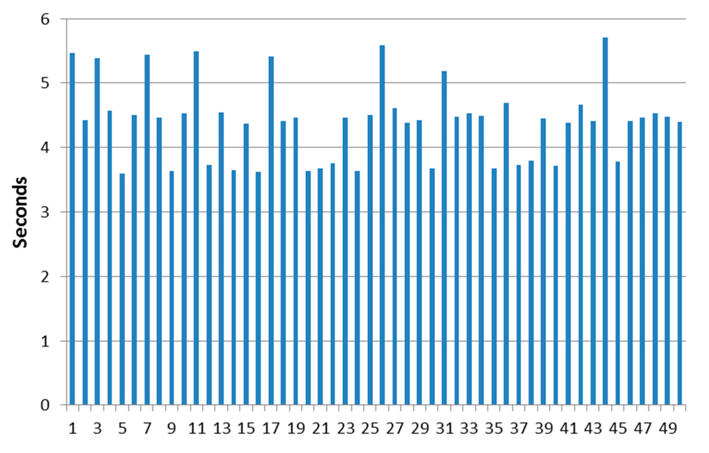
4.2.1. Test Case 1: Subscription to Periodic Environmental Data
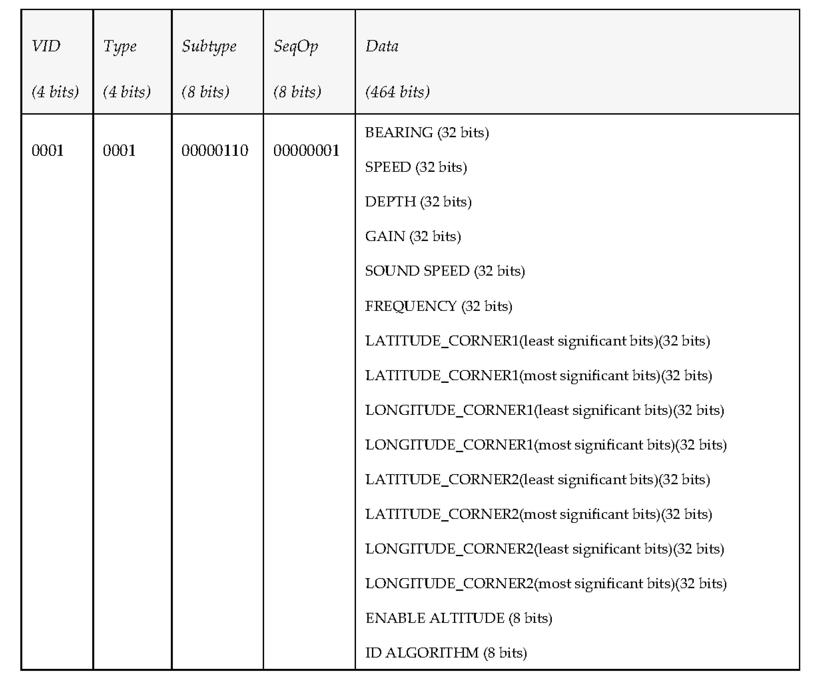
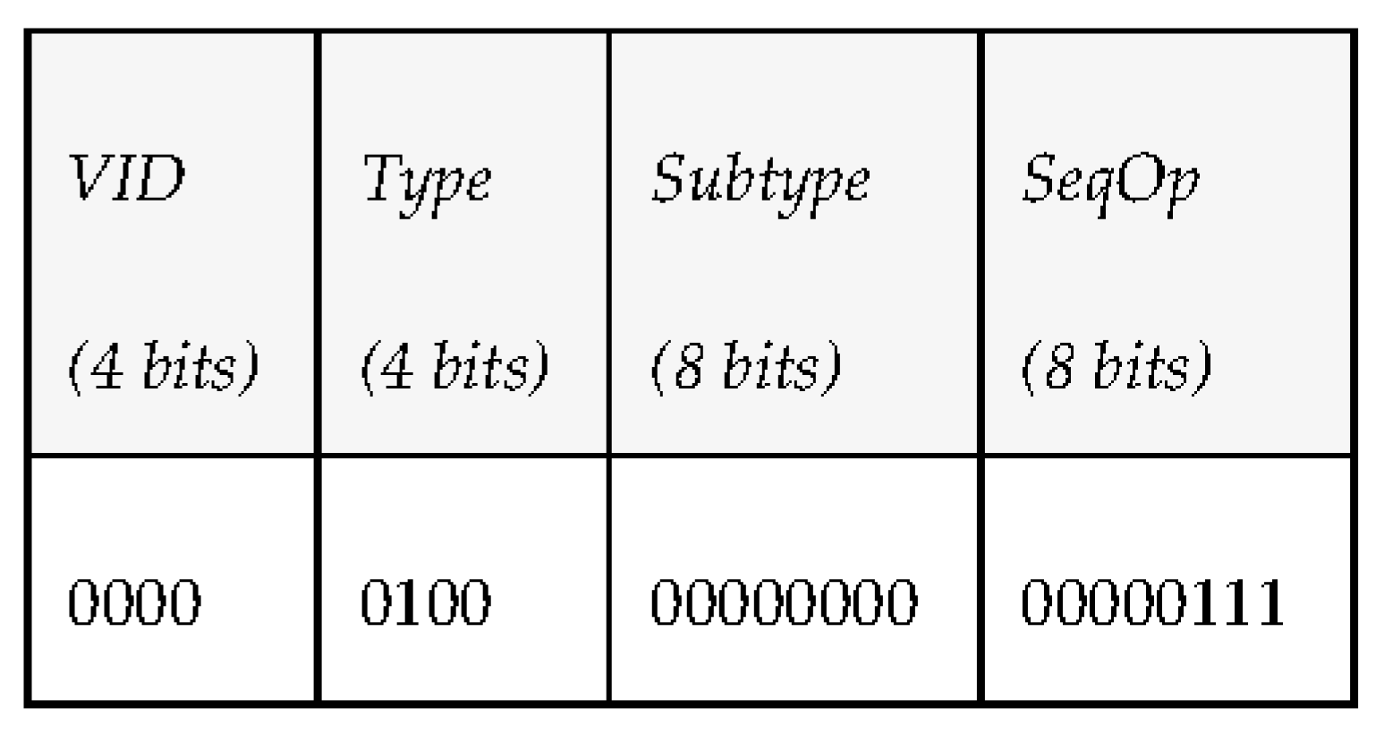
4.2.2. Testing Case 2: Task Execution Request
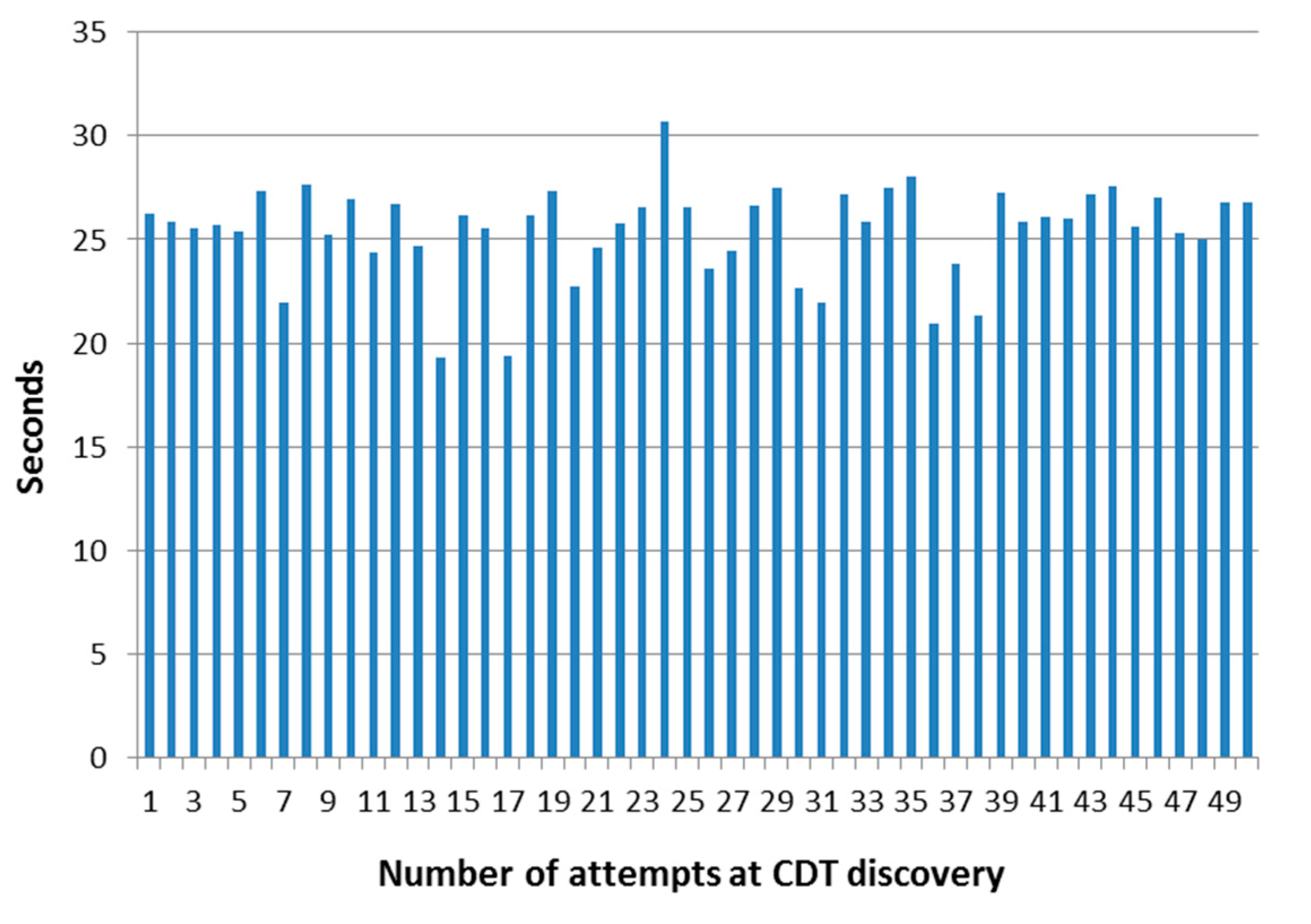
4.2.3. Testing Case 3: Discovery of Control Data Terminal Component
4.2.4. Other Testing Activities
4.3. Discussion of the Development Work
- A nominal bitrate of 1 kbps is quite common for underwater communications. While limitations on the bandwidth for underwater communications have been explained in this manuscript, it must be taken into account that 1 kbit per second data transmission are the usual ones present in acoustic communications. It is because of this reason that PDUs cannot be larger than a certain limit of bytes, or otherwise data will be lost. At the same time, trying to send information in single PDUs that do not relay on other ones to provide all the information requested is also something to consider, as such a procedure will maximize the chances of having all the data correctly delivered to the destination.
- The simulator that has been used to mimic the behaviour of underwater communications in the open sea is based on what is used in the SWARMs project, that is to say, the model S2C18/34 manufactured by Evologics (Berlin, Germany), which matches the required performance for transmission of data over relatively large distances (up to 3.5 km) with data rate up to 13.8 kbps (nominally). Although this bitrate will usually fall well below this figure when communications take place in shallow waters (due to reflections in the acoustic waves), it will still be usable to transmit information.
- If one acoustic modem is responsible to transmit the periodic data sent by several AUVs, the period for the transmission of periodic data will be no lower than 10 or 15 s in order to have the acoustic modem working correctly. This is due to the fact that, due to the characteristics of the environment where data transmissions take place, it is not advisable to establish periodic data transfers at a rate of milliseconds, especially if there are several vehicles transmitting information at the same time, because they might overall the modem, regardless of the strategy used to send that information (for example, if too many PDUs gather at a point, the modem will give priority to the first data received, in a First-In-First-Out fashion).
5. Conclusions and Future Works
Acknowledgments
Author Contributions
Conflicts of Interest
References
- Rajkumar, R.; Lee, I.; Sha, L.; Stankovic, J. Cyber-physical systems: The next computing revolution. In Proceedings of the 47th ACM/IEEE Design Automation Conference, Anaheim, CA, USA, 13–18 June 2010. [Google Scholar]
- Bradley, J.; Atkins, E. Optimization and Control of Cyber-Physical Vehicle Systems. Sensors 2015, 15, 23020–23049. [Google Scholar] [CrossRef] [PubMed]
- Hernández, J.D.; Istenič, K.; Gracias, N.; Palomeras, N.; Campos, R.; Vidal, E.; García, R.; Carreras, M. Autonomous Underwater Navigation and Optical Mapping in Unknown Natural Environments. Sensors 2016, 16, 1174. [Google Scholar] [CrossRef] [PubMed]
- Mei, J.H.; Arshad, M.R. COLREGs based navigation of riverine Autonomous Surface Vehicle. In Proceedings of the 2016 IEEE International Conference on Underwater System Technology: Theory and Applications (USYS), Penang, Malaysia, 13–14 December 2016. [Google Scholar]
- Koo, J.; Jung, S.; Myung, H. A jellyfish distribution management system using an unmanned aerial vehicle and unmanned surface vehicles. In Proceedings of the 2017 IEEE Underwater Technology (UT), Busan, Korea, 21–24 February 2017. [Google Scholar]
- Caraivan, M.; Dache, V.; Sgârciu, V. Simulation Scenarios for Deploying Underwater Safe-Net Sensor Networks Using Remote Operated Vehicles: Offshore Exploration Constructions Models and Sensor Deployment Methods. In Proceedings of the 2013 19th International Conference on Control Systems and Computer Science, Bucharest, Romania, 29–31 May 2013. [Google Scholar]
- Li, N.; Martínez, J.-F.; Rodríguez-Molina, J.; Meneses Chaus, J.M.; Eckert, M. A Survey on Underwater Acoustic Sensor Network Routing Protocols. Sensors 2016, 16, 414. [Google Scholar] [CrossRef] [PubMed]
- Martins, R. Disruption/delay tolerant networking with low-bandwidth underwater acoustic modems. In Proceedings of the 2010 IEEE/OES Autonomous Underwater Vehicles, Monterey, CA, USA, 1–3 September 2010. [Google Scholar]
- Chitre, M.; Shahabudeen, S.; Stojanovic, M. Underwater Acoustic Communication: Its Challenges and Research Opportunities. Mar. Technol. Soc. J. 2008, 42, 14. [Google Scholar] [CrossRef]
- Lloret, J.; Sendra, S.; Ardid, M.; Rodrigues, J.J.P.C. Underwater Wireless Sensor Communications in the 2.4 GHz ISM Frequency Band. Sensors 2012, 12, 4237–4264. [Google Scholar] [PubMed]
- Qureshi, U.M.; Shaikh, F.K.; Aziz, Z.; Shah, S.M.; Sheikh, A.A.; Felemban, E.; Qaisar, S.B. RF Path and Absorption Loss Estimation for Underwater Wireless Sensor Networks in Different Water Environments. Sensors 2016, 16, 890. [Google Scholar] [CrossRef] [PubMed]
- Lyalinov, M.A. Scattering of acoustic waves by a sector. Wave Motion 2013, 50, 739–762. [Google Scholar] [CrossRef]
- Stojanovic, M. Underwater Acoustic Communications. 2003. Available online: http://millitsa.coe.neu.edu/sites/millitsa.coe.neu.edu./files/ency3.pdf (accessed on 7 June 2017).
- Liu, L.; Zhou, S.; Cui, J.-H. Prospects and problems of wireless communication for underwater sensor networks. Wirel. Commun. Mob. Comput. 2008, 8, 977–994. [Google Scholar]
- SWARMs Consortium. SWARMs Early Trials. 2016. Available online: http://www.swarms.eu/PDFs/Newsl/SWARMs_Newsletter2_January2017.pdf (accessed on 17 April 2017).
- Beaujean, P.P.J.; Carlson, E.A.; Spruance, J.; Kriel, D. HERMES—A high-speed acoustic modem for real-time transmission of uncompressed image and status transmission in port environment and very shallow water. In Proceedings of the OCEANS 2008, Quebec City, QC, Canada, 15–18 September 2008. [Google Scholar]
- Naiad Team. Naiad for a Better Future. 2017. Available online: http://naiad.se/ (accessed on 17 April 2017).
- Hydroid Inc. New Generation REMUS 100. 2017. Available online: https://www.hydroid.com/NewGenREMUS (accessed on 17 April 2017).
- ECA Group. ECA A9-M. 2017. Available online: http://eca-media.ecagroup.com/player/pdf?key=c618ddf7338ea3f9c7c392bc127ebcb5 (accesssed on 17 April 2017).
- SWARMs Consortium. SWARMs: Smart and Networking UnderWAter Robots in Cooperation Meshes. 2015. Available online: http://www.swarms.eu/ (accessed on 2 June 2017).
- Tian, G.; Camtepe, S.; Tian, Y.C. A Deadline-Constrained 802.11 MAC Protocol With QoS Differentiation for Soft Real-Time Control. IEEE Transac. Ind. Inf. 2016, 12, 544–554. [Google Scholar]
- Internet Engineering Task Force (IETF). Request For Comments 7252—The Constrained Application Protocol RFC 7252(CoAP); Internet Engineering Task Force (IETF): Bremen, Germany, 2014. [Google Scholar]
- Fielding, R.T. Architectural Styles and the Design of Network-Based Software Architectures. 2000. Available online: http://www.ics.uci.edu/~fielding/pubs/dissertation/fielding_dissertation.pdf (accessed on 8 December 2016).
- AMQP Consortium. AMQP 1.0 Becomes OASIS Standard. 2012. Available online: http://www.amqp.org/node/102 (accessed on 2 June 2017).
- Apache Software Foundation. Apache Qpid. 2017. Available online: https://qpid.apache.org/index.html (accessed on 2 June 2017).
- Pivotal Software Inc. RabbitMQ. 2017. Available online: https://www.rabbitmq.com/ (accessed on 20 April 2017).
- Qian, L.; Zhang, S.; Liu, M.; Zhang, Q. A MACA-based power control MAC protocol for Underwater Wireless Sensor Networks. In Proceedings of the 2016 IEEE/OES China Ocean Acoustics (COA), Harbin, China, 9–11 January 2016. [Google Scholar]
- Chenn-Jung, H.; Yu-Wu, W.; Hsiu-Hui, L.; Chin-Fa, L.; Kai-Wen, H.; Tun-Yu, C. A power-efficient routing protocol for underwater wireless sensor networks. Appl. Soft Comput. 2011, 11, 2348–2355. [Google Scholar]
- MQTT Consortium. MQTT Version 3.1.1. 2014. Available online: http://docs.oasis-open.org/mqtt/mqtt/v3.1.1/os/mqtt-v3.1.1-os.pdf (accessed on 8 December 2016).
- Locke, D. MQ Telemetry Transport (MQTT) V3.1 Protocol Specification; IBM DeveloperWorks Technical Library: Armonk, NY, USA, 2010. [Google Scholar]
- Thangavel, D.; Ma, X.; Valera, A.; Tan, H.-X.; Tan, C.K.-Y. Performance evaluation of MQTT and CoAP via a common middleware. In Proceedings of the IEEE Ninth International Conference on Intelligent Sensors, Sensor Networks and Information Processing (ISSNIP), Singapore, 21–24 April 2014; p. 6. [Google Scholar]
- Karagiannis, V.; Chatzimisios, P.; Vazquez-Gallego, F.; Alonso-Zarate, J. A survey on application layer protocols for the Internet of Things. Trans. IoT Cloud Comput. 2015, 3, 11–17. [Google Scholar]
- Andy Stanford-Clark, H.L.T. MQTT For Sensor Networks (MQTT-SN) Protocol Specification; IBM: Armonk, NY, USA, 2013. [Google Scholar]
- Tolle, G. Internet Engineering Task Force (IETF). In Embedded Binary HTTP (EBHTTP); 2013; Available online: https://tools.ietf.org/html/draft-tolle-core-ebhttp-00 (accessed on 2 June 2017).
- Saint-Andre, P. Extensible Messaging and Presence Protocol (XMPP): Instant Messaging and Presence; 2014; Available online: https://xmpp.org/rfcs/rfc3921.html (accessed on 2 June 2017).
- Attarwala, A.; Jagdish, D.; Fischer, U. Real Time Collaborative Video Annotation Using Google App Engine and XMPP Protocol. In Proceedings of the 2011 IEEE 4th International Conference on Cloud Computing, Washington, DC, USA, 4–9 July 2011. [Google Scholar]
- Bendel, S.; Springer, T.; Schuster, D.; Schill, A.; Ackermann, R.; Ameling, M. A service infrastructure for the Internet of Things based on XMPP. In Proceedings of the 2013 IEEE International Conference on Pervasive Computing and Communications Workshops (PERCOM Workshops), San Diego, CA, USA, 18–22 March 2013. [Google Scholar]
- Tian, L.; OMA Device Management Working Group (OMA DM WG). Lightweight M2M (OMA LWM2M), 2012.
- Gholkar, V. An Introduction to IoT Protocols; O’Reilly: Portland, OR, USA, 2014. [Google Scholar]
- Díaz, V.H.; Martínez, J.F.; Cuerva, A.; Rodríguez-Molina, J.; Rubio, G.; Jara, A. Semantic as an Interoperability Enabler in Internet of Things. In Internet of Things: Converging Technologies for Smart Environments and Integrated Ecosystems; Vermesan, O., Friess, P., Eds.; River Publishers: Aalborg, Denmark, 2013. [Google Scholar]
- Internet Engineering Task Force RFC 7011. Specification of the IP Flow Information Export (IPFIX) Protocol for the Exchange of Flow Information. 2013. Available online: https://tools.ietf.org/html/rfc7011 (accessed on 2 June 2017).
- Object Management Group. Documents Associated with The Real-Time Publish-Subscribe Wire Protocol DDS Interoperability Wire Protocol Specification, V2.2. 2016. Available online: http://www.omg.org/spec/DDSI-RTPS/2.2/ (accessed on 25 February 2017).
- Twin Oaks Computing Inc. CoreDX DDS Developer Documentation. Java Programmer's Guide; Twin Oaks Computing Inc.: Castle Rock, CO, USA, 2016. [Google Scholar]
- Prismtech Inc. Vortex OpenSplice Deployment Guide; Prismtech Inc.: Stirling, UK, 2016. [Google Scholar]
- Real-Time Innovations. RTI Connext DDS. 2017. Available online: https://www.rti.com/products (accessed on 25 February 2017).
- Kebkal, O.G.; Kebkal, K.G.; Komar, M. Development of upper-layer protocols with S2CR acoustic modems emulator. In Proceedings of the Conference on Underwater Communications: Channel Modelling and Validation, UCOMMS, Sestri Levante, Italy, September 2012. [Google Scholar]
- Oracle, Inc. Oracle® Fusion Middleware. Performance and Tuning Guide; 11g Release 1 (11.1.1); Oracle, Inc.: Redwood Shores, CA, USA, 2012. [Google Scholar]
- Red Hat, Inc. Nest Practices for Performance Tuning. JBoss Enterprise Application Platform 5. 2010. Available online: https://www.redhat.com/f/pdf/JB_JEAP5_PerformanceTuning_wp_web.pdf (accessed on 2 June 2017).
- Korhonen, M. Message Oriented Middleware (MOM); Internetworking Seminar; Department of Computer Science, Helsinki University of Technology: Espoo, Finland, 2015. [Google Scholar]


| Name of the Proposal | Advantages | Disadvantages | References |
|---|---|---|---|
| Deadline-Constrained 802.11 MAC | Accurate definition of information transfers in the transmission medium. | Works at a lower level (physical and network access layers rather than middleware or data-based ones). | Tian, G., S. Camtepe, and Y.C. Tian, A Deadline-Constrained 802.11 MAC Protocol With QoS Differentiation for Soft Real-Time Control [21]. |
| Constrained Application Protocol | PDU definition and interchange are thoroughly described. It has been designed for constrained environments. | Conceived for the application layer rather than a level below. | Internet Engineering Task Force (IETF), The Constrained Application Protocol, RFC 7252 (CoAP) [22]. |
| Advanced Message Queuing Protocol | Set of PDUs for information transmission at the data level. It has a broker for Publish/Subscribe communications. | Conceived for reliable transmission mediums rather than an underwater channel. Adding security can be challenging. | AMQP consortium. AMQP 1.0 Becomes OASIS Standard [24]. |
| MACA-based power control | Reliable performance in underwater environments where bits are transmitted. | Focused on bit transmission, rather than data level with higher level information. | L. Qian, S. Zhang, M. Liu and Q. Zhang. A MACA-based power control MAC protocol for Underwater Wireless Sensor Networks [27]. |
| Power-efficient routing protocol | Optimized scheme for bit transmission. | It is not a suitable solution for transmissions at the data level. | Chenn-Jung Huang, Yu-Wu Wang, Hsiu-Hui Liao, Chin-Fa Lin, Kai-Wen Hu, Tun-Yu Chang. A power-efficient routing protocol for underwater wireless sensor networks [28]. |
| Message Queue Telemetry Transport | Solution suitable for distributed systems. | This proposal has not been conceived for underwater environments. | MQTT consortium. MQTT Version 3.1.1 [29]. Locke, D., Mq telemetry transport (mqtt) v3.1 protocol specification [30]. |
| MQTT-SN | Includes Publish/Subscribe communications. | It has been developed for sensor networks instead of underwater environments. | Andy Stanford-Clark, H.L.T., MQTT For Sensor Networks (MQTT-SN) Protocol Specification [33]. |
| Embedded binary HTTP | Small-sized transmissions with a similar approach to CoAP. | Solution conceived for the application layer rather than lower ones. Power demanded may be too much for constrained devices. | Tolle, G., Embedded Binary HTTP (EBHTTP) [34]. |
| Extensible Messaging and Presence Protocol | Enables security. Follows a CoAP approach. | Lack of Quality of Service capabilities. XML might be troublesome for underwater data transmissions. | Saint-Andre P (technical representative of the Internet Engineering Task Force, Extensible messaging and presence protocol (xmpp) [35]. |
| Lightweight M2M | Management of a wide range of embedded systems. | It is built on top of CoAP, so it is unsuitable for underwater data transmissions. | Tian L. OMA device management working group (OMA DM WG), Lightweight m2m (oma lwm2m) [38]. |
| Name of the Proposal | Disadvantages | Action Taken in MDTP to Deal with the Disadvantage |
|---|---|---|
| Deadline-Constrained 802.11 MAC | Works at a lower level (physical and network access layers rather than middleware or data-based ones). | MDTP is used at the data level for data-based information transfers. |
| Constrained Application Protocol | Conceived for the application layer rather than a level below. | Used at the data level (as PDUs used by a middleware solution) rather than one level above (application) or levels below (transport, network). |
| Advanced Message Queuing Protocol | Conceived for reliable transmission mediums rather than an underwater channel. Adding security can be challenging. | Designed for underwater transmissions (the ones deemed as more difficult) from scratch. Security is also offered as an option. |
| MACA-based power control | Focused on bit transmission, rather than data level with higher level information. | Used at the data level (as PDUs used by a middleware solution) rather than one level above (application) or levels below (transport, network). |
| Power-efficient routing protocol | It is not a suitable solution for transmissions at the data level. | Used at the data level (as PDUs used by a middleware solution) rather than one level above (application) or levels below (transport, network). |
| Message Queue Telemetry Transport | This proposal has not been conceived for underwater environments. | Designed for underwater transmissions (constrains and unreliability of the transmission medium are taken into account). |
| MQTT-SN | It has been developed for sensor networks instead of underwater environments. | Designed for underwater transmissions (constrains and unreliability of the transmission medium are taken into account). |
| Embedded binary HTTP | Solution conceived for the application layer rather than lower ones. Power demanded may be too much for constrained devices. It relies on a layered protocol architecture likely not to be present in an underwater environment. | MDPT can be used on top of regular IP networks or separately over underwater, acoustic-based deployments. |
| Extensible Messaging and Presence Protocol | Lack of Quality of Service capabilities. XML might be troublesome for underwater data transmissions. | Non-verbose format is used for data transmissions. QoS is guaranteed by its inclusion of MDTP in a DDS development. |
| Lightweight M2M | It is built on top of CoAP, so it is unsuitable for underwater data transmissions. | Designed for underwater transmissions (constrains and unreliability of the transmission medium are taken into account). |
| Data | Units | Size | Data Type | Range of Values |
|---|---|---|---|---|
| Environment data | ||||
| Water temperature | Celsius | 8 bits | Byte | −3.75–60.5 °C |
| Water salinity | Parts per million | 16 bits | Unsigned short | 0–65534 ppm |
| Sound Velocity | m/s | 32 bits | Float | 0.0–9999.999 m/s |
| Turbidity | Parts per million | 16 bits | Unsigned short | 0–65534 ppm |
| Pollution (H2S) | Parts per million | 16 bits | Unsigned short | 0–65534 ppm |
| Currents | cm/s | 8 bits | Unsigned byte | 0–254 cm/s |
| Bathymetry–underwater maps (sonar) | m | 32 bits | Float | 0.0–9999.999 m |
| Status | ||||
| Vehicle battery | % | 8 bits | Unsigned byte | 0.0–100.0% |
| Temporal reference | s | 16 bits | Unsigned byte | 0–65534 s |
| Sensor status | Bit identifier + bit mode | 8 bits (5 bits + 3 bits) | Unsigned short | 0–31 sensors, 0–8 modes |
| Vehicle event/alarm | Event or alarm code | 4 bits | Byte | 0000–1110 (15 different events/alarms) |
| Situational information | ||||
| Latitude | Degrees | 64 bits | Float | −90–90 |
| Longitude | Degrees | 64 bits | Float | −180 to 180 |
| Coordinates (Inertial/USBL/DVL) | cm/s | 8 bits | Unsigned byte | 0–254 cm/s |
| Working depth | m | 32 bits | Float | 0–4095.875 m |
| Euler Angles (Pitch) | Degrees | 32 bits | Float | 0.000–360.000° |
| Euler Angles (Roll) | Degrees | 32 bits | Float | 0.000–360.000° |
| Euler Angles (Yaw) | Degrees | 32 bits | Float | 0.000–360.000° |
| Distance to seabed | m | 16 bits | Unsigned short | 0–4095.875 m |
| Azimuth | Degrees | 32 bits | Float | 0.000–360.000° |
| Vehicle speed | m/s | 32 bits | Float | 0.0–127.99609375 m/s |
| Bearing | Rad | 32 bits | Float | [−π, π] |
| Gain | 32 bits | Float | ||
| Altitude | m | 8 bits | Float | |
| GSM | m/s | 32 bits | Float | |
| X | m | 32 bits | Float | |
| Y | m | 32 bits | Float | |
| Target Yaw | Degrees | 32 bits | Float | 0.000–360.000° |
| Target depth | m | 16 bits | Unsigned short | 0–4095.875 m |
| Others | ||||
| Algorithm Identifier | 8 bits | Octet | ||
| Message Type | Actions Involved | PDUs Involved | ||||
|---|---|---|---|---|---|---|
| Middleware Requests | ||||||
| New Task of a Mission | The middleware sends a request message with a new TASK of a mission. Tasks are defined by the subtype that is included in them. To define the mission, the middleware will send several PDUs like this one to specify the different tasks to accomplish. For example, the task “Go to take picture” is defined by the subtype “00000100”, task “hover to take a picture” by the subtype “00000101”, “cover area” by “00000110”, etc. | VID (4 bits) | Type (4 bits) | Subtype (8 bits) | SeqOp (8 bits) | Data (60 bytes) |
| ID | 0001 | 00000100 | NUM | TASK | ||
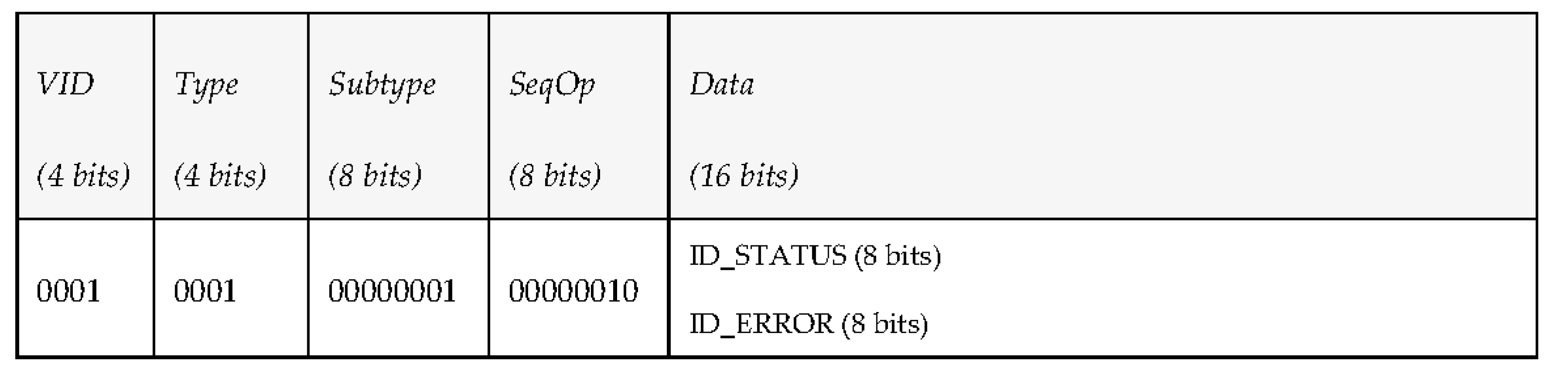
| The vehicle reports to the middleware whether the task was successfully registered (ACK = 00) or not (ERROR_ID). | VID (4 bits) | Type (4 bits | Subtype (8 bits) | SeqOp (8 bits) | Data (1 byte) | |
| ID | 0001 | 00000100 | NUM | ACK | ||
| Message Type | Actions Involved | PDUs Involved | ||||
|---|---|---|---|---|---|---|
| Vehicle Periodic Messages | ||||||
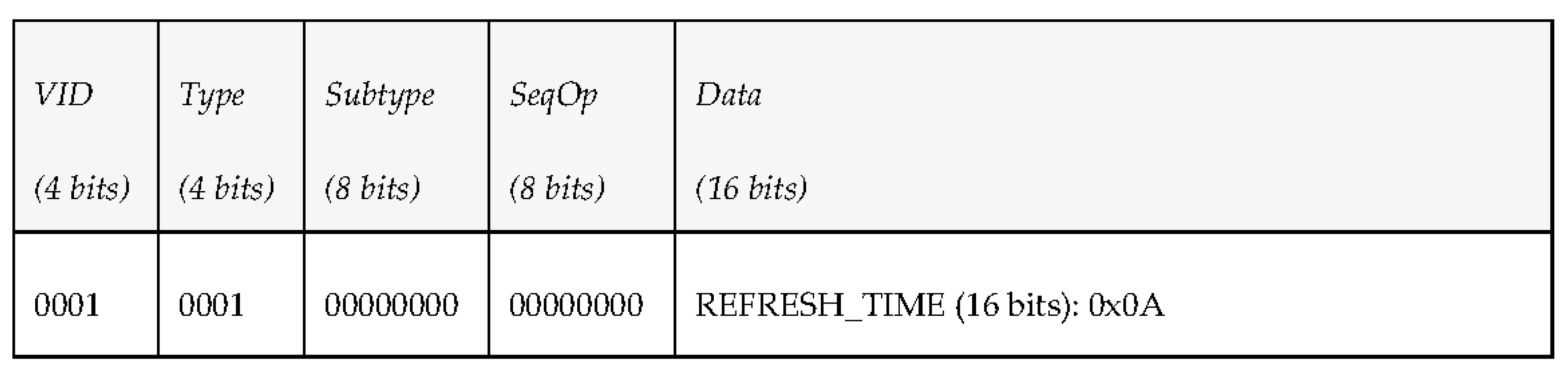
| Periodic Status Information | The middleware sends a request message to subscribe to periodic data of a vehicle, specifying the refresh time desired in seconds (REF_TIME). | VID (4 bits) | Type (4 bits) | Subtype (8 bits) | SeqOp (8 bits) | Data (2 bytes) |
| ID | 0001 | 00000000 | NUM | REF_TIME | ||
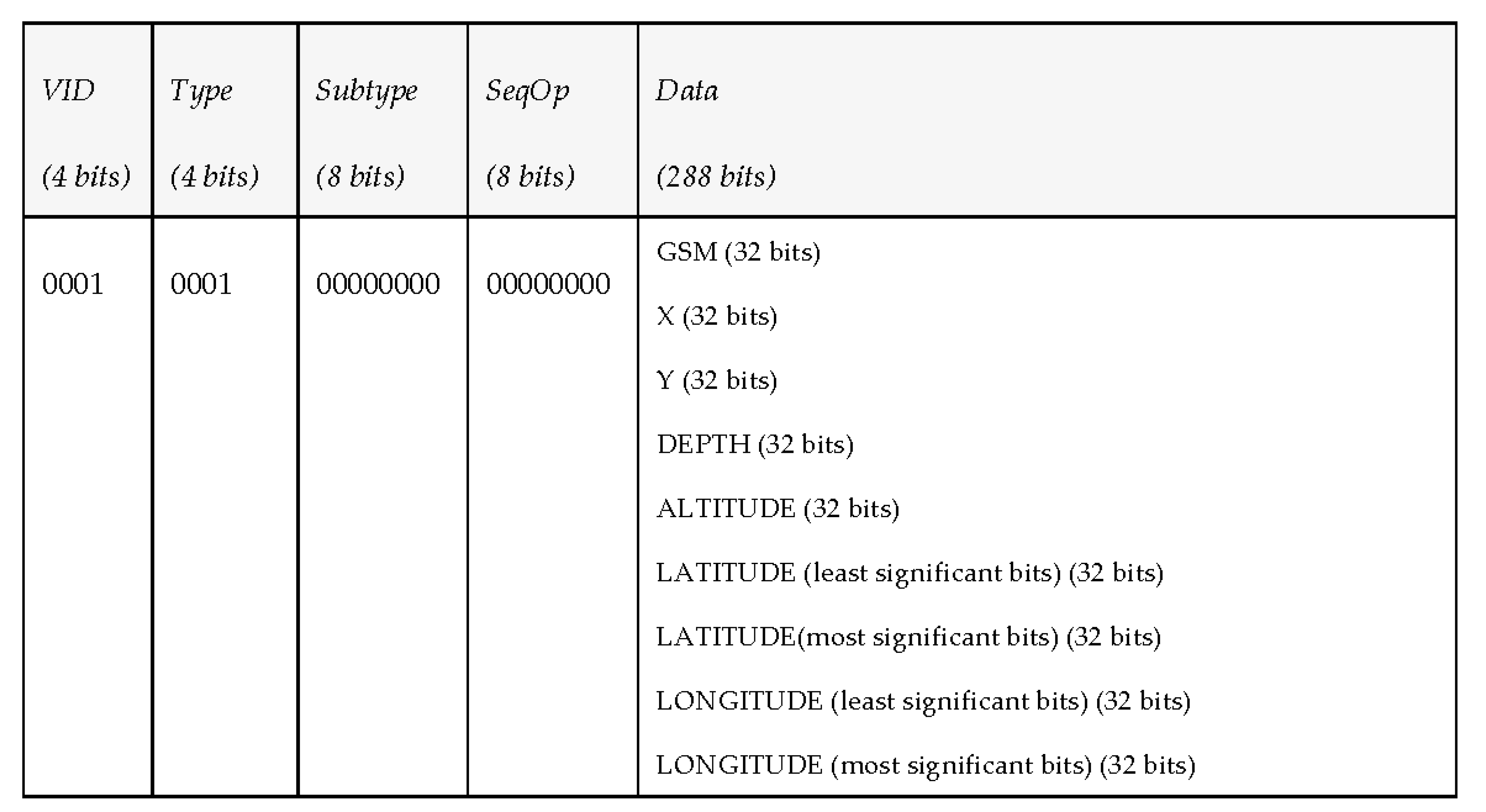
| The vehicle periodically reports about the kind of DATA that the middleware has subscribed to. | VID (4 bits) | Type (4 bits) | Subtype (8 bits) | SeqOp (8 bits) | Data (60 bytes) | |
| ID | 0001 | 00000000 | NUM | PDATA | ||
| Middleware Requests | ||||||
| Task Update | The middleware sends a request message with a new task (UTASK) of a mission. Tasks are as defined previously, and will be identified by the same kinds of subtypes. | VID (4 bits) | Type (4 bits) | Subtype (8 bits) | SeqOp (8 bits) | Data (60 bytes) |
| ID | 0001 | 10000010 | NUM | UTASK | ||
| The vehicle reports to the middleware whether the task was successfully registered (ACK = 00) or not (ERROR_ID). | VID (4 bits) | Type (4 bits) | Subtype (8 bits) | SeqOp (8 bits) | Data (1 byte) | |
| ID | 0001 | 10000010 | NUM | ACK | ||
| Configure Camera | The middleware request the vehicle to change the configuration of the camera. | VID (4 bits) | Type (4 bits) | Subtype (8 bits) | SeqOp (8 bits) | Data (60 bytes) |
| ID | 0001 | 10000001 | NUM | IMACON | ||
| The vehicle reports to the middleware whether the camera configuration was successfully done (ACK = 00) or not (ERROR_ID). | VID (4 bits) | Type (4 bits) | Subtype (8 bits) | SeqOp (8 bits) | Data (1 byte) | |
| ID | 0001 | 10000001 | NUM | ACK | ||
| Vehicle Events | ||||||
| Vehicle Alarms | The middleware subscribes to the alarms of the vehicle. | VID (4 bits) | Type (4 bits) | Subtype (8 bits) | SeqOp (8 bits) | Data (60 bytes) |
| ID | 0010 | 00000000 | NUM | SALARM | ||
| The vehicle sends information about the ALARMs the middleware is subscribed to. | VID (4 bits) | Type (4 bits) | Subtype (8 bits) | SeqOp (8 bits) | Data (60 bytes) | |
| ID | 0010 | 00000000 | NUM | ALARM | ||
| Vehicle Detections | The middleware subscribes to the detections of the vehicle. | VID (4 bits) | Type (4 bits) | Subtype (8 bits) | SeqOp (8 bits) | Data (60 bytes) |
| ID | 0010 | 00000001 | NUM | SDETEC | ||
| The vehicle sends the middleware information about some detection. | VID (4 bits) | Type (4 bits) | Subtype (8 bits) | SeqOp (8 bits) | Data (60 bytes) | |
| ID | 0010 | 00000001 | NUM | DETECT | ||
| Middleware Notifications | ||||||
| Middleware Notifications | The vehicle subscribes to notifications from the middleware. | VID (4 bits) | Type (4 bits) | Subtype (8 bits) | SeqOp (8 bits) | Data (60 bytes) |
| ID | 0010 | 00000010 | NUM | SNOTIFY | ||
| The middleware sends a notification. | VID (4 bits) | Type (4 bits) | Subtype (8 bits) | SeqOp (8 bits) | Data (60 bytes) | |
| ID | 0010 | 00000010 | NUM | NOTIFY | ||
| Vehicle Queries | ||||||
| Vehicle Queries | The vehicle queries the middleware. | VID (4 bits) | Type (4 bits) | Subtype (8 bits) | SeqOp (8 bits) | Data (60 bytes) |
| ID | 0011 | 00000000 | NUM | QUERY | ||
| The middleware answers the vehicle. | VID (4 bits) | Type (4 bits) | Subtype (8 bits) | SeqOp (8 bits) | Data (60 bytes) | |
| ID | 0011 | 00000000 | NUM | ANSWER | ||
| Request Attempt | Time (s) |
|---|---|
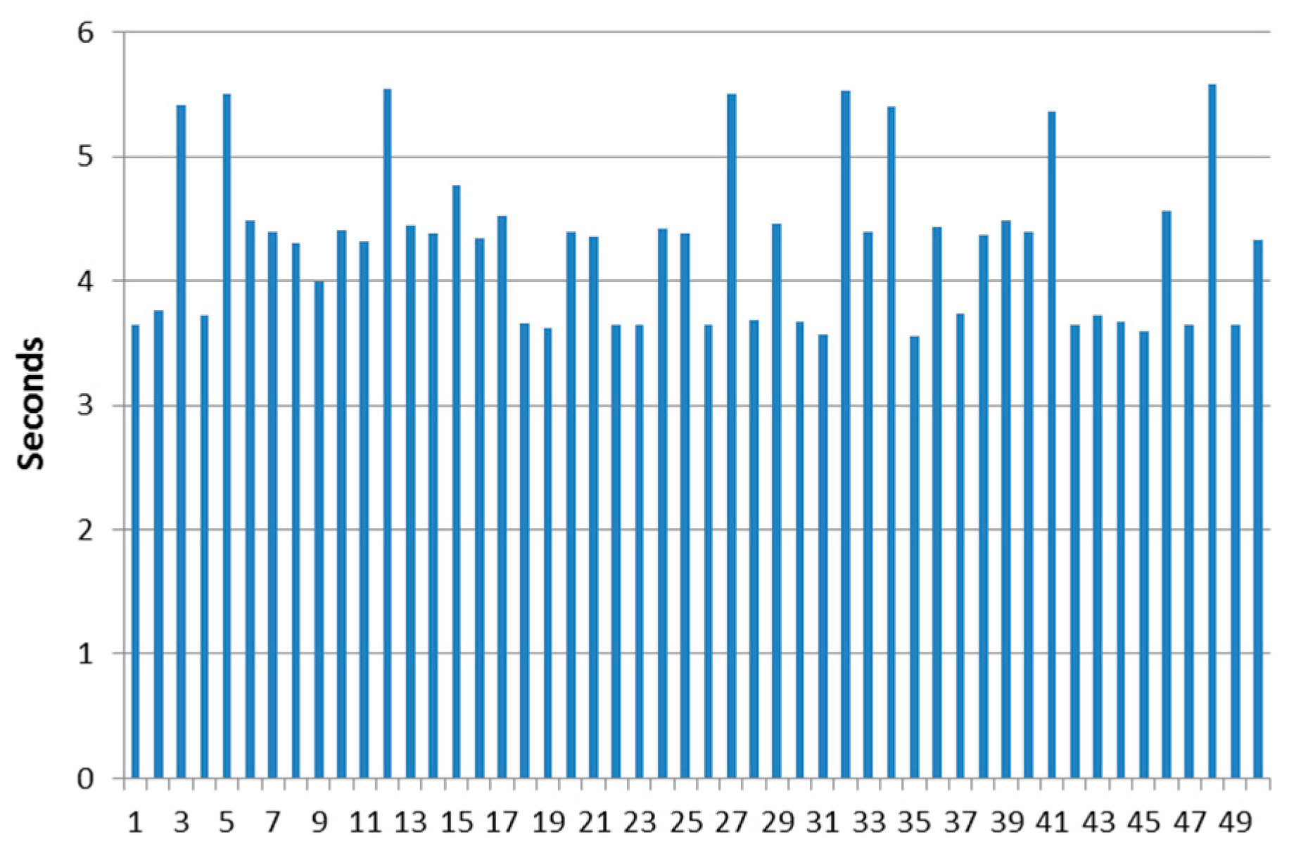
| Maximum | 5.58 |
| Minimum | 3.56 |
| Average | 4.2936 |
| Median | 4.365 |
| Standard deviation | 0.63554174 |
| Request Attempt | Time (s) |
|---|---|
| Maximum | 5.71 |
| Minimum | 3.6 |
| Average | 4.4002 |
| Median | 4.455 |
| Standard deviation | 0.59223027 |
| Request Attempt | Time (s) |
|---|---|
| Maximum | 30.67 |
| Minimum | 19.28 |
| Average | 25.4436 |
| Median | 25.855 |
| Standard deviation | 2.24441871 |
© 2017 by the authors. Licensee MDPI, Basel, Switzerland. This article is an open access article distributed under the terms and conditions of the Creative Commons Attribution (CC BY) license (http://creativecommons.org/licenses/by/4.0/).
Share and Cite
Rodríguez-Molina, J.; Martínez, B.; Bilbao, S.; Martín-Wanton, T. Maritime Data Transfer Protocol (MDTP): A Proposal for a Data Transmission Protocol in Resource-Constrained Underwater Environments Involving Cyber-Physical Systems. Sensors 2017, 17, 1330. https://doi.org/10.3390/s17061330
Rodríguez-Molina J, Martínez B, Bilbao S, Martín-Wanton T. Maritime Data Transfer Protocol (MDTP): A Proposal for a Data Transmission Protocol in Resource-Constrained Underwater Environments Involving Cyber-Physical Systems. Sensors. 2017; 17(6):1330. https://doi.org/10.3390/s17061330
Chicago/Turabian StyleRodríguez-Molina, Jesús, Belén Martínez, Sonia Bilbao, and Tamara Martín-Wanton. 2017. "Maritime Data Transfer Protocol (MDTP): A Proposal for a Data Transmission Protocol in Resource-Constrained Underwater Environments Involving Cyber-Physical Systems" Sensors 17, no. 6: 1330. https://doi.org/10.3390/s17061330
APA StyleRodríguez-Molina, J., Martínez, B., Bilbao, S., & Martín-Wanton, T. (2017). Maritime Data Transfer Protocol (MDTP): A Proposal for a Data Transmission Protocol in Resource-Constrained Underwater Environments Involving Cyber-Physical Systems. Sensors, 17(6), 1330. https://doi.org/10.3390/s17061330