
Amorphous SiC/c-ZnO-Based Quasi-Lamb Mode Sensor for Liquid Environments


Abstract
:1. Introduction
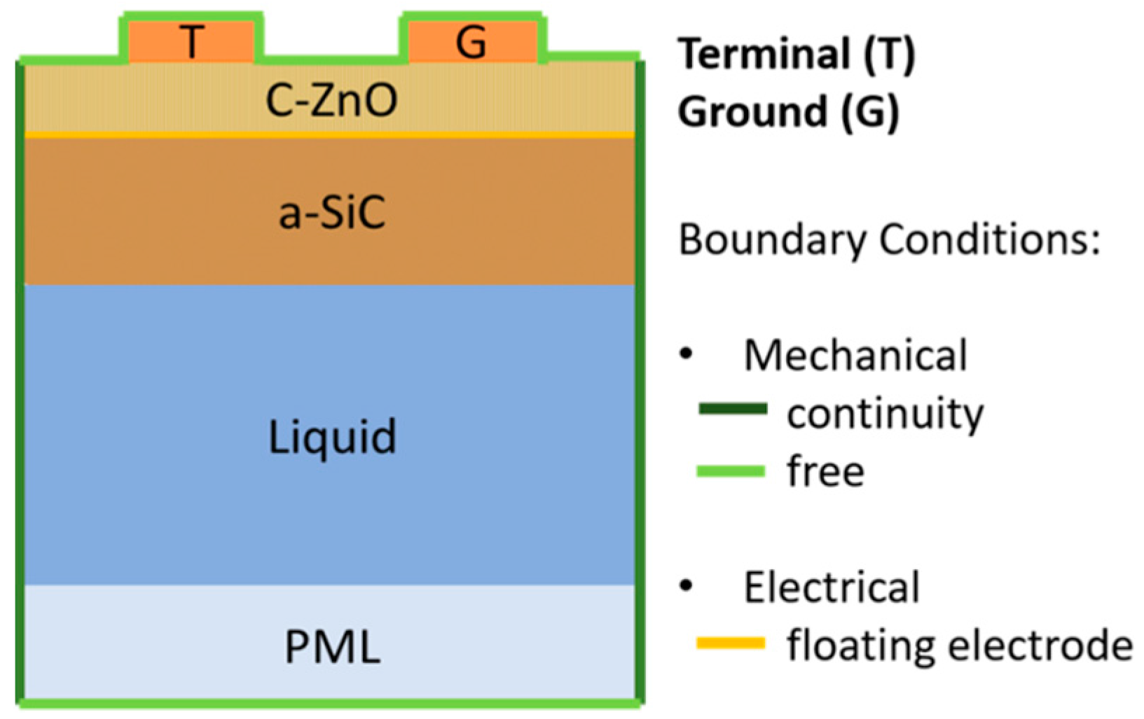
2. ZnO/a-SiC Plates
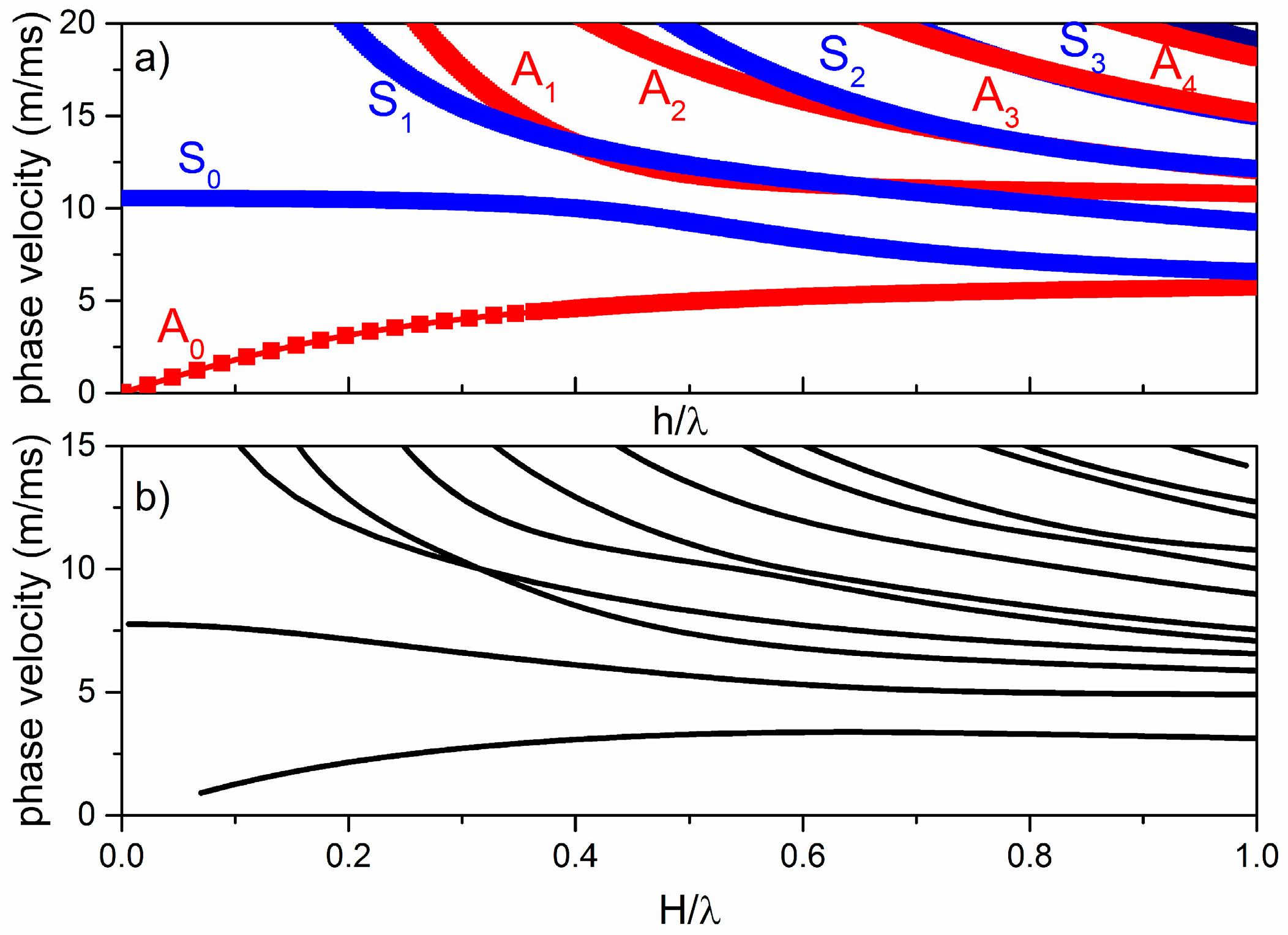
2.1. Phase Velocity Dispersion Curves
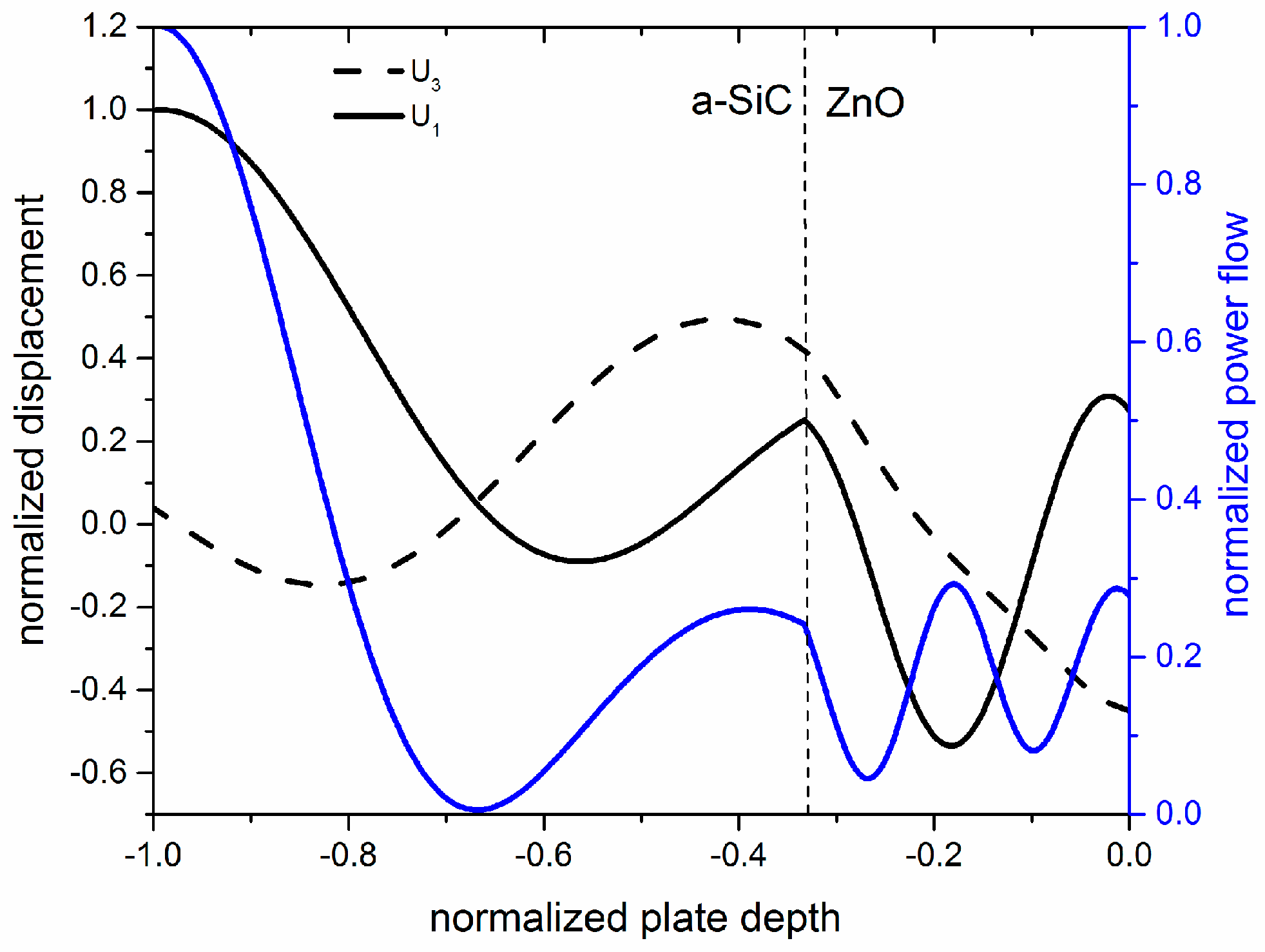
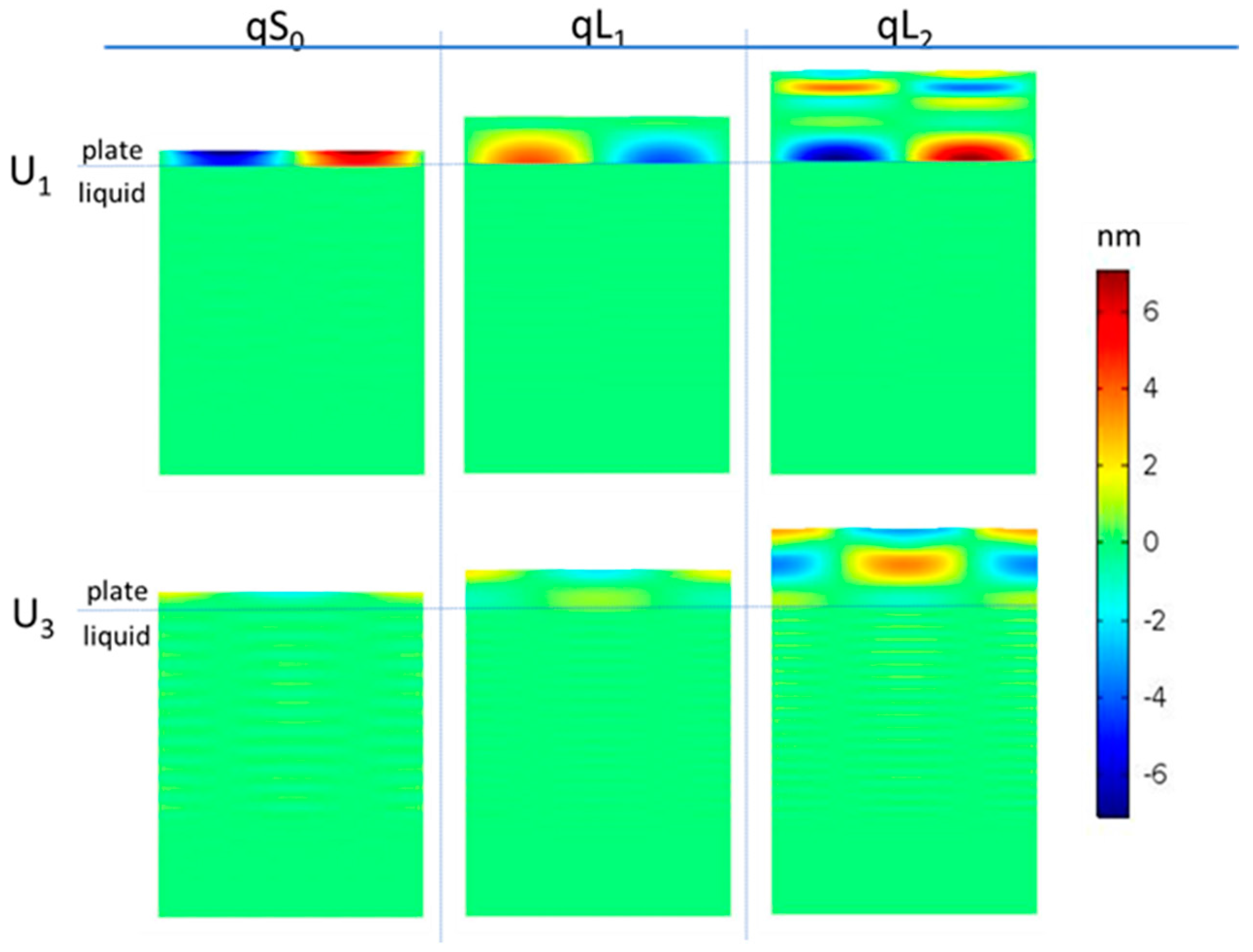
2.2. Displacement Profile
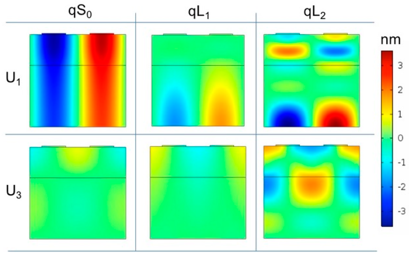
2.2.1. The qS0 Mode
2.2.2. The qL1 and qL2 Modes
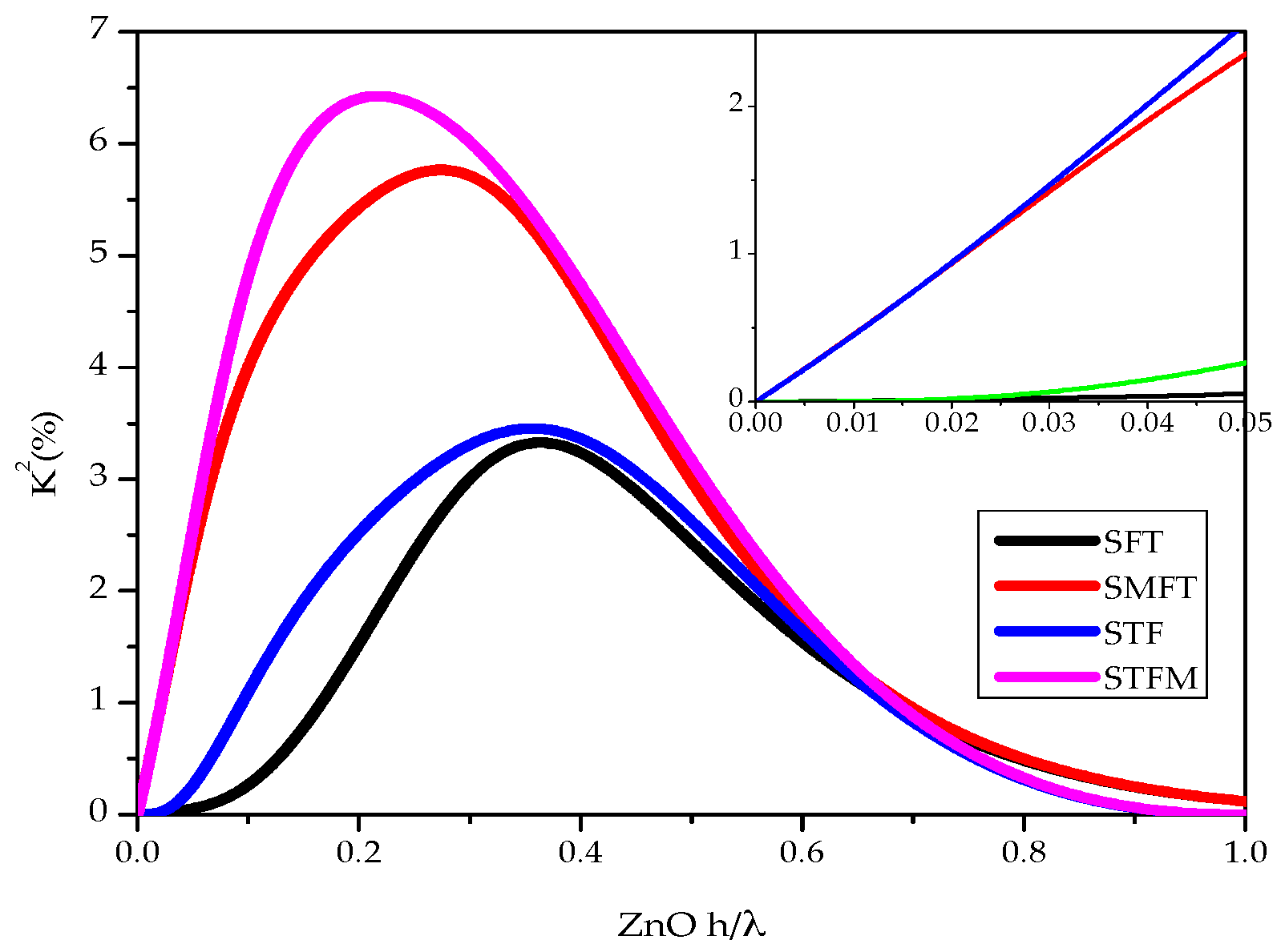
2.2.3. The Coupling Coefficient Dispersion Curves
3. Lamb Wave Sensors
3.1. Gravimetric Sensor
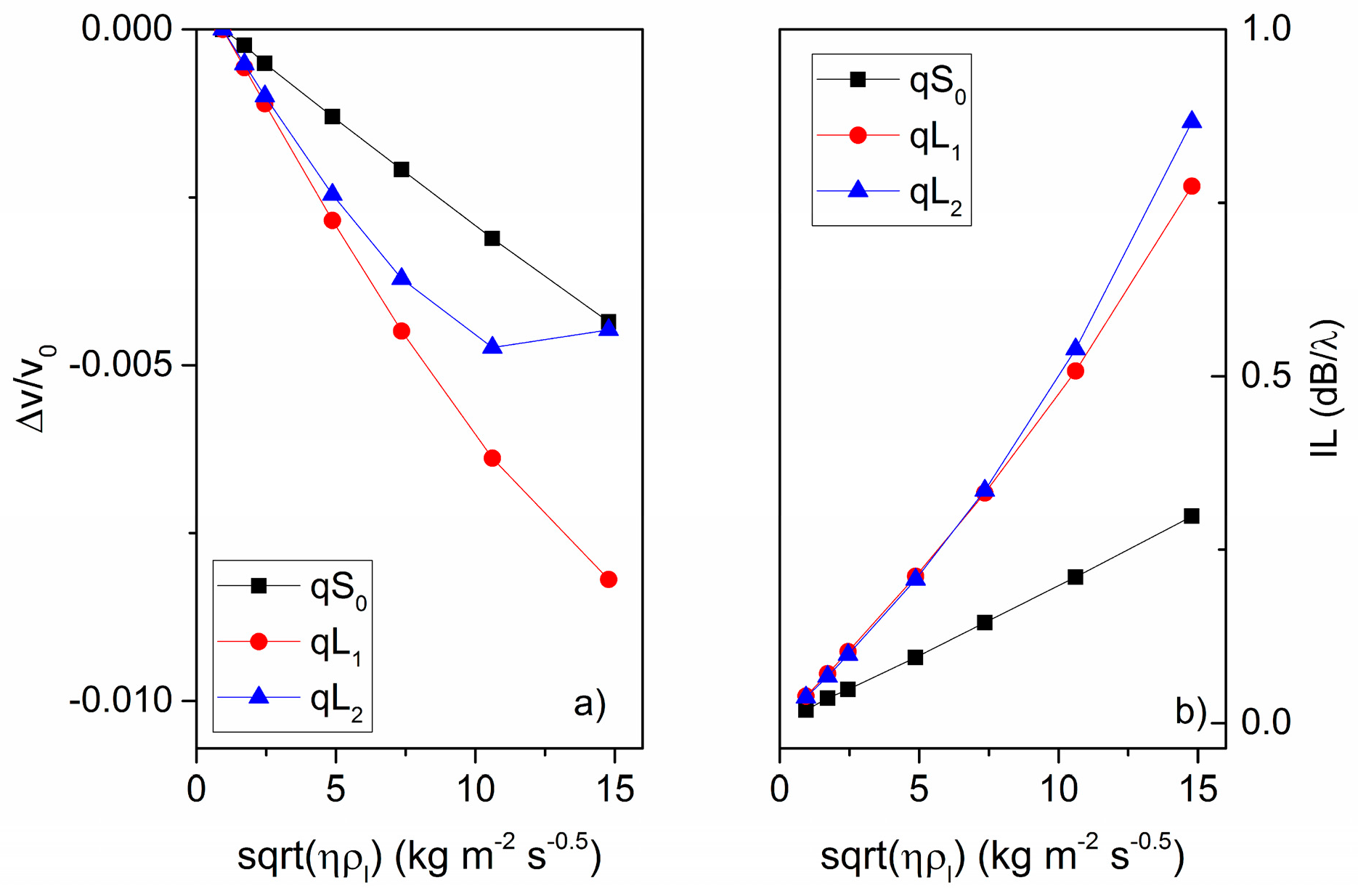
3.2. Viscosity Sensor
4. Conclusions
Acknowledgments
Author Contributions
Conflicts of Interest
References
- Viktorov, I.A. Rayleigh and Lamb Waves: Physical Theory and Applications; Plenum Press: New York, NY, USA, 1967. [Google Scholar]
- Rose, J.L. Ultrasonic Guided Waves in Solid Media; Cambridge University Press: Cambridge, UK, 2014. [Google Scholar]
- Caliendo, C. Theoretical investigation of Lamb wave A0 mode in thin SiC/AlN membranes for sensing application in liquid media. Sens. Actuators B Chem. 2013, 179, 287–292. [Google Scholar] [CrossRef]
- Sato, T.; Okajima, H.; Kashiwase, Y.; Motegi, R.; Nakajima, H. Shear Horizontal Acoustic Plate Mode Viscosity Sensor. Jpn. J. Appl. Phys. 1993, 32, 2392. [Google Scholar] [CrossRef]
- Caliendo, C.; D’Amico, A.; Verardi, P.; Verona, E. K+ detection using shear horizontal acoustic modes. In Proceedings of the Ultrasonics Symposium, Honolulu, HI, USA, 4–7 December 1990; pp. 383–387. [Google Scholar]
- Hoummady, M.; Bastien, F. Observation of liquid-solid phase transitions using a shear horizontal acoustic plate mode sensor. J. Appl. Phys. 1991, 70, 4629. [Google Scholar] [CrossRef]
- Anisimkin, I.V. A novel Lamb-mode liquid sensor array. In Proceedings of the IEEE Symposium on Ultrasonics, Honolulu, HI, USA, 5–8 October 2003. [Google Scholar]
- Caliendo, C. Longitudinal Modes along Thin Piezoelectric Waveguides for Liquid Sensing Applications. Sensors 2015, 15, 12841–12856. [Google Scholar] [CrossRef] [PubMed]
- Adler, E.L.; Nassar, A.A. Plate modes in piezoelectric multilayered structures. Rev. Phys. Appl. 1985, 20, 311–317. [Google Scholar] [CrossRef]
- Lin, C.; Chen, Y.; Pisano, A.P. Theoretical investigation of Lamb wave characteristics in AlN/3C-SiC composite membranes. Appl. Phys. Lett. 2010, 97, 193506. [Google Scholar] [CrossRef]
- Lin, C.-M.; Chen, Y.-Y.; Felmetsger, V.V.; Senesky, D.G.; Pisano, A.P. AlN/3C-SiC composite plate enabling high-frequency and high-Q micromechanical resonators. Adv. Mater. 2012, 24, 2722–2727. [Google Scholar] [CrossRef] [PubMed]
- Lin, C.; Chen, Y.; Felmetsger, V.V.; Senesky, D.G.; Pisano, A.P. Dispersion characteristics of high-order lamb wave modes in an AlN/3C-SiC layered plate. In Proceedings of the 2012 IEEE International Ultrasonics Symposium (IUS), Dresden, Germany, 7–10 October 2012. [Google Scholar]
- Caliendo, C. Theoretical investigation of high velocity, temperature compensated Rayleigh waves along AlN/SiC substrates for high sensitivity mass sensors. Appl. Phys. Lett. 2012, 100, 021905. [Google Scholar] [CrossRef]
- Hickernell, F.S.; Hickernell, T.S. Surface Acoustic Wave Characterization of PECVD Films on Gallium Arsenide. IEEE Trans. Ultrason. Ferroelectr. Freq. Control 1995, 42. [Google Scholar] [CrossRef]
- Vashishta, P.; Kalia, R.K.; Nakano, A. Interaction potential for silicon carbide: A molecular dynamics study of elastic constants and vibrational density of states for crystalline and amorphous silicon carbide. J. Appl. Phys. 2007, 101, 103515. [Google Scholar] [CrossRef]
- Nalwa, H.S. Silicon-Based Material and Devices, Properties and Devices, Vol. 1 Materials and Processing, Chapter 1, Optical, Structural and Electrical Properties of Amorphous Silicon Carbide Films; Academic Press: Cambridge, MA, USA, 2001. [Google Scholar]
- Zamani, H.; Lee, S.W.; Avishai, A.; Zorman, C.A.; Sankaran, R.M.; Feng, P.X.L. Focused Ion Beam (FIB) Nanomachining of Silicon Carbide (SiC) Stencil Masks for Nanoscale Patterning. Mater. Sci. Forum 2012, 717–720, 889–892. [Google Scholar] [CrossRef]
- Caliendo, C.; Castro, F. Advanced Bulk and Thin Film Materials for Harsh Environment MEMS Applications. In Anti-Abrasive Nanocoatings: Current and Future Applications; Aliofkhazraei, M., Ed.; Woodhead Publishing Reviews, Mechanical Engineering; Woodhead Publishing: Sawston, UK, 2015. [Google Scholar]
- Slobodnik, A.J., Jr.; Conway, E.D.; Delmonico, R.T. Air Force Cambridge Research Laboratories; Report No. AFCRL-TR-73-0597; U.S. Department of Commerce: Washington, DC, USA, 1973.
- Pavlakovic, B.N.; Lowe, M.J.S.; Alleyne, D.N.; Cawley, P. Dispesre: A general purpose program for creating dispersion curves. In Review of Progress in Quantitative NDE; Thompson, D.O., Chimenti, D.E., Eds.; Plenum Press: New York, NY, USA, 1997; Volume 16, pp. 185–192. [Google Scholar]
- Slie, W.M.; Donfor, A.R., Jr.; Litovitz, T.A. Ultrasonic Shear and Longitudinal Measurements in Aqueous Glycerol. J. Chem. Phys. 1966, 44, 3712. [Google Scholar] [CrossRef]
- Lin, C.-M.; Yantchev, V.; Zou, J.; Chen, Y.-Y.; Pisano, A.P. Micromachined one-port aluminum nitride Lamb wave resonators utilizing the lowest-order symmetric mode. J. Microelectromech. Syst. 2014, 23, 78–91. [Google Scholar] [CrossRef]
- Powell, D.A. Modelling of Layered Surface Acoustic Wave Resonators for Liquid Media Sensing Applications. Ph.D. Thesis, School of Electrical and Computer Engineering Science, Engineering and Technology Portfolio, RMIT University, Melbourne, Australia, May 2006. [Google Scholar]
- Ballantine, D.S.; White, R.M.; Martin, S.J.; Ricco, A.J.; Zellers, E.T.; Fye, G.C.; Wohltjen, H. Acoustic Wave Sensors: Theory, Design, & Physico-Chemical Applications; Academic Press: Cambridge, MA, USA, 1997. [Google Scholar]
- Wang, J.; Chen, W. Piezoelectricity, Acoustic Waves and Device Applications: Proceedings of the 2006 Symposium, Zhejiang University, China, 14–16 December 2006; World Scientific: Singapore, 2007; pp. 205–209. [Google Scholar]


| Mode /K2 (%) | Coupling Configuration | |||
|---|---|---|---|---|
| SFT | SMFT | STF | STFM | |
| qS0 | 0.054 | 2.35 | 0.26 | 2.56 |
| qL1 | 0.08 | 0.54 | 0.33 | 0.79 |
| qL2 | 0.15 | 0.20 | 0.084 | 0.13 |
© 2017 by the authors. Licensee MDPI, Basel, Switzerland. This article is an open access article distributed under the terms and conditions of the Creative Commons Attribution (CC BY) license (http://creativecommons.org/licenses/by/4.0/).
Share and Cite
Caliendo, C.; Hamidullah, M.; Laidoudi, F. Amorphous SiC/c-ZnO-Based Quasi-Lamb Mode Sensor for Liquid Environments. Sensors 2017, 17, 1209. https://doi.org/10.3390/s17061209
Caliendo C, Hamidullah M, Laidoudi F. Amorphous SiC/c-ZnO-Based Quasi-Lamb Mode Sensor for Liquid Environments. Sensors. 2017; 17(6):1209. https://doi.org/10.3390/s17061209
Chicago/Turabian StyleCaliendo, Cinzia, Muhammad Hamidullah, and Farouk Laidoudi. 2017. "Amorphous SiC/c-ZnO-Based Quasi-Lamb Mode Sensor for Liquid Environments" Sensors 17, no. 6: 1209. https://doi.org/10.3390/s17061209
APA StyleCaliendo, C., Hamidullah, M., & Laidoudi, F. (2017). Amorphous SiC/c-ZnO-Based Quasi-Lamb Mode Sensor for Liquid Environments. Sensors, 17(6), 1209. https://doi.org/10.3390/s17061209