Article

Theoretical Study of Monolayer and Double-Layer Waveguide Love Wave Sensors for Achieving High Sensitivity

School of Mechanical Engineering, Nanjing University of Science and Technology, Nanjing 210094, China
*
Authors to whom correspondence should be addressed.
Sensors 2017, 17(3), 653; https://doi.org/10.3390/s17030653
Submission received: 2 February 2017 / Revised: 19 March 2017 / Accepted: 20 March 2017 / Published: 22 March 2017
(This article belongs to the Special Issue Acoustic Wave Resonator-Based Sensors)

Abstract

:
Love wave sensors have been widely used for sensing applications. In this work, we introduce the theoretical analysis of the monolayer and double-layer waveguide Love wave sensors. The velocity, particle displacement and energy distribution of Love waves were analyzed. Using the variations of the energy repartition, the sensitivity coefficients of Love wave sensors were calculated. To achieve a higher sensitivity coefficient, a thin gold layer was added as the second waveguide on top of the silicon dioxide (SiO2) waveguide–based, 36 degree–rotated, Y-cut, X-propagating lithium tantalate (36° YX LiTaO3) Love wave sensor. The Love wave velocity was significantly reduced by the added gold layer, and the flow of wave energy into the waveguide layer from the substrate was enhanced. By using the double-layer structure, almost a 72-fold enhancement in the sensitivity coefficient was achieved compared to the monolayer structure. Additionally, the thickness of the SiO2 layer was also reduced with the application of the gold layer, resulting in easier device fabrication. This study allows for the possibility of designing and realizing robust Love wave sensors with high sensitivity and a low limit of detection.

1. Introduction

Surface acoustic wave (SAW) devices have been used in various sensing applications such as temperature [1], stress [2], gas [3], chemical and biological sensing [4] fields. The SAW sensor is a piezoelectric mass sensor which is sensitive to the mass loading on its surface [5]. The mass loading can influence the propagation of acoustic waves, as detected from changes in the velocity, phase, and amplitude. Thus, SAW sensors can be utilized to detect biomarkers which can be captured specifically by the modified surface. Owing to their high sensitivity, low cost, ease of integration with electronic circuits and possibility of real-time monitoring, SAW biosensors have been widely used for the bio-detection of proteins, DNA and cells [6,7,8]. With these advantages, SAW biosensors have a great potential in clinical diagnosis, especially in point-of-care testing for portable sensing applications.
There are various types of SAWs, such as the Rayleigh wave [9], the surface skimming bulk wave (SSBW) [10], and the Love wave [11]. The Rayleigh wave, which propagates with an elliptical particle displacement, presents a vibration component in the surface normal direction. The damping of the water causes a high energy loss leaking into the liquid, and limits the application in liquid detection. SSBW is a kind of shear horizontal SAW (SH-SAW), which can be used for liquid detection. However, its waves are not confined to the surface, resulting in a high insertion loss and a low mass loading sensitivity.
The Love wave sensor, also named the guided SH-SAW sensor, is a favored device for liquid phase applications [12,13,14]. This device has a low velocity waveguide layer on the substrate. The waveguide layer reduces power consumption and increases sensitivity by confining most of the wave energy in this layer.
Silicon dioxide (SiO2) is a commonly used waveguide material for the Love wave sensors due to its chemical stability, in comparison to other polymer materials such as polymethylmethacrylate (PMMA) and positive photoresists [11,15,16,17]. Among various piezocrystals, 36 degree–rotated Y-cut X-propagating lithium tantalate (36° YX LiTaO3) shows a high electromechanical coupling coefficient (K2) and low power consumption [16,18]. The propagation of the acoustic waves in 36° YX-LiTaO3 is shear horizontal, showing great potential in liquid detection [19]. When a SiO2 layer as the waveguide is added, the waves transform to Love waves, which are more sensitive to the mass loading.
According to the literature [16,20,21,22], the wavelengths of the 36° YX-LiTaO3 Love wave sensors usually range from 20 μm to 40 μm, with center frequencies from about 210–105 MHz. Although a higher center frequency can increase the mass loading sensitivity, it can also cause difficulties in circuit design and testing, thereby creating a high noise level. Thus, the most widely used method to increase the sensitivity is to optimize the waveguide layer thickness. However, the optimal waveguide thickness corresponding to the highest sensitivity is much larger than that having the lowest insertion loss [11]. High insertion loss decreases the signal-to-noise ratio, and thus worsens the limit of detection. It also suffers from a disadvantage to the miniaturization of portable detection systems, because of the high power consumption.
Double-layer waveguide presents an effective method to improve the performance of Love wave sensors [23,24]. By adding an ultra-low-velocity layer on the SiO2 waveguide layer, the Love wave velocity could be further decreased and more wave energy may be trapped in the waveguide layer. Thus, the Love wave sensor can be made more sensitive to mass loading on the surface. Table 1 shows the important parameters of SiO2, gold (Au) and 36° YX LiTaO3. Compared with SiO2, Au has a much lower velocity and the potential to be used as the second waveguide layer of Love wave sensors. Besides, it also shows stable physicochemical properties and biocompatibility for biomolecule self-assembly [25].
In this work, a thin Au layer is added as the second waveguide layer on top of the SiO2-based 36° YX LiTaO3 Love wave sensor in order to achieve a higher sensitivity coefficient and a thinner optimal waveguide thickness. We have theoretically analyzed both the monolayer and double-layer waveguide Love wave sensors. The methods to solve the displacements, energy distributions and sensitivity coefficients of these two types of Love wave sensors are discussed. The Love wave velocity and energy distributions are calculated and the optimal thicknesses of waveguide layers are also obtained.

2. Theoretical Analysis

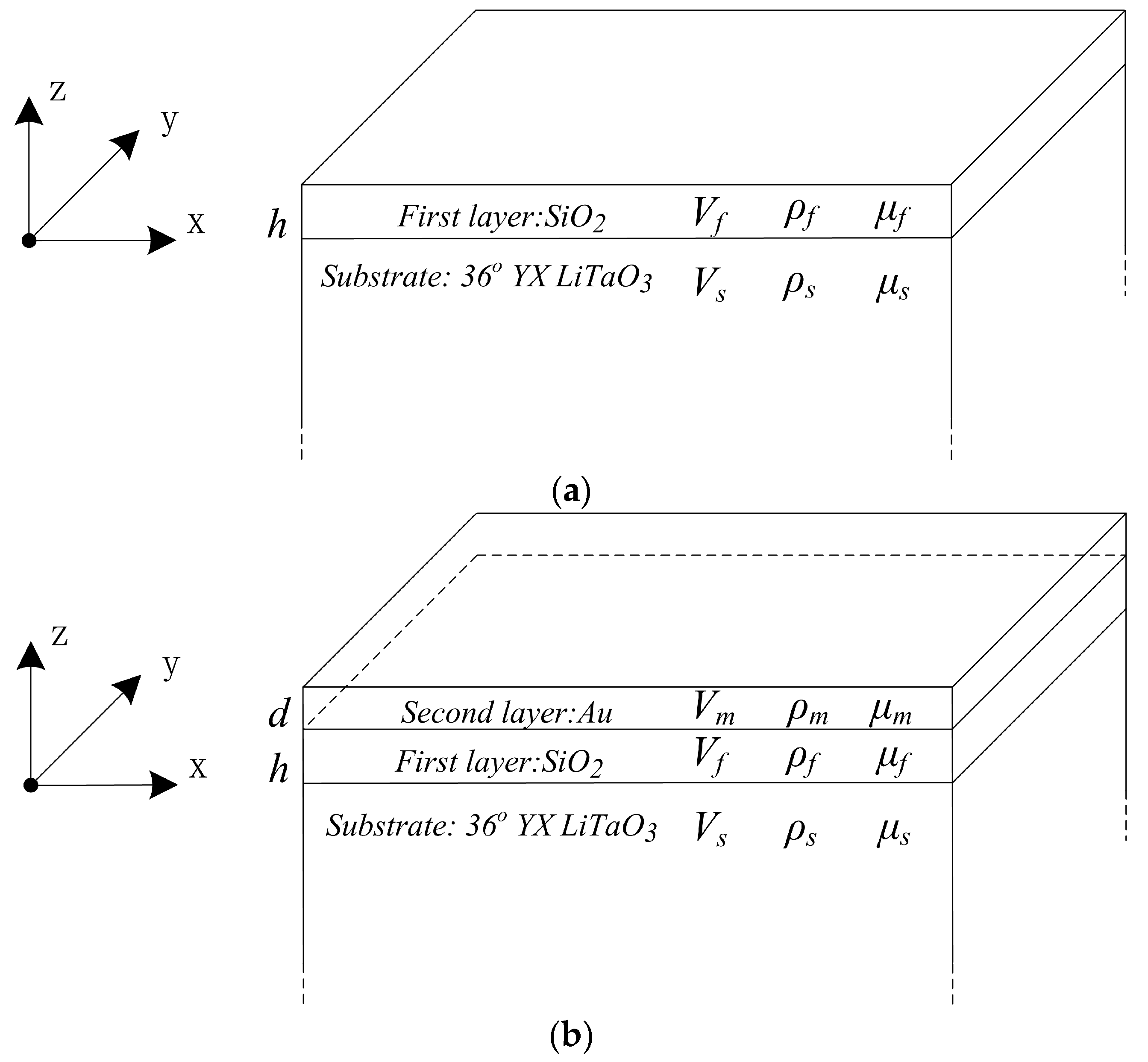
2.1. Love Wave Propagation Equation

As the thickness of the substrate is much larger than that of the waveguide layer, the Love wave device is generally regarded as a semi-infinite half-space. Figure 1 shows the diagrams of the monolayer and double-layer waveguide Love wave sensor structures. The coordinate system is built up, and the original point is located on the boundary surface of the substrate and waveguide layer.
The x-axis is the longitudinal direction that the Love wave is propagating along; the y-axis is the shear horizontal direction of the particle vibration; and the z-axis is the normal direction of the device surface. Because the particle displacement is shear horizontally polarized, the piezoelectric substrate can be simplified as an isotropic or highly symmetrical anisotropic material.
The symbols h and d are the thicknesses of the first (SiO2) and second (Au) waveguide layers. The symbols V S , V f and V m represent the shear velocities, while ρ S , ρ f and ρ m stand for the densities of the respective material. The shear moduli of the substrate (36° YX LiTaO3), first (SiO2) and second (Au) waveguide layers are represented by μ S , μ f and μ m , respectively.
The Love wave propagation equations of the double-layer structure can be defined as shown in Equations (1)–(3). The monolayer Love wave propagation equations are comprised of Equations (1) and (2) [26,27].
( 2 x 2 + 2 z 2 + ω 2 V f 2 ) u y f = 0
( 2 x 2 + 2 z 2 + ω 2 V S 2 ) u y S = 0
( 2 x 2 + 2 z 2 + ω 2 V m 2 ) u y m = 0
The symbol ω is the radian frequency of the Love wave; u y f , u y S and u y m are the particle displacements along the y-axis on x-z plane in first waveguide layer, substrate and second waveguide layer, respectively, and their general solution forms can be defined as below.
u y f = ( A e i β f z + B e i β f z ) e i ( k x ω t ) u y S = ( C e β S z + D e β S z ) e i ( k x ω t ) u y m = ( E e i β m z + F e i β m z ) e i ( k x ω t )   where   β f = ω 2 V f 2 k 2 β S = k 2 ω 2 V S 2 β m = ω 2 V m 2 k 2
The A, B, C, D, E and F are the coefficients to be solved, and k is the wave number.

2.2. Boundary Condition

The boundary conditions can be classified into two types. The first one is at the boundary between the two different materials. Both the particle displacements and stress are equal at the boundaries. The second one is the stress which is equal to zero at both the surface and bottom of the device. Thus, the boundary conditions for the monolayer and double-layer Love wave sensors can be defined as Equations (5)–(8) [26,27].
u y S = u y f μ S u y S z = μ f u y f z   when   z = 0
u y f z = 0   ( monolayer )   u y m = u y f μ m u y m z = μ f u y f z   ( double-layer )   when   z = h
u y m z = 0   ( double-layer )   when   z = h + d
μ S u y S z = 0   when   z

2.3. Dispersion Equation

Substituting the boundary conditions into the particle displacement equations, the system of the homogeneous linear equations of the monolayer structure can be obtained as shown in Equation (9).
A + B D = 0 A + B + i ξ D = 0 A e i 2 β S h B = 0   where   ξ = μ S β S μ f β f
The condition for this system having nontrivial solutions is that the value of its coefficient determinant is zero. Using Euler's formula, the Love wave dispersion equation can be obtained as Equation (10). This dispersion equation shows the relationship among the Love wave velocity, the waveguide layer thickness and the material parameters of the substrate and waveguide layers.
tan ( β S h ) = ξ
Similarly, the coefficient matrix of the double-layer structure is described as:
Γ = ( 1 1 1 0 0 1 1 i ξ 0 0 e i β f h e i β f h 0 e i β m h e i β m h e i β f h e i β f h 0 ξ m e i β m h ξ m e i β m h 0 0 0 e i β m ( h + d ) e i β m ( h + d ) )
When the determinant | Γ | = 0 , the dispersion equation of the double-layer Love wave sensor can be obtained as Equation (12). It is indicated that the Love wave velocity of the double-layer substrate is also affected by the thickness and material parameters of the second waveguide layer.
ξ m tan β m d = tan β f h ξ ξ tan β f h + 1   where   ξ m = μ m β m μ f β f

2.4. Particle Displacement and Wave Energy

By solving the fundamental solutions of the homogeneous linear equations system, the normalized displacements of the monolayer structure can be calculated by Equation (13).
u y f = cos ( β f ( z h ) ) cos ( β f h ) e i ( k x ω t ) u y S = e β S z e i ( k x ω t )
The normalized displacements of the double-layer structure can be described as:
u y f = ( cos β f z + ξ sin β f z ) e i ( k x ω t ) u y S = e β S z e i ( k x ω t ) u y m = a cos β m ( z h d ) cos β m d e i ( k x ω t )   where   a = cos β f h + ξ sin β f h
The total time-averaged kinetic energy in the substrate ( W k S ), the first waveguide layer ( W k f ) and the second waveguide layer ( W k m ) can be calculated as [26]:
W k S = 1 4 ω 2 ρ S 0 | u y S | 2 d z W k f = 1 4 ω 2 ρ f 0 h | u y f | 2 d z W k m = 1 4 ω 2 ρ m h d | u y m | 2 d z
Substituting the particle displacements of Equations (13) and (14) into Equation (15), respectively, the wave energy in the monolayer Equation (16) and double-layer Equation (17) Love wave sensor can be calculated. Further, | A | 2 is the normalized coefficient.
W k S = 1 8 ω 2 | A | 2 ρ S / β S W k f = 1 8 ω 2 ρ f | A | 2 ( β f h + sin ( β f h ) cos ( β f h ) ) / ( β f cos 2 ( β f h ) )
W k S = 1 8 ω 2 | A | 2 ρ S / β S W k f = 1 8 ω 2 ρ f | A | 2 ( ( 1 + ξ 2 ) β f h + ( 1 ξ 2 ) sin ( β f h ) cos ( β f h ) ξ ( cos ( 2 β f h ) 1 ) ) / β f W k m = 1 8 ω 2 ρ m a 2 | A | 2 ( β m d + sin ( β m d ) cos ( β m d ) ) / ( β m cos 2 ( β m d ) )

2.5. Sensitivity of the Love Wave Sensor

The sensitivity of the Love wave sensor can be calculated based on the perturbation theory [5,28]. The mass loading on the surface can be considered as a small perturbation causing a small change of the kinetic energy, which can be obtained through the particle displacements and energy transport [26]. It is known that with the increasing waveguide layer thickness, more energy is present in the waveguide layer than in the substrate. It can be approximated that this is similar to the variation of the energy repartition in the structure when a mass loading film attaches to the surface [29]. The mass loading (density ρ l , thickness Δ ε ) is a very thin film in comparison to the waveguide layer, and thus it can be considered as a slight thickness increase of the waveguide layer, which can be considered as ρ l Δ ε = ρ f Δ h . Hence, the mass loading sensitivity can be estimated by the energy variation in the substrate to the mass modification via Equation (18).
S m = 1 W lim Δ m l 0 Δ W Δ m l 1 ρ f λ W d W d α = K ρ f λ
The normalized thickness is α = h / λ , and λ is the wavelength of the Love wave. With the same method for the sensitivity calculation of the monolayer Love wave sensor, the mass loading sensitivity of the double-layer Love wave sensor can be described as:
S m 1 ρ m λ W d W d α = K ρ m λ
As the density and the wavelength are constant coefficients for certain Love wave devices, the non-dimensional factor K, named the sensitivity coefficient, can be used to describe the sensitivity of different devices with various wavelengths.

3. Results and Discussion

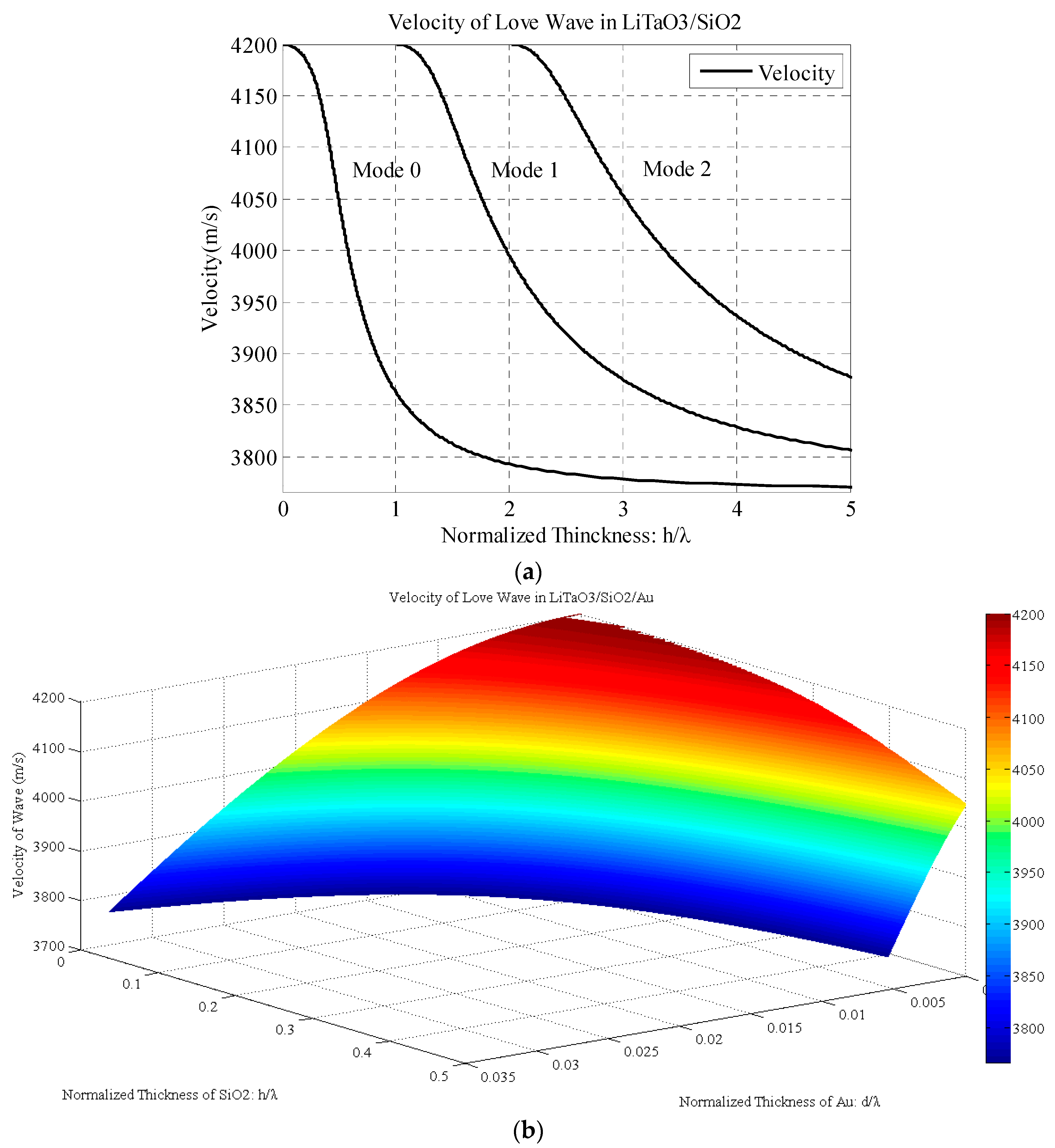
3.1. Results of Love Wave Velocity

As the dispersion equations (Equations (10) and (12)) are implicit functions and cannot be calculated directly, we calculated them using MATLAB. The monolayer Love wave velocity is shown in Figure 2a. It is clearly indicated that increasing the layer thickness decreases the velocity of the Love wave from the shear velocity in the substrate to that in the waveguide layer. The multi-modes of the Love wave are owing to the multiple solutions of the trigonometric function. Generally, the thickness of the waveguide is very thin compared with the wavelength, and thus only the 0-mode should be considered.
The velocity of the Love wave in the LiTaO3/SiO2/Au structure is shown in Figure 2b. It is indicated that the velocity decreases from the velocity of the LiTaO3 substrate when the thicknesses of both the SiO2 and Au waveguide layer are increasing. The contour plot shows that even when the SiO2 or Au layer thickness is constant, the velocity of the Love wave decreases with the other layer thickness increasing. Owing to the lower velocity, the Love wave velocity decreases much faster in the Au layer direction than in the SiO2 direction.

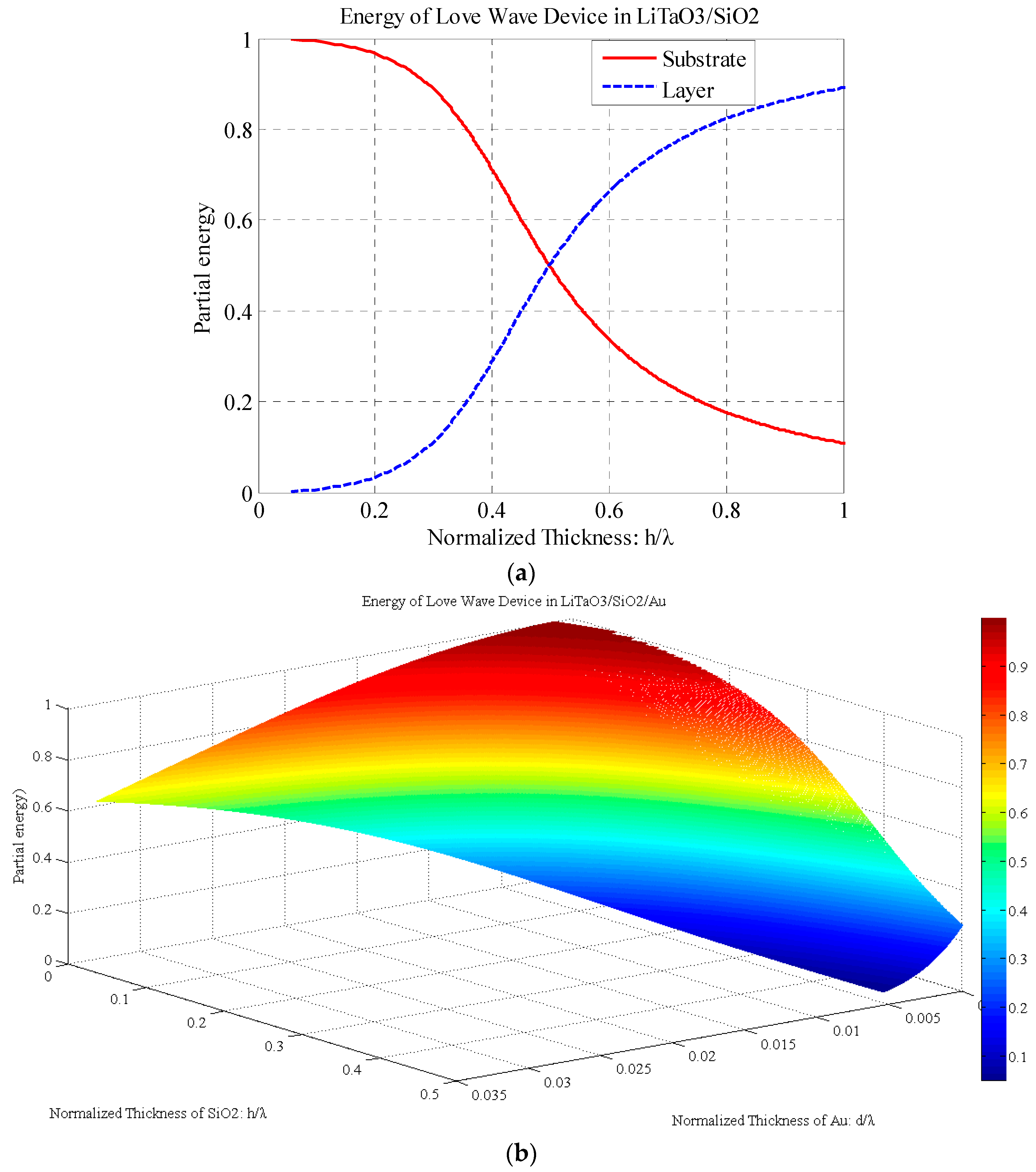
3.2. Results of Love Wave Energy

After obtaining the functional relationship between the velocity and waveguide layer thickness, the total time-averaged kinetic energy in the substrate and waveguide layers can be solved according to Equations (16) and (17). As seen explicitly in Figure 3a, the partial energy in the substrate and that in the waveguide layer varies with the thickness; however, the total energy of the Love wave is assumed to be constant. At the beginning, most of the wave energy propagates in the substrate. With the thickness of the waveguide layer increases, the energy moves from the substrate to the waveguide layer, leading to highly centralized energy in the waveguide layer.
Figure 3b shows the partial energy proportion in the LiTaO3 substrate. The energy in the substrate decreases with both the SiO2 and Au waveguide layer thickness increasing. It is indicated that more wave energy moves from the substrate to the waveguide layer. The decreasing rates in the SiO2 and Au layer directions are different because of their different material parameters.

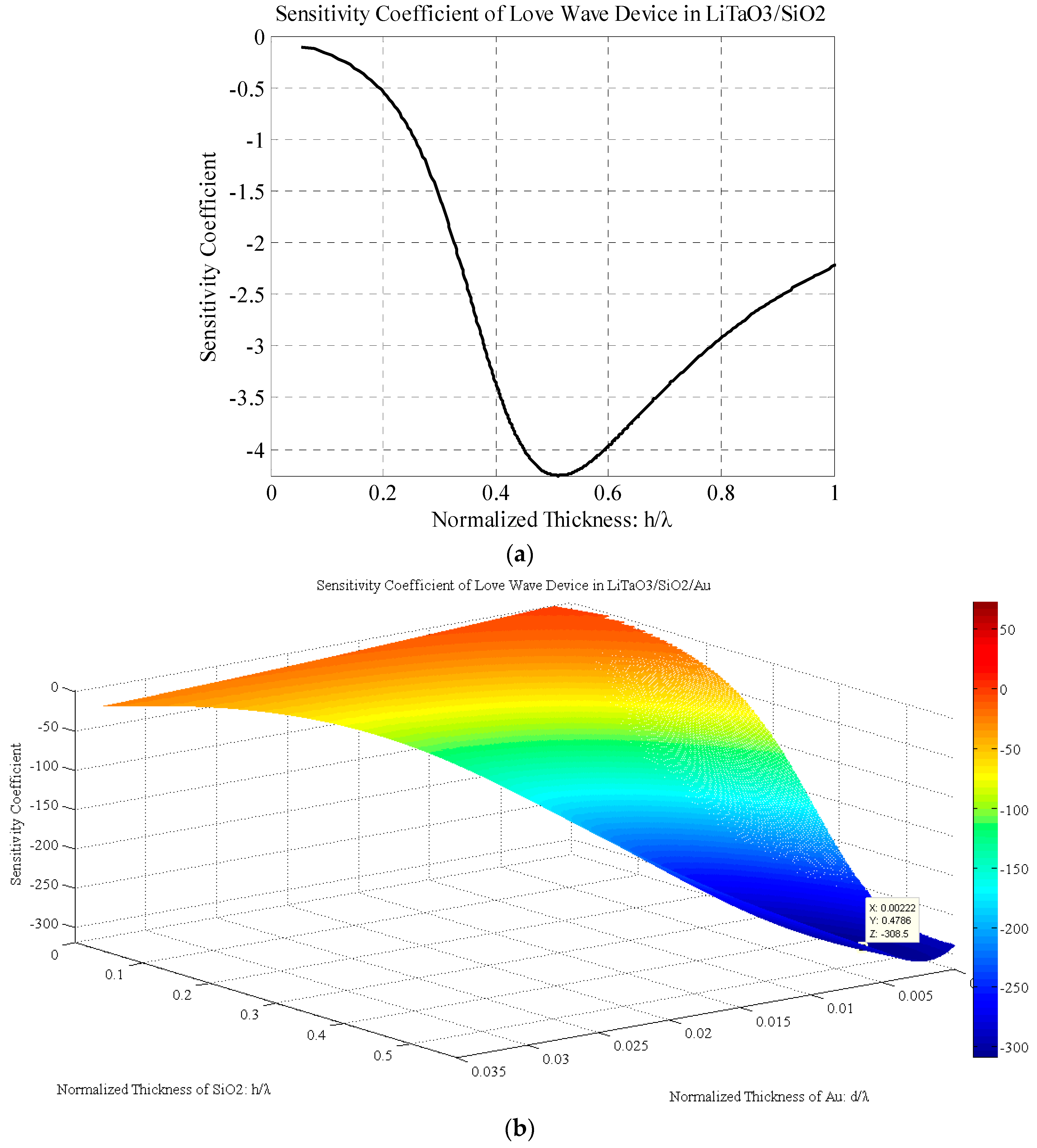
3.3. Results of Love Wave Sensors’ Sensitivity

The sensitivity coefficients of the monolayer and double-layer structures can be calculated via the energy variation in the substrate. The sensitivity coefficient of the LiTaO3/SiO2 Love wave sensor is shown in Figure 4a. Initially the absolute value of the sensitivity coefficient increases when the SiO2 layer thickness increases, and it reaches the optimal value (K = −4.25) at the normalized thickness of 0.51. Then the sensitivity coefficient decreases with the layer thickness increasing.
As shown in Figure 4b, the sensitivity coefficient of the LiTaO3/SiO2/Au Love wave sensor reaches an optimal value (K = −308.4656) when the normalized thicknesses of the SiO2 and Au layers are at 0.4786 and 0.0022, respectively. The 3D contour plot reveals the higher sensitivity coefficient of the LiTaO3/SiO2/Au structure compared to that of the monolayer structure. By using the SiO2/Au as a double-layer waveguide, the sensitivity coefficient of the Love wave sensor is enhanced about 72-fold.
Comparing the monolayer and double-layer Love wave sensors, the optimal thickness condition of the SiO2 layer is decreased by the added Au layer. Using 20 µm as the wavelength of the Love wave, for example, the optimal SiO2 thickness is found to be 10.2 µm for the monolayer Love wave sensor and 9.57 µm for the double-layer one. The optimal thickness of Au is only about 44 nm, and this thin layer is very easy to be fabricated using Au deposition. Even for the decreased SiO2 thickness layer range of about 1–4 µm, the sensitivity coefficient of the double-layer sensor is still higher than that of the monolayer one. For example, the sensitivity coefficient is equal to −100 when the SiO2 layer and Au layer are 4 µm and 74 nm, respectively. As a result, this leads to a much easier fabrication and a lower insertion loss compared with the monolayer sensors with a SiO2 layer thicker than 10 µm.

4. Conclusions

In this work, the theoretical analysis of the monolayer and double-layer waveguide Love wave sensors is presented. The variations of the energy repartition in the structure are utilized to calculate the sensitivity coefficients of the Love wave sensors. It is indicated that the optimized normalized thickness of the SiO2 layer for the monolayer 36° YX LiTaO3 substrate is 0.51. A 72-fold enhancement of the sensitivity coefficient is achieved by using a SiO2/Au double-layer structure, when the optimal normalized thicknesses are 0.4786 and 0.0022, respectively. In addition, the thickness of the SiO2 layer to achieve the same and an even higher sensitivity coefficient as that of the monolayer sensor is significantly reduced with the help of the thin gold layer. Our results provide guidelines for the design and fabrication of Love wave sensors to achieve a high sensitivity and to reduce the device fabrication difficulties.

Acknowledgments

This work was financially supported by the National Science Foundation (No. 61371039, 21105048) and the China Postdoctoral Science Foundation funded project (No. 2012T50475).

Author Contributions

All the authors made significant contributions to the work. S.L., Y.W., C.F. and Y.S. conceived the study. S.L. simulated and analyzed the data. Y.W., C.F. and Y.S. provided advice for the preparation and revision of the paper. S.L. wrote the paper.

Conflicts of Interest

The authors declare no conflict of interest.

References

  1. Buff, W.; Klett, S.; Rusko, M.; Ehrenpfordt, J.; Goroli, M. Passive remote sensing for temperature and pressure using SAW resonator devices. IEEE Trans. Ultrason. Ferroelectr. Freq. Control 1998, 45, 1388–1392. [Google Scholar] [CrossRef]
  2. Scherr, H.; Scholl, G.; Seifert, F.; Weigel, R. Quartz pressure sensor based on SAW reflective delay line. In Proceedings of the Ultrasonics Symposium, San Antonio, TX, USA, 3–6 November 1996; pp. 347–350.
  3. Afzal, A.; Iqbal, N.; Mujahid, A.; Schirhagl, R. Advanced vapor recognition materials for selective and fast responsive surface acoustic wave sensors: A review. Anal. Chim. Acta 2013, 787, 36–49. [Google Scholar] [CrossRef] [PubMed]
  4. Länge, K.; Rapp, B.E.; Rapp, M. Surface acoustic wave biosensors: A review. Anal. Bioanal. Chem. 2008, 391, 1509–1519. [Google Scholar] [CrossRef] [PubMed]
  5. Ballantine, D.S., Jr.; White, R.M.; Martin, S.J.; Ricco, A.J.; Zellers, E.T.; Frye, G.C.; Wohltjen, H. Acoustic Wave Sensors: Theory, Design, & Physico-Chemical Applications; Academic Press: San Diego, CA, USA, 1996. [Google Scholar]
  6. Länge, K.; Bender, F.; Voigt, A.; Gao, H.; Rapp, M. A surface acoustic wave iosensor concept with low flow cell volumes for label-free detection. Anal. Chem. 2003, 75, 5561–5566. [Google Scholar] [CrossRef] [PubMed]
  7. Hur, Y.; Han, J.; Seon, J.; Pak, Y.E.; Roh, Y. Development of an SH-SAW sensor for the detection of DNA hybridization. Sens. Actuators A Phys. 2005, 120, 462–467. [Google Scholar] [CrossRef]
  8. Feng, C.T.; Cheng, C.J.; Atashbar, M.Z. PMMA/64° YX-LiNbO3 guided SH-SAW based immunosensing system. In Proceedings of the Sensors IEEE, Limerick, Ireland, 28–31 October 2011; pp. 308–311.
  9. Wohltjen, H.; Dessy, R. Surface acoustic wave probe for chemical analysis. I. Introduction and instrument description. Anal. Chem. 1979, 51, 1458–1464. [Google Scholar] [CrossRef]
  10. Browning, T.; Lewis, M. A new class of quartz crystal oscillator controlled by surface-skimming bulk waves. In Proceedings of the 31st Annual Symposium on Frequency Control, Fort Monnount, NJ, USA, 1–3 June 1977; pp. 258–265.
  11. Du, J.; Harding, G.L.; Ogilvy, J.A.; Dencher, P.R.; Lake, M. A study of Love-wave acoustic sensors. Sens. Actuators A Phys. 1996, 56, 211–219. [Google Scholar] [CrossRef]
  12. Kovacs, G.; Lubking, G.; Vellekoop, M.; Venema, A. Love waves for (bio)-chemical sensing in liquids. In Proceedings of the Ultrasonics Symposium, Tucson, AZ, USA, 20–23 October 1992; pp. 281–285.
  13. Lee, S.; Kim, K.-B.; Kim, Y.-I. Love wave SAW biosensors for detection of antigen-antibody binding and comparison with SPR biosensor. Food Sci. Biotechnol. 2011, 20, 1413–1418. [Google Scholar] [CrossRef]
  14. Fertier, L.; Cretin, M.; Rolland, M.; Durand, J.-O.; Raehm, L.; Desmet, R.; Melnyk, O.; Zimmermann, C.; Déjous, C.; Rebière, D. Love wave immunosensor for antibody recognition using an innovative semicarbazide surface functionalization. Sens. Actuators B Chem. 2009, 140, 616–622. [Google Scholar] [CrossRef]
  15. Barié, N.; Wessa, T.; Bruns, M.; Rapp, M. Love waves in SiO2 layers on STW-resonators based on LiTaO3. Talanta 2004, 62, 71–79. [Google Scholar] [CrossRef]
  16. Branch, D.W.; Brozik, S.M. Low-level detection of a Bacillus anthracis simulant using Love-wave biosensors on 36° YX LiTaO3. Biosens. Bioelectron. 2004, 19, 849–859. [Google Scholar] [CrossRef] [PubMed]
  17. Gizeli, E.; Bender, F.; Rasmusson, A.; Saha, K.; Josse, F.; Cernosek, R. Sensitivity of the acoustic waveguide biosensor to protein binding as a function of the waveguide properties. Biosens. Bioelectron. 2003, 18, 1399–1406. [Google Scholar] [CrossRef]
  18. Richardson, M.; Sankaranarayanan, S.K.R.S.; Bhethanabotla, V.R. Low insertion loss and highly sensitive SH-SAW sensors based on 36° YX LiTaO3 through the incorporation of filled microcavities. IEEE Sens. J. 2015, 15, 787–796. [Google Scholar] [CrossRef]
  19. Moriizumi, T.; Unno, Y.; Shiokawa, S. New sensor in liquid using leaky SAW. In Proceedings of the Ultrasonics Symposium, Denver, CO, USA, 14–16 October 1987; pp. 579–582.
  20. Powell, D.A.; Kalantar-zadeh, K.; Ippolito, S.; Wlodarski, W. A layered SAW Device Based on ZnO/LiTaO3 for liquid media sensing applications. In Proceedings of the Ultrasonics Symposium, Munich, Germany, 8–11 October 2002; pp. 493–496.
  21. Zhang, F.; Li, S.; Cao, K.; Wang, P.; Su, Y.; Zhu, X.; Wan, Y. A microfluidic love-wave biosensing device for PSA detection based on an aptamer beacon probe. Sensors 2015, 15, 13839–13850. [Google Scholar] [CrossRef] [PubMed]
  22. Freudenberg, J.; Von Schickfus, M.; Hunklinger, S. A SAW immunosensor for operation in liquid using a SiO2 protective layer. Sens. Actuators B Chem. 2001, 76, 147–151. [Google Scholar] [CrossRef]
  23. Xu, F.; Wang, W.; Hou, J.; Liu, M. Temperature effects on the propagation characteristics of Love waves along multi-guide layers of SiO2/SU-8 on ST-90° X quartz. Sensors 2012, 12, 7337–7349. [Google Scholar] [CrossRef] [PubMed]
  24. Du, J.; Harding, G.L. A multilayer structure for Love-mode acoustic sensors. Sens. Actuators A Phys. 1998, 65, 152–159. [Google Scholar] [CrossRef]
  25. Dong, S.; Li, J. Self-assembled monolayers of thiols on gold electrodes for bioelectrochemistry and biosensors. Bioelectrochem. Bioenerg. 1997, 42, 7–13. [Google Scholar] [CrossRef]
  26. Seshadri, S.R. Energy transport velocity of surface elastic waves. J. Appl. Phys. 1983, 54, 1699–1703. [Google Scholar] [CrossRef]
  27. McHale, G.; Newton, M.I.; Martin, F. Theoretical mass sensitivity of Love wave and layer guided acoustic plate mode sensors. J. Appl. Phys. 2002, 91, 9701–9710. [Google Scholar] [CrossRef]
  28. Auld, B.A. Acoustic Fields and Waves in Solids, 2nd ed.; Krieger: Malabar, FL, USA, 1990. [Google Scholar]
  29. Francis, L. Investigation of Love Wave Sensors Optimisation for Biosensing Applications; Université Catholique De Louvain: Louvain-la-Neuve, Belgium, 2001. [Google Scholar]
Figure 1. Diagram of the Love wave sensor: (a) monolayer; (b) double-layer.
Sensors 17 00653 g001
Figure 2. Velocity of Love wave in (a) LiTaO3/SiO2 device; (b) LiTaO3/SiO2/Au device.
Sensors 17 00653 g002
Figure 3. (a) Partial energy of Love wave in LiTaO3/SiO2 device; (b) Partial energy of substrate in LiTaO3/SiO2/Au device.
Sensors 17 00653 g003
Figure 4. Sensitivity coefficient of Love wave devices: (a) LiTaO3/SiO2 structure; (b) LiTaO3/SiO2/Au structure.
Sensors 17 00653 g004
Table 1. Parameters of different materials.
MaterialsDensity (kg/m3)Shear Velocity (m/s)
SiO222003766
Au19,3001215
36° YX LiTaO374544200

