
A Hierarchical Framework Combining Motion and Feature Information for Infrared-Visible Video Registration

Abstract
:1. Introduction
- We propose a new registration framework based on CSS keypoints that improves the accuracy of global homography by combining feature and motion information.
- We propose a simple method to calculate the motion vectors of targets in coarse registration that transforms the scale and rotation estimation into an easy, homologous keypoint-matching problem.
- We calculate the normalized location (NL) descriptors and the histogram of edge orientation (HOE) descriptors to strictly match keypoints. Moreover, we count the matching directions of correspondences to eliminate mismatches.
2. Related Work
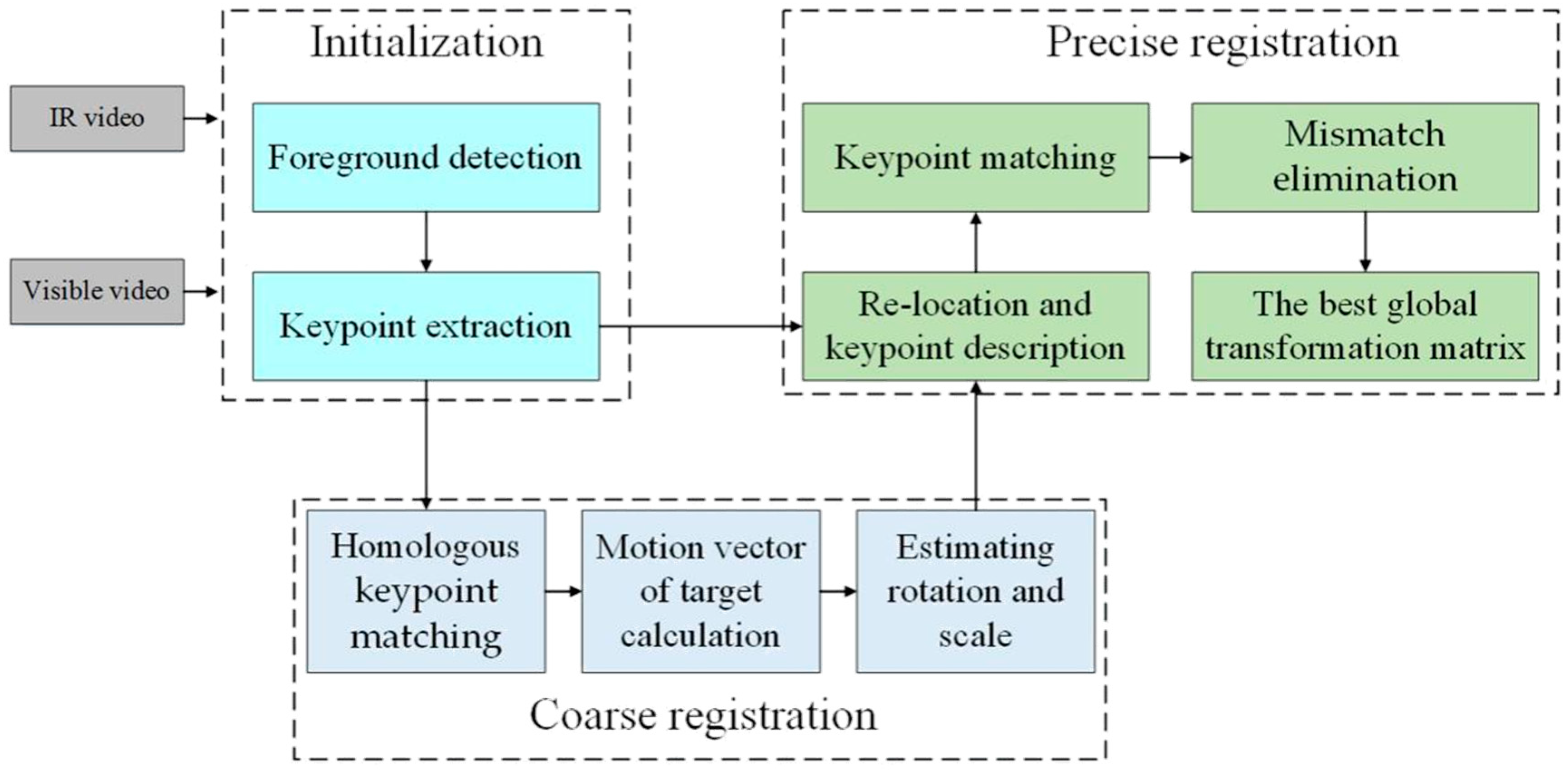
3. Registration Framework
3.1. Theory of the Proposed Framework
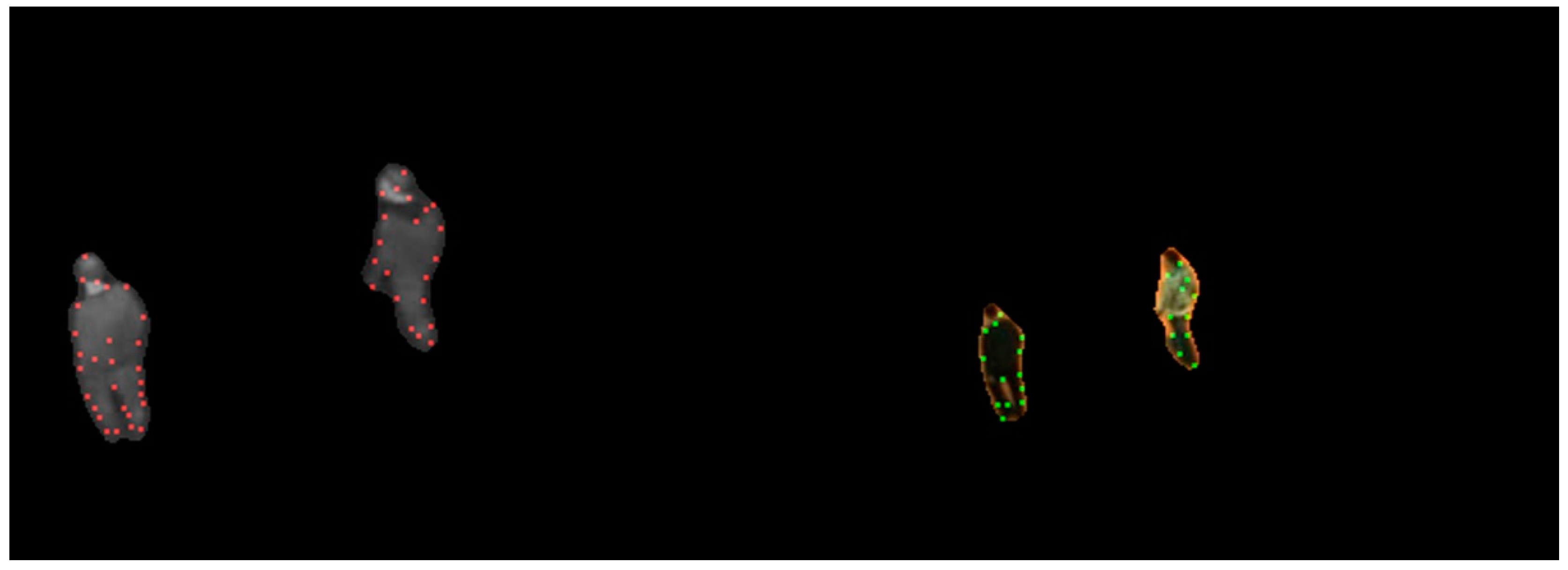
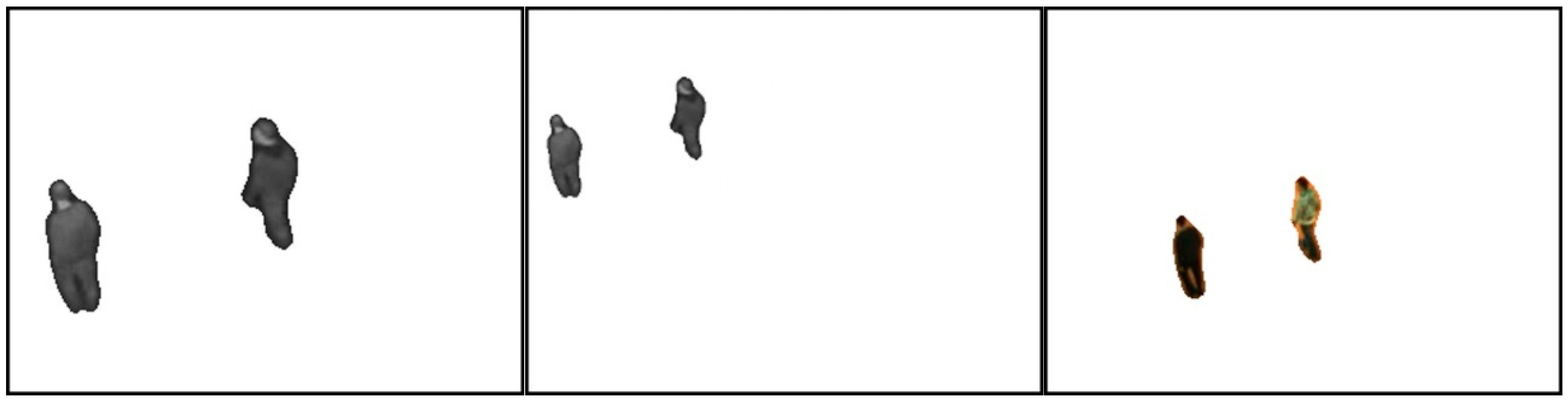
3.2. Initialization
3.3. Coarse Registration
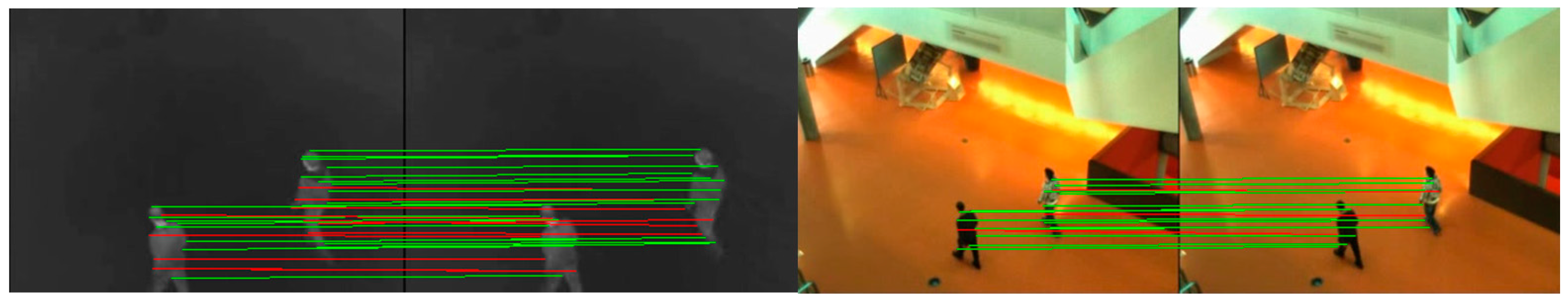
3.3.1. Homologous Keypoint Matching
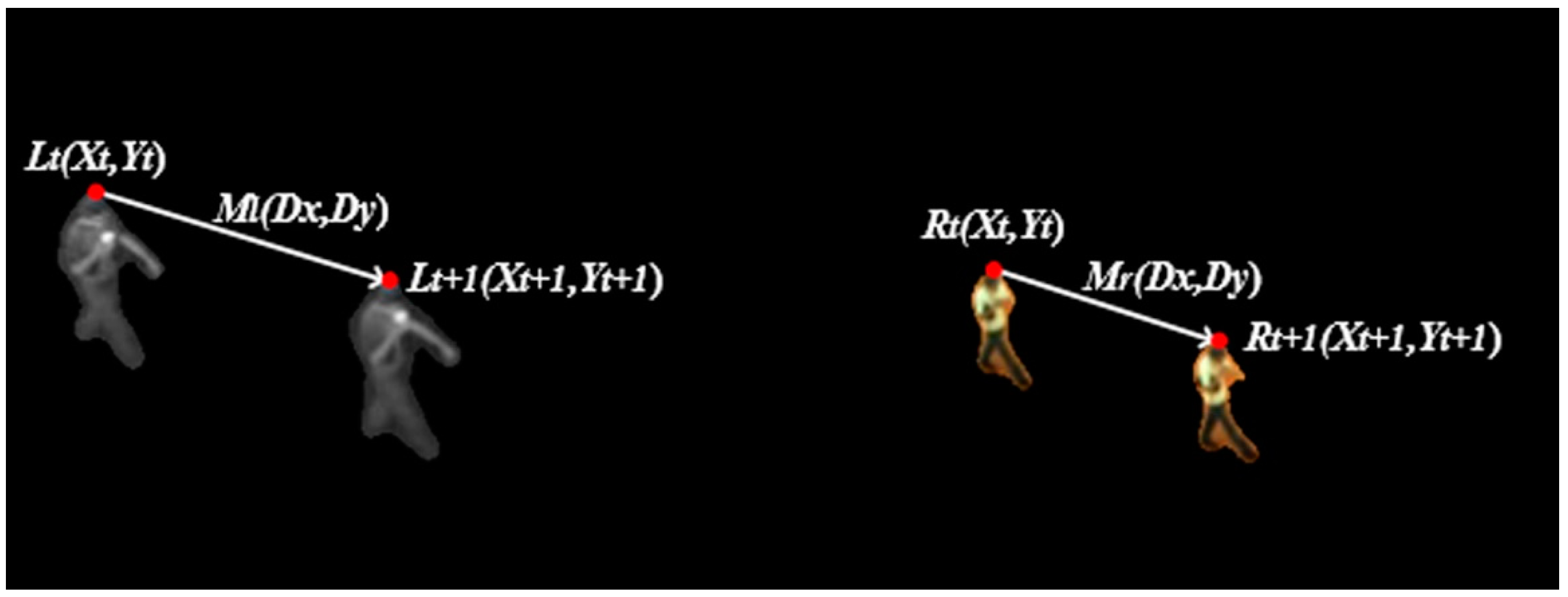
3.3.2. Calculating the Motion Vectors of Targets
| Algorithm 1. Interframe Motion Vector of Target Calculation |
| Repeat times ( is the number of homologous correspondences.) |
| 1. Pick a homologous correspondence in sequence. |
| 2. Calculate the motion vector of the correspondence . |
| 3. Estimate the number of inliers in the vector. |
| Repeat times |
| • Pick a homologous correspondence in sequence. |
| • Calculate the transformed Euclidean distance error . |
| • If , the correspondence is considered as an inlier. |
| Select the motion vector with the most inliers as the interframe motion vector of target . |
3.3.3. Scale and Rotation Estimation
3.4. Precise Registration
3.4.1. Re-Location and Keypoint Description
- : Its normalized location (NL). It is calculated by:where is the centroid of the foreground, and is the position of the keypoint. When foreground detection and re-location are both perfect, the NL descriptors of a correct correspondence are identical.
- : Its histogram of edge orientation (HOE, [8,31,32]). Its construction is similar to that of the HOG (in Section 3.3.1). However, HOE only considers the orientations of the Canny edges of the targets, whereas HOG uses the gradient orientation of each pixel. It abandons the information in low-relevance regions, and uses the similarity between infrared and visible edges. The HOE descriptor is represented by:where is an index of the histogram, and is the proportion of points with index .
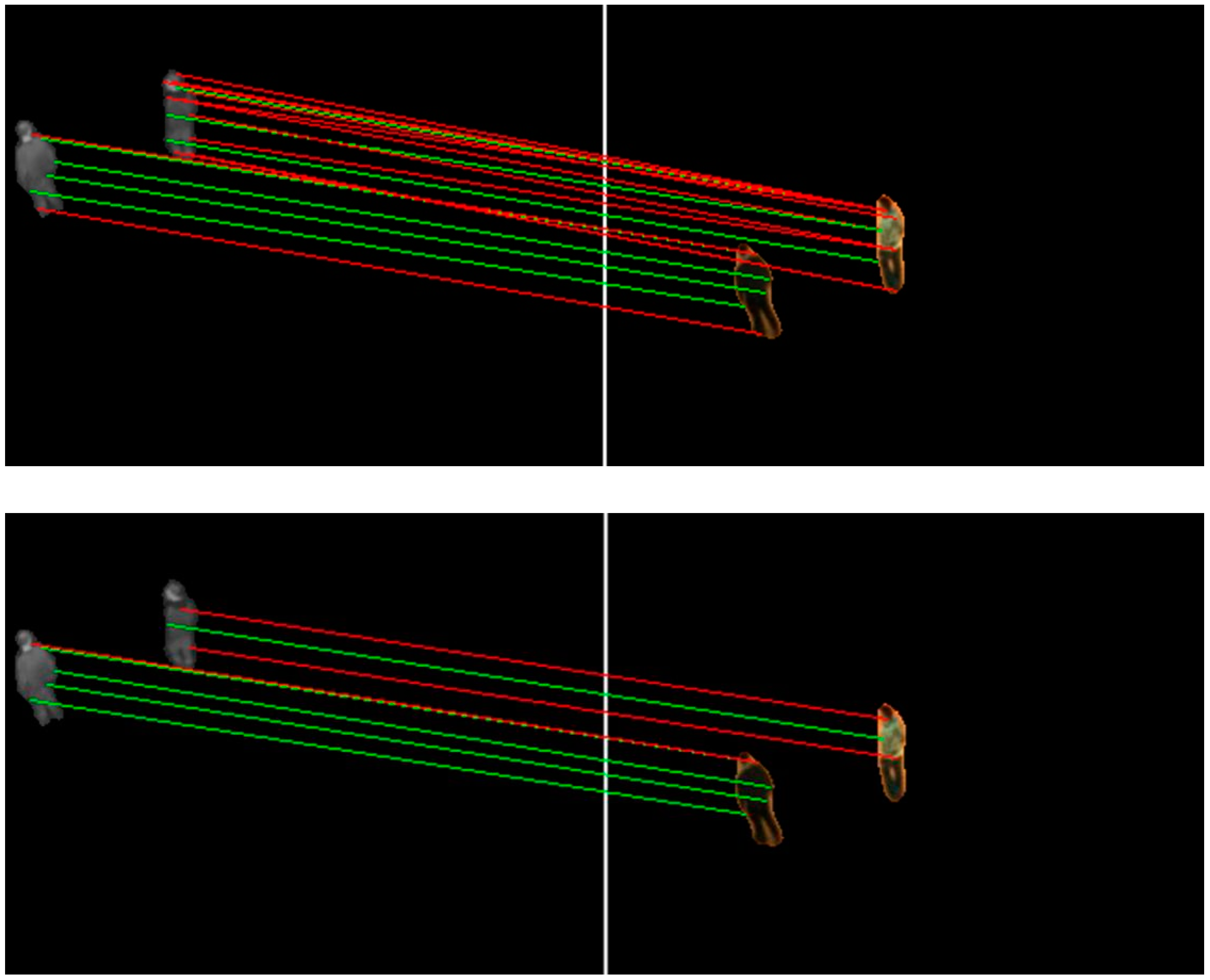
3.4.2. Matching
- : The normalized Euclidean distance between two keypoints:where and are the normalized locations of an infrared and a visible keypoint, respectively.
- : The difference between the HOE descriptors of two keypoints:where and are the ith component of an infrared and a visible HOE descriptor, respectively.
3.4.3. Mismatch Elimination
| Algorithm 2. Mismatch Elimination Based on Matching Direction |
| 1. Calculate the matching direction of each match. |
| 2. Encode every match using its matching direction. |
| 3. For every code, count the number of matches with this code to create the histogram of matching direction. |
| 4. Find the maximum value of histogram and the secondary maximum value . |
| 5. If , save the matches with code of the maximum; otherwise, abandon all. |
3.4.4. Finding the Best Global Homography
4. Experiment and Analysis
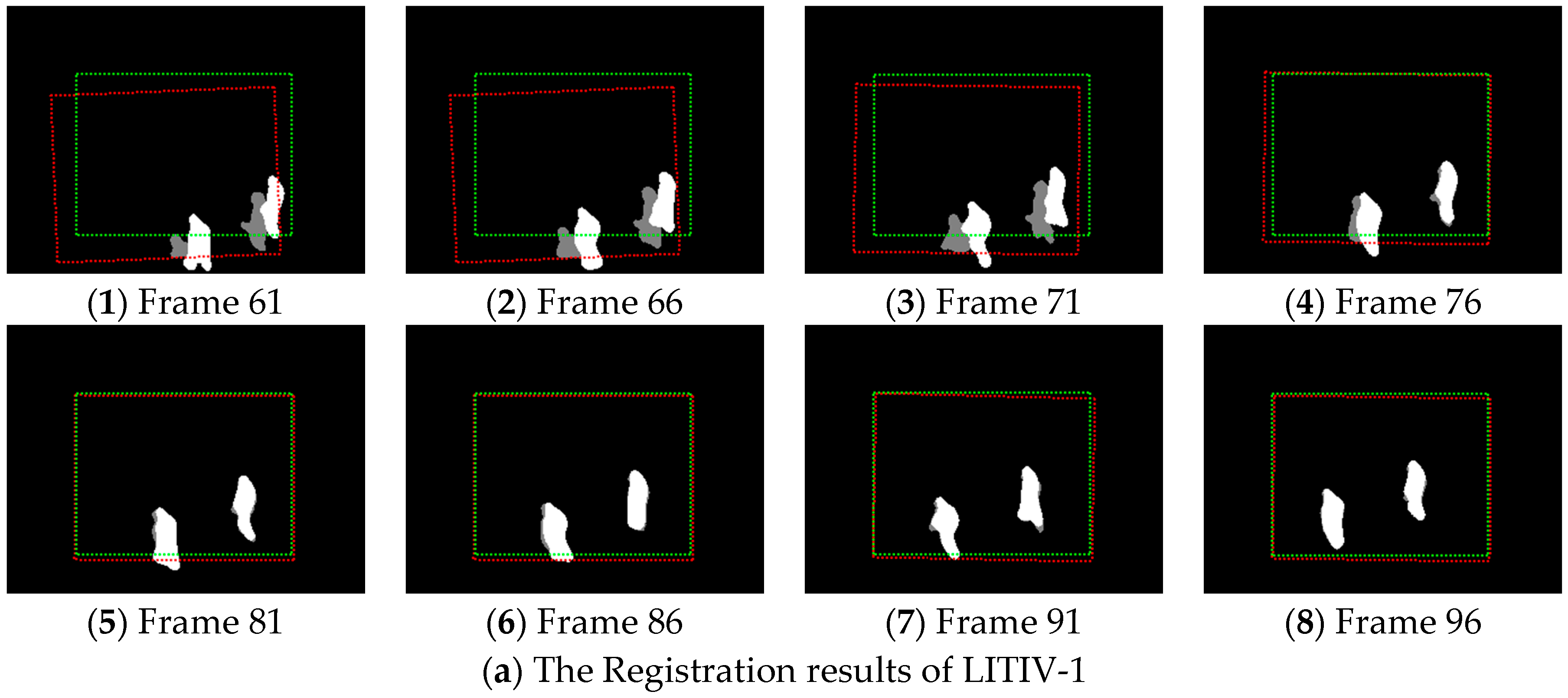
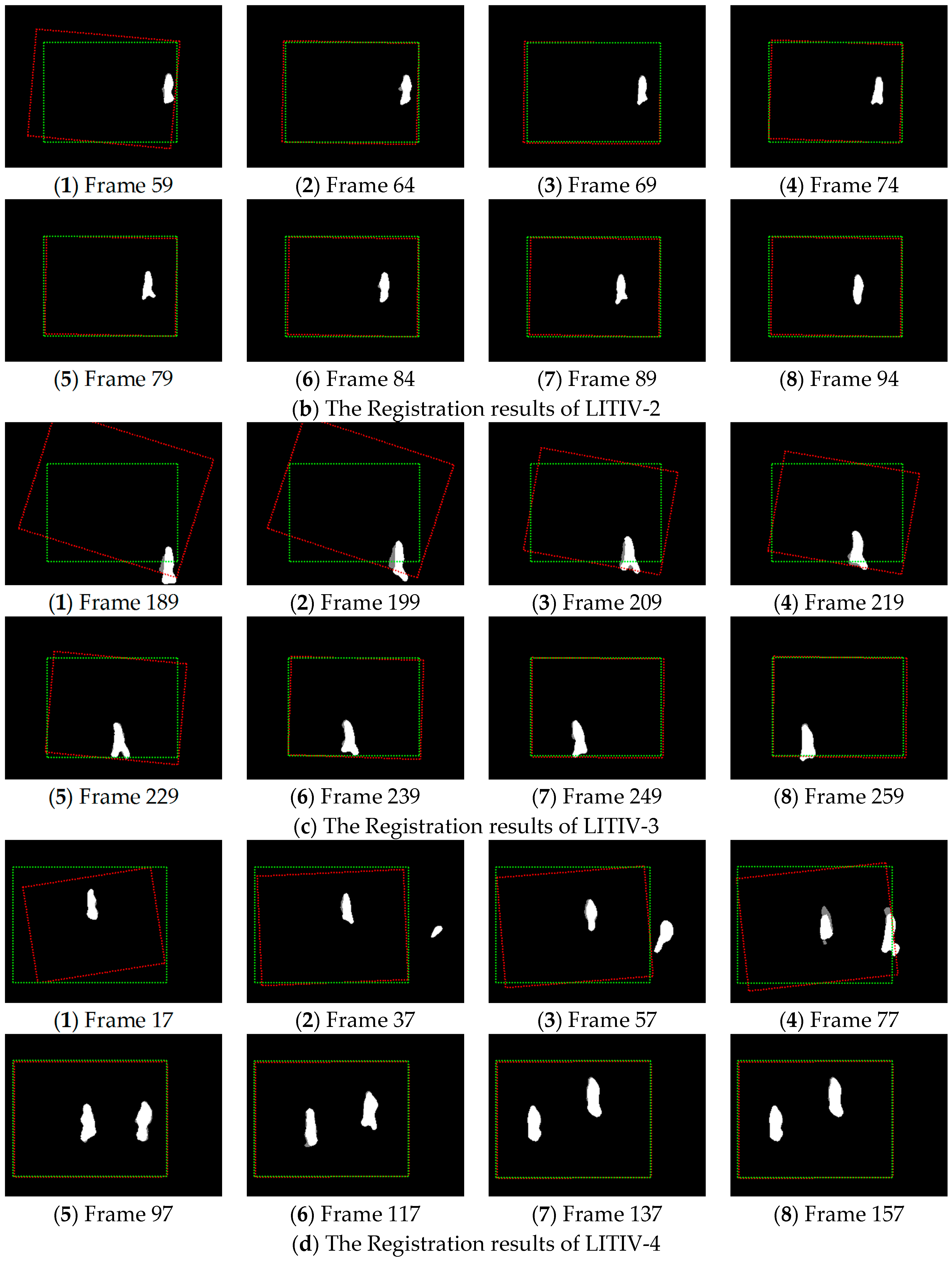
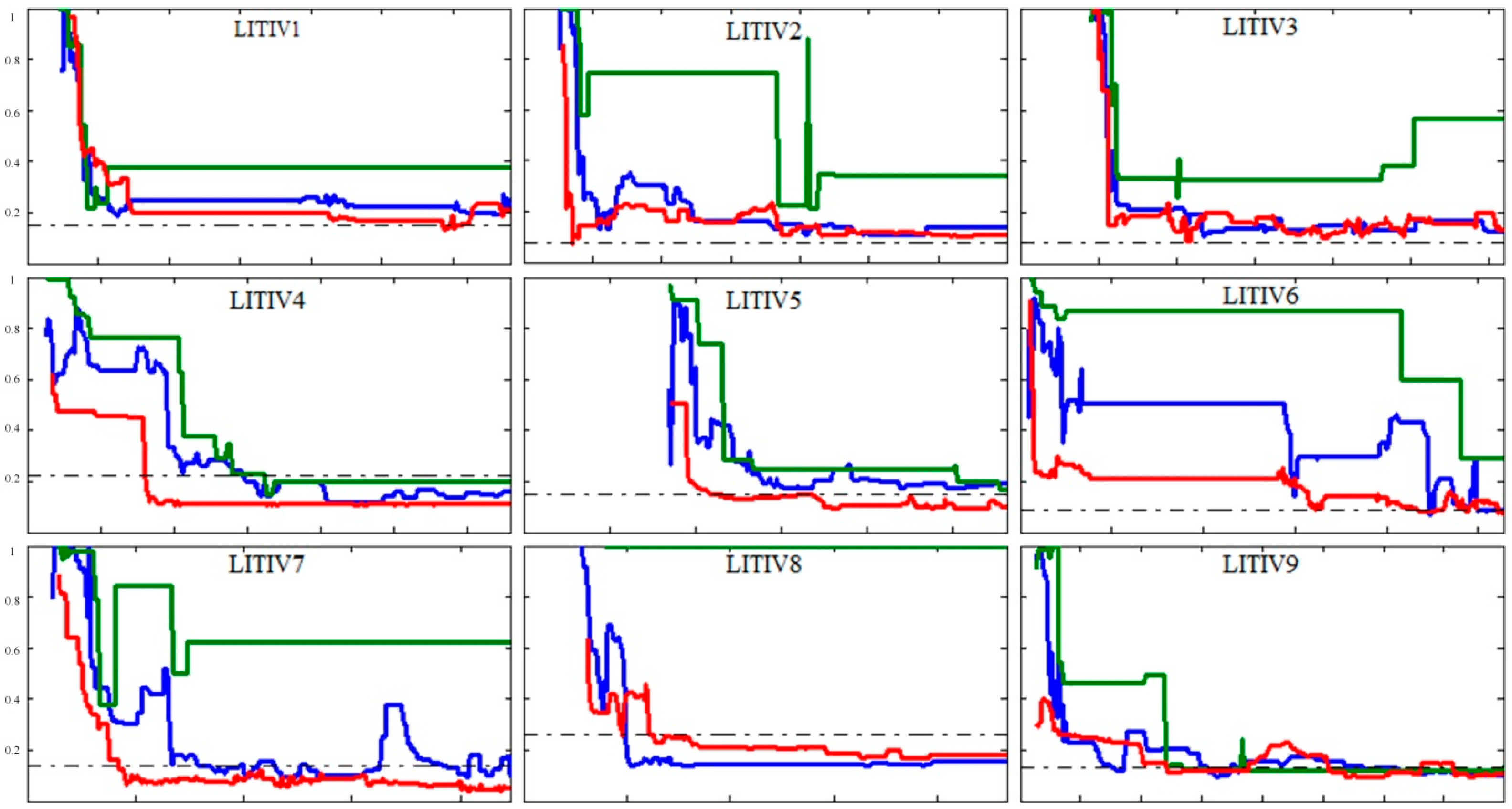
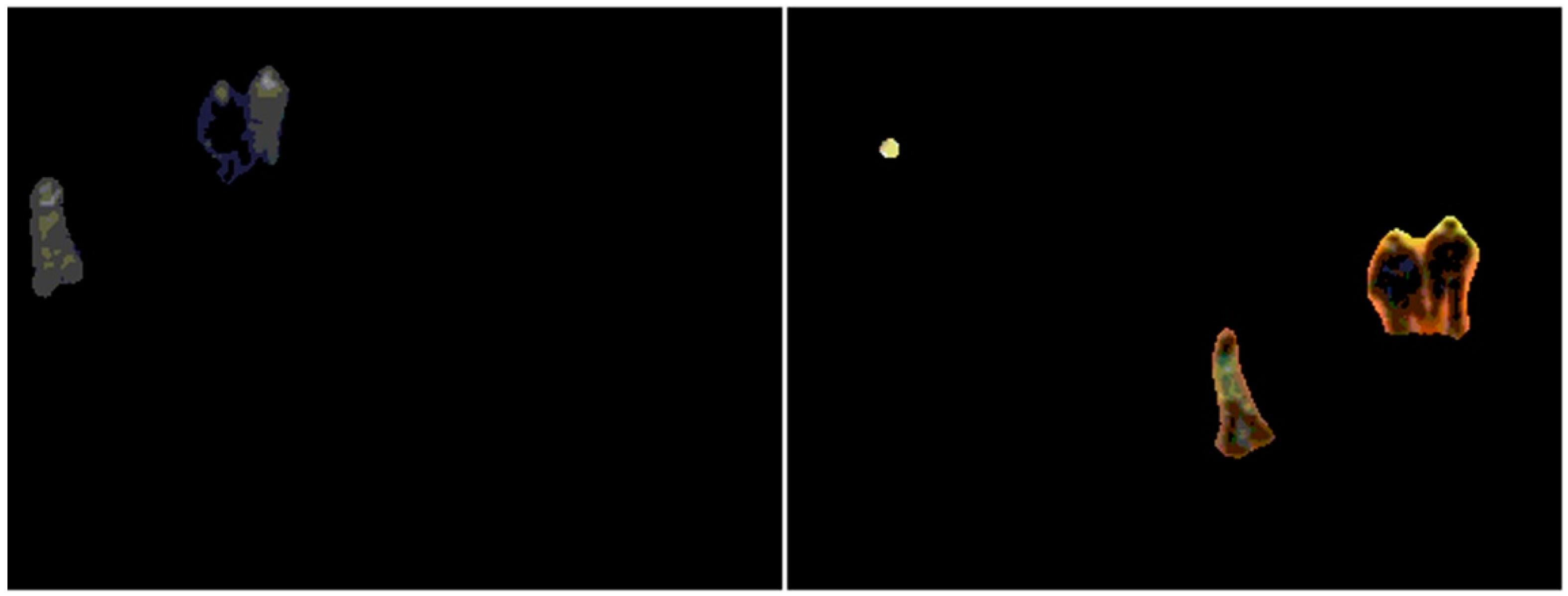
4.1. Experiment
4.2. Analysis
5. Conclusions
Acknowledgments
Author Contributions
Conflicts of Interest
References
- Hermosilla, G.; Gallardo, F.; Farias, G.; Martin, C.S. Fusion of Visible and Thermal Descriptors Using Genetic Algorithms for Face Recognition Systems. Sensors 2015, 15, 17944–17962. [Google Scholar] [CrossRef] [PubMed]
- Tsagaris, V.; Anastassopoulos, V. Fusion of visible and infrared imagery for night color vision. Displays 2005, 26, 191–196. [Google Scholar] [CrossRef]
- Ma, J.; Chen, C.; Li, C.; Huang, J. Infrared and visible image fusion via gradient transfer and total variation minimization. Inf. Fusion 2016, 31, 100–109. [Google Scholar] [CrossRef]
- González, A.; Fang, Z.; Socarras, Y.; Serrat, J.; Vázquez, D.; Xu, J.; López, A.M. Pedestrian Detection at Day/Night Time with Visible and FIR Cameras: A Comparison. Sensors 2016, 16, 820. [Google Scholar] [CrossRef] [PubMed]
- Singh, R.; Vatsa, M.; Noore, A. Integrated multilevel image fusion and match score fusion of visible and infrared face images for robust face recognition. Pattern Recognit. 2008, 41, 880–893. [Google Scholar] [CrossRef]
- Krotosky, S.J.; Trivedi, M.M. Mutual information based registration of multimodal stereo videos for person tracking. Comput. Vis. Image Underst. 2007, 106, 270–287. [Google Scholar] [CrossRef]
- Mokhtarian, F.; Suomela, R. Robust image corner detection through curvature scale space. IEEE Trans. Pattern Anal. Mach. Intell. 1998, 20, 1376–1381. [Google Scholar] [CrossRef]
- Aguilera, C.; Barrera, F.; Lumbreras, F.; Sappa, A.D.; Toledo, R. Multispectral image feature points. Sensors 2012, 12, 12661–12672. [Google Scholar] [CrossRef]
- Kong, S.G.; Heo, J.; Boughorbel, F.; Zheng, Y.; Abidi, B.R.; Koschan, A.; Yi, M.; Abidi, M.A. Multiscale fusion of visible and thermal IR images for illumination-invariant face recognition. Int. J. Comput. Vis. 2007, 71, 215–233. [Google Scholar] [CrossRef]
- Coiras, E.; Santamarı, J.; Miravet, C. Segment-based registration technique for visual-infrared images. Opt. Eng. 2000, 39, 282–289. [Google Scholar] [CrossRef]
- Torabi, A.; Massé, G.; Bilodeau, G.-A. An iterative integrated framework for thermal–visible image registration, sensor fusion, and people tracking for video surveillance applications. Comput. Vis. Image Underst. 2012, 116, 210–221. [Google Scholar] [CrossRef]
- Zhang, Y.; Zhang, X.; Maybank, S.J.; Yu, R. An IR and visible image sequence automatic registration method based on optical flow. Mach. Vis. Appl. 2013, 24, 947–958. [Google Scholar] [CrossRef]
- St-Charles, P.-L.; Bilodeau, G.-A.; Bergevin, R. Online multimodal video registration based on shape matching. In Proceedings of the IEEE Conference on Computer Vision and Pattern Recognition Workshops, Boston, MA, USA, 7–12 June 2015.
- Sonn, S.; Bilodeau, G.-A.; Galinier, P. Fast and accurate registration of visible and infrared videos. In Proceedings of the IEEE Conference on Computer Vision and Pattern Recognition Workshops, Portland, OR, USA, 23–28 June 2013.
- Gehrig, S.K.; Rabe, C. Real-time semi-global matching on the CPU. In Proceedings of the IEEE Conference on Computer Vision and Pattern Recognition Workshops, San Francisco, CA, USA, 13–18 June 2010.
- Gallup, D.; Frahm, J.-M.; Pollefeys, M. Piecewise planar and non-planar stereo for urban scene reconstruction. In Proceedings of the IEEE Conference on Computer Vision and Pattern Recognition (CVPR), San Francisco, CA, USA, 13–18 June 2010.
- Roche, A.; Malandain, G.; Pennec, X.; Ayache, N. The correlation ratio as a new similarity measure for multimodal image registration. In Proceedings of the Springer International Conference on Medical Image Computing and Computer-Assisted Intervention, Cambridge, MA, USA, 11–13 October 1998.
- Kim, K.S.; Lee, J.H.; Ra, J.B. Robust multi-sensor image registration by enhancing statistical correlation. In Proceedings of the IEEE 7th International Conference on Information Fusion, Philadelphia, PA, USA, 25–28 July 2005.
- Viola, P.; Wells, W.M., III. Alignment by maximization of mutual information. Int. J. Comput. Vis. 1997, 24, 137–154. [Google Scholar] [CrossRef]
- Legg, P.A.; Rosin, P.L.; Marshall, D.; Morgan, J.E. Feature neighbourhood mutual information for multi-modal image registration: An application to eye fundus imaging. Pattern Recognit. 2015, 48, 1937–1946. [Google Scholar] [CrossRef]
- Bilodeau, G.-A.; Torabi, A.; St-Charles, P.-L.; Riahi, D. Thermal-visible registration of human silhouettes: A similarity measure performance evaluation. Infrared Phys. Technol. 2014, 64, 79–86. [Google Scholar] [CrossRef]
- Hrkać, T.; Kalafatić, Z.; Krapac, J. Infrared-visual image registration based on corners and hausdorff distance. In Proceedings of the Springer 15th Scandinavian Conference on Image Analysis, Aalborg, Denmark, 10–14 June 2007.
- Ma, J.; Zhao, J.; Tian, J.; Yuille, A.L.; Tu, Z. Robust point matching via vector field consensus. IEEE Trans. Image Process. 2014, 23, 1706–1721. [Google Scholar]
- Awrangjeb, M.; Lu, G. An improved curvature scale-space corner detector and a robust corner matching approach for transformed image identification. IEEE Trans. Image Proc. 2008, 17, 2425–2441. [Google Scholar] [CrossRef]
- Ma, J.; Zhao, J.; Ma, Y.; Tian, J. Non-rigid visible and infrared face registration via regularized Gaussian fields criterion. Pattern Recognit. 2014, 48, 772–784. [Google Scholar] [CrossRef]
- Bilodeau, G.-A.; St-Onge, P.-L.; Garnier, R. Silhouette-based features for visible-infrared registration. In Proceedings of the IEEE Conference on Computer Vision and Pattern Recognition Workshops, Providence, RI, USA, 20–25 June 2011.
- Caspi, Y.; Simakov, D.; Irani, M. Feature-based sequence-to-sequence matching. Int. J. Comput. Vis. 2006, 68, 53–64. [Google Scholar] [CrossRef]
- Torabi, A.; Massé, G.; Bilodeau, G.-A. Feedback scheme for thermal-visible video registration, sensor fusion, and people tracking. In Proceedings of the IEEE Conference on Computer Vision and Pattern Recognition Workshops, San Francisco, CA, USA, 13–18 June 2010.
- St-Charles, P.-L.; Bilodeau, G.-A.; Bergevin, R. A self-adjusting approach to change detection based on background word consensus. In Proceedings of the IEEE Winter Conference on Applications of Computer Vision, Waikoloa, HI, USA, 6–9 January 2015.
- Fischler, M.A.; Bolles, R.C. Random sample consensus: A paradigm for model fitting with applications to image analysis and automated cartography. Commun. ACM 1981, 24, 381–395. [Google Scholar] [CrossRef]
- Kim, Y.S.; Lee, J.H.; Ra, J.B. Multi-sensor image registration based on intensity and edge orientation information. Pattern Recognit. 2008, 41, 3356–3365. [Google Scholar] [CrossRef]
- Dalal, N.; Triggs, B. Histograms of oriented gradients for human detection. In Proceedings of the IEEE Conference on Computer Vision and Pattern Recognition (CVPR), San Diego, CA, USA, 20–26 June 2005.


| Sequence Pair | Proposed | Charles et al. [13] | Sonn et al. [14] | Ground-Truth |
|---|---|---|---|---|
| LITIV-1 | 0.135 | 0.187 | 0.217 | 0.149 |
| LITIV-2 | 0.083 | 0.106 | 0.214 | 0.078 |
| LITIV-3 | 0.101 | 0.108 | 0.258 | 0.080 |
| LITIV-4 | 0.109 | 0.118 | 0.152 | 0.221 |
| LITIV-5 | 0.102 | 0.172 | 0.167 | 0.150 |
| LITIV-6 | 0.083 | 0.069 | 0.289 | 0.088 |
| LITIV-7 | 0.052 | 0.091 | 0.379 | 0.136 |
| LITIV-8 | 0.176 | 0.137 | 1.000 | 0.260 |
| LITIV-9 | 0.093 | 0.095 | 0.117 | 0.134 |
| Sequence Pair | Proposed | Charles et al. [13] | Sonn et al. [14] | Ground-Truth |
|---|---|---|---|---|
| LITIV-1 | 0.226 | 0.266 | 0.399 | 0.149 |
| LITIV-2 | 0.162 | 0.205 | 0.538 | 0.078 |
| LITIV-3 | 0.187 | 0.193 | 0.423 | 0.080 |
| LITIV-4 | 0.198 | 0.312 | 0.399 | 0.221 |
| LITIV-5 | 0.151 | 0.267 | 0.339 | 0.150 |
| LITIV-6 | 0.190 | 0.413 | 0.785 | 0.088 |
| LITIV-7 | 0.136 | 0.257 | 0.668 | 0.136 |
| LITIV-8 | 0.237 | 0.204 | 1.000 | 0.260 |
| LITIV-9 | 0.173 | 0.185 | 0.241 | 0.134 |
| Sequence Pair. | LITIV-1 | LITIV-2 | LITIV-3 | LITIV-4 | LITIV-5 | LITIV-6 | LITIV-7 | LITIV-8 | LITIV-9 |
|---|---|---|---|---|---|---|---|---|---|
| Computing times (s) | 0.056 | 0.142 | 0.085 | 0.163 | 0.110 | 0.116 | 0.108 | 0.103 | 0.101 |
© 2017 by the authors. Licensee MDPI, Basel, Switzerland. This article is an open access article distributed under the terms and conditions of the Creative Commons Attribution (CC BY) license ( http://creativecommons.org/licenses/by/4.0/).
Share and Cite
Sun, X.; Xu, T.; Zhang, J.; Li, X. A Hierarchical Framework Combining Motion and Feature Information for Infrared-Visible Video Registration. Sensors 2017, 17, 384. https://doi.org/10.3390/s17020384
Sun X, Xu T, Zhang J, Li X. A Hierarchical Framework Combining Motion and Feature Information for Infrared-Visible Video Registration. Sensors. 2017; 17(2):384. https://doi.org/10.3390/s17020384
Chicago/Turabian StyleSun, Xinglong, Tingfa Xu, Jizhou Zhang, and Xiangmin Li. 2017. "A Hierarchical Framework Combining Motion and Feature Information for Infrared-Visible Video Registration" Sensors 17, no. 2: 384. https://doi.org/10.3390/s17020384