
Advanced Spatial-Division Multiplexed Measurement Systems Propositions—From Telecommunication to Sensing Applications: A Review


Abstract
:1. Introduction
1.1. Background Introduction
1.2. Spatial Division of Information Models for Fiber-Optic Sensing Components
1.3. Benefits of SDM Sensing Systems
1.3.1. Measuring More Parameters
1.3.2. Multi-Parameter Discriminative Capability
1.3.3. Accuracy Improvement
1.3.4. Detection Speed Enhancement
2. Key Components of SDM Technique
2.1. Laser Beam Shaping
2.2. Mode Generation and Conversion
2.3. Multiplexers and De-Multiplexers
2.4. Multicore Elements Using Special Fibers
2.5. Multicore Head of Sensor Elements Using LPG and Other Specific Fibers
2.6. Single-Core Multimode Elements as Asymmetrical Coupler
2.7. SDM Amplifiers and EDFAs
2.8. Opto-Electronic Sources and Detection Units of Sensing Systems
3. Examples of SDM Based Sensing Systems
3.1. Distributed Sensors Based on Mode-Division Multiplexing (MDM)
3.1.1. Operation Principle
3.1.2. Fabrication Methods
3.1.3. Experimental Design
3.1.4. Sensing Applications
3.2. Distributed Sensors Based on Core Multiplexing
3.2.1. Operation Principle
3.2.2. Fabrication Methods
3.2.3. Experimental Design
3.2.4. Sensing Applications
3.3. Fiber Bragg Grating (FBG) Sensors Based on Core Multiplexing
3.3.1. Operation Principle
3.3.2. Fabrication Methods
3.3.3. Experimental Design
3.3.4. Sensing Applications
3.4. Other Examples of SDM Sensors
3.4.1. Whispering Gallery Modes for Chemical Species Measurements
3.4.2. Screw/Twisted Modes for Examining Water Quality
3.4.3. Optical Beam Shaping for Improving Cantilever Deflection Measurements
4. Prospective Outlook
4.1. Summary and Comparison
4.1.1. SDM Sensing Systems for Various Markets and Applications
4.1.2. Multiplexing Merits in Sensing System Designs
4.2. Challenges for SDM Measurement Systems
4.2.1. Component Cost for SDM Sensing Systems
4.2.2. The Effects of Noise and Nonlinearity on SDM Sensing Systems
5. Concluding Remarks
Acknowledgments
Conflicts of Interest
References
- Winzer, P.J. Making spatial multiplexing a reality. Nat. Photonics 2014, 8, 345–348. [Google Scholar] [CrossRef]
- Essiambre, R.-J.; Kramer, G.; Winzer, P.J.; Foschini, G.J.; Goebel, B. Capacity limits of optical fiber networks. J. Lightwave Technol. 2010, 28, 662–701. [Google Scholar] [CrossRef]
- Richardson, D.J.; Fini, J.M.; Nelson, L.E. Space-division multiplexing in optical fibres. Nat. Photonics 2013, 7, 354–362. [Google Scholar] [CrossRef]
- Yaman, F.; Bai, N.; Zhu, B.; Wang, T.; Li, G. Long distance transmission in few-mode fibers. Opt. Express 2010, 18, 13250–13257. [Google Scholar] [CrossRef] [PubMed]
- Van Uden, R.G.H.; Correa, R.A.; Lopez, E.A.; Huijskens, F.M.; Xia, C.; Li, G.; Schülzgen, A.; Waardt, H.D.; Koonen, A.M.J.; Okonkwo, C.M. Ultra-high-density spatial division multiplexing with a few-mode multicore fibre. Nat. Photonics 2014, 8, 865–870. [Google Scholar] [CrossRef]
- Pan, Z.; He, X.; Weng, Y. Hardware efficient frequency domain equalization in few-mode fiber coherent transmission systems. In Proceedings of the SPIE; Next-Generation Optical Communication: Components, Sub-Systems, and Systems III, San Francisco, CA, USA, 1 February 2014.
- Grattan, K.T.V.; Sun, T. Fiber optic sensor technology: An overview. Sens. Actuators A Phys. 2000, 82, 40–61. [Google Scholar] [CrossRef]
- Murshid, S.; Grossman, B.; Narakorn, P. Spatial domain multiplexing: A new dimension in fiber optic multiplexing. Opt. Laser Technol. 2008, 40, 1030–1036. [Google Scholar] [CrossRef]
- Boleininger, A.; Lake, T.; Hami, S.; Vallance, C. Whispering gallery modes in standard optical fibres for fibre profiling measurements and sensing of unlabelled chemical species. Sensors 2010, 10, 1765–1781. [Google Scholar] [CrossRef] [PubMed]
- Beaulieua, L.Y.; Godin, M.; Larochec, O.; Tabard-Cossac, V.; Grutter, P.A. Complete analysis of the laser beam deflection systems used in cantilever-based systems. Ultramicroscopy 2007, 107, 422–430. [Google Scholar] [CrossRef] [PubMed]
- Borecki, M.; Korwin-Pawlowski, M.L.; Beblowska, M.; Szmidt, J.; Szmidt, M.; Duk, M.; Urbańska, K.; Jakubowski, A. Intelligent photonic sensors for application, in decentralized wastewater systems. In Waste Water—Evaluation and Management; Einschlag, F.S.G., Ed.; InTech: Rijeka, Croatia, 2011; pp. 181–202. [Google Scholar]
- Weng, Y.; He, X.; Wang, J.; Pan, Z. All-optical ultrafast wavelength and mode converter based on inter-modal nonlinear wave mixing in few-mode fibers. In Proceedings of the Conference on Lasers and Electro-Optics (CLEO), San Jose, CA, USA, 10–15 May 2015.
- Carboni, C.; Li, G. Novel applications of space-division multiplexing. Front. Optoelectron. 2016, 9, 270–276. [Google Scholar] [CrossRef]
- Li, A.; Wang, Y.; Fang, J.; Li, M.-J.; Kim, B.Y.; Shieh, W. Few-mode fiber multi-parameter sensor with distributed temperature and strain discrimination. Opt. Lett. 2015, 40, 1488–1491. [Google Scholar] [CrossRef] [PubMed]
- Tang, M.; Zhao, Z.; Gan, L.; Wu, H.; Wang, R.; Li, B.; Fu, S.; Liu, H.; Liu, D.; Wei, H.; et al. Spatial-division multiplexed optical sensing using MCF and FMF. In Proceedings of the Advanced Photonics Congress 2016, Vancouver, BC, Canada, 18–20 July 2016.
- Gloge, D. Weakly guiding fibers. Appl. Opt. 1971, 10, 2252–2258. [Google Scholar] [CrossRef] [PubMed]
- Richardson, D.J. Filling the light pipe. Science 2010, 330, 327–328. [Google Scholar] [CrossRef] [PubMed]
- Grattan, L.S.; Meggitt, B.T. Optical Fiber Sensor Technology: Devices and Technology, 1st ed.; Springer US: New York, NY, USA, 1998; pp. 117–166. [Google Scholar]
- Antonelli, C.; Mecozzi, A.; Shtaif, M.; Winzer, P.J. Stokes-space analysis of modal dispersion in fibers with multiple mode transmission. Opt. Express 2012, 20, 11718–11733. [Google Scholar] [CrossRef] [PubMed]
- Agrawal, G.P. Fiber-Optic Communication Systems, 4th ed.; Wiley: New York, NY, USA, 2010; pp. 460–499. [Google Scholar]
- Pan, Z.; Weng, Y.; He, X.; Wang, J. Adaptive frequency-domain equalization and MIMO signal processing in mode division multiplexing systems using few-mode fibers. In Proceedings of the Signal Processing in Photonic Communications (SPPCom), Vancouver, BC, Canada, 18–20 July 2016.
- Rao, Y.J.; Ran, Z.L.; Zhou, C.X. Fiber-optic Fabry-Perot sensors based on a combination of spatial-frequency division multiplexing and wavelength division multiplexing formed by chirped fiber Bragg grating pairs. Appl. Opt. 2006, 45, 5815–5818. [Google Scholar] [CrossRef] [PubMed]
- Berdagué, S.; Facq, P. Mode division multiplexing in optical fibers. Appl. Opt. 1982, 21, 1950–1955. [Google Scholar] [CrossRef] [PubMed]
- Weng, Y.; Ip, E.; Pan, Z.; Wang, T. Few-mode distributed optical fiber sensors. In Proceedings of the Advanced Photonics Congress 2015, Boston, MA, USA, 27 June–1 July 2015.
- Carpenter, J.; Thomsen, B.C.; Wilkinson, T.D. Degenerate mode-group division multiplexing. J. Lightwave Technol. 2012, 30, 3946–3952. [Google Scholar] [CrossRef]
- Chen, D.; Wu, C.; Tse, M.L.V.; Tam, H.-Y. Hydrostatic pressure sensor based on mode interference of a few mode fiber. Prog. Electromagn. Res. 2011, 119, 335–343. [Google Scholar] [CrossRef]
- Sun, A.; Wu, Z. Multimode interference in single mode–multimode FBG for simultaneous measurement of strain and bending. IEEE Sens. J. 2015, 15, 3390–3394. [Google Scholar] [CrossRef]
- Li, A.; Wang, Y.; Hu, Q.; Che, D.; Chen, X.; Shieh, W. Measurement of distributed mode coupling in a few-mode fiber using a reconfigurable Brillouin OTDR. Opt. Lett. 2014, 39, 6418–6421. [Google Scholar] [CrossRef] [PubMed]
- Pan, Z.; Weng, Y.; Wang, J. Investigation of nonlinear effects in few-mode fibers. Photonic Netw. Commun. 2016, 31, 305–315. [Google Scholar] [CrossRef]
- Bao, X.; Chen, L. Recent progress in distributed fiber optic sensors. Sensors 2012, 12, 8601–8639. [Google Scholar] [CrossRef] [PubMed]
- Spillman, W.B. Multimode fiber-optic pressure sensor based on the photoelastic effect. Opt. Lett. 1982, 7, 388–390. [Google Scholar] [CrossRef] [PubMed]
- Parker, T.R.; Farhadiroushan, M.; Handerek, V.A.; Rogers, A.J. Temperature and strain dependence of the power level and frequency of spontaneous Brillouin scattering in optical fibers. Opt. Lett. 1997, 22, 787–789. [Google Scholar] [CrossRef] [PubMed]
- Alahbabi, M.N.; Cho, Y.T.; Newson, T.P. Simultaneous temperature and strain measurement with combined spontaneous Raman and Brillouin scattering. Opt. Lett. 2005, 30, 1276–1278. [Google Scholar] [CrossRef] [PubMed]
- Liu, X.; Bao, X. Brillouin spectrum in LEAF and simultaneous temperature and strain measurement. J. Lightwave Technol. 2012, 30, 1053–1059. [Google Scholar] [CrossRef]
- Wang, L.; LaRochelle, S. Design of eight-mode polarization-maintaining few-mode fiber for multiple-input multiple-output-free spatial division multiplexing. Opt. Lett. 2015, 40, 5846–5849. [Google Scholar] [CrossRef] [PubMed]
- Souza, K.D. Significance of coherent Rayleigh noise in fibre-optic distributed temperature sensing based on spontaneous Brillouin scattering. Meas. Sci. Technol. 2006, 17, 1065–1069. [Google Scholar] [CrossRef]
- Wood, T.H.; Linke, R.A.; Kasper, B.L.; Carr, E.C. Observation of coherent Rayleigh noise in single-source bidirectional optical fiber systems. J. Lightwave Technol. 1988, 6, 346–352. [Google Scholar] [CrossRef]
- Song, K.Y.; Kim, Y.H. Characterization of stimulated Brillouin scattering in a few-mode fiber. Opt. Lett. 2013, 38, 4841–4844. [Google Scholar] [CrossRef] [PubMed]
- Tanimola, F.; Hill, D. Distributed fibre optic sensors for pipeline protection. J. Nat. Gas Sci. Eng. 2009, 1, 134–143. [Google Scholar] [CrossRef]
- Lopez-Higuera, J.M.; Rodriguez Cobo, L.; Incera, A.Q.; Cobo, A. Fiber optic sensors in structural health monitoring. J. Lightwave Technol. 2011, 29, 587–608. [Google Scholar] [CrossRef]
- Bolognini, G.; Hartog, A. Raman-based fibre sensors: Trends and applications. Opt. Fiber Technol. 2013, 19, 678–688. [Google Scholar] [CrossRef]
- Golub, M.A.; Shwartz, S.; Ruschin, S. Space-division multiplexing of coherent beams by diffractive optical elements. In Proceedings of the Optical Fiber Communication (OFC), Anaheim, CA, USA, 17–21 March 2013.
- Demas, J.; Rishøj, L.; Ramachandran, S. Free-space beam shaping for precise control and conversion of modes in optical fiber. Opt. Express 2015, 23, 28531–28545. [Google Scholar] [CrossRef] [PubMed]
- Shwartz, S.; Golub, M.; Ruschin, S. Diffractive optical elements for mode-division multiplexing of temporal signals with the aid of Laguerre–Gaussian modes. Appl. Opt. 2013, 52, 2659–2669. [Google Scholar] [CrossRef] [PubMed]
- Mayeh, M.; Farahi, F. Laser beam shaping and mode conversion in optical fibers. Photonic Sens. 2011, 1, 187–198. [Google Scholar] [CrossRef]
- Weng, Y.; He, X.; Wang, J.; Pan, Z. All-optical ultrafast wavelength and mode converter based on inter-modal four-wave mixing in few-mode fibers. Opt. Commun. 2015, 348, 7–12. [Google Scholar] [CrossRef]
- Chen, H.; Uden, R.V.; Okonkwo, C.; Koonen, T. Compact spatial multiplexers for mode division multiplexing. Opt. Express 2014, 22, 31582–31594. [Google Scholar] [CrossRef] [PubMed]
- Fan, S.; Kahn, J.M. Principal modes in multimode waveguides. Opt. Lett. 2005, 30, 135–137. [Google Scholar] [CrossRef] [PubMed]
- Ziolowicz, A.; Bienkowska, B.; Budnicki, D.; Jozwik, M.; Ostrowski, L.; Murawski, M.; Pytel, A.; Tenderenda, T.; Wojcik, G.; Szostkiewicz, L.; et al. Supermode interference in dual-core hole-assisted fiber for sensing. In Proceedings of the SPIE Optical Fibers and Their Applications 2015, Naleczow, Poland, 22 September 2015.
- Carpenter, J.; Eggleton, B.J.; Schröder, J. Observation of Eisenbud–Wigner–Smith states as principal modes in multimode fibre. Nat. Photonics 2015, 9, 751–757. [Google Scholar] [CrossRef]
- Milione, G.; Nolan, D.A.; Alfano, R.R. Determining principal modes in a multimode optical fiber using the mode dependent signal delay method. J. Opt. Soc. Am. B 2015, 32, 143–149. [Google Scholar] [CrossRef]
- Tucker, J.R.; Rakić, A.D.; O’Brien, C.J.; Zvyagin, A.V. Effect of multiple transverse modes in self-mixing sensors based on vertical-cavity surface-emitting lasers. Appl. Opt. 2007, 46, 611–619. [Google Scholar] [CrossRef] [PubMed]
- Chen, C.; Yang, H.; Tong, S.; Lou, Y. Changes in orbital-angular-momentum modes of a propagated vortex Gaussian beam through weak-to-strong atmospheric turbulence. Opt. Express 2016, 24, 6959–6975. [Google Scholar] [CrossRef] [PubMed]
- Cvijetic, N.; Milione, G.; Ip, E.; Wang, T. Detecting lateral motion using light’s orbital angular momentum. Sci. Rep. 2015, 5, 15422. [Google Scholar] [CrossRef] [PubMed]
- Weng, Y.; Pan, Z. Orbital-angular-momentum-based image sensor using high resolution photoacoustic tomography. In Proceedings of the Advanced Photonics, Boston, MA, USA, 27 June–1 July 2015.
- Matsko, A.B.; Ilchenko, V.S. Optical resonators with whispering gallery modes I: Basics. IEEE JSTQE 2006, 12, 3–14. [Google Scholar] [CrossRef]
- Foreman, M.R.; Swaim, J.D.; Vollmer, F. Whispering gallery mode sensors. Adv. Opt. Photonics 2015, 7, 168–240. [Google Scholar] [CrossRef] [PubMed]
- Sotsky, A.B.; Sotskaya, L.I. Modes of capillary optical fibers. Opt. Commun. 2004, 230, 67–79. [Google Scholar] [CrossRef]
- Dutt, A.; Mahapatra, S.; Varshney, S.K. Capillary optical fibers: Design and applications for attaining a large effective mode area. J. Opt. Soc. Am. B 2011, 28, 1431–1438. [Google Scholar] [CrossRef]
- Flamm, D.; Naidoo, D.; Schulze, C.; Forbes, A.; Duparré, M. Mode analysis with a spatial light modulator as a correlation filter. Opt. Lett. 2012, 37, 2478–2480. [Google Scholar] [CrossRef] [PubMed]
- Labroille, G.; Denolle, B.; Jian, P.; Genevaux, P.; Treps, N.; Morizur, J.-F. Efficient and mode selective spatial mode multiplexer based on multi-plane light conversion. Opt. Express 2014, 22, 15599–15607. [Google Scholar] [CrossRef] [PubMed]
- Hoyningen-Huene, J.V.; Ryf, R.; Winzer, P. LCoS-based mode shaper for few-mode fiber. Opt. Express 2013, 21, 18097–18110. [Google Scholar] [CrossRef] [PubMed]
- Salsi, M.; Koebele, C.; Sperti, D.; Tran, P.; Mardoyan, H.; Brindel, P.; Bigo, S.; Boutin, A.; Verluise, F.; Sillard, P.; et al. Mode-division multiplexing of 2 × 100 Gb/s channels using an LCOS-based spatial modulator. J. Lightwave Technol. 2012, 30, 618–623. [Google Scholar] [CrossRef]
- Li, A.; Chen, X.; Amin, A.A.; Shieh, W. Fused fiber mode couplers for few-mode transmission. IEEE Photonics Technol. Lett. 2012, 24, 1953–1956. [Google Scholar]
- Weng, Y.; He, X.; Wang, J.; Zhu, B.; Pan, Z. Mode and Wavelength Conversion Based on Inter-Modal Four-Wave Mixing in a Highly Nonlinear Few-Mode Fiber. In Proceedings of the Signal Processing in Photonic Communications (SPPCOM), San Diego, CA, USA, 13–17 July 2014.
- Li, G. Recent advances in coherent optical communication. Adv. Opt. Photonics 2009, 1, 279–307. [Google Scholar] [CrossRef]
- Peral, E.; Yariv, A. Supermodes of grating-coupled multimode waveguides and application to mode conversion between copropagating modes mediated by backward Bragg scattering. J. Lightwave Technol. 2002, 17, 942–947. [Google Scholar] [CrossRef]
- Giles, I.; Obeysekara, A.; Chen, R.; Giles, D.; Poletti, F.; Richardson, D. Fiber LPG mode converters and mode selection technique for multimode SDM. IEEE Photonics Technol. Lett. 2012, 24, 1922–1925. [Google Scholar] [CrossRef]
- Xia, C.; Bai, N.; Ozdur, I.; Zhou, X.; Li, G. Supermodes for optical transmission. Opt. Express 2011, 19, 16653–16664. [Google Scholar] [CrossRef] [PubMed]
- Fang, L.; Wang, J. Mode Conversion and Orbital Angular Momentum Transfer among Multiple Modes by Helical Gratings. IEEE J. Quantum Electron. 2016, 52, 6600306. [Google Scholar] [CrossRef]
- Martinelli, M.; Huguenin, J.A.O.; Nussenzveig, P.; Khoury, A.Z. Orbital angular momentum exchange in an optical parametric oscillator. Phys. Rev. A 2004, 70, 013812. [Google Scholar] [CrossRef]
- Huang, L.; Wang, J.; Peng, W.; Zhang, W.; Bo, F.; Yu, X.; Gao, F.; Chang, P.; Song, X.; Zhang, G.; et al. Mode conversion in a tapered fiber via a whispering gallery mode resonator and its application as add/drop filter. Opt. Lett. 2016, 41, 638–641. [Google Scholar] [CrossRef] [PubMed]
- Farnesi, D.; Barucci, A.; Righini, G.C.; Berneschi, S.; Soria, S.; Nunzi Conti, G. Optical frequency conversion in silica-whispering-gallery-mode micro-spherical resonators. Phys. Rev. Lett. 2014, 112, 093901. [Google Scholar] [CrossRef] [PubMed]
- Saitoh, F.; Saitoh, K.; Koshiba, M. A design method of a fiber-based mode multi/demultiplexer for mode-division multiplexing. Opt. Express 2010, 18, 4709–4716. [Google Scholar] [CrossRef] [PubMed]
- Bouchal, Z.; Haderka, O.; Celechovsky, R. Selective excitation of vortex fiber modes using a spatial light modulator. New J. Phys. 2005, 7, 1–15. [Google Scholar] [CrossRef]
- Li, G.; Bai, N.; Zhao, N.; Xia, C. Space-division multiplexing: The next frontier in optical communication. Adv. Opt. Photonics 2014, 6, 413–487. [Google Scholar] [CrossRef]
- Li, A.; Hu, Q.; Che, D.; Wang, Y.; Shieh, W. Measurement of distributed mode coupling in a few-mode fiber using a Brillouin optical time domain reflectometer. In Proceedings of the European Conference on Optical Communication (ECOC), Cannes, France, 21–25 September 2014.
- Fontaine, N.K.; Ryf, R.; Bland-Hawthorn, J.; Leon-Saval, S.G. Geometric requirements for photonic lanterns in space division multiplexing. Opt. Express 2012, 20, 27123–27132. [Google Scholar] [CrossRef] [PubMed]
- Leon-Saval, S.G.; Fontaine, N.K.; Salazar-Gil, J.R.; Ercan, B.; Ryf, R.; Bland-Hawthorn, J. Mode-selective photonic lanterns for space-division multiplexing. Opt. Express 2014, 22, 1036–1044. [Google Scholar] [CrossRef] [PubMed]
- Napierala, M.; Murawski, M.; Szymanski, M.; Ostrowski, L.; Szostkiewicz, L.; Mergo, P.; Jaroszewicz, L.; Nasilowski, T. Optical fiber elements for addressing individual cores in multicore optical fiber sensors. In Proceedings of the 23rd International Conference on Optical Fibre Sensors, Santander, Spain, 2 June 2014.
- Korotky, S.K. Price-points for components of multi-core fiber communication systems in backbone optical networks. J. Opt. Commun. Netw. 2012, 4, 426–435. [Google Scholar] [CrossRef]
- Jain, S.; Rancaño, V.J.F.; May-Smith, T.C.; Petropoulos, P.; Sahu, J.K.; Richardson, D.J. Multi-element fiber technology for space-division multiplexing applications. Opt. Express 2014, 22, 3787–3796. [Google Scholar] [CrossRef] [PubMed]
- Uchiyama, T.; Hamada, N.; Cai, C. Highly sensitive CMOS magnetoimpedance sensor using miniature multi-core head based on amorphous wire. IEEE Trans. Magn. 2014, 50, 4005404. [Google Scholar] [CrossRef]
- Saffari, P.; Allsop, T.; Adebayo, A.; Webb, D.; Haynes, R.; Roth, M.M. Long period grating in multicore optical fiber: An ultra-sensitive vector bending sensor for low curvatures. Opt. Lett. 2014, 39, 3508–3511. [Google Scholar] [CrossRef] [PubMed]
- Chen, M.-Y.; Wei, J.; Sheng, Y.; Ren, N.-F. Design and optimization of fundamental mode filters based on long-period fiber gratings. Opt. Fiber Technol. 2016, 30, 89–94. [Google Scholar] [CrossRef]
- Wolinski, T.R.; Lesiak, P.; Domanski, A.W. Polarimetric optical fiber sensors of a new generation for industrial applications. Bull. Pol. Acad. Sci. Tech. Sci. 2008, 56, 125–132. [Google Scholar]
- Yuan, L.; Wang, X. Four-beam single fiber optic interferometer and its sensing characteristics. Sens. Actuators A Phys. 2007, 138, 9–15. [Google Scholar] [CrossRef]
- Borecki, M. Intelligent fiber optic sensor for estimating the concentration of a mixture-design and working principle. Sensors 2007, 7, 384–399. [Google Scholar] [CrossRef]
- Lane, S.; West, P.; François, A.; Meldrum, A. Protein biosensing with fluorescent microcapillaries. Opt. Express 2015, 23, 2577–2590. [Google Scholar] [CrossRef] [PubMed]
- Madore, W.-J.; de Montigny, E.; Ouellette, O.; Lemire-Renaud, S.; Leduc, M.; Daxhelet, X.; Godbout, N.; Boudoux, C. Asymmetric double-clad fiber couplers for endoscopy. Opt. Lett. 2013, 38, 4514–4517. [Google Scholar] [CrossRef] [PubMed]
- Weng, Y.; Pan, Z. An efficient scheme of intermodal distributed Raman amplification using tailored doping profiles in spatial-division multiplexed coherent fiber-optic transmission systems. In Proceedings of the SPIE Optical Components and Materials XIII, San Francisco, CA, USA, 18 April 2016.
- Jung, Y.; Lim, E.L.; Kang, Q.; May-Smith, T.C.; Wong, N.H.L.; Standish, R.; Poletti, F.; Sahu, J.K.; Alam, S.U.; Richardson, D.J. Cladding pumped few-mode EDFA for mode division multiplexed transmission. Opt. Express 2014, 22, 29008–29013. [Google Scholar] [CrossRef] [PubMed]
- Le Cocq, G.; Bigot, L.; le Rouge, A.; Bigot-Astruc, M.; Sillard, P.; Koebele, C.; Salsi, M.; Quiquempois, Y. Modeling and characterization of a few-mode EDFA supporting four mode groups for mode division multiplexing. Opt. Express 2012, 20, 27051–27061. [Google Scholar] [CrossRef] [PubMed]
- Bai, N.; Ip, E.; Wang, T.; Li, G. Multimode fiber amplifier with tunable modal gain using a reconfigurable multimode pump. Opt. Express 2011, 19, 16601–16611. [Google Scholar] [CrossRef] [PubMed]
- Alahbabi, M.N.; Cho, Y.T.; Newson, T.P. 150-km-range distributed temperature sensor based on coherent detection of spontaneous Brillouin backscatter and in-line Raman amplification. J. Opt. Soc. Am. B 2005, 22, 1321–1324. [Google Scholar] [CrossRef]
- Ip, E.; Li, M.-J.; Bennett, K.; Huang, Y.-K.; Tanaka, A.; Korolev, A.; Koreshkov, K.; Wood, W.; Mateo, E.; Hu, J.; et al. 146λ × 6 × 19-Gbaud Wavelength- and Mode-Division Multiplexed Transmission over 10 × 50-km Spans of Few-Mode Fiber with a Gain-Equalized Few-Mode EDFA. J. Lightwave Technol. 2014, 32, 790–797. [Google Scholar] [CrossRef]
- Smith, A.V.; Smith, J.J. Mode instability in high power fiber amplifiers. Opt. Express 2011, 19, 10180–10192. [Google Scholar] [CrossRef] [PubMed]
- Antonelli, C.; Mecozzi, A.; Shtaif, M. Raman amplification in multimode fibers with random mode coupling. Opt. Lett. 2013, 38, 1188–1190. [Google Scholar] [CrossRef] [PubMed]
- Rottwitt, K.; Nielsen, K.; Friis, S.M.M.; Castaneda, M.A.U. Challenges in higher order mode Raman amplifiers. In Proceedings of the Optical Fiber Communication (OFC), Los Angeles, CA, USA, 22–26 March 2015.
- Weng, Y.; Wang, T.; Pan, Z. Optimization of mode-dependent gain efficiency based on intermodal Raman scattering for few-mode distributed Raman amplifier. In Proceedings of the Conference on Lasers and Electro-Optics (CLEO), San Jose, CA, USA, 5–10 June 2016.
- Abedin, K.S.; Fini, J.M.; Thierry, T.F.; Supradeepa, V.R.; Zhu, B.; Yan, M.F.; Bansal, L.; Monberg, E.M.; DiGiovanni, D.J. Multicore erbium doped fiber amplifiers for space division multiplexing systems. J. Lightwave Technol. 2014, 32, 2800–2808. [Google Scholar]
- Elkin, N.N.; Napartovich, A.P.; Troshchieva, V.N.; Vysotsky, D.V. Mode competition in multi-core fiber amplifier. Opt. Commun. 2007, 277, 390–396. [Google Scholar] [CrossRef]
- Abedin, K.S.; Taunay, T.F.; Fishteyn, M.; DiGiovanni, D.J.; Supradeepa, V.R.; Fini, J.M.; Yan, M.F.; Zhu, B.; Monberg, E.M.; Dimarcello, F.V. Cladding-pumped erbium-doped multicore fiber amplifier. Opt. Express 2012, 20, 20191–20200. [Google Scholar] [CrossRef] [PubMed]
- Liu, L.; Gong, Y.; Wu, Y.; Zhao, T.; Wu, H.-J.; Rao, Y.-J. Spatial Frequency Multiplexing of Fiber-Optic Interferometric Refractive Index Sensors Based on Graded-Index Multimode Fibers. Sensors 2012, 12, 12377–12385. [Google Scholar] [CrossRef]
- Bora, M.; McCarrick, J.; Zumstein, J.; Bond, S.; Chang, A.; Moran, B.; Benett, W.J.; Bond, T. Multiplexed gas spectroscopy using tunable VCSELs. In Proceedings of the SPIE Advanced Environmental, Chemical, and Biological Sensing Technologies IX, San Francisco, CA, USA, 1 May 2012.
- Xu, J.; Hou, L.; Deng, Q.; Han, L.; Liang, S.; Marsh, J.H.; Zhu, H. Fully integrated multi-optoelectronic synthesizer for THz pumping source in wireless communications with rich backup redundancy and wide tuning range. Sci. Rep. 2016, 6, 29084. [Google Scholar] [CrossRef] [PubMed]
- Alarcón-Salazar, J.; Zaldívar-Huerta, I.E.; Aceves-Mijares, M. An optoelectronic circuit with a light source, an optical waveguide and a sensor all on silicon: Results and analysis of a novel system. Opt. Laser Technol. 2016, 84, 40–47. [Google Scholar] [CrossRef]
- Xu, F.; Wang, Y.; Li, F. Pixel multiplexing technique for real-time three-dimensional-imaging laser detection and ranging system using four linear-mode avalanche photodiodes. Rev. Sci. Instrum. 2016, 87, 033112. [Google Scholar] [CrossRef] [PubMed]
- Alahbabi, M.N.; Cho, Y.T.; Newson, T.P. 100 km distributed temperature sensor based on coherent detection of spontaneous Brillouin backscatter. Meas. Sci. Technol. 2004, 15, 1539–1543. [Google Scholar] [CrossRef]
- He, X.; Weng, Y.; Pan, Z. A step-size controlled method for fast convergent adaptive FD-LMS algorithm in few-mode fiber communication systems. J. Lightwave Technol. 2014, 32, 3820–3826. [Google Scholar]
- Inan, B.; Spinnler, B.; Ferreira, F.; Borne, D.V.D.; Lobato, A.; Adhikari, S.; Sleiffer, V.A.J.M.; Kuschnerov, M.; Hanik, N.; Jansen, S.L. DSP complexity of mode-division multiplexed receivers. Opt. Express 2012, 20, 10859–10869. [Google Scholar] [CrossRef] [PubMed]
- Okonkwo, C.; Uden, R.V.; Chen, H.; Waardt, H.D.; Koonen, T. Advanced coding techniques for few mode transmission systems. Opt. Express 2015, 23, 1411–1420. [Google Scholar] [CrossRef] [PubMed]
- Weng, Y.; He, X.; Pan, Z. Performance analysis of low-complexity adaptive frequency-domain equalization and MIMO signal processing for compensation of differential mode group delay in mode-division multiplexing communication systems using few-mode fibers. In Proceedings of the SPIE; Next-Generation Optical Communication: Components, Sub-Systems, and Systems V, San Francisco, CA, USA, 13 February 2016.
- Luís, R.S.; Puttnam, B.J.; Mendinueta, J.M.D.; Klaus, W.; Sakaguchi, J.; Awaji, Y.; Kawanishi, T.; Kanno, A.; Wada, N. OSNR penalty of self-homodyne coherent detection in spatial-division-multiplexing systems. Photonics Technol. Lett. 2014, 26, 477–479. [Google Scholar] [CrossRef]
- Randel, S.; Ryf, R.; Sierra, A.; Winzer, P.J.; Gnauck, A.H.; Bolle, C.A.; Essiambre, R.-J.; Peckham, D.W.; McCurdy, A.; Lingle, R. 6 × 56-Gb/s mode-division multiplexed transmission over 33-km few-mode fiber enabled by 6 × 6 MIMO equalization. Opt. Express 2011, 19, 16697–16707. [Google Scholar] [CrossRef] [PubMed]
- Arik, S.Ö.; Askarov, D.; Kahn, J.M. MIMO signal processing in mode-division multiplexing systems. In Proceedings of the SPIE; Optical Metro Networks and Short-Haul Systems VII, San Francisco, CA, USA, 7 February 2015.
- Weng, Y.; Wang, T.; Pan, Z. Fast-convergent adaptive frequency-domain recursive least-squares algorithm with reduced complexity for MDM transmission systems using optical few-mode fibers. In Proceedings of the Conference on Lasers and Electro-Optics (CLEO), San Jose, CA, USA, 5–10 June 2016.
- Kersey, A.D.; Dandridge, A. Distributed and multiplexed fibre-optic sensor systems. J. Inst. Electron. Radio Eng. 1988, 58, S99–S111. [Google Scholar] [CrossRef]
- Ryf, R.; Randel, S.; Gnauck, A.H.; Bolle, C.; Sierra, A.; Mumtaz, S.; Esmaeelpour, M.; Burrows, E.C.; Essiambre, R.-J.; Winzer, P.J.; et al. Mode-division multiplexing over 96 km of few-mode fiber using coherent 6 × 6 MIMO processing. J. Lightwave Technol. 2012, 30, 521–531. [Google Scholar] [CrossRef]
- Taiwo, A.; Taiwo, S.; Sahbudin, R.K.Z.; Yaacob, M.H.; Mokhtar, M. Fiber vibration sensor multiplexing techniques for quasi-distributed sensing. Opt. Laser Technol. 2014, 64, 34–40. [Google Scholar] [CrossRef]
- He, X.; Weng, Y.; Wang, J.; Pan, Z. Noise power directed adaptive frequency domain least mean square algorithm with fast convergence for DMGD compensation in few-mode fiber transmission systems. In Proceedings of the Optical Fiber Communication (OFC), San Francisco, CA, USA, 9–13 March 2014.
- Kumar, A.; Goel, N.K.; Varshney, R.K. Studies on a few-mode fiber-optic strain sensor based on LP01–LP02 mode interference. J. Lightwave Technol. 2001, 19, 358–362. [Google Scholar] [CrossRef]
- Weng, Y.; Ip, E.; Pan, Z.; Wang, T. Few-mode distributed optical-fiber sensors. Opt. Photonics News 2015, 26, 59. [Google Scholar]
- Ashry, I.; Wang, A.; Xu, Y. Mode-division-multiplexing of absorption-based fiber optical sensors. Opt. Express 2016, 24, 5186–5202. [Google Scholar] [CrossRef]
- Bao, X.; Chen, L. Recent progress in Brillouin scattering based fiber sensors. Sensors 2011, 11, 4152–4187. [Google Scholar] [CrossRef] [PubMed]
- Kobyakov, A.; Sauer, M.; Chowdhury, D. Stimulated Brillouin scattering in optical fibers. Adv. Opt. Photonics 2010, 2, 1–59. [Google Scholar] [CrossRef]
- Weng, Y.; Ip, E.; Pan, Z.; Wang, T. Distributed temperature and strain sensing using spontaneous Brillouin scattering in optical few-mode fibers. In Proceedings of the Conference on Lasers and Electro-Optics (CLEO), San Jose, CA, USA, 10–15 May 2015.
- Gogolla, T.; Krebber, K. Fiber sensors for distributed temperature and strain measurements using Brillouin scattering and frequency-domain methods. In Proceedings of the SPIE Chemical, Biochemical and Environmental Fiber Sensors IX, Munich, Germany, 30 May 1997.
- Song, K.Y.; Kim, Y.H. Measurement of intramodal and intermodal Brillouin gain spectra in a few-mode fiber. In Proceedings of the Optical Fiber Communication (OFC), San Francisco, CA, USA, 9–13 March 2014.
- Li, A.; Wang, Y.; Hu, Q.; Shieh, W. Few-mode fiber based optical sensors. Opt. Express 2015, 23, 1139–1150. [Google Scholar] [CrossRef] [PubMed]
- Matsui, T.; Nakajima, K.; Yamamoto, F. Guided acoustic-wave Brillouin scattering characteristics of few-mode fiber. Appl. Opt. 2015, 54, 6093–6097. [Google Scholar] [CrossRef] [PubMed]
- Song, K.Y.; Kim, Y.H.; Kim, B.Y. Intermodal stimulated Brillouin scattering in two-mode fibers. Opt. Lett. 2013, 38, 1805–1807. [Google Scholar] [CrossRef] [PubMed]
- Weng, Y.; Ip, E.; Pan, Z.; Wang, T. Single-end simultaneous temperature and strain sensing techniques based on Brillouin optical time domain reflectometry in few-mode fibers. Opt. Express 2015, 23, 9024–9039. [Google Scholar] [CrossRef] [PubMed]
- Mizuno, Y.; Nakamura, K. Potential of Brillouin scattering in polymer optical fiber for strain-insensitive high-accuracy temperature sensing. Opt. Lett. 2010, 35, 3985–3987. [Google Scholar] [CrossRef] [PubMed]
- Wu, H.; Wang, R.; Liu, D.; Fu, S.; Zhao, C.; Wei, H.; Tong, W.; Shum, P.P.; Tang, M. Few-mode fiber based distributed curvature sensor through quasi-single-mode Brillouin frequency shift. Opt. Lett. 2016, 41, 1514–1517. [Google Scholar] [CrossRef] [PubMed]
- Gan, L.; Wang, R.; Tang, M.; Duan, L.; Li, B.; Fu, S.; Tong, W.; Wei, H.; Liu, D.; Shum, P.P. Space-division multiplexed multicore fiber Mach-Zehnder interferometer for joint temperature and strain sensing. In Proceedings of the Optical Fiber Communication (OFC), Anaheim, CA, USA, 20–22 March 2016.
- Newkirk, A.V.; Antonio-Lopez, E.; Salceda-Delgado, G.; Piracha, M.U.; Amezcua-Correa, R.; Schulzgen, A. Simultaneous measurement of strain and temperature using high sensitivity multicore fiber sensors. In Proceedings of the Conference on Lasers and Electro-Optics (CLEO), San Jose, CA, USA, 10–15 May 2015.
- Newkirk, A.V.; Antonio-Lopez, E.; Salceda-Delgado, G.; Piracha, M.U.; Amezcua-Correa, R.; Schulzgen, A. Multicore fiber sensors for simultaneous measurement of force and temperature. Photonics Technol. Lett. 2015, 27, 1523–1526. [Google Scholar] [CrossRef]
- Gan, L.; Wang, R.; Liu, D.; Duan, L.; Liu, S.; Fu, S.; Li, B.; Feng, Z.; Wei, H.; Tong, W.; et al. Spatial-division multiplexed Mach–Zehnder interferometers in heterogeneous multicore fiber for multiparameter measurement. IEEE Photonics J. 2016, 8, 7800908. [Google Scholar] [CrossRef]
- Mizuno, Y.; Hayashi, N.; Tanaka, H.; Wada, Y.; Nakamura, K. Brillouin scattering in multicore optical fibers for sensing applications. Sci. Rep. 2015, 5, 11388. [Google Scholar] [CrossRef] [PubMed]
- Fender, A.; MacPherson, W.N.; Maier, R.R.J.; Barton, J.S.; George, D.S.; Howden, R.I.; Smith, G.W.; Jones, B.J.S.; McCulloch, S.; Chen, X.; et al. Two-axis temperature-insensitive accelerometer based on multicore fiber Bragg gratings. IEEE Sens. J. 2008, 8, 1292–1298. [Google Scholar] [CrossRef]
- Dochow, S.; Latka, I.; Becker, M.; Spittel, R.; Kobelke, J.; Schuster, K.; Graf, A.; Brückner, S.; Unger, S.; Rothhardt, M.; et al. Multicore fiber with integrated fiber Bragg gratings for background-free Raman sensing. Opt. Express 2012, 20, 20156–20169. [Google Scholar] [CrossRef] [PubMed]
- Lindley, E.; Min, S.-S.; Leon-Saval, S.; Cvetojevic, N.; Lawrence, J.; Ellis, S.; Bland-Hawthorn, J. Demonstration of uniform multicore fiber Bragg gratings. Opt. Express 2014, 22, 31575–31581. [Google Scholar] [CrossRef] [PubMed]
- Askins, C.G.; Miller, G.A.; Friebele, E.J. Bend and twist sensing in a multiple-core optical fiber. In Proceedings of the Optical Fiber Communication (OFC), San Diego, CA, USA, 24–28 February 2008.
- Askins, C.G.; Miller, G.A.; Friebele, E.J. Bend and twist sensing in a multi-core optical fiber. In Proceedings of the 21st Annual Meeting of the IEEE Lasers and Electro-Optics Society (LEOS 2008), Acapulco, Mexico, 9–13 November 2008; pp. 109–110.
- Hotate, K.; Kajiwara, K. Proposal and experimental verification of Bragg wavelength distribution measurement within a long-length FBG by synthesis of optical coherence function. Opt. Express 2008, 16, 7881–7887. [Google Scholar] [CrossRef] [PubMed]
- Cros, D.; Guillon, P. Whispering gallery dielectric resonator modes for W-band devices. IEEE Trans. Microw. Theory Tech. 1990, 38, 1667–1674. [Google Scholar] [CrossRef]
- Dmitriyeva, A.D.; Filatov, Y.V.; Shalymov, E.V.; Venediktov, V.Yu. Whispering gallery mode resonator as sensing element of microoptical gyro. In Proceedings of the 2016 IEEE NW Russia Young Researchers in Electrical and Electronic Engineering Conference (EIConRusNW), St. Petersburg, Russia, 2–3 February 2016; pp. 37–38.
- Hall, J.M.M.; Shahraam Afshar, V.; Henderson, M.R.; François, A.; Reynolds, T.; Riesen, N.; Monro, T.M. Method for predicting whispering gallery mode spectra of spherical microresonators. Opt. Express 2015, 23, 9924–9937. [Google Scholar] [CrossRef] [PubMed]
- Yao, Y.; Yao, J.; Kris Narasimhan, V.; Ruan, Z.; Xie, C.; Fan, S.; Cui, Y. Broadband light management using low-Q whispering gallery modes in spherical nanoshells. Nat. Commun. 2012, 3, 664. [Google Scholar] [CrossRef] [PubMed]
- Krupka, J.; Derzakowski, K.; Abramowicz, A.; Tobar, M.E.; Geyer, R.G. Use of whispering-gallery modes for complex permittivity determinations of ultra-low-loss dielectric materials. IEEE Trans. Microw. Theory Tech. 1999, 47, 752–759. [Google Scholar] [CrossRef]
- Lin, N.; Jiang, L.; Wang, S.; Yuan, L.; Xiao, H.; Lu, Y.; Tsai, H. Ultrasensitive chemical sensors based on whispering gallery modes in a microsphere coated with zeolite. Appl. Opt. 2010, 49, 6463–6471. [Google Scholar] [CrossRef] [PubMed]
- Zamora, V.; Díez, A.; Andrés, M.V.; Gimeno, B. Chemical sensor applications of whispering-gallery modes resonances of thin capillaries with submicrometric wall. In Proceedings of the SPIE Optical Sensors 2009, Prague, Czech Republic, 18 May 2009.
- Lane, S.; Chan, J.; Thiessen, T.; Meldrum, A. Whispering gallery mode structure and refractometric sensitivity of fluorescent capillary-type sensors. Sens. Actuators B Chem. 2014, 190, 752–759. [Google Scholar] [CrossRef]
- Shao, G.-H.; Wu, Z.-J.; Chen, J.-H.; Xu, F.; Lu, Y.-Q. Nonlinear frequency conversion of fields with orbital angular momentum using quasi-phase-matching. Phys. Rev. A 2013, 88, 063827. [Google Scholar] [CrossRef]
- Barnett, S.M.; Allen, L.; Cameron, R.P.; Gilson, C.R.; Padgett, M.J.; Speirits, F.C.; Yao, A.M. On the natures of the spin and orbital parts of optical angular momentum. J. Opt. 2016, 18, 064004. [Google Scholar] [CrossRef]
- Yao, A.M.; Padgett, M.J. Orbital angular momentum: Origins, behavior and applications. Adv. Opt. Photonics 2011, 3, 161–204. [Google Scholar] [CrossRef]
- Marshall, M.D.; Lester, M.I. Spectroscopic implications of partially quenched orbital angular momentum in the OH-water complex. J. Phys. Chem. B 2005, 109, 8400–8406. [Google Scholar] [CrossRef] [PubMed]
- Volke-Sepúlveda, K.; Chávez-Cerda, S.; Garcés-Chávez, V.; Dholakia, K. Three-dimensional optical forces and transfer of orbital angular momentum from multiringed light beams to spherical microparticles. J. Opt. Soc. Am. B 2004, 21, 1749–1757. [Google Scholar] [CrossRef]
- Gorodetski, Y.; Shitrit, N.; Bretner, I.; Kleiner, V.; Hasman, E. Observation of optical spin symmetry breaking in nanoapertures. Nano Lett. 2009, 9, 3016–3019. [Google Scholar] [CrossRef] [PubMed]
- Yamashita, S.; Mita, M.; Fujita, H.; Yamamoto, T.; Kawai, M.; Yano, M. Optical beam shaping by spatial light phase modulator with bidirectional tilt-piston micromirror array. In Proceedings of the Conference on Lasers and Electro-Optics (CLEO), San Jose, CA, USA, 4–9 May 2008.
- Hlady, V.; Pierce, M.; Pungor, A. Novel method of measuring cantilever deflection during an AFM force measurement. Langmuir 1996, 12, 5244–5246. [Google Scholar] [CrossRef] [PubMed]
- Putman, C.A.J.; De Grooth, B.G.; Van Hulst, N.F.; Greve, J. A theoretical comparison between interferometric and optical beam deflection technique for the measurement of cantilever displacement in AFM. Ultramicroscopy 1992, 42, 1509–1513. [Google Scholar] [CrossRef]
- Schaffera, T.E.; Hansma, P.K. Characterization and optimization of the detection sensitivity of an atomic force microscope for small cantilevers. J. Appl. Phys. 1998, 84, 4661–4666. [Google Scholar] [CrossRef]
- Vuong, J.; Ramantanis, P.; Frignac, Y.; Salsi, M.; Genevaux, P.; Bendimerad, D.F.; Charlet, G. Mode coupling at connectors in mode-division multiplexed transmission over few-mode fiber. Opt. Express 2015, 23, 1438–1455. [Google Scholar] [CrossRef] [PubMed]
- Mecozzi, A.; Antonelli, C.; Shtaif, M. Coupled Manakov equations in multimode fibers with strongly coupled groups of modes. Opt. Express 2012, 20, 23436–23441. [Google Scholar] [CrossRef] [PubMed]
- Ho, K.-P.; Kahn, J.M. Mode-dependent loss and gain: Statistics and effect on mode-division multiplexing. Opt. Express 2011, 19, 16612–16635. [Google Scholar] [CrossRef] [PubMed]
- Pan, Z.; Weng, Y.; He, X. Investigation of the nonlinearity in few mode fibers. In Proceedings of the 13th International Conference on Optical Communications and Networks (ICOCN), Suzhou, China, 9–10 November 2014.


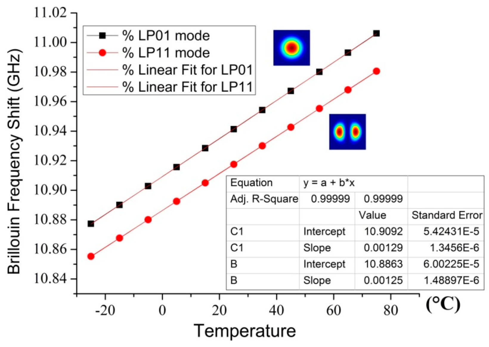
| Mode | CT (MHz/°C) | Cε (kHz/με) |
|---|---|---|
| LP01 | 1.29 | 58.5 |
| LP11 | 1.25 | 57.6 |
| T (°C) | S (με) | ||
|---|---|---|---|
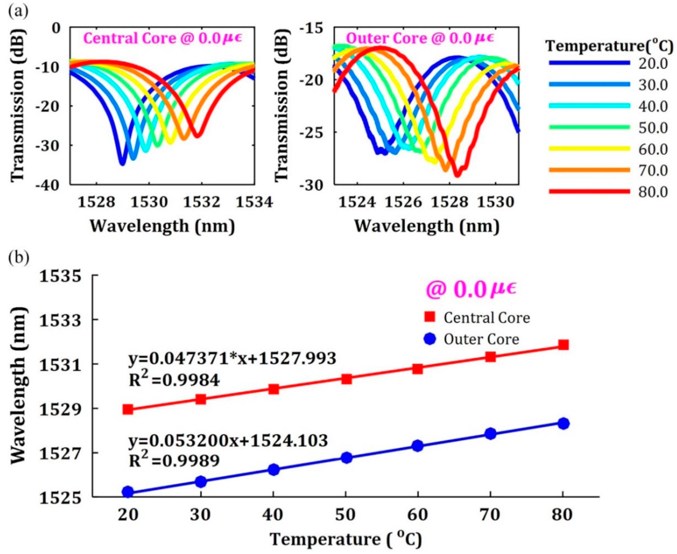
| 1528.244 | 1524.864 | 33.5 | 1210.5 |
| 1527.560 | 1524.356 | 34.3 | 1868.4 |
| Conventional Laser Spectroscopic Approach | Advanced Laser Spectroscopic Sensing System Using Screwed Modes | |
|---|---|---|
| Pros |
|
|
| Cons |
|
|
| Example of SDM-Based Sensing Systems | Corresponding Markets and Applications | Measured Parameters | Reference |
|---|---|---|---|
| Distributed sensors based on mode-division multiplexing | Civil and geotechnical structure health monitory, safety for tunnels, bridges, dams, pipelines, dikes and buildings, fire detection, well-integrity monitoring and downhole seismic acquisition | Temperature; Strain; Pressure; Stress; Force; Acoustic; Vibration; Bending; Refractive index | [14,28,38,127] |
| Distributed sensors based on core multiplexing | Oil and gas production, power cable monitoring, leakage detection at dikes and dams, integrity of liquid natural gas (LNG) carriers and terminals, railway safety monitoring | Temperature; Strain; Pressure; Stress; Vibration; Bending; Shape; Displacement | [49,80,136,137,138,139,140] |
| Fiber Bragg grating sensors based on multiplexing | Structure health monitoring of dams, highways, bridges, railways, aircraft wings, as well as spacecraft fuel tanks; pressure, displacement, or acceleration monitoring | Temperature; Strain; Pressure; Bending; Shape; Displacement; Acceleration | [84,141,142,143,144,145] |
| Whispering gallery modes for chemical species measurements | Label-free detection of macromolecules such as proteins and DNA, as well as bacteria and animal cells; temperature, pressure sensors | Temperature, Pressure, Force, Refractive Index, Species Concentration, Biochemical Compounds | [9,147,148,149,150,151,152] |
| Screw/twisted modes for examining water quality | Examining water quality, gaseous environment of the atmosphere, ice crystals; atmospheric turbulence monitoring, motion detection of various surfaces and fluids. | Species Concentration, Biochemical Compounds, Shape; Displacement; Acceleration | [53,54,55,70,71,155,156,157,158,159] |
| Optical beam shaping for improving cantilever deflection measurements | Cantilever deflection measurements, atomic force microscopes (AFM), measuring biochemical reactions via surface stress imaging and temperature fluctuations | Temperature; Species Concentration, Biochemical Compounds; Refractive Index | [10,162,163,164] |
| DTS | DAS | |
|---|---|---|
| With Multiplexing |
|
|
| Without Multiplexing |
|
|
| Corresponding Modes | Sensing Parameters | Mode Conversion Techniques | Sensing Mechanism |
|---|---|---|---|
| LP modes | Temperature; Strain; Pressure; Acoustic; Vibration; Bending; Refractive index; Humidity | Phase plates; FBG; LCoS; fused fiber coupler; FWM | Brillouin/Raman/Rayleigh scattering or spectral shift from FBG |
| Supermodes | Temperature; Strain; Acoustic; Curvature; Bending; Refractive index | Phase plates; FBG; LCoS | Using either mode/core correlation or spectral shift for sensor interrogation |
| Principle modes | Temperature; Strain; Bending | Phase plates; LPG; Spatial light modulator | Spatial modes without modal dispersion to first-order in frequency |
| Transverse modes | Temperature; Strain; Pressure; Acoustic; Bending; | Phase plates; LPG; LCoS; | Brillouin/Raman/Rayleigh scattering or spectral shift from FBG |
| Screw/twisted modes | Atmospheric turbulence monitoring; lateral motion detecting; biomedical imaging | Cylindrical lenses; Helical gratings; parametric oscillator | OAM states partially quenched due to inter-molecular interaction |
| Whispering gallery modes | Temperature, refractive index, biochemical species | Whispering gallery mode resonator in a tapered fiber | Travel around concave surfaces with low loss due to quantum tunneling |
| Modes of capillary optical fibers | Temperature; Strain; Flow rate, pulling force, fiber geometry, biochemical species | Capillary tapered mode converter | Multiple modes excited/interfered to form fringes collected by lead-out SMF |
| Corresponding Modes | Measurement Components | Benefits | References |
|---|---|---|---|
| LP modes | Using FMF, MMF, MCF itself as the sensing medium with direct/coherent detection | Simple; Compact; low loss; high sensitivity; good repeatability | [14,24,64,77,122] |
| Supermodes | A few-millimeter-long piece of seven-core fiber spliced between two single-mode fibers | Compact; low loss; high sensitivity; good repeatability | [49,67,69] |
| Principle modes | A multimode waveguide system in the vicinity of the phase-matching frequency | High speed; high sensitivity; low modal dispersion | [48,50,51] |
| Transverse modes | Using FMF, MMF, MCF itself as the sensing medium with direct/coherent detection | Compact; low loss; high sensitivity; good repeatability | [28,52,130] |
| Screw/twisted modes | Laser spectroscopic devices; atomic force microscopes; photo-sensitive detector | Higher sensitivity and selectivity; Better spectral efficiency | [53,54,55,70,71,153,154,155,156,157] |
| Whispering gallery modes | A microscopic glass sphere from micro-cavities of optical fiber resonator | High sensitivity to refractive index; useful in biochemical sensing | [56,57,72,73,147,148,149,150,151,152] |
| Modes of capillary optical fibers | A fused-silica capillary and FBG sandwiched by single-mode fibers | High sensitivity to refractive index; useful in biochemical sensing | [58,59] |
| Type of Light Sources | Wavelength Region | Output Power | Linewidth | Cost |
|---|---|---|---|---|
| Distributed feedback laser diodes (DFB lasers) | 1000 nm–1500 nm | tens of mW | several MHz | $300.00–$3,500.00 |
| Distributed Bragg reflector lasers (DBR lasers) | 1000 nm–1500 nm | tens of mW | several MHz | $500.00–$3,950.00 |
| Fabry-Perot Laser Diodes (FP lasers) | 400 nm–1550 nm | 10–300 mW | 1–2 MHz | $1,475.00–$4,000.00 |
| distributed feedback fiber lasers (DFB + FBG) | 980 nm–1550 nm | 20–150 mW | a few kHz | About $5,000.00 |
| InGaAsP/InP distributed feedback laser | 1064 nm–1560 nm | 25 mW–300 mW | 10 kHz | About $6,000.00 |
| Nd:YAG laser | 1064 nm–1550 nm | 100 mW–3 W | 10 kHz | About $10,000.00 |
| Diode-pumped solid-state bulk lasers | 1064 nm–1550 nm | 100 mW–1 W | a few kHz | About $14,900.00 |
| Distributed Feedback Quantum Cascade Lasers (QCLs) | 760 nm–1600 nm | 100 mW–5 W | a few hundred Hz | $6,200.00–$15,000.00 |
| Component Type | Components | Cost |
|---|---|---|
| Distributed feedback laser diodes (DFB lasers) | ★ | |
| Light source | Fabry-Perot laser diodes (FP lasers) | ★★ |
| Quantum cascade lasers (QCLs) | ★★★ | |
| Nd:YAG lasers | ★★★★ | |
| Long-period grating (LPG) based converter | ★ | |
| Liquid crystal on silicon (LCoS) panels | ★★ | |
| Thin phase plates | ★★ | |
| Mode converter | Helical gratings (HGs) | ★★ |
| Cylindrical lenses | ★★★ | |
| Optical parametric oscillator | ★★★ | |
| Whispering gallery mode resonator | ★★★★ | |
| Capillary tapered mode converter | ★★★★ | |
| Multiplexer | Spatial light modulators (SLM) via LCoS | ★★ |
| Photonic lantern (PL) | ★★★ | |
| LPG based multicore elements | ★★ | |
| Multicore elements | Asymmetrical coupler based multicore elements | ★★★ |
| Special fiber based multicore elements | ★★★★ | |
| Few-mode Raman amplifiers | ★★ | |
| SDM amplifiers | Few-mode erbium-doped fiber amplifiers (FM-EDFA) | ★★★ |
| Multi-core EDFAs | ★★★★ | |
| Direct detection | ★★ | |
| Detection units | Homodyne detection | ★★★★ |
| Heterodyne detection | ★★★★ |
© 2016 by the authors; licensee MDPI, Basel, Switzerland. This article is an open access article distributed under the terms and conditions of the Creative Commons Attribution (CC-BY) license (http://creativecommons.org/licenses/by/4.0/).
Share and Cite
Weng, Y.; Ip, E.; Pan, Z.; Wang, T. Advanced Spatial-Division Multiplexed Measurement Systems Propositions—From Telecommunication to Sensing Applications: A Review. Sensors 2016, 16, 1387. https://doi.org/10.3390/s16091387
Weng Y, Ip E, Pan Z, Wang T. Advanced Spatial-Division Multiplexed Measurement Systems Propositions—From Telecommunication to Sensing Applications: A Review. Sensors. 2016; 16(9):1387. https://doi.org/10.3390/s16091387
Chicago/Turabian StyleWeng, Yi, Ezra Ip, Zhongqi Pan, and Ting Wang. 2016. "Advanced Spatial-Division Multiplexed Measurement Systems Propositions—From Telecommunication to Sensing Applications: A Review" Sensors 16, no. 9: 1387. https://doi.org/10.3390/s16091387