
Applying High-Speed Vision Sensing to an Industrial Robot for High-Performance Position Regulation under Uncertainties


Abstract
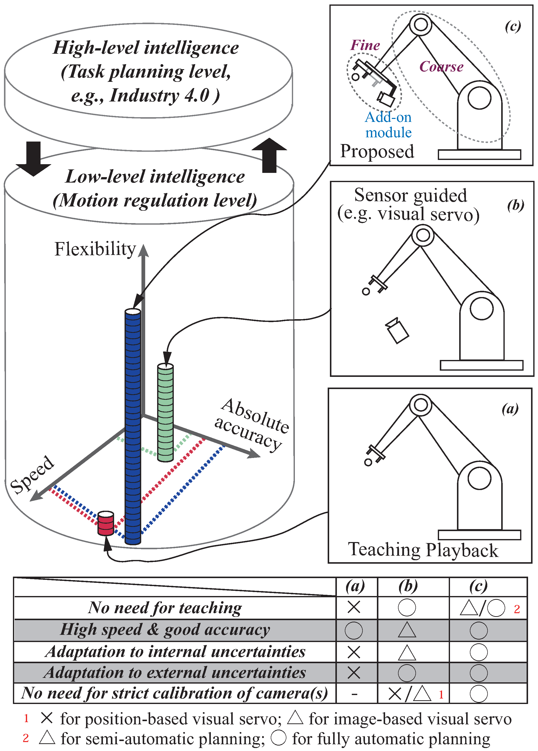
:1. Introduction
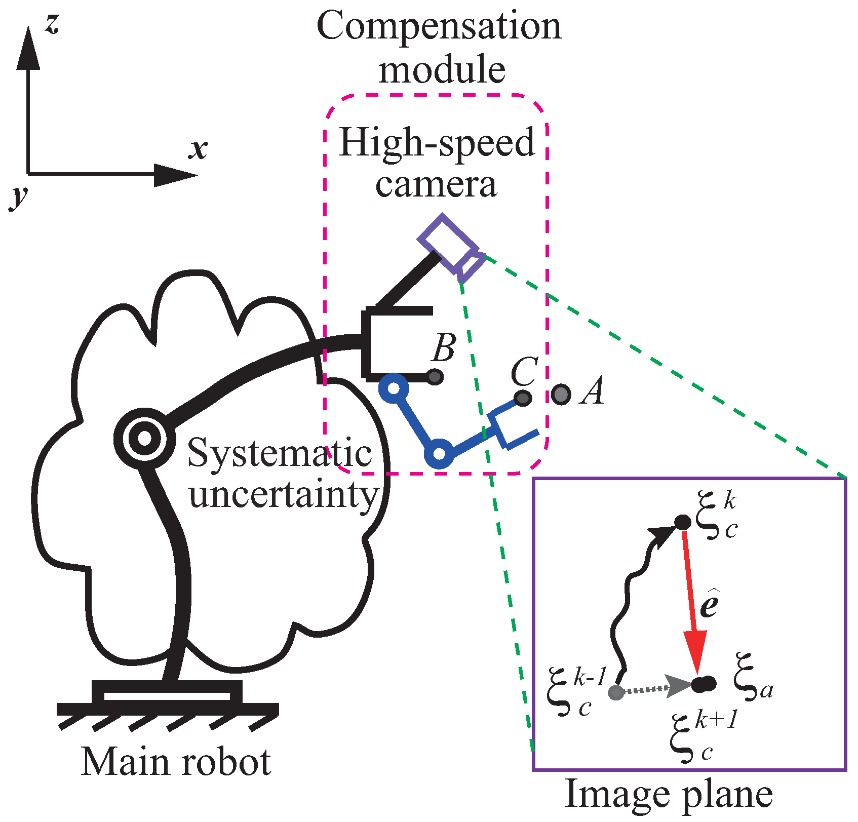
2. Proposed Method
2.1. Intuitive Analysis of Dynamic Compensation Method
- The method here decouples the direct-driven compensation module and the main industrial robot, and requires no changes to the main robot’s controller. On the contrary, traditional adaptive control methods need to directly assess the inner loop of a robot’s controller (mostly not open), which is usually considered difficult both technically and practically.
- It is difficult for traditional adaptive control methods to realize high-speed and accurate adaptive regulation due to the main robot’s large inertia and complex nonlinear dynamics. With the philosophy of motion decoupling as well as adopting high-speed vision to sense the accumulated uncertainties, the proposed method here enables a poor-accuracy industrial robot to realize high-speed and accurate position regulation by incorporating a ready-to-use add-on module.
- The compensation module should be controlled accurately and sufficiently fast. Ideally, it has a much larger bandwidth than that of the main robot.
- The visual feedback should be high speed in order to satisfy the assumption .
- The error value e is the relative information between the robot’s tool point and the target in image coordinates, which can be observed directly.
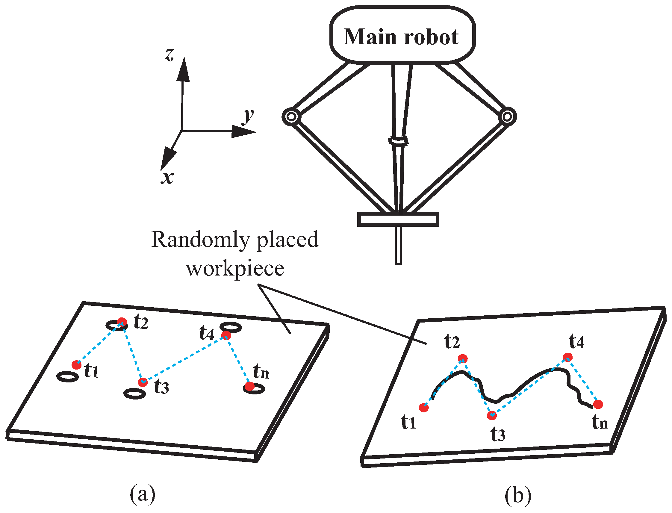
2.2. Motion Planning for the Main Robot’s Coarse Position Regulation
3. Application Scenario: Dynamic Peg-and-Hole Alignment
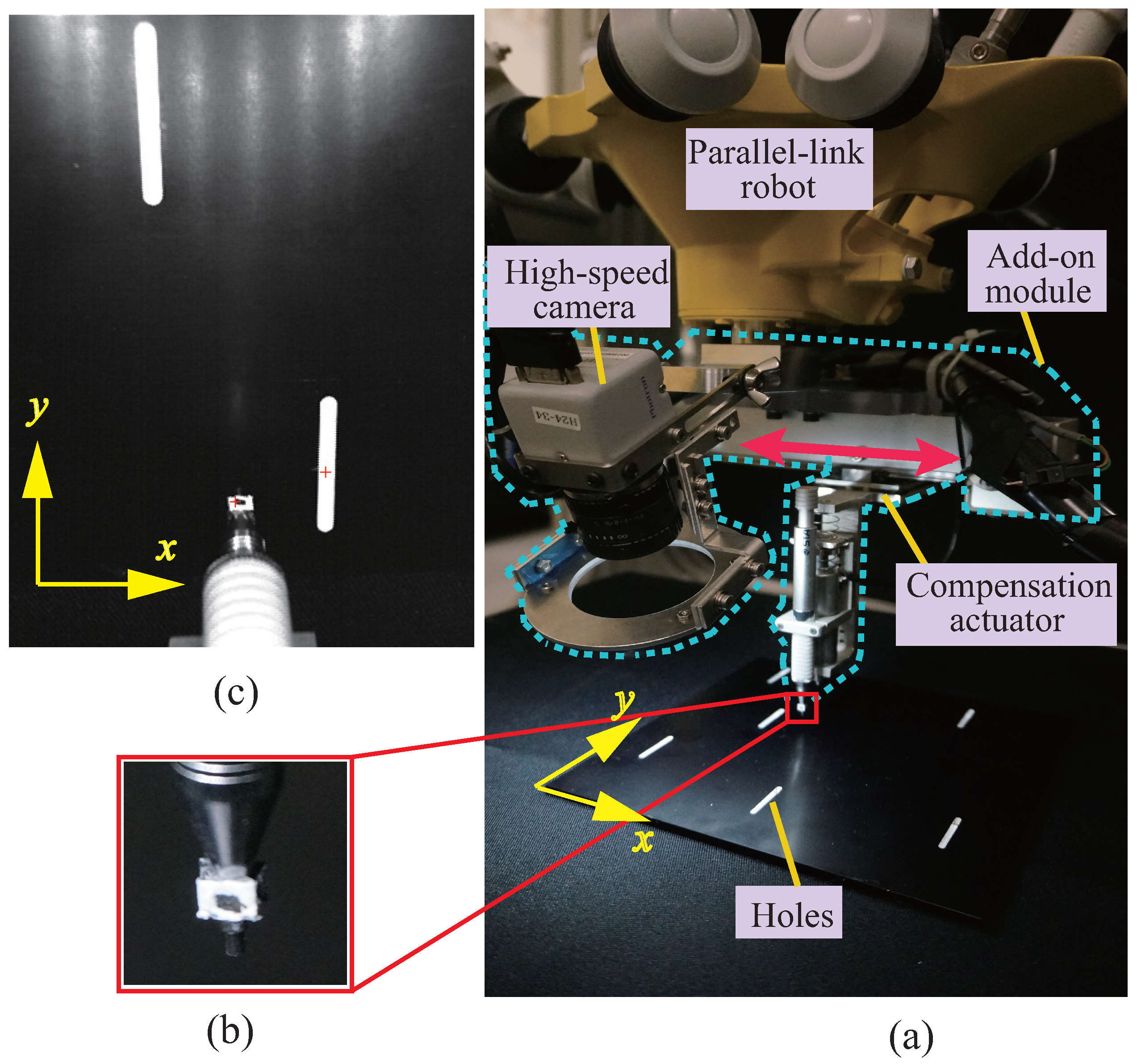
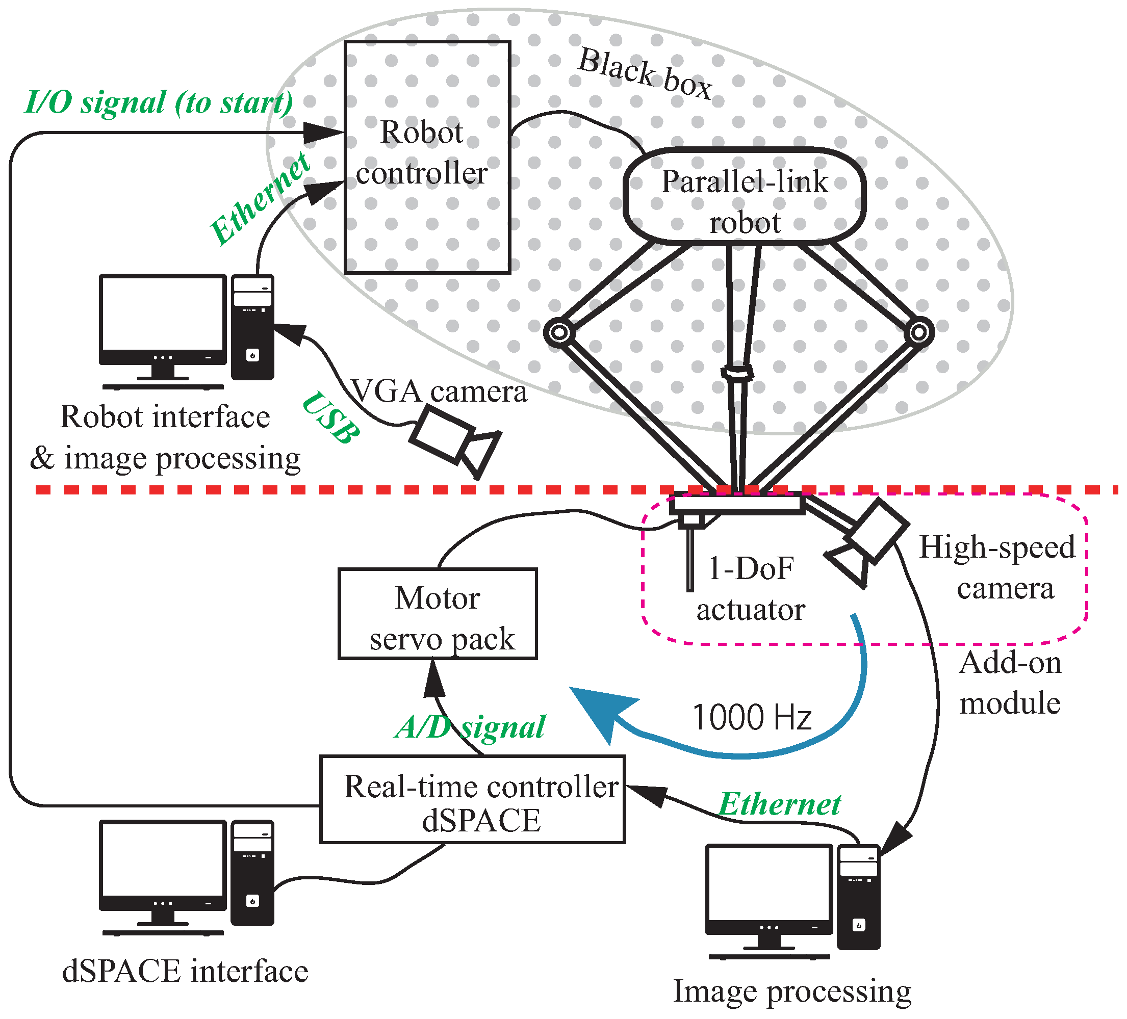
3.1. Task Illustration and Experimental System
3.1.1. Robot Systems
3.1.2. High-Speed Vision Sensing
3.2. Fully Automatic Motion Planning of the Main Robot
3.2.1. Simple Calibration Procedure
3.2.2. Hole Detection and Trajectory Planning
3.3. Fine Compensation of the Add-on Module
3.4. Experimental Results
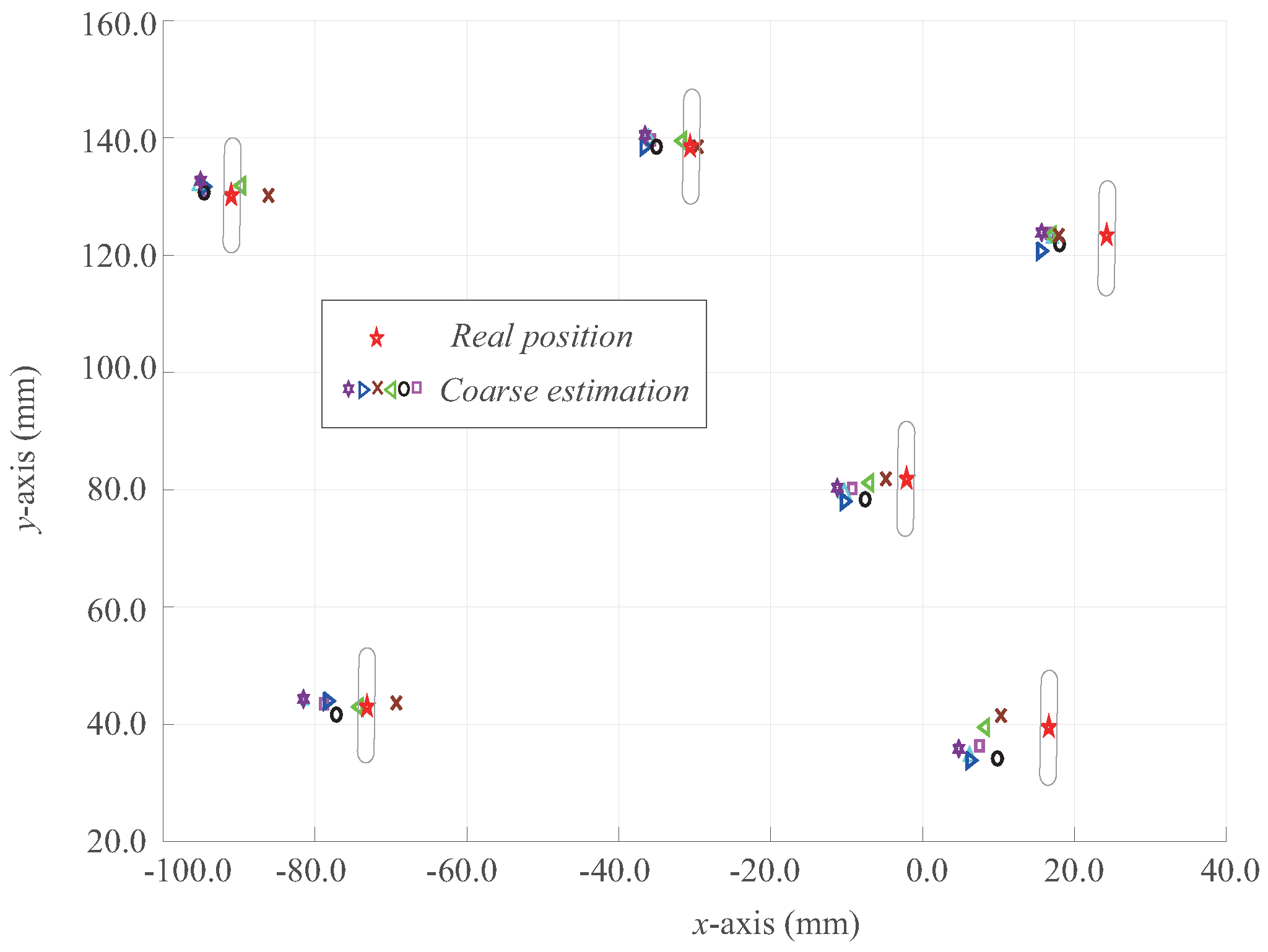
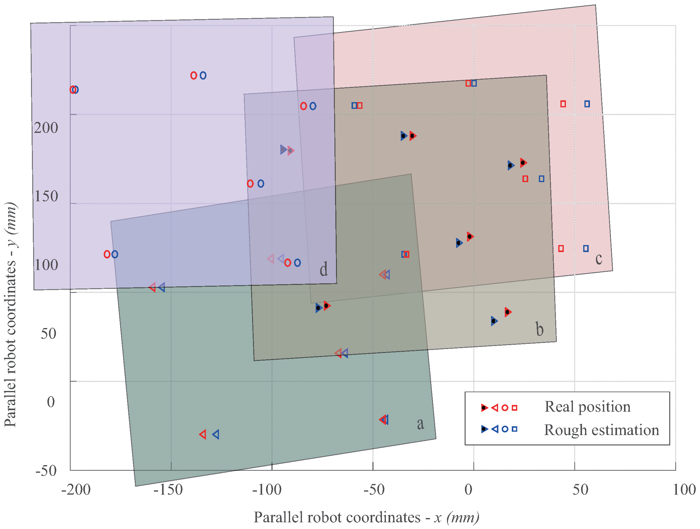
3.4.1. Evaluation of Coarse Motion Planning
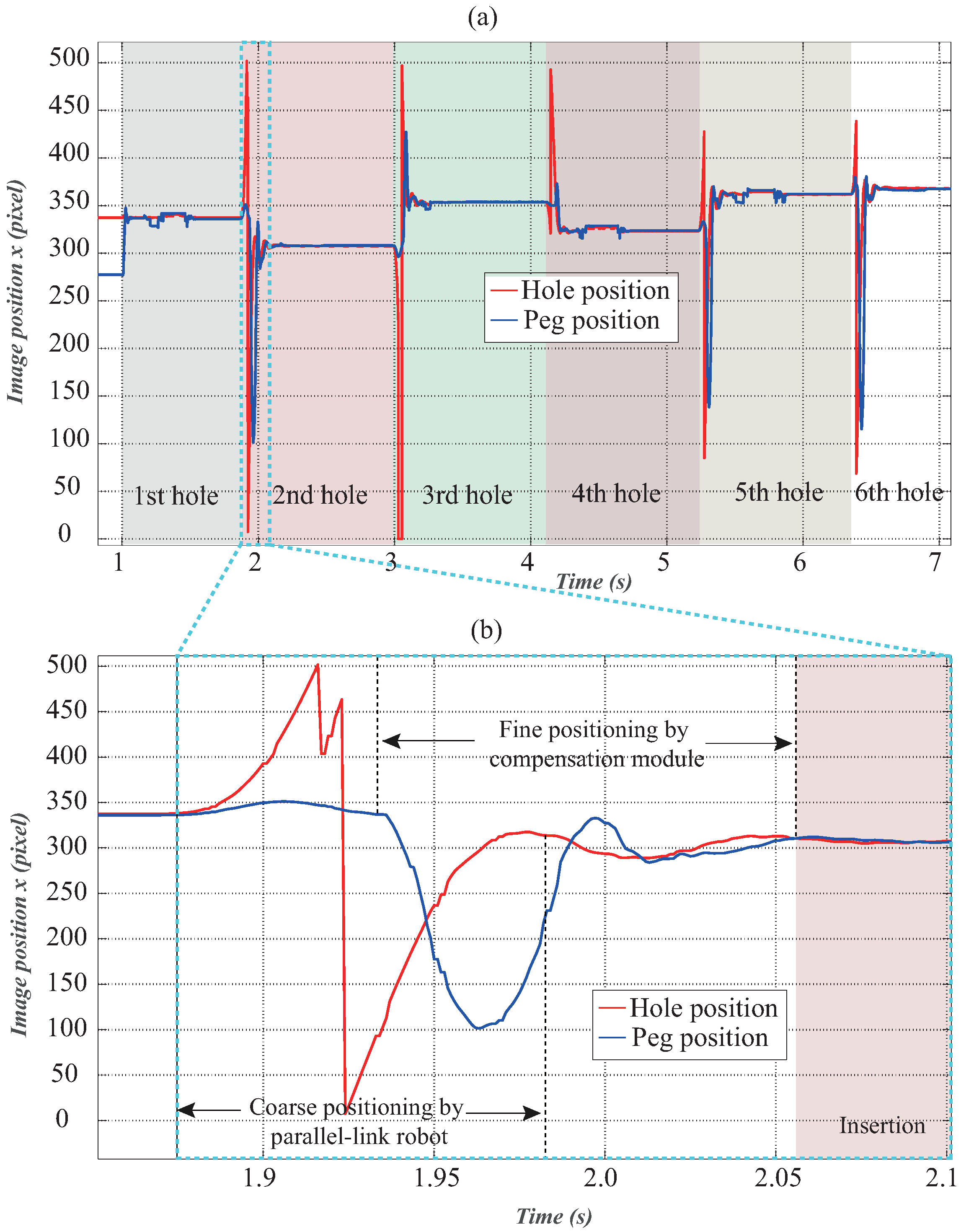
3.4.2. Result of Dynamic Peg-and-Hole Alignment
3.4.3. Discussion
4. Conclusions
Author Contributions
Conflicts of Interest
References
- Verdonck, W.; Swevers, J. Improving the Dynamic Accuracy of Industrial Robots by Trajectory Pre-Compensation. In Proceedings of the 2002 IEEE International Conference on Robotics and Automation, Washington, DC, USA, 12–18 May 2002; pp. 3423–3428.
- Maeda, Y.; Nakamura, T. View-based teaching/playback for robotic manipulation. ROBOMECH J. 2015, 2, 1–12. [Google Scholar] [CrossRef]
- Cheah, C.C.; Lee, K.; Kawamura, S.; Arimoto, S. Asymptotic Stability of Robot Control with Approximate Jacobian Matrix and its Application to Visual Servoing. In Proceedings of the 39th IEEE Conference on Decision and Control, Sydney, Australia, 12–15 December 2000; pp. 3939–3944.
- Cheah, C.C.; Hirano, M.; Kawamura, S.; Arimoto, S. Approximate jacobian control for robots with uncertain kinematics and dynamics. IEEE Trans. Robot. Autom. 2003, 19, 692–702. [Google Scholar] [CrossRef]
- Zergeroglu, E.; Dawson, D.M.; de Queiroz, M.S.; Setlur, P. Robust visual-servo control of robot manipulators in the presence of uncertainty. J. Robot. Syst. 2003, 20, 93–106. [Google Scholar] [CrossRef]
- Piepmeier, J.A.; McMurray, G.V.; Lipkin, H. Uncalibrated dynamic visual servoing. IEEE Trans. Robot. Autom. 2004, 20, 143–147. [Google Scholar] [CrossRef]
- Liu, Y.H.; Wang, H.; Wang, C.; Lam, K.K. Uncalibrated visual servoing of robots using a depth-independent interaction matrix. IEEE Trans. Robot. 2006, 22, 804–817. [Google Scholar]
- Wang, H.; Liu, Y.H.; Zhou, D. Adaptive visual servoing using point and line features with an uncalibrated eye-in-hand camera. IEEE Trans. Robot. 2008, 24, 843–856. [Google Scholar] [CrossRef]
- Bauchspiess, A.; Alfaro, S.C.A.; Dobrzanski, L.A. Predictive sensor guided robotic manipulators in automated welding cells. J. Mater. Process. Technol. 2001, 9, 13–19. [Google Scholar] [CrossRef]
- Huang, S.; Yamakawa, Y.; Senoo, T.; Ishikawa, M. Dynamic compensation by fusing a high-speed actuator and high-speed visual feedback with its application to fast peg-and-hole alignment. Adv. Robot. 2014, 28, 613–624. [Google Scholar] [CrossRef]
- Industry 4.0. Available online: https://en.wikipedia.org/wiki/Industry_4.0 (accessed on 4 May 2016).
- Sharon, A.; Hogan, N.; Hardt, E.D. The macro/micro manipulator: An improved architecture for robot control. Robot. Comput. Integr. Manuf. 1993, 10, 209–222. [Google Scholar] [CrossRef]
- Lew, J.Y.; Trudnowski, D.J. Vibration control of a micro/macro-manipulator system. IEEE Control Syst. Mag. 1996, 16, 26–31. [Google Scholar] [CrossRef]
- Arakawa, K.; Kakizaki, T.; Omyo, S. A Method of Robust Seam Feature Detection from Profiles for Robotic Sealing. In Proceedings of the MVA1998 IAPR Workshop on Machine Vision Applications, Chiba, Japan, 17–19 November 1998; pp. 81–84.
- Hodac, A.; Siegwart, R. Decoupled Macro/Micro-Manipulator for Fast and Precise Assembly Operations: Design and Experiments. In Proceedings of the SPIE 3834, Microrobotics and Microassembly, Boston, MA, USA, 18 August 1999; pp. 122–130.
- Schneider, U.; Olofsson, B.; Sornmo, O.; Drusta, M.; Robertssonb, A.; Hägelea, M.; Johansson, R. Integrated approach to robotic machining with macro/micro-actuation. Robot. Comput. Integr. Manuf. 2014, 30, 636–647. [Google Scholar] [CrossRef]
- Omari, A.; Ming, A.; Nakamura, S.; Kanamori, C.; Kajitani, M. Development of a high-precision mounting robot with fine motion mechanism (3rd report)—Positioning experiment of scara robot with fine mechanism. Jpn. Soc. Precis. Eng. 2001, 67, 1101–1107. [Google Scholar] [CrossRef]
- Huang, S.; Bergström, N.; Yamakawa, Y.; Senoo, T.; Ishikawa, M. High-Performance Robotic Contour Tracking Based on the Dynamic Compensation Concept. In Proceedings of the 2016 IEEE International Conference on Robotics and Automation, Stockholm, Sweden, 16–21 May 2016; pp. 3886–3893.
- Photron IDP-Express R2000 High-Speed Camera. Available online: http://www.photron.co.jp/ (accessed on 4 May 2016).
- CUDA Parallel Computing Platform. Available online: http://www.nvidia.com/object/cuda_home_new.html (accessed on 12 June 2016).
- Hartley, R.I.; Zisserman, A. Multiple View Geometry in Computer Vision; Cambridge University Press: Cambridge, UK, 2004. [Google Scholar]
- Lawler, E.L.; Lenstra, J.K.; Rinnooy Kan, A.H.G.; Shmoys, D.B. The Traveling Salesman Problem: A Guided Tour of Combinatorial Optimization; John Wiley and Sons Ltd.: Chichester, UK, 1985. [Google Scholar]
- Huang, S.; Yamakawa, Y.; Senoo, T.; Ishikawa, M. A pre-compensation fuzzy logic algorithm designed for the dynamic compensation robotic system. Int. J. Adv. Robot. 2015, 12, 1–12. [Google Scholar] [CrossRef]
- Video for Experimental Result of Peg-and-Hole Alignment. Available online: http://www.k2.t.u-tokyo.ac.jp/fusion/pih/index-e.html (accessed on 19 June 2016).


| Stroke | Maximum Velocity | Maximum Acceleration | Weight |
|---|---|---|---|
| 100 mm | 1.6 m/s | 200 m/s2 | 0.86 kg |
| Hole Number | Pose a | Pose b | Pose c | Pose d | |
|---|---|---|---|---|---|
| 1 | Real | −134.017 | −34.608 | −181.741 | −73.185 |
| Estimation | −127.544 | −33.456 | −177.837 | −77.154 | |
| Error | 6.473 | 1.152 | 3.904 | −3.969 | |
| 2 | Real | −44.895 | 55.573 | −92.3 | 16.625 |
| Estimation | −43.554 | 43.335 | −87.308 | 9.838 | |
| Error | 1.341 | −12.238 | 4.992 | −6.787 | |
| 3 | Real | −66.912 | 33.529 | −110.702 | −2.103 |
| Estimation | −63.58 | 25.579 | −105.454 | −7.514 | |
| Error | 3.332 | −7.95 | 5.248 | −5.411 | |
| 4 | Real | −44.886 | 56.154 | −84.365 | 24.235 |
| Estimation | −42.865 | 44.194 | −79.821 | 18.003 | |
| Error | 2.021 | −11.96 | 4.544 | −6.232 | |
| 5 | Real | −100.314 | 0.154 | −138.715 | −30.644 |
| Estimation | −95.282 | −2.808 | −134.139 | −35.014 | |
| Error | 5.032 | −2.962 | 4.576 | −4.37 | |
| 6 | Real | −158.974 | −59.192 | −198.655 | −90.696 |
| Estimation | −154.371 | −56.455 | −197.503 | −94.610 | |
| Error | 4.603 | 2.737 | 1.152 | −3.914 | |
© 2016 by the authors; licensee MDPI, Basel, Switzerland. This article is an open access article distributed under the terms and conditions of the Creative Commons Attribution (CC-BY) license (http://creativecommons.org/licenses/by/4.0/).
Share and Cite
Huang, S.; Bergström, N.; Yamakawa, Y.; Senoo, T.; Ishikawa, M. Applying High-Speed Vision Sensing to an Industrial Robot for High-Performance Position Regulation under Uncertainties. Sensors 2016, 16, 1195. https://doi.org/10.3390/s16081195
Huang S, Bergström N, Yamakawa Y, Senoo T, Ishikawa M. Applying High-Speed Vision Sensing to an Industrial Robot for High-Performance Position Regulation under Uncertainties. Sensors. 2016; 16(8):1195. https://doi.org/10.3390/s16081195
Chicago/Turabian StyleHuang, Shouren, Niklas Bergström, Yuji Yamakawa, Taku Senoo, and Masatoshi Ishikawa. 2016. "Applying High-Speed Vision Sensing to an Industrial Robot for High-Performance Position Regulation under Uncertainties" Sensors 16, no. 8: 1195. https://doi.org/10.3390/s16081195
APA StyleHuang, S., Bergström, N., Yamakawa, Y., Senoo, T., & Ishikawa, M. (2016). Applying High-Speed Vision Sensing to an Industrial Robot for High-Performance Position Regulation under Uncertainties. Sensors, 16(8), 1195. https://doi.org/10.3390/s16081195