
A Wireless 32-Channel Implantable Bidirectional Brain Machine Interface

Abstract
:1. Introduction
2. Bidirectional BMI Design Challenges
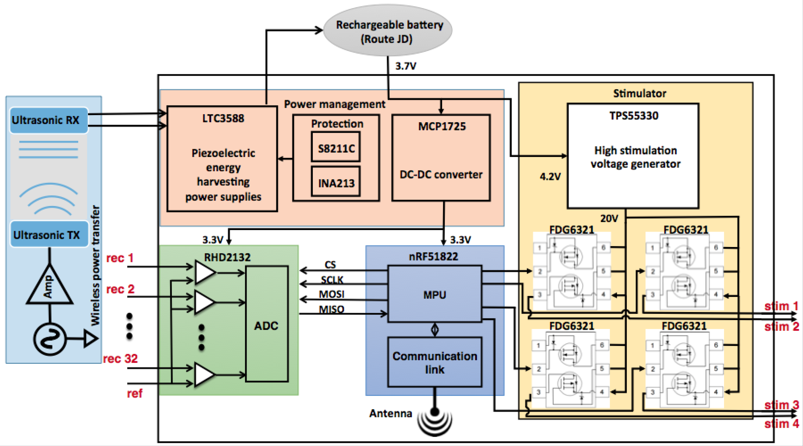
3. The Bidirectional BMI System Design
3.1. Electrode
3.2. Sense Electronics Module
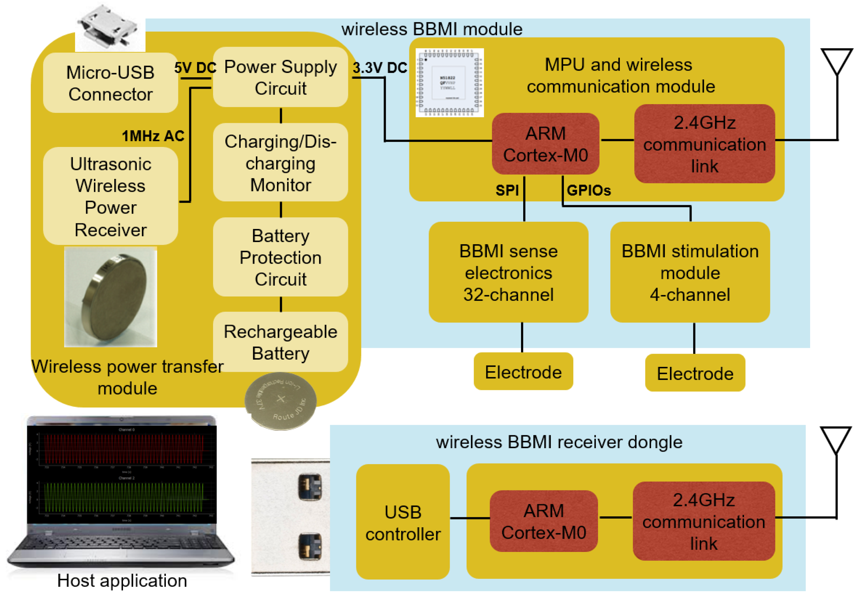
3.3. MPU and Wireless Communication Module
3.4. Stimulation Module
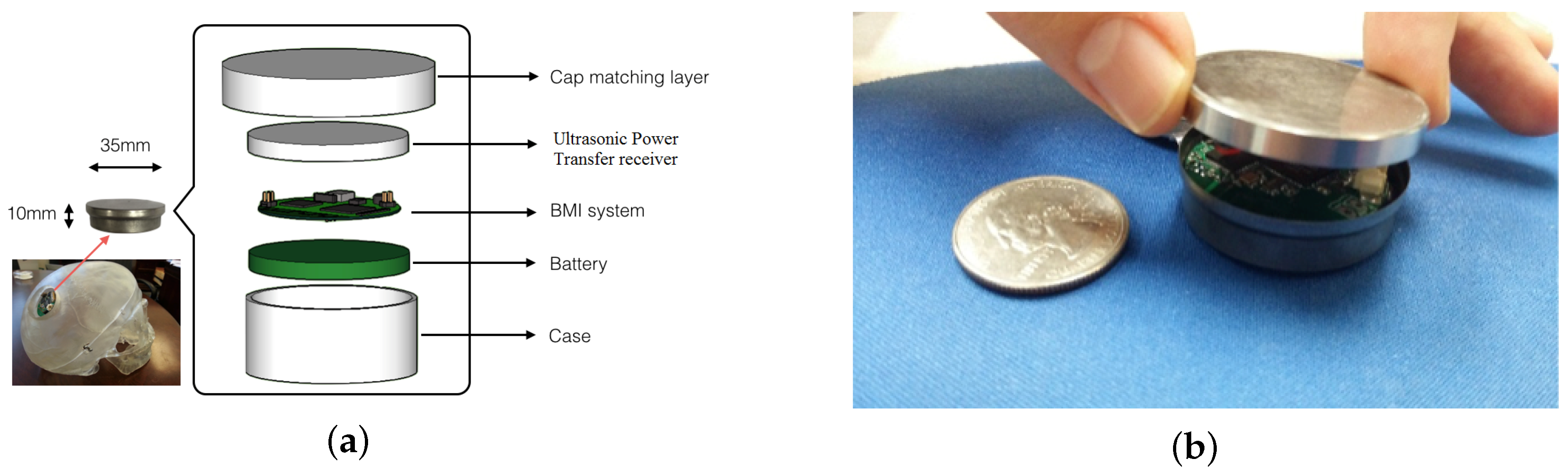
4. Wireless Power Transfer and Power Budget
5. Experiment Setup and Results
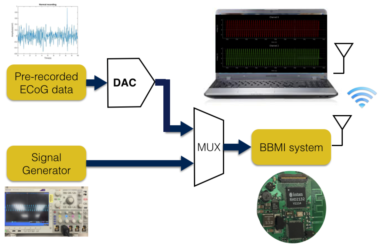
5.1. Bench Test
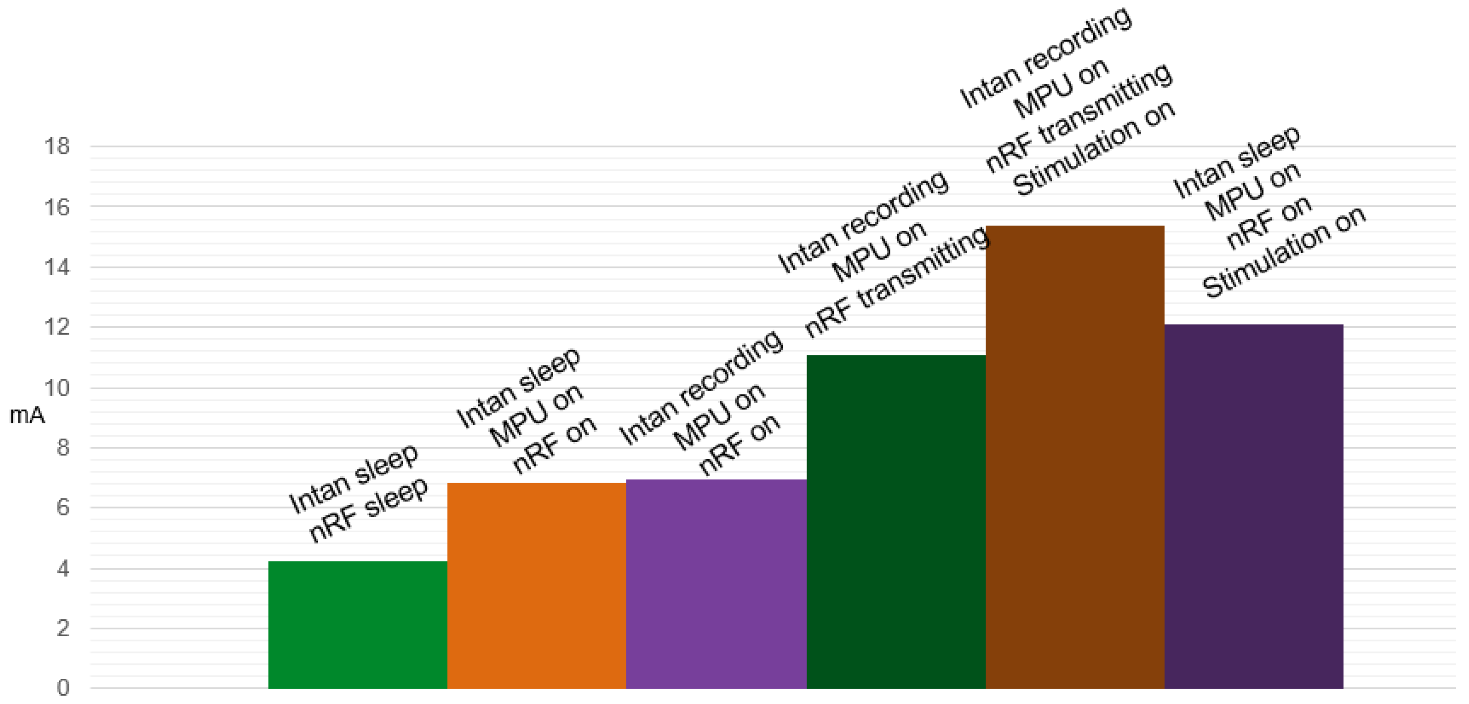
5.2. Power Analysis
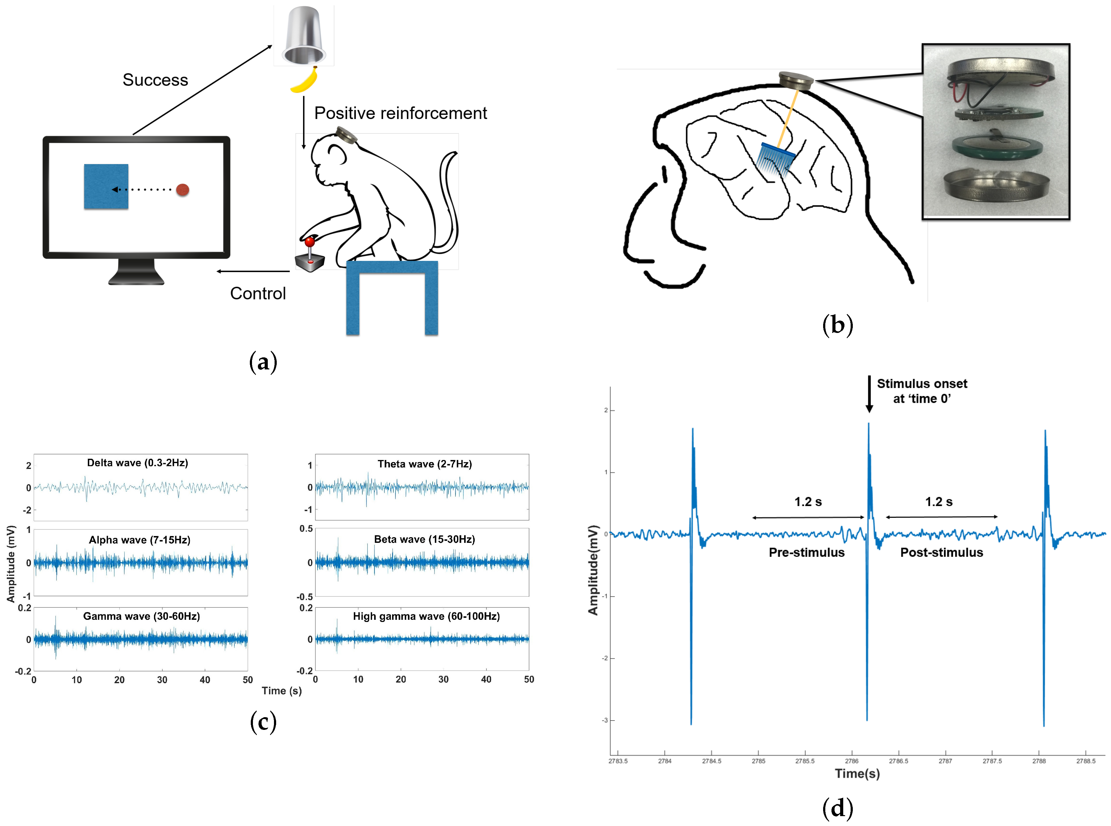
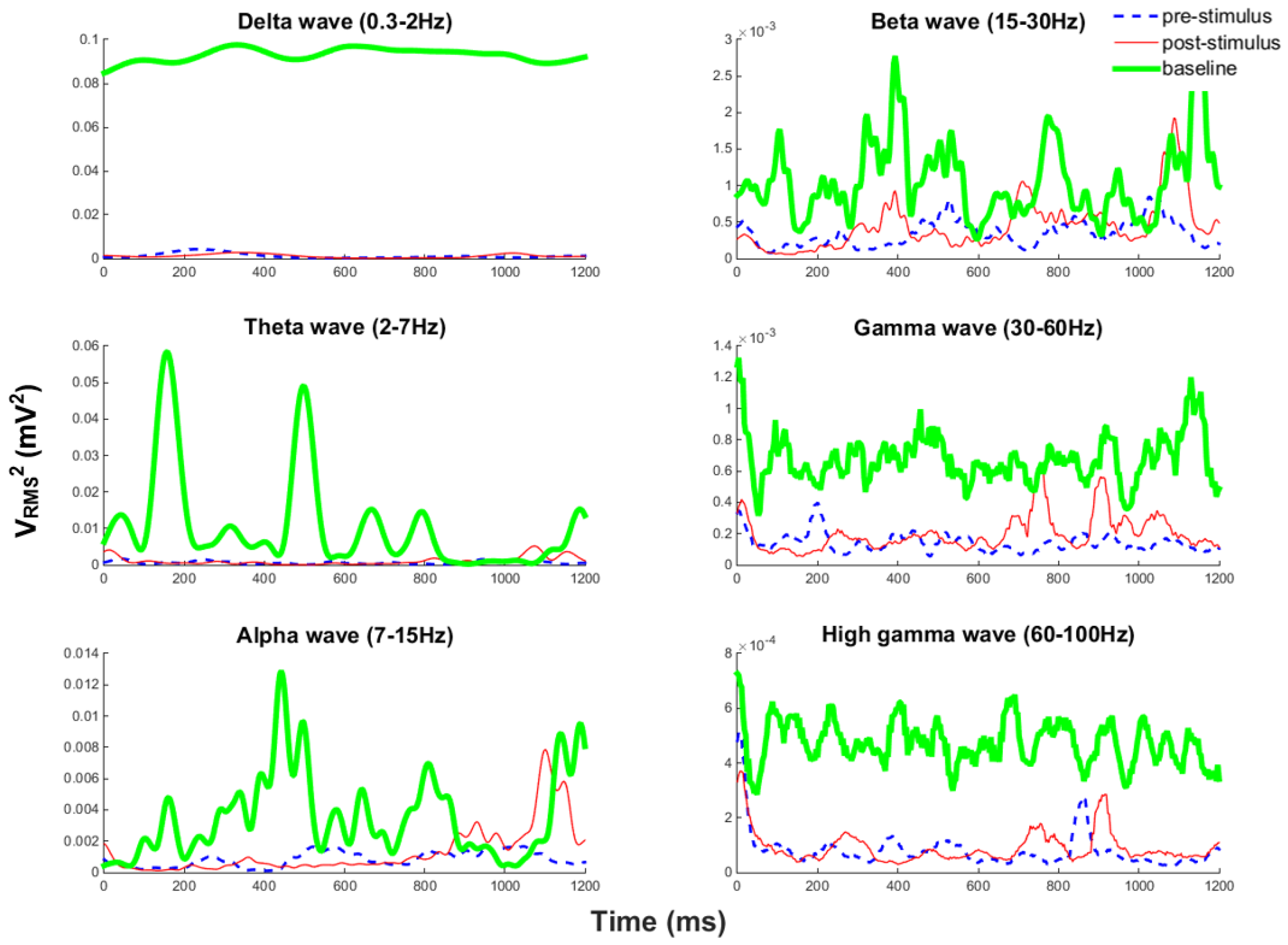
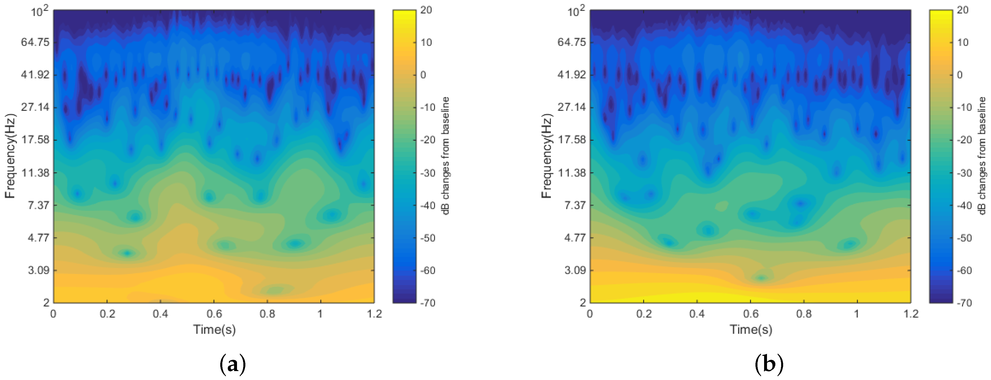
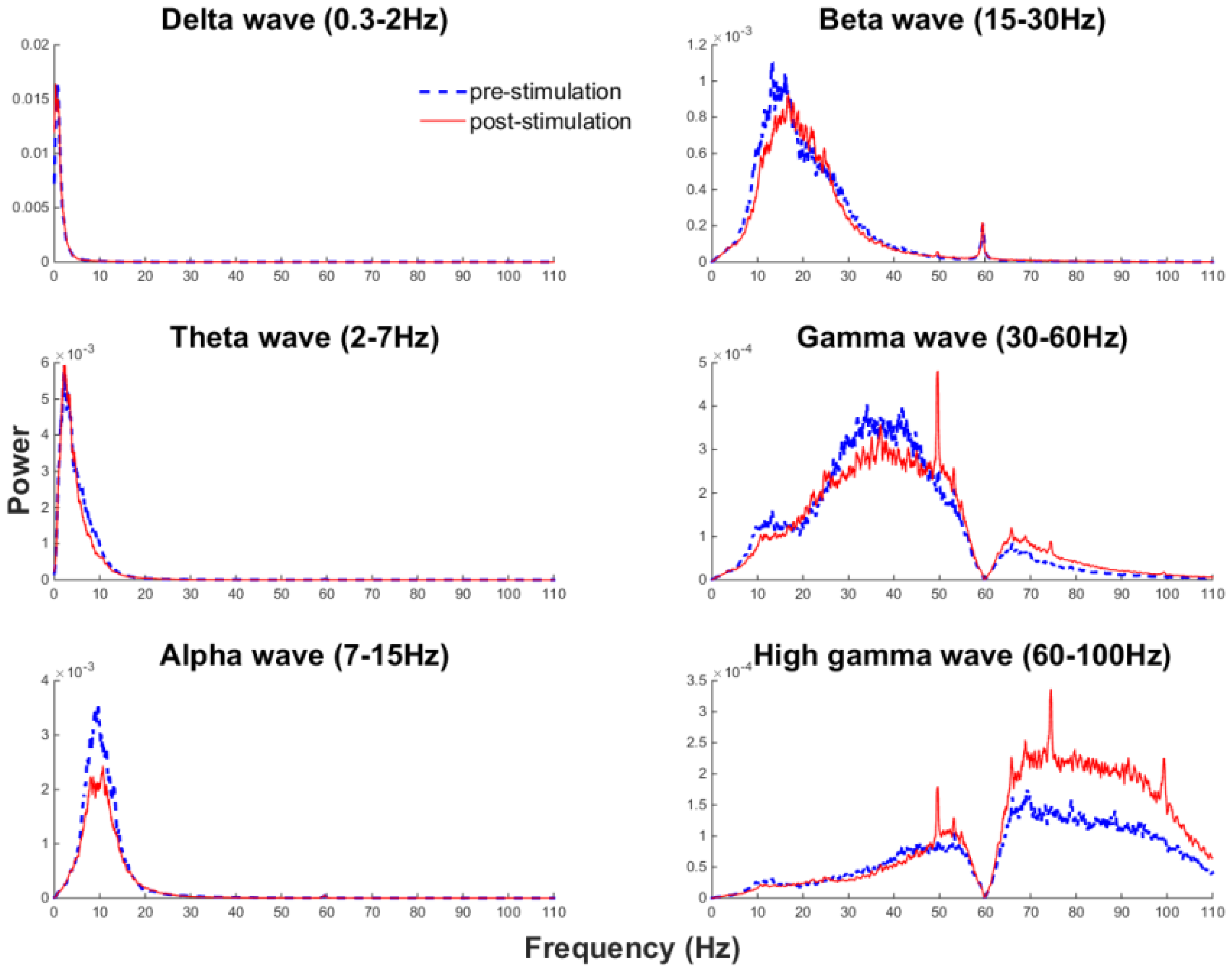
5.3. In Vivo Test
6. Discussion and Conclusion
Acknowledgments
Author Contributions
Conflicts of Interest
References
- Pascual-Leone, A.; Amedi, A.; Fregni, F.; Merabet, L. The Plastic Human Brain Cortex. Annu. Rev. Neurosci. 2005, 28, 377–401. [Google Scholar] [CrossRef] [PubMed]
- Jang, S.H.; Kim, Y.H.; Cho, S.H.; Chang, Y.; Lee, Z.I.; Ha, J.S. Cortical reorganization associated with motor recovery in hemiparetic stroke patients. Neuroreport 2003, 14, 1305–1310. [Google Scholar] [CrossRef] [PubMed]
- Moore, C.I.; Stern, C.E.; Dunbar, C.; Kostyk, S.K.; Gehi, A.; Corkin, S. Referred phantom sensations and cortical reorganization after spinal cord injury in humans. Proc. Natl. Acad. Sci. USA 2000, 97, 14703–14708. [Google Scholar] [CrossRef] [PubMed]
- Ding, Y.M.; Kastin, A.J.; Pan, W.H. Neural plasticity after spinal cord injury. Curr. Pharm. Des. 2005, 11, 1441–1450. [Google Scholar] [CrossRef] [PubMed]
- Song, Y.K.; Borton, D.A.; Park, S.; Patterson, W.R.; Bull, C.W.; Laiwalla, F.; Mislow, J.; Simeral, J.D.; Donoghue, J.P.; Nurmikko, A.V. Active Microelectronic Neurosensor Arrays for Implantable Brain Communication Interfaces. IEEE Trans. Neural Syst. Rehabil. Eng. 2009, 17, 339–345. [Google Scholar] [CrossRef] [PubMed]
- Collinger, J.L.; Wodlinger, B.; Downey, J.E.; Wang, W.; Tyler-Kabara, E.C.; Weber, D.J.; McMorland, A.J.C.; Velliste, M.; Boninger, M.L.; Schwartz, A.B. High-performance neuroprosthetic control by an individual with tetraplegia. Lancet 2013, 381, 557–564. [Google Scholar] [CrossRef]
- Hirata, M.; Matsushita, K.; Suzuki, T.; Yoshida, T.; Sato, F.; Morris, S.; Yanagisawa, T.; Goto, T.; Kawato, M.; Yoshimine, T. A fully-implantable wireless system for human brain-machine interfaces using brain surface electrodes: W-HERBS. IEICE Trans. Commun. 2011, E94-B, 2448–2453. [Google Scholar] [CrossRef]
- Mestais, C.S.; Charvet, G.; Sauter-Starace, F.; Foerster, M.; Ratel, D.; Benabid, A.L. WIMAGINE: Wireless 64-channel ECoG recording implant for long term clinical applications. IEEE Trans. Neural Syst. Rehabil. Eng. 2015, 23, 10–21. [Google Scholar] [CrossRef] [PubMed]
- Zanos, S.; Richardson, A.G.; Shupe, L.; Miles, F.P.; Fetz, E.E. The neurochip-2: An autonomous head-fixed computer for recording and stimulating in freely behaving monkeys. IEEE Trans. Neural Syst. Rehabil. Eng. 2011, 19, 427–435. [Google Scholar] [CrossRef] [PubMed]
- Nguyen, T.K.T.; Navratilova, Z.; Cabral, H.; Wang, L.; Gielen, G.; Battaglia, F.P.; Bartic, C. Closed-loop optical neural stimulation based on a 32-channel low-noise recording system with online spike sorting. J. Neural Eng. 2014, 11. [Google Scholar] [CrossRef] [PubMed]
- Liu, X.; Zhang, M.; Subei, B.; Richardson, A.G.; Lucas, T.H.; van der Spiegel, J. The PennBMBI: Design of a general purpose wireless brain-machine-brain interface system. IEEE Trans. Biomed. Circuits Syst. 2015, 9, 248–258. [Google Scholar] [CrossRef] [PubMed]
- Angotzi, G.N.; Boi, F.; Zordan, S.; Bonfanti, A.; Vato, A. A programmable closed-loop recording and stimulating wireless system for behaving small laboratory animals. Sci. Rep. 2014, 4. [Google Scholar] [CrossRef] [PubMed]
- Gagnon-Turcotte, G.; LeChasseur, Y.; Bories, C.; De Koninck, Y.; Gosselin, B. A Wireless Optogenetic Headstage with Multichannel Neural Signal Compression. In Proceedings of the 2015 IEEE Biomedical Circuits and Systems Conference (BioCAS), Atlanta, GA, USA, 22–24 October 2015.
- Wei, P.; He, W.; Zhou, Y.; Wang, L. Performance of Motor Imagery Brain-Computer Interface Based on Anodal Transcranial Direct Current Stimulation Modulation. IEEE Trans. Neural Syst. Rehabil. Eng. 2013, 21, 404–415. [Google Scholar] [PubMed]
- Lee, S.Q.; Youm, W.; Hwang, G.; Moon, K.S.; Ozturk, Y. Resonant ultrasonic wireless power transmission for bio-implants. SPIE Proc. 2014, 9057. [Google Scholar] [CrossRef]
- Harrison, R.R.; Kier, R.J.; Chestek, C.A.; Gilja, V.; Nuyujukian, P.; Ryu, S.; Greger, B.; Solzbacher, F.; Shenoy, K.V. Wireless Neural Signal Acquisition with Single Low-Power Integrated Circuit. IEEE Trans. Neural Syst. Rehabil. Eng. 2009, 17, 322–329. [Google Scholar] [CrossRef] [PubMed]
- Leuthardt, E.C.; Freudenberg, Z.; Bundy, D.; Roland, J. Microscale recording from human motor cortex: Implications for minimally invasive electrocorticographic brain-computer interfaces. Neurosurg. Focus 2009, 27, 1–14. [Google Scholar] [CrossRef] [PubMed]
- Miranda, H.; Gilja, V.; Chestek, C.A.; Shenoy, K.V.; Meng, T.H. HermesD: A High-Rate Long-Range Wireless Transmission System for Simultaneous Multichannel Neural Recording Applications. IEEE Trans. Biomed. Circuits Syst. 2010, 4, 181–191. [Google Scholar] [CrossRef] [PubMed]
- Schalk, G.; Leuthardt, E.C. Brain-computer interfaces using electrocorticographic signals. IEEE Rev. Biomed. Eng. 2011, 4, 140–154. [Google Scholar] [CrossRef] [PubMed]
- Borton, D.A.; Yin, M.; Aceros, J.; Nurmikko, A. An implantable wireless neural interface for recording cortical circuit dynamics in moving primates. J. Neural Eng. 2013, 10. [Google Scholar] [CrossRef] [PubMed]
- Sodagar, A.M.; Wise, K.D.; Najafi, K. A wireless implantable microsystem for multichannel neural recording. IEEE Trans. Microw. Theory Tech. 2009, 57, 2565–2573. [Google Scholar] [CrossRef]
- Mirzaei, M.; Salam, M.T.; Nguyen, D.K.; Sawan, M. A fully-asynchronous low-power implantable seizure detector for self-triggering treatment. IEEE Trans. Biomed. Circuits Syst. 2013, 7, 563–572. [Google Scholar] [CrossRef] [PubMed]
- Park, S.; Borton, D.A.; Kang, M.; Nurmikko, A.V.; Song, Y.K. An implantable neural sensing microsystem with fiber-optic data transmission and power delivery. Sensors 2013, 13, 6014–6031. [Google Scholar] [CrossRef] [PubMed]
- Yin, M.; Borton, D.A.; Aceros, J.; Patterson, W.R.; Nurmikko, A.V. A 100-channel hermetically sealed implantable device for chronic wireless neurosensing applications. IEEE Trans. Biomed. Circuits Syst. 2013, 7, 115–128. [Google Scholar] [PubMed]
- Sawan, M.; Salam, M.T.; Le Lan, J.; Kassab, A.; Gelinas, S.; Vannasing, P.; Lesage, F.; Lassonde, M.; Nguyen, D.K. Wireless recording systems: From noninvasive EEG-NIRS to invasive EEG devices. IEEE Trans. Biomed. Circuits Syst. 2013, 7, 186–195. [Google Scholar] [CrossRef] [PubMed]
- Nurmikko, A.V.; Donoghue, J.P.; Hochberg, L.R.; Patterson, W.R.; Song, Y.k.; Bull, C.W.; Borton, D.A.; Laiwalla, F.; Park, S.; Ming, Y.; et al. Listening to Brain Microcircuits for Interfacing With External World V Progress in Wireless Implantable Microelectronic Neuroengineering Devices. Proc. IEEE 2010, 98, 375–388. [Google Scholar] [CrossRef] [PubMed]
- Charvet, G.; Sauter-Starace, F.; Foerster, M.; Ratel, D.; Chabrol, C.; Porcherot, J.; Robinet, S.; Reverdy, J.; D’Errico, R.; Mestais, C.; et al. WIMAGINE®: 64-channel ECoG recording implant for human applications. In Proceedings of the 2013 35th Annual International Conference of the IEEE Engineering in Medicine and Biology Society (EMBC), Osaka, Japan, 3–7 July 2013; pp. 2756–2759.
- Wolf, P.D. Thermal Considerations for the Design of an Implanted Cortical Brain–Machine Interface (BMI). In Indwelling Neural Implants Strategy Contending with vivo Environvironment; Taylor & Francis: Boca Raton, FL, USA, 2008; pp. 63–88. [Google Scholar]
- Lee, J.; Rhew, H.G.; Kipke, D.R.; Flynn, M.P. A 64 channel programmable closed-loop neurostimulator with 8 channel neural amplifier and logarithmic ADC. IEEE J. Solid-State Circuits 2010, 45, 1935–1945. [Google Scholar] [CrossRef]
- Shahrokhi, F.; Abdelhalim, K.; Serletis, D.; Carlen, P.L.; Genov, R. The 128-channel fully differential digital integrated neural recording and stimulation interface. IEEE Trans. Biomed. Circuits Syst. 2010, 4, 149–161. [Google Scholar] [CrossRef] [PubMed]
- Rousche, P.J.; Normann, R.A. Chronic recording capability of the utah intracortical electrode array in cat sensory cortex. J. Neurosci. Methods 1998, 82, 1–15. [Google Scholar] [CrossRef]
- Su, Y.; Routhu, S.; Aydinalp, C.; Kee, M.; Ozturk, Y. Low Power Spinal Motion and Muscle Activity Monitor. In Proceedings of the 2015 IEEE Global Communications Conference (GLOBECOM), San Diego, CA, USA, 6–10 December 2015; pp. 1–5.
- Wolpaw, J.R.; Birbaumer, N.; McFarland, D.J.; Pfurtscheller, G.; Vaughan, T.M. Brain Computer Interfaces for communication and control. Clin. Neurophysiol. 2002, 4, 767–791. [Google Scholar] [CrossRef]
- Bazaka, K.; Jacob, M.V. Implantable Devices: Issues and Challenges. Electronics 2013, 2, 1–34. [Google Scholar] [CrossRef]
- Lee, S.Q.; Youm, W.; Hwang, G.; Moon, K.S. Wireless Power Transferring and Charging for Implantable Medical Devices Based on Ultrasonic Resonance. In Proceedings of the 22nd International Congress on Sound and Viberation, Florence, Italy, 12–16 July 2015.
- Einevoll, G.T.; Kayser, C.; Logothetis, N.K.; Panzeri, S. Modelling and analysis of local field potentials for studying the function of cortical circuits. Nat. Rev. Neurosci. 2013, 14, 770–785. [Google Scholar] [CrossRef] [PubMed]
- Scherberger, H.; Jarvis, M.R.; Andersen, R.A. Cortical local field potential encodes movement intentions in the posterior parietal cortex. Neuron 2005, 46, 347–354. [Google Scholar] [CrossRef] [PubMed]
- Kreiman, G.; Hung, C.P.; Kraskov, A.; Quiroga, R.Q.; Poggio, T.; DiCarlo, J.J. Object selectivity of local field potentials and spikes in the macaque inferior temporal cortex. Neuron 2006, 49, 433–445. [Google Scholar] [CrossRef] [PubMed]
- Liu, J.; Newsome, W.T. Local field potential in cortical area MT: Stimulus tuning and behavioral correlations. J. Neurosci. 2006, 26, 7779–7790. [Google Scholar] [CrossRef] [PubMed]
- Andersen, R.A.; Musallam, S.; Pesaran, B. Selecting the signals for a brain-machine interface. Curr. Opin. Neurobiol. 2004, 14, 720–726. [Google Scholar] [CrossRef] [PubMed]
- Rickert, J.; Oliveira, S.C.; Vaadia, E.; Aertsen, A.; Rotter, S.; Mehring, C. Encoding of Movement Direction in Different Frequency Ranges of Motor Cortical Local Field Potentials. J. Neurosci. 2005, 25, 8815–8824. [Google Scholar] [CrossRef] [PubMed]
- Markowitz, D.A.; Wong, Y.T.; Gray, C.M.; Pesaran, B. Optimizing the Decoding of Movement Goals from Local Field Potentials in Macaque Cortex. J. Neurosci. 2011, 31, 18412–18422. [Google Scholar] [CrossRef] [PubMed]
- Mukamel, R.; Fried, I. Human intracranial recordings and cognitive neuroscience. Annu. Rev. Psychol. 2012, 63, 511–537. [Google Scholar] [CrossRef] [PubMed]
- Rule, M.E.; Vargas-Irwin, C.; Donoghue, J.P.; Truccolo, W. Contribution of LFP dynamics to single-neuron spiking variability in motor cortex during movement execution. Front. Syst. Neurosci. 2015, 9, 1–16. [Google Scholar] [CrossRef] [PubMed]
- Murthy, V.N.; Fetz, E.E. Coherent 25- to 35-Hz oscillations in the sensorimotor cortex of awake behaving monkeys. Proc. Natl. Acad. Sci. USA 1992, 89, 5670–5674. [Google Scholar] [CrossRef] [PubMed]
- Murthy, V.N.; Fetz, E.E. Oscillatory activity in sensorimotor cortex of awake monkeys: Synchronization of local field potentials and relation to behavior. J. Neurophysiol. 1996, 76, 3949–3967. [Google Scholar] [PubMed]
- Brovelli, A.; Ding, M.; Ledberg, A.; Chen, Y.; Nakamura, R.; Bressler, S.L. Beta oscillations in a large-scale sensorimotor cortical network: Directional influences revealed by Granger causality. Proc. Natl. Acad. Sci. USA 2004, 101, 9849–9854. [Google Scholar] [CrossRef] [PubMed]
- Jackson, A.; Spinks, R.L.; Freeman, T.C.B.; Wolpert, D.M.; Lemon, R.N. Rhythm generation in monkey motor cortex explored using pyramidal tract stimulation. J. Physiol. 2002, 541, 685–699. [Google Scholar] [CrossRef] [PubMed]
- Xu, Q.; Hu, D.; Duan, B.; He, J. A Fully Implantable Stimulator with Wireless Power and Data Transmission for Experimental Use in Epidural Spinal Cord Stimulation. IEEE Trans. Neural Syst. Rehabil. Eng. 2015, 23, 683–692. [Google Scholar] [CrossRef] [PubMed]


| Parameters | Value |
|---|---|
| Driving frequency | 1.056 MHz |
| Maximum power transfer | 250 mW |
| Maximum efficiency | 22.5% |
| Charging time (200 mAh battery) | 4.88 h |
| Temperature change | +1.4 ℃ |
| Components | Current consumption (mA) |
|---|---|
| Baseline | 4.244 |
| MPU | 2.607 |
| Wireless link | 4.100 |
| Recording | 0.089 |
| Stimulation | 4.300 |
| Total | 15.34 |
| This Work | Neurochip-2 | WIMAGINE | PennBMBI | W-HERBS | Nguyen | Angotzi | |
|---|---|---|---|---|---|---|---|
| (2015) | (2011) [9] | (2015) [8] | (2015) [11] | (2011) [7] | (2014) [10] | (2014) [12] | |
| Recording channel | 32 unipolar/bipolar | 3 unipolar/bipolar | 64 | 4 | 64×2 | 32 | 8 |
| Gain | 192 | 1000 or 5000 | 1000 | 200 | 40–80 dB | 200 | - |
| ADC resolution | 16 bits | 8 bits | 12 bits | 12bits | 12 bits | 16 bits | 8 bits |
| Sampling rate | 800 SPS/channel up to 30 kSPS/channel | 256 SPS | 1 kSPS | 21 kSPS | 1 kSPS | 400 kSPS 12.5 kSPS/channel | 15 kSPS/channel |
| Bandwidth | 0.1–20 kHz | 10 Hz–7.5 Hz | 0.5 Hz–400 Hz | 0.05 Hz–6 kHz | 0.1 Hz–1 kHz | 0.2 Hz–5 kHz | 1 Hz–10 kHz |
| Communication | 2.4 GHz RF communication link with μESB protocol | Serial cable/ infrared data link | Proprietary UHF link in MICS band | 2.4 GHz RF communication link | Bluetooth | Wired | 2.4 GHz ISM band |
| Power supply | Rechargeable 3.7 V battery | 1 or 2 rechargeable 3.6 V battery | Inductive link | Rechargeable 3.7 V battery | Polymer Lithium ion 3.7 V battery | 5 V USB | 3.7 V 700 mAh battery |
| Power consumption | 4.22–15.4 mA | 284–420 mW | 75 mW w/o charging 350 mW w/ charging | 7.3 mA transmit for sensor node only | 4.9 mW (AFE) 300 mW (wireless) | - | - |
| Battery charging | Wireless ultrasonic charging | - | - | - | Wireless charging coil 4 W at distance 38 mm | - | - |
| Size | 35 mm in diameter 10 mm in thickness | 63×63×30 mm | 50 mm in diameter 12.54 mm in thickness antenna:10 cm | 56×36×13 mm + 43×27×8 mm + 31×13×8 mm | 20×30×2.5 mm + 60×60×8 mm + 40 mm in diameter 8 mm in thickness | 29.5×43.4 mm | - |
| Stimulation channel | 4 unipolar/bipolar | 3 unipolar/bipolar | - | 2 | - | 1 optical stimuli | 8 bipolar |
| Stimulation voltage | 20 V | ±15 V (normal) ±50 V (high V) | - | ±12 V | - | - | ±9 V |
| current intensity | 40 A | 10–200 A current pulse or 0.5–5 mA | - | 0–1 mA | - | - | 300 A |
| Pulse width | 1 us minimum | 0.2 ms, 0.6 ms | - | 200 s | - | - | - |
| Pulse frequency | 250 Hz | 1/min or 1/10 min | - | - | - | - | - |
© 2016 by the authors; licensee MDPI, Basel, Switzerland. This article is an open access article distributed under the terms and conditions of the Creative Commons Attribution (CC-BY) license (http://creativecommons.org/licenses/by/4.0/).
Share and Cite
Su, Y.; Routhu, S.; Moon, K.S.; Lee, S.Q.; Youm, W.; Ozturk, Y. A Wireless 32-Channel Implantable Bidirectional Brain Machine Interface. Sensors 2016, 16, 1582. https://doi.org/10.3390/s16101582
Su Y, Routhu S, Moon KS, Lee SQ, Youm W, Ozturk Y. A Wireless 32-Channel Implantable Bidirectional Brain Machine Interface. Sensors. 2016; 16(10):1582. https://doi.org/10.3390/s16101582
Chicago/Turabian StyleSu, Yi, Sudhamayee Routhu, Kee S. Moon, Sung Q. Lee, WooSub Youm, and Yusuf Ozturk. 2016. "A Wireless 32-Channel Implantable Bidirectional Brain Machine Interface" Sensors 16, no. 10: 1582. https://doi.org/10.3390/s16101582