
Three Three-Axis IEPE Accelerometers on the Inner Liner of a Tire for Finding the Tire-Road Friction Potential Indicators †

Abstract
:1. Introduction
2. Experimental Section
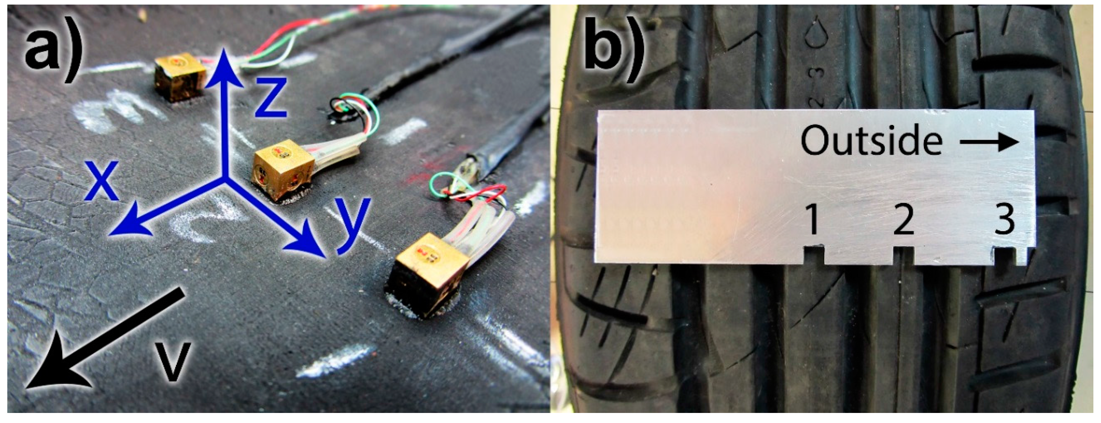
2.1. Accelerometers

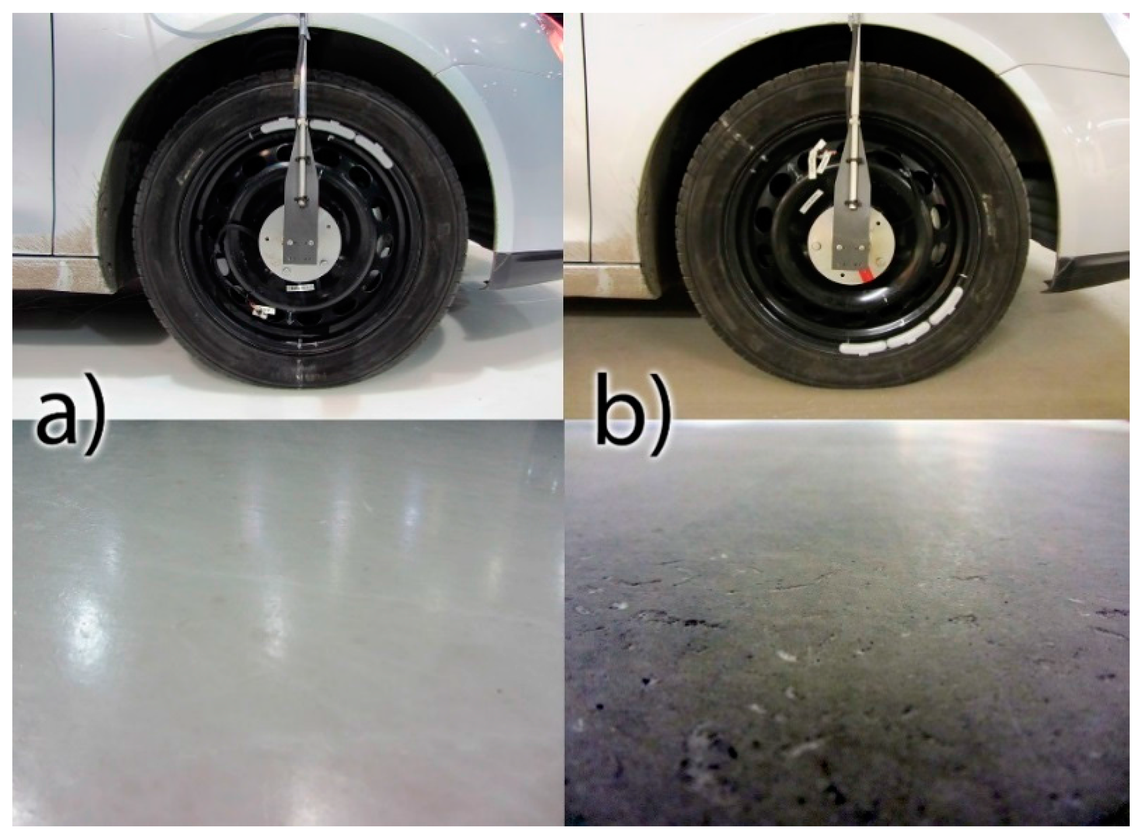
2.2. Measurements

3. Results and Discussion
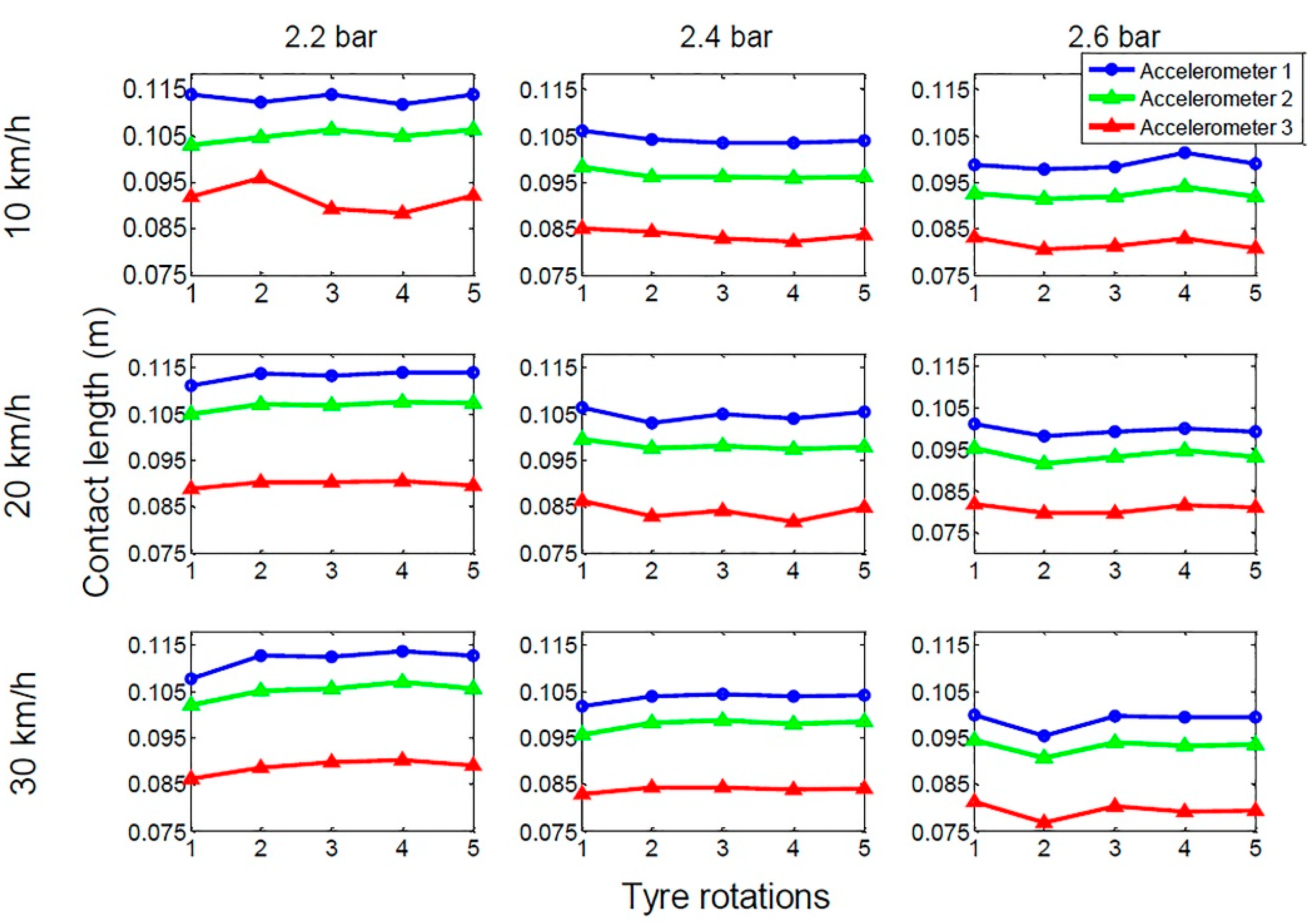
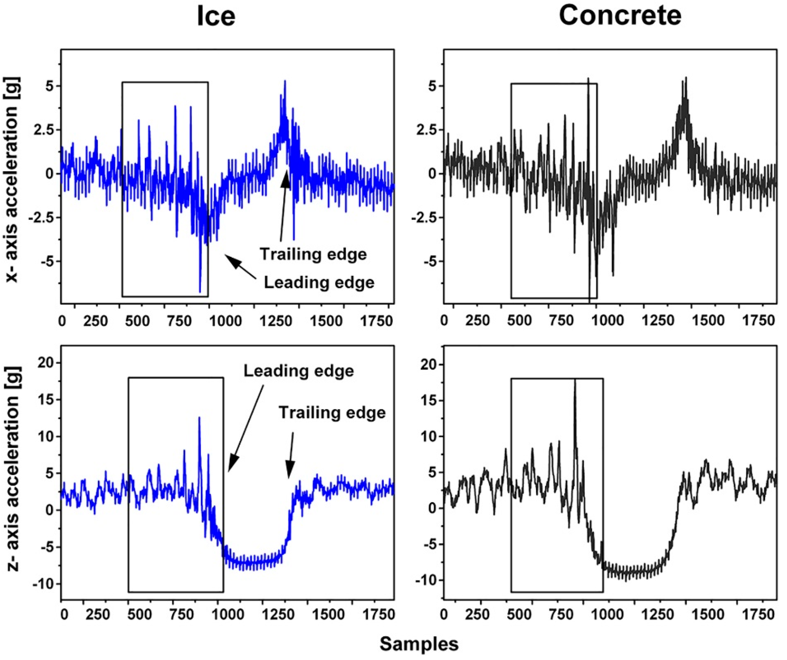
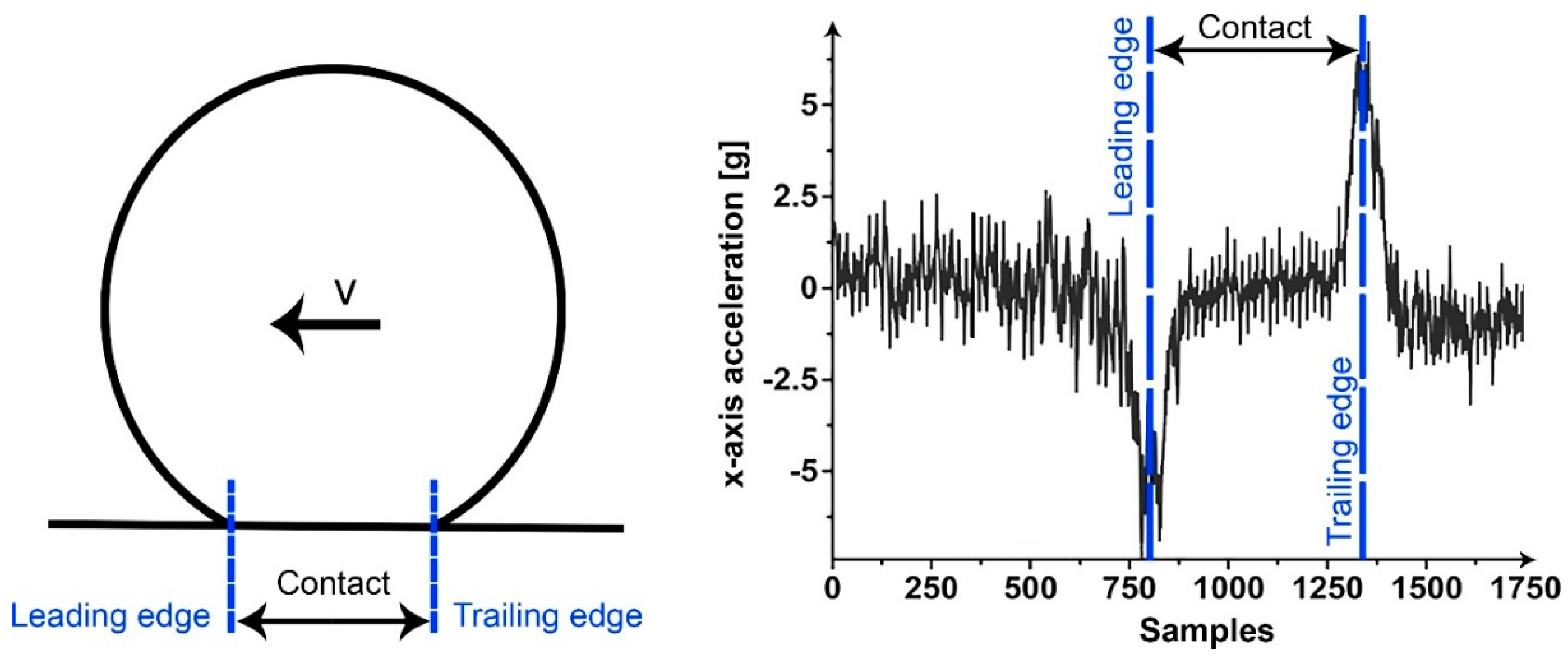
3.1. Contact Lengths

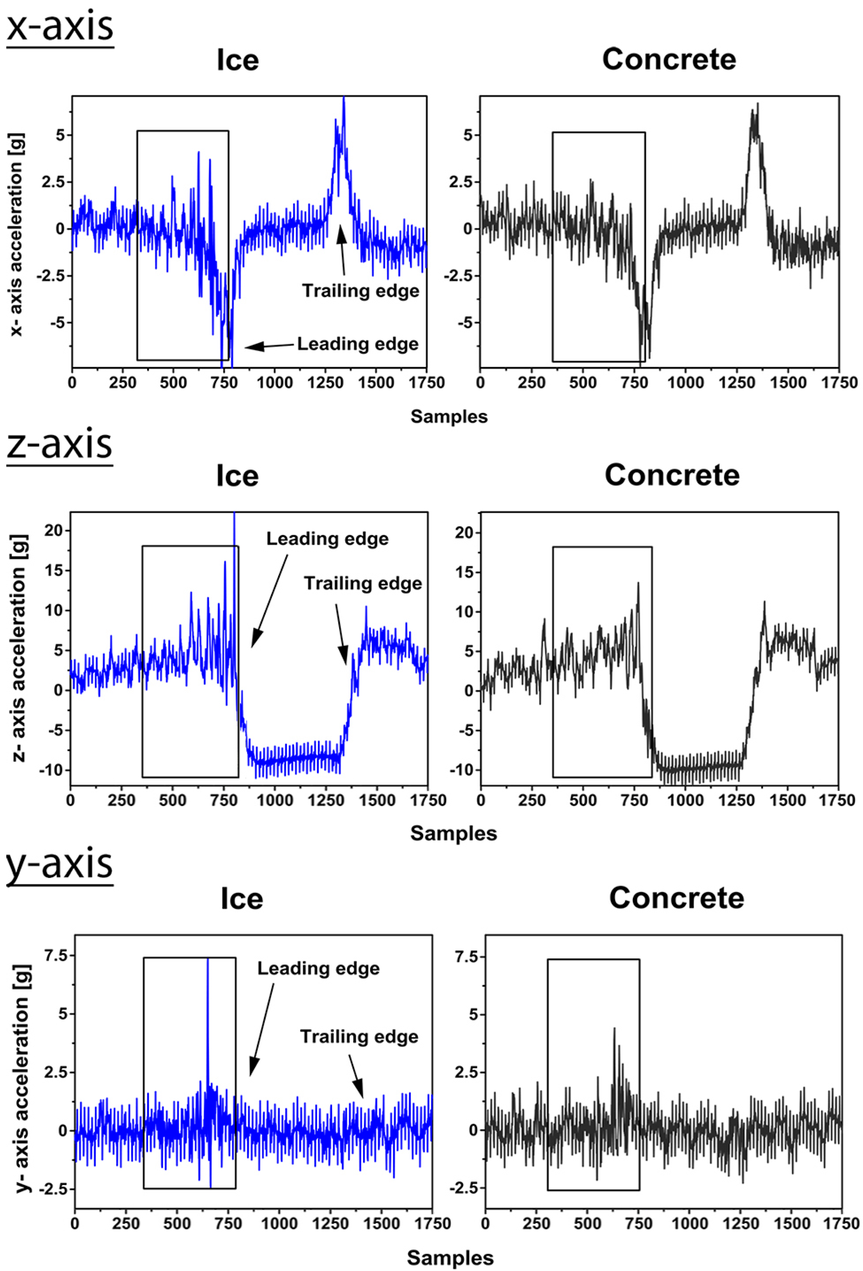
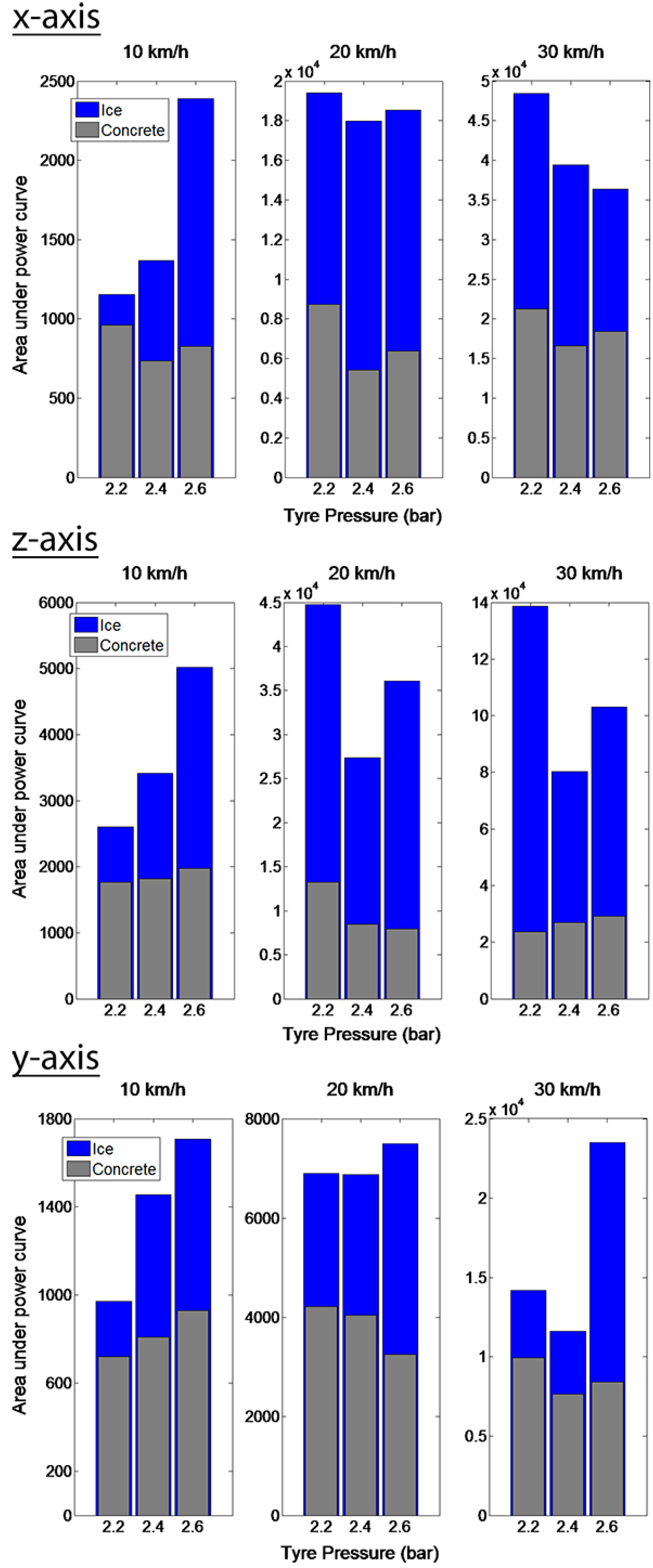
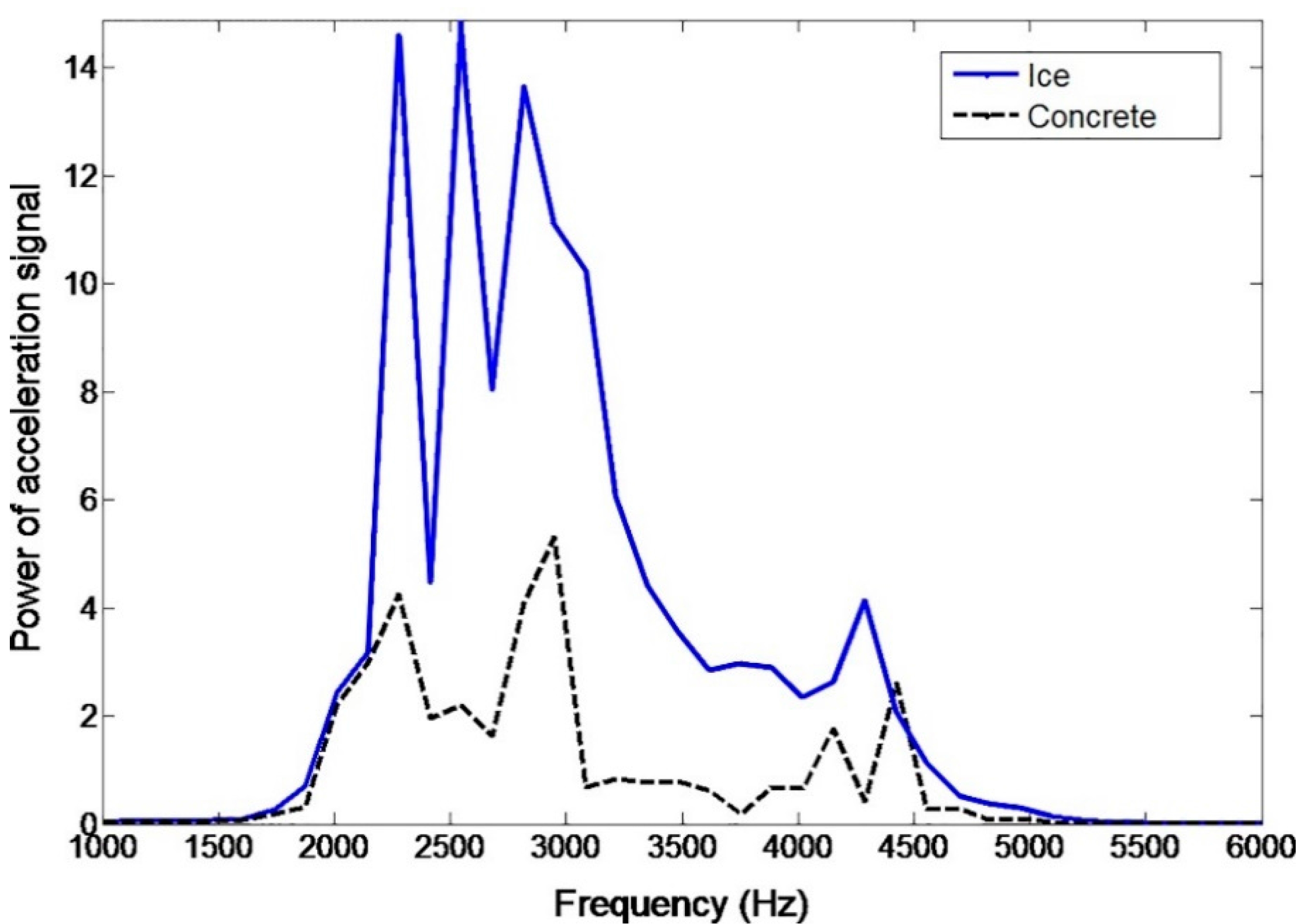
3.2. Friction Potential Indicators


4. Conclusions
Author Contributions
Conflicts of Interest
References
- Erke, A. Effects of Electronic Stability Control (ESC) on Accidents: A Review of Empirical Evidence. Accid. Anal. Prev. 2008, 40, 167–173. [Google Scholar] [CrossRef] [PubMed]
- Gobbi, M.; Mastinu, G. Wheels with Integrated Sensors for Measuring Tyre Forces and Moment. In Proceedings of the 7th International Symposium on Advanced Vehicle Control, Arnhem, The Netherlands, 23–27 August 2004.
- Pasterkamp, W.R.; Pacejka, H.B. The Tyre as Sensor to Estimate Friction. Veh. Syst. Dyn. 1997, 27, 409–422. [Google Scholar] [CrossRef]
- Van Leeuwen, B.; Pepe, F. SKF Load Sensing HBU. In Proceedings of the 4th International Conference on Advanced Chassis Control Systems, Orbassano, Italy, 2–3 October 2008.
- Becherer, T. The Sidewall Torsion Sensor System. In Proceedings of the 2. Darmstädter Reifenkolloquium, Darmstadt, Germany; 1998. Available online: https://getinfo.de/en/search/id/BLCP%3ACN026634165/ (accessed on 5 August 2015). (In German)[Google Scholar]
- Breuer, B.; Eichhorn, U.; Roth, J. Measurement of Tyre/Road-Friction Ahead of the Car and Inside the Tyre. In Proceedings of the International Symposium on Advanced Vehicle Control, Yokohama, Japan, 14–17 September 1992.
- Pohl, A.; Steindl, R.; Reindl, L. The “Intelligent Tire” Utilizing Passive SAW Sensors Measurement of Tire Friction. IEEE Trans. Instrum. Meas. 1999, 48, 1041–1046. [Google Scholar] [CrossRef]
- Morinaga, H.; Wakao, Y.; Hanatsuka, Y.; Kobayakawa, A. The Possibility of Intelligent Tire (Technology of Contact Area Information Sensing. In Proceedings of 31st FISITA World Automotive Congress, Yokohama, Japan, 22–27 October 2006.
- Braghin, F.; Brusarosco, M.; Cheli, F.; Cigada, A.; Manzoni, S.; Mancosu, F. Measurement of Contact Forces and Patch Features by Means of Accelerometers Fixed Inside the Tire to Improve Future Car Active Control. Veh. Syst. Dyn. 2006, 44, 3–13. [Google Scholar] [CrossRef]
- Matilainen, M.; Tuononen, A. Intelligent Tire to Measure Contact Length in Dry Asphalt and Wet Concrete Conditions. In Proceedings of the 11th International Symposium on Advanced Vehicle Control, Seoul, Korea, 9–12 September 2012.
- Niskanen, A.; Tuononen, A. Three 3-Axial Accelerometers Fixed Inside the Tyre for Studying Contact Patch Deformations in Wet Conditions. Veh. Syst. Dyn. 2014, 52, 1–14. [Google Scholar] [CrossRef]
- Matilainen, M.; Tuononen, A. Tyre Contact Length on Dry and Wet Road Surfaces Measured by Three-Axial Accelerometer. Mech. Syst. Signal Process. 2015, 52–53, 548–558. [Google Scholar] [CrossRef]
- Morinaga, H.; Hanatsuka, Y.; Wakao, Y. Sensing Technology Tire System for Road Surface Condition Judgment. In Proceedings of the FISITA 2010 World Automotive Congress, Budapest, Hungary, 30 May–4 June 2010.
- Morinaga, H. CAIS Technology for Detailed Classification of Road Surface Condition. In Proceedings of the Tire Technology Expo, Cologne, Germany, 5–7 February 2013.
- Singh, K.B.; Taheri, S. Piezoelectric Vibration-Based Energy Harvesters for Next-Generation Intelligent Tires. Tire Sci. Technol. 2013, 41, 262–293. [Google Scholar]
- Hong, S.; Erdogan, G.; Hedrick, K.; Borrelli, F. Tyre-Road Friction Coefficient Estimation Based on Tyre Sensors and Lateral Tyre Deflection: Modelling, Simulations and Experiments. Veh. Syst. Dyn. 2013, 51, 627–647. [Google Scholar] [CrossRef]
- Savaresi, S.M.; Tanelli, M.; Langthaler, P.; del Re, L. New Regressors for the Direct Identification of Tire Deformation in Road Vehicles via “In-Tire” Accelerometers. IEEE Trans. Control Syst. Technol. 2008, 16, 769–780. [Google Scholar] [CrossRef]
- Krier, D.; Zanardo, G.; Del Re, L. A PCA-Based Modeling Approach for Estimation of Road-Tire Forces by In-Tire Accelerometers. In Proceedings of the 19th World Congress of The International Federation of Automatic Control, Cape Town, South Africa, 24–29 August 2014.
- Erdogan, G.; Alexander, L.; Rajamani, R. Estimation of Tire-Road Friction Coefficient Using a Novel Wireless Piezoelectric Tire Sensor. IEEE Sens. J. 2011, 11, 267–279. [Google Scholar] [CrossRef]
- Rajamani, R.; Phanomchoeng, G.; Piyabongkarn, D.; Lew, J.Y. Algorithms for Real-Time Estimation of Individual Wheel Tire-Road Friction Coefficients. IEEE/ASME Trans. Mechatron. 2012, 17, 1183–1195. [Google Scholar] [CrossRef]
- Kim, C.S.; Hahn, J.O.; Hong, K.S.; Yoo, W.S. Estimation of Tire-Road Friction Based on On-Board 6-DoF Acceleration Measurement. IEEE Trans. Veh. Technol. 2014, 99, 1–9. [Google Scholar] [CrossRef]
- Endevco 35A Datasheet. Available online: https://www.endevco.com/product/prodpdf/35A.pdf (accessed on 13 May 2015).
- Sandberg, U.; Ejsmont, J.A. Tyre/Road Noise Reference Book; Informex: Kisa, Sweden, 2002. [Google Scholar]
- Brusarosco, M.; Cigada, A.; Manzoni, S. Measurement and Analysis of Tyre and Tread Block Dynamics Due to Contact Phenomena. Veh. Syst. Dyn. 2011, 49, 855–869. [Google Scholar] [CrossRef]
© 2015 by the authors; licensee MDPI, Basel, Switzerland. This article is an open access article distributed under the terms and conditions of the Creative Commons Attribution license (http://creativecommons.org/licenses/by/4.0/).
Share and Cite
Niskanen, A.; Tuononen, A.J. Three Three-Axis IEPE Accelerometers on the Inner Liner of a Tire for Finding the Tire-Road Friction Potential Indicators. Sensors 2015, 15, 19251-19263. https://doi.org/10.3390/s150819251
Niskanen A, Tuononen AJ. Three Three-Axis IEPE Accelerometers on the Inner Liner of a Tire for Finding the Tire-Road Friction Potential Indicators. Sensors. 2015; 15(8):19251-19263. https://doi.org/10.3390/s150819251
Chicago/Turabian StyleNiskanen, Arto, and Ari J. Tuononen. 2015. "Three Three-Axis IEPE Accelerometers on the Inner Liner of a Tire for Finding the Tire-Road Friction Potential Indicators" Sensors 15, no. 8: 19251-19263. https://doi.org/10.3390/s150819251