Magnetic Sensor for Building Structural Vibrations


Abstract
: This paper shows a new displacement-to-frequency transducer based on the variation of a coil inductance when a magnetic core is partially or completely inserted inside. This transducer is based on a Colpitts oscillator due its low manufacturing price, behavior and immunity to noise. A tank circuit with a configuration in parallel was used because it can be employed at lower frequencies and it enables it to make a direct analysis. The sensor has a dynamic range equal to the length of the coil. The cores can exchange sensors (coils with its ferromagnetic core) using the same electronic measuring system. In this way, with only an electronic circuit, the core sensor determines the measurement range. The obtained resolution is higher than 1/100,000, and the sensor also allows the measurement and knowing in real time the effect of vibration, thermal expansion, referred overload movements, etc.., that can occur in the structural elements of a building.1. Introduction
To ensure the reliable evaluation of a building structure's condition and to know its stability conditions displacement measurements are required. There are many devices to measure these displacements: capacitive, accelerometer, optical and inductive sensors and real-time kinematic global positioning systems [1–2].
Inductive Linear Variable Differential Transformer (LVDT) sensors are some of the most used sensors in displacement measurements due to the advantages offered by their electrical insulation between the sensor and measurement electronics; their hardness that allows them to be used in unclean or unfavorable environments and their reliability that allows them to make measurements with a higher accuracy than 1/10,000 [3–7].
But, they some disadvantages such as their dimensions (the range a LVDT measures is always less than ½ of the total length of the windings) and the complexity of the associated measurement electronics (voltage and phase) that need to be detected in order to discriminate the direction and magnitude of the displacement and the fact a good stabilization of the working frequency is required. As they are mutual induction amplitude systems, they depend on the frequency of the driving signal [8–11].
In this work a new displacement-to-frequency transducer based on the variation of the self-inductance of a coil is shown, when the magnetic core (sensor nucleus) is partially or completely inserted in a single coil. This transducer is based in a Colpitts oscillator circuit that has low manufacturing prices, and a great immunity to noise. A tank circuit with a parallel configuration was used because it can be used at lower frequencies and allows making a direct analysis.
The sensor was designed using four coils of different sizes and also with a different number of turns but with the same self-inductance (L = 39.5 μH). In this way, the electronic circuit can be the same for different sensor cores. Thus, as the sensor has a dynamic range equal to the length of the inductance, the core sensor (coil with its ferromagnetic core) can be exchanged with the same electronic measuring system. In this way, the range of measurement is only determined by the core sensor selected, using the same electronics for all sensor cores. The resolution obtained is higher than 1/100,000.
2. The Transducer
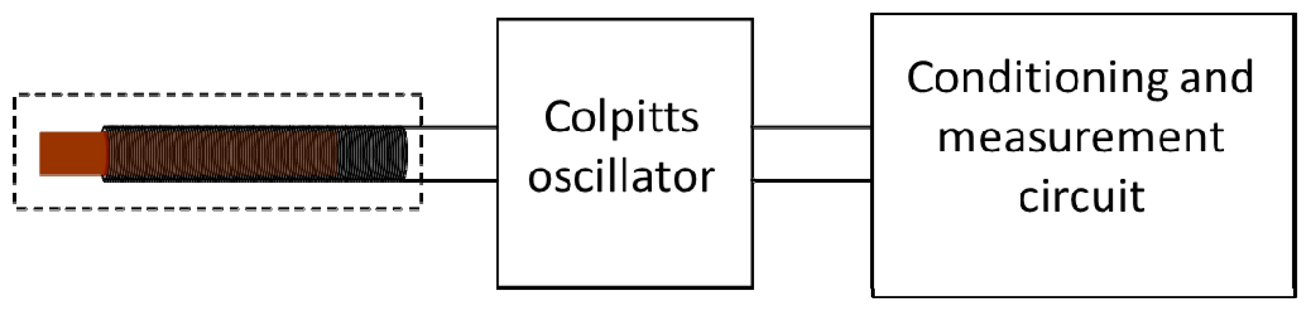
Figure 1 shows the block diagram of the magnetic transducer. The sensor head is connected with the circuit oscillator whose frequency of oscillation depends on the self-induction of the sensor head made of a coil and a sliding ferromagnetic core. The next is the electronic signal conditioning and measurement block. Essentially it takes the signal of the oscillator, fits the amplitude and measures the frequency of the same one correlating it with the corresponding distance.
2.1. The Electronic Circuit
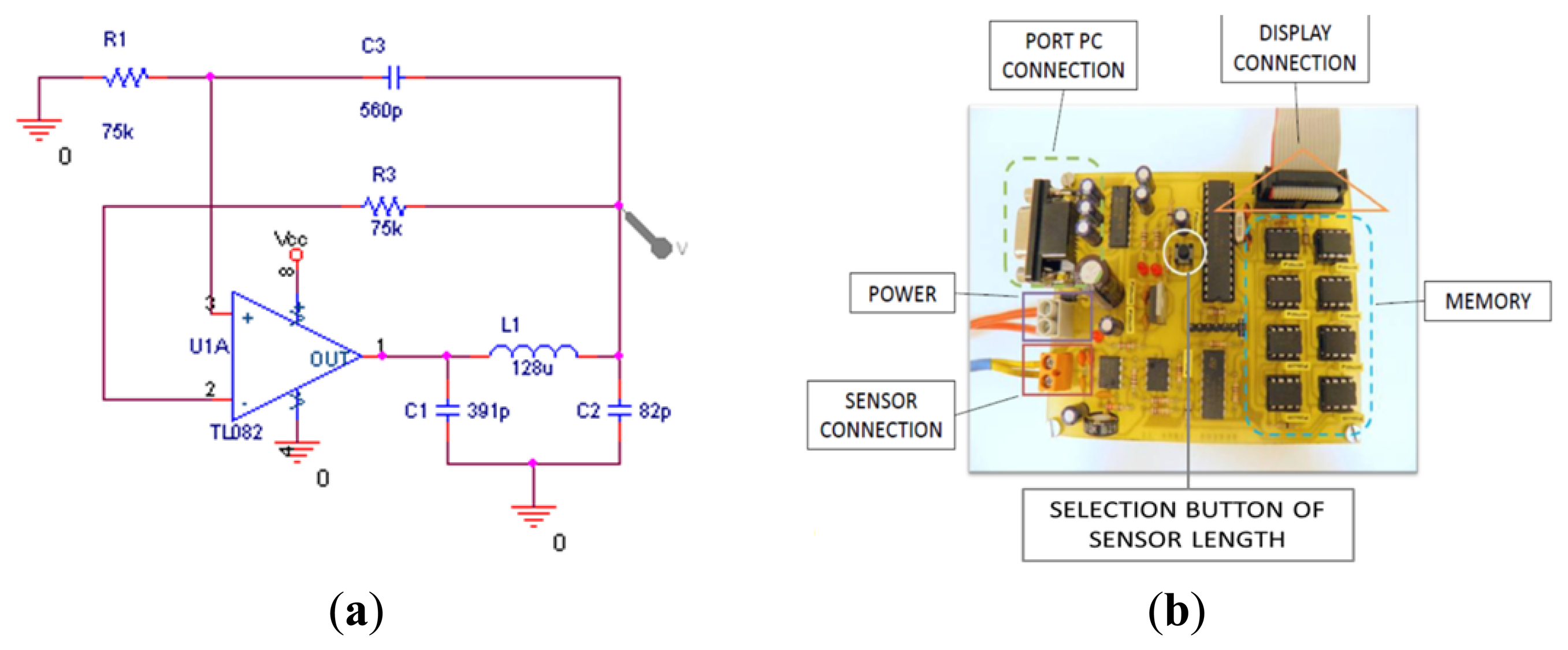
The general structure of a standard Colpitts oscillator with an operational amplifier as an active element is shown in Figure 2, where C1 and C2 are capacitors and L1 the coil. The negative feedback circuit will oscillate if the transfer function loop reaches a unit amplitude (0 dB) when the phase shift is −180°.
2.2. Coil Design and Construction
It was decided that coils of different longitude would be developed, but with the same self-inductance. In this way, the dynamic range of the transducer (coil length) can be chosen without the need to make adjustments (or changes) in the electronic circuitry. The self-induction of a coil without a ferromagnetic core can be obtained as:
Taking into account the section of wire Φ (for the same winding base), the total length is:
The cross sectional area of the coil (taking into account that it is only one layer of coil winding) must change with the wire section Φ:
To ensure that two different coils (with different wire sections and different total length) have the same self-induction, it is necessary that the relation between the numbers of winding be:
Four different coils have been made. Table 1 shows the coils that have been developed: their length, theoretical number and the real number of turns.
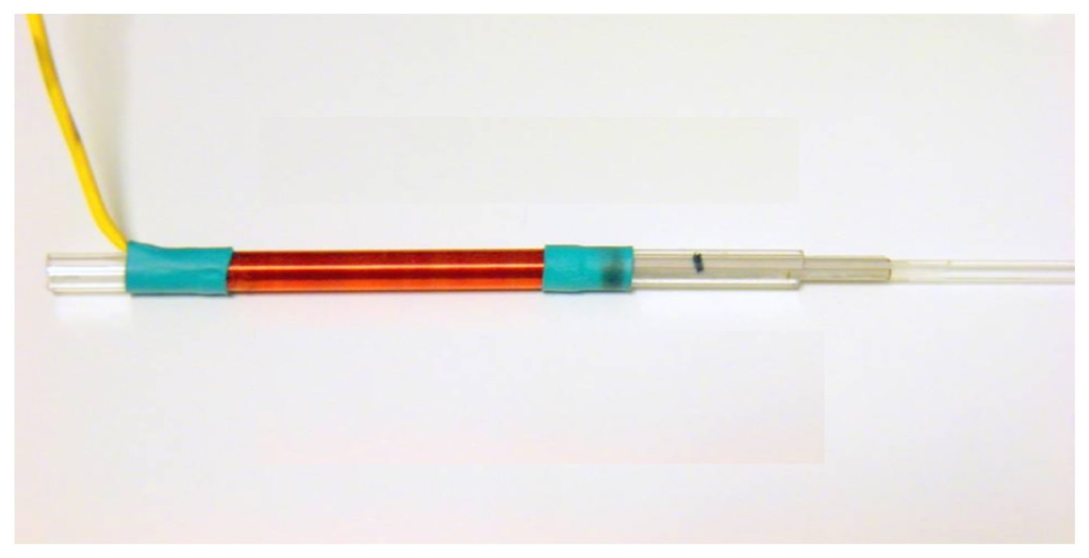
Figure 3 shows the built coils. All coils are wound over the same tubular base. There is only one layer of wound coil; different enameled copper wire has been used and different coil lengths have been obtained, but all coils have the same self-induction: 39.5 μH.
3. Properties of the Transducer
Two magnetic materials with different properties have been used as sliding ferromagnetic cores (Figure 4) to see how the transducer behaves with each of them. In one case a 3 mm diameter mild steel bar was used and in another case six sheets of an electrically isolated amorphous magnetic material (METGLAS 2705M, Metglas®, Inc., Conway, SC, USA) was used.
To obtain the range of the transducer, with both materials used for the nucleus, the frequencies with only the coil (without magnetic material inside) and when all magnetic nuclei are inserted inside them have been measured. The procedure was repeated for each of the four built coils. In Table 2 the frequency range (maximum frequency range of sensor response) and the frequency obtained for the four coils are shown.
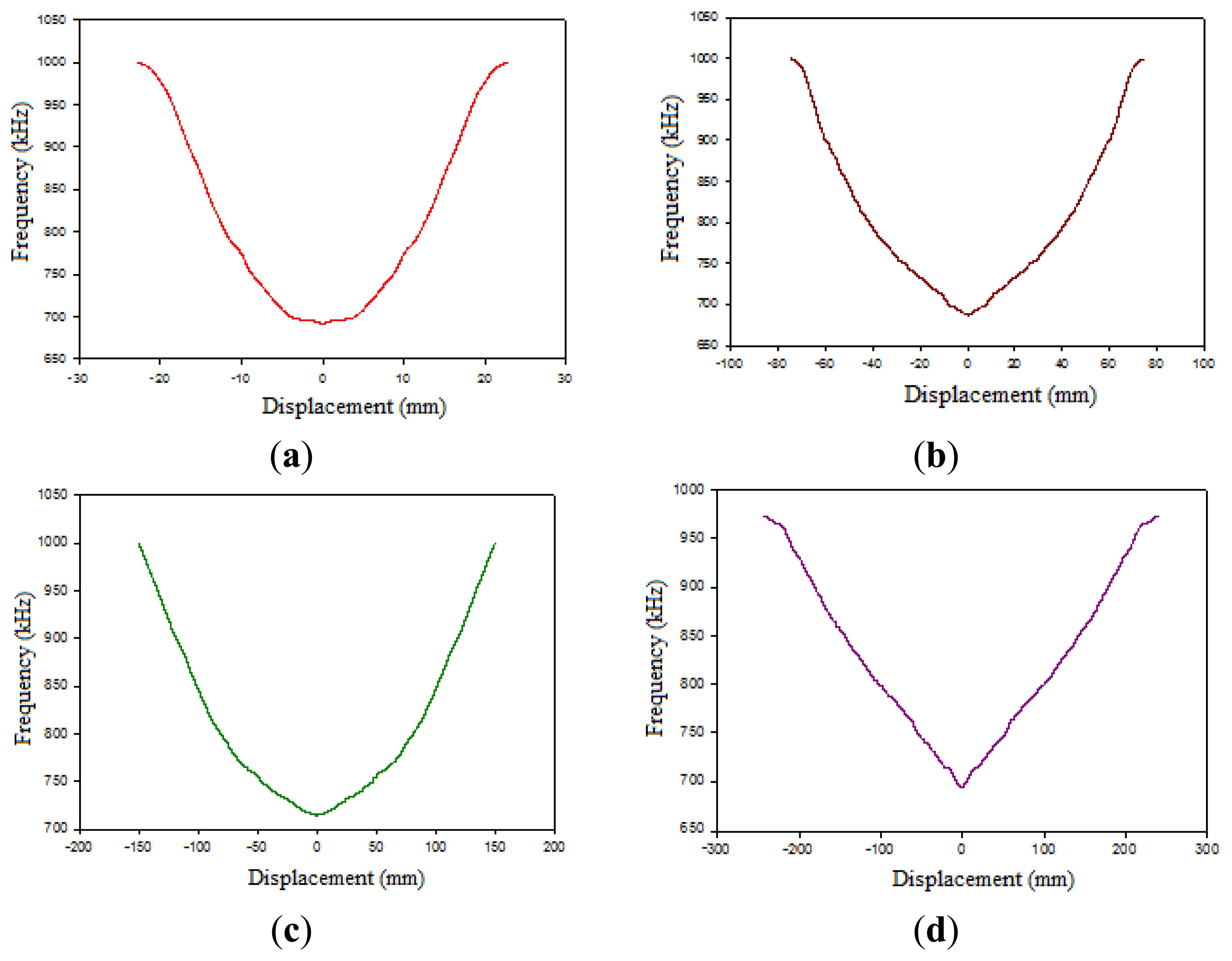
3.1. Calibration
Calibrations for the transducer have been made with all the coils and mild steel and METGLASS 2705M materials as magnetic nucleus. Figure 5 shows the results obtained for one tested coil with a mild steel bar or METGLASS 2705M as sensor core.
3.2. Resolution and Threshold
The threshold at 0 mm has been obtained and this parameter can be expressed as signal/noise ratio:
In Table 3 the transducer thresholds for the four developed coils are shown.
3.3. Thermal Stability
Studies of the thermal stability of the transducer have been performed. To do this, a heater has been used and the frequency of response for different displacements has been measured by varying the temperature (the displacement was maintained constant for each temperature variation). The thermal study has been done with a muffle furnace with a temperature control that provides a precision of ±1 °C for three temperatures (20 °C, 40 °C and 60 °C). It has been observed that the maximum frequency variation was 24 Hz—equivalent to 21 μm (below the sensor accuracy 33.5 Hz—equivalent to 28 μm).
In this way, the frequency response variation with temperature obtained was almost negligible.
3.4. Results
The sensor with 280 mm length coil was placed at 1.05 m from the column (Figure 6) to measure the vibration produced by the passage of cars in an underground parking garage.
In Figure 7 the 280 mm length coil response can be seen. The data has been updated every 2 s. The areas marked with a box correspond to the parking garage. The marks in orange correspond to cars leaving the low floor parking garage and the marks in blue, to cars going out of upper floor parking garage. Within these areas the highest peak coincides with the closure of the parking door. Also, the areas marked with an arrow indicate traffic on the road outside just above the underground parking garage. The other relevant peaks, between 618 and 618.1 kHz for example, probably indicate the exits or entries from the street parking lot.
4. Conclusions
A displacement-to-frequency transducer has been built, whose dynamic range can be changed simply by exchanging a sensor head for another, without making any adjustments or changes to the associated electronic devices. This transducer is based on a single coil (LVDTs need three coils). The dynamic range is nearly equal to the length of the coil (LVDTs have a dynamic range of less than ½ of the total length of windings). The device shows a high thermal stability. As it is a magnetic device, there is electrical insulation between the sensor head and the associated electronics. Furthermore, the device is not very expensive. All these features make this transducer suitable for all types of industrial applications, including those in hazardous locations or large contaminated areas.
Acknowledgments
This work was partially supported by the Polytechnic University of Madrid and by the Spanish MICINN under project DPI2011-24113.
Conflicts of Interest
The authors declare no conflict of interest.
References
- Hwang, J.; Yun, H.; Park, S.K.; Lee, D.; Hong, S. Optimal methods of RTK-GPS/accelerometer integration to monitor the displacement of structures. Sensors 2012, 12, 1014–1034. [Google Scholar]
- Gao, J.; Müller, W.F.O.; Greiner, F.; Eicher, D.; Weiland, T.; Schlaak, H.F. Combined simulation of a micro permanent magnetic linear contactless displacement sensor. Sensors 2010, 10, 8424–8436. [Google Scholar]
- Ripka, P. Magnetic Sensors and Magnetometers; Artech House: Boston, MA, USA, 2001. [Google Scholar]
- Hernando, A.; Vázquez, M.; Barandiarán, J.M. Metallic glasses and sensing applications. J. Phys. E Sci. Instrum. 1988, 21, 1129–1139. [Google Scholar]
- Wu, S.T.; Mo, S.C.; Wu, B.S. An LVDT-based self-actuating displacement transducer. Sens. Actuators A Phys. 2008, 141, 558–564. [Google Scholar]
- Chiriac, C.; Chiriac, H. Magnetic field and displacement sensor based on linear transformer with amorphous wire core. Sens. Actuators A Phys. 2003, 106, 172–173. [Google Scholar]
- Zikmund, A.; Ripka, P. A magnetic distance sensor with high precision. Sens. Actuators A Phys. 2012, 186, 137–142. [Google Scholar]
- Ali, R.; Mahapatra, D.R.; Gopalakrishnan, S. An analytical model of constrained piezoelectric thin film sensors. Sens. Actuators A Phys. 2004, 116, 424–437. [Google Scholar]
- Niko la Jeranče, N.; Vasiljević, D.; Samardžić, N.; Stojanović, G. A compact inductive position sensor made by inkjet printing technology on a flexible substrate. Sensors 2012, 12, 1288–1298. [Google Scholar]
- Misron, N.; Ying, L.Q.; Firdaus, R.N.; Abdullah, N.; Mailah, N.F.; Wakiwaka, H. Effect of inductive coil shape on sensing performance of linear displacement sensor using thin inductive coil and pattern guide. Sensors 2011, 11, 10522–10533. [Google Scholar]
- Norhisam, M.; Norrimah, A.; Wagiran, R.; Sidek, R.M.; Mariun, N.; Wakiwaka, H. Consideration of theoretical equation for output voltage of linear displacement sensor using meander coil and pattern guide. Sens. Actuators A Phys. 2008, 147, 470–473. [Google Scholar]


| Wire Diameter (mm) | Length (mm) | Theoretical Winding Number | Actual Winding Number |
|---|---|---|---|
| 0.400 | 280 | 700 | 690 |
| 0.315 | 178 | 566 | 555 |
| 0.224 | 92.7 | 414 | 405 |
| 0.100 | 19.3 | 193 | 181 |
| Coil Length (mm) | Magnetic Material | Range (mm) | Frequency Range (kHz) | Precision (Hz/μm) |
|---|---|---|---|---|
| 19.3 | Steel | 19 | 102 | 5 |
| Metglas | 19 | 313 | 16 | |
| 92.7 | Steel | 93 | 96 | 1 |
| Metglas | 93 | 308 | 3 | |
| 178 | Steel | 178 | 100 | 0.5 |
| Metglas | 178 | 305 | 1.7 | |
| 280 | Steel | 280 | 95 | 0.3 |
| Metglas | 280 | 335 | 1 |
| Coil Length (mm) | Mild Steel Bar (dB) | METGLASS 2705M (dB) |
|---|---|---|
| 19.3 | 2.07 | 3.21 |
| 92.7 | 1.76 | 3.25 |
| 178 | 0.98 | 2.92 |
| 280 | 0.91 | 3.19 |
© 2014 by the authors; licensee MDPI, Basel, Switzerland. This article is an open access article distributed under the terms and conditions of the Creative Commons Attribution license ( http://creativecommons.org/licenses/by/3.0/).
Share and Cite
García, A.; Morón, C.; Tremps, E. Magnetic Sensor for Building Structural Vibrations. Sensors 2014, 14, 2468-2475. https://doi.org/10.3390/s140202468
García A, Morón C, Tremps E. Magnetic Sensor for Building Structural Vibrations. Sensors. 2014; 14(2):2468-2475. https://doi.org/10.3390/s140202468
Chicago/Turabian StyleGarcía, Alfonso, Carlos Morón, and Enrique Tremps. 2014. "Magnetic Sensor for Building Structural Vibrations" Sensors 14, no. 2: 2468-2475. https://doi.org/10.3390/s140202468
APA StyleGarcía, A., Morón, C., & Tremps, E. (2014). Magnetic Sensor for Building Structural Vibrations. Sensors, 14(2), 2468-2475. https://doi.org/10.3390/s140202468