<?xml version="1.0" encoding="UTF-8"?>
<!DOCTYPE article PUBLIC "-//NLM//DTD Journal Publishing DTD v2.3 20070202//EN" "journalpublishing.dtd">
<article xmlns:mml="http://www.w3.org/1998/Math/MathML" xmlns:xlink="http://www.w3.org/1999/xlink" xml:lang="en" article-type="research-article">
<front>
<journal-meta>
<journal-id journal-id-type="nlm-ta">Sensors</journal-id>
<journal-title>Sensors</journal-title>
<issn pub-type="epub">1424-8220</issn>
<publisher>
<publisher-name>Molecular Diversity Preservation International (MDPI)</publisher-name></publisher></journal-meta>
<article-meta>
<article-id pub-id-type="doi">10.3390/s120911559</article-id>
<article-id pub-id-type="publisher-id">sensors-12-11559</article-id>
<article-categories>
<subj-group>
<subject>Article</subject></subj-group></article-categories>
<title-group>
<article-title>A Method for Evaluating the Electro-Mechanical Characteristics of Piezoelectric Actuators during Motion</article-title></title-group>
<contrib-group>
<contrib contrib-type="author">
<name><surname>Jin</surname><given-names>Tao</given-names></name><xref ref-type="aff" rid="af1-sensors-12-11559"><sup>1</sup></xref><xref ref-type="corresp" rid="c1-sensors-12-11559"><sup>*</sup></xref></contrib>
<contrib contrib-type="author">
<name><surname>Takita</surname><given-names>Akihiro</given-names></name><xref ref-type="aff" rid="af1-sensors-12-11559"><sup>1</sup></xref></contrib>
<contrib contrib-type="author">
<name><surname>Djamal</surname><given-names>Mitra</given-names></name><xref ref-type="aff" rid="af2-sensors-12-11559"><sup>2</sup></xref></contrib>
<contrib contrib-type="author">
<name><surname>Hou</surname><given-names>Wenmei</given-names></name><xref ref-type="aff" rid="af3-sensors-12-11559"><sup>3</sup></xref></contrib>
<contrib contrib-type="author">
<name><surname>Jia</surname><given-names>Hongzhi</given-names></name><xref ref-type="aff" rid="af3-sensors-12-11559"><sup>3</sup></xref></contrib>
<contrib contrib-type="author">
<name><surname>Fujii</surname><given-names>Yusaku</given-names></name><xref ref-type="aff" rid="af1-sensors-12-11559"><sup>1</sup></xref></contrib></contrib-group>
<aff id="af1-sensors-12-11559">
<label>1</label> Department of Electronic Engineering, Faculty of Engineering, Gunma University, 1-5-1 Tenjin-cho, Kiryu, Gunma 376-8515, Japan; E-Mails: <email>takita@el.gunma-u.ac.jp</email> (A.T.); <email>fujii@el.gunma-u.ac.jp</email> (Y.F.)</aff>
<aff id="af2-sensors-12-11559">
<label>2</label> Department of Physics, Faculty of Mathematics and Natural Sciences, Institut Teknologi Bandung, Jalan Ganesa 10, Bandung 40132, Indonesia; E-Mail: <email>mitra@fi.itb.ac.id</email></aff>
<aff id="af3-sensors-12-11559">
<label>3</label> Shanghai Key Laboratory of Modern Optical System, School of Optical-Electrical and Computer Engineering, University of Shanghai for Science and Technology, Shanghai 200093, China; E-Mail: <email>houwenmei@vip.citiz.net</email> (W.M.H.); <email>jiahongzhi0715@sina.com</email> (H.Z.J.)</aff>
<author-notes>
<corresp id="c1-sensors-12-11559">
<label>*</label>Author to whom correspondence should be addressed; E-Mail: <email>t10802472@gunma-u.ac.jp</email>; Tel./Fax: +81-277-301-748.</corresp></author-notes>
<pub-date pub-type="collection">
<year>2012</year></pub-date>
<pub-date pub-type="epub">
<day>24</day>
<month>08</month>
<year>2012</year></pub-date>
<volume>12</volume>
<issue>9</issue>
<fpage>11559</fpage>
<lpage>11570</lpage>
<history>
<date date-type="received">
<day>15</day>
<month>06</month>
<year>2012</year></date>
<date date-type="rev-recd">
<day>08</day>
<month>08</month>
<year>2012</year></date>
<date date-type="accepted">
<day>14</day>
<month>08</month>
<year>2012</year></date></history>
<permissions>
<copyright-statement>© 2012 by the authors; licensee MDPI, Basel, Switzerland.</copyright-statement>
<copyright-year>2012</copyright-year>
<license>
<p>This article is an open access article distributed under the terms and conditions of the Creative Commons Attribution license (http://creativecommons.org/licenses/by/3.0/).</p></license></permissions>
<abstract>
<p>The electro-mechanical characteristics of piezoelectric actuators which have being driven are evaluated in this paper. The force generated by actuators is measured as an inertial force of a corner cub prism which is attached to the actuators. The Doppler frequency shift of a laser beam, due to the motion of actuator, is accurately measured by a heterodyne interferometer. Subsequently, the mechanical quantities, such as velocity, acceleration, force, power and displacement, are calculated from the Doppler frequency shift. With the measurement results of current and voltage of the actuator, the relationships between electrical and mechanical characteristics are evaluated.</p></abstract>
<kwd-group>
<kwd>piezo actuator</kwd>
<kwd>Doppler frequency shift</kwd>
<kwd>dynamic measurement</kwd>
<kwd>interferometer</kwd></kwd-group></article-meta></front>
<body>
<sec sec-type="intro">
<label>1.</label>
<title>Introduction</title>
<p>Piezo-electric (PZT) actuator, with high stiffness, compact size and high resolution, has been applied in many areas related to precision position and force control and/or measure [<xref ref-type="bibr" rid="b1-sensors-12-11559">1</xref>–<xref ref-type="bibr" rid="b3-sensors-12-11559">3</xref>]. The static output characteristics of conventional PZT actuator are typically evaluated by standard static methods, e.g., using static weights under static conditions. The dynamic outputs of PZT actuator including force and displacement are usually measured by using force and displacement transducer, respectively. However, so far, no standard dynamic calibration method for force transducer has been proposed. In other words, the uncertainly of transducer influences the accuracy of dynamic measuring results.</p>
<p>Instead of force transducer, a spring-mass-damper (SMD) is used for dynamic analysis characteristics of actuators [<xref ref-type="bibr" rid="b4-sensors-12-11559">4</xref>,<xref ref-type="bibr" rid="b5-sensors-12-11559">5</xref>]. The dynamic force is measured as the impedance interactions between actuators and load structure, <italic>i.e.</italic>, SMD. In this method, the stiffness of spring and the coefficient of piezoelectric thin film stocked in actuator during motion direction are considered constant. However, compound components such as piezo-stack actuators can not be described sufficiently by piezoelectric coefficients, which vary with temperature, pressure, electric field, mechanical and electrical boundary conditions <italic>etc.</italic> [<xref ref-type="bibr" rid="b6-sensors-12-11559">6</xref>,<xref ref-type="bibr" rid="b7-sensors-12-11559">7</xref>]. A mass was loaded to PZT actuator by using a rotating arm via a high stiffness transmission rod [<xref ref-type="bibr" rid="b8-sensors-12-11559">8</xref>]. Several displacement transducers were used to measure the rotation of the arm in order to calculate the force generated or applied on PZT actuator. In this device, the accuracy of displacement measurement is sensitive to temperature. Some models for the dynamic analysis of the electro-mechanical characteristics of PZT actuator are proposed [<xref ref-type="bibr" rid="b9-sensors-12-11559">9</xref>,<xref ref-type="bibr" rid="b10-sensors-12-11559">10</xref>]. In those models, the design of mechanical parameters is based on testing actuator with dead weight, known structure or transducer <italic>etc.</italic> Several kinds of interferometer, such as signal frequency interferometer, laser Doppler interferometer and laser diode interferometer <italic>etc.</italic>, are introduced to accurately measure the displacement of actuators/piezoelectric thin film [<xref ref-type="bibr" rid="b11-sensors-12-11559">11</xref>,<xref ref-type="bibr" rid="b12-sensors-12-11559">12</xref>]. However, they failed to measure the dynamic force. Some studies, in which dynamic responses of force transducers against some typical dynamic forces, such as impact force [<xref ref-type="bibr" rid="b13-sensors-12-11559">13</xref>], step force [<xref ref-type="bibr" rid="b14-sensors-12-11559">14</xref>] and oscillation force [<xref ref-type="bibr" rid="b15-sensors-12-11559">15</xref>], are mentioned based on the Levitation Mass Method (LMM). In the LMM, the inertial force of a mass, which is levitated using an aerostatic linear bearing with sufficiently small friction [<xref ref-type="bibr" rid="b16-sensors-12-11559">16</xref>], is used. Acceleration of the mass is accurately measured by means of an optical interferometer [<xref ref-type="bibr" rid="b17-sensors-12-11559">17</xref>]. The LMM has been applied to dynamic calibration for force transducers and material testers [<xref ref-type="bibr" rid="b18-sensors-12-11559">18</xref>,<xref ref-type="bibr" rid="b19-sensors-12-11559">19</xref>].</p>
<p>This paper aims to measure and evaluate the electric-mechanical characteristics of piezoelectric actuators during dynamic condition. The method proposed in this study does not need any force transducer and the characteristics of host or preloading. Our method, the modified LMM, is different from the conventional Doppler velocimeter. First, in the LMM, the inertial force is measured as the definition of force, the product of mass and acceleration. Second, the beat frequencies of the laser lights are highly accurately calculated by the Zero-crossing Fitting Method (ZFM), which has proposed by us [<xref ref-type="bibr" rid="b17-sensors-12-11559">17</xref>]. All other quantities, e.g., velocity, acceleration, displacement and force, are calculated from the frequencies. In this paper, a corner-cube prism (CC) is attached to the tip of PZT actuators with high stiffness metal blocks. The force generated by the actuator is calculated as the inertial force of the total mass of CC and blocks. An optical interferometer is introduced to measure the Doppler frequency shift caused by the motion of PZT actuators. Velocity, acceleration, force, power and displacement of the actuators during motion are measured from the Doppler frequency. Force-displacement behaviors of the actuators under dynamic condition are characterized. The relationships of energy conversion between electrical and mechanical domains are also characterized based on the observed results.</p></sec>
<sec>
<label>2.</label>
<title>Experimental Setup</title>
<p>
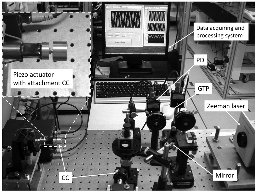
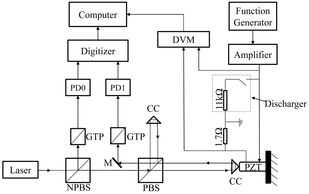
A schematic diagram of experimental setup and photographs of measurement system are shown in <xref ref-type="fig" rid="f1-sensors-12-11559">Figures 1</xref> and <xref ref-type="fig" rid="f2-sensors-12-11559">2</xref>, respectively. A CC is attached to a piezo-stack actuator with some metal blocks and the total mass of metal blocks including the CC is 9.07<italic>g</italic>. The actuator is driven by a sinusoid signal at a frequency of 100<italic>Hz</italic> which is generated by a function generator and amplified by a piezoelectric driver. The actuator is connected with a shunt resistor. The voltage of actuator and shunt resister are measured by a digital voltmeter (DVM), which is based on a data acquisition card (PCI-6221, manufactured by National Instruments Corp., USA). The current of actuator is calculated as the current of shunt resistor. A discharger is used for discharging the actuator.</p>
<p>A Zeeman-type two-frequency He-Ne laser is used as the light source of the optical interferometer. The interferometer has two photo-detectors: PD0 and PD1. The waveforms appearing at PD0 and PD1 are recorded using a digitizer (model: 5102; manufactured by National Instruments Corp., USA) with the sampling rate of 20 MS/s and the sampling length of 5 m, then the frequencies are accurately calculated from the waveform using ZFM, in which all the zero-crossing are used for estimating the frequency in each measurement period [<xref ref-type="bibr" rid="b17-sensors-12-11559">17</xref>].</p>
<p>The frequency difference, <italic>f<sub>rest</sub></italic> between the two orthogonal polarization states light emitted from the laser is monitored using a Glan–Thompson prism (GTP) and PD0. The total force, <italic>F</italic>, action on the attached mass is calculated as the product of its mass <italic>M</italic> and acceleration <italic>a</italic> as follows:
<disp-formula id="FD1">
<mml:math id="mm1" display="block">
<mml:semantics id="sm1">
<mml:mrow>
<mml:mi>F</mml:mi>
<mml:mo>=</mml:mo>
<mml:mi>M</mml:mi>
<mml:mi>a</mml:mi></mml:mrow></mml:semantics></mml:math></disp-formula></p>
<p>In the measurement, <italic>F</italic> is considered to be generated by the actuator and applied to the mass at the contact surface between the actuator and the mass. The acceleration is calculated from the velocity of mass which is measured as the Doppler shift frequency, <italic>f<sub>Doppler</sub></italic>.</p>
<p>
<disp-formula id="FD2">
<mml:math id="mm2" display="block">
<mml:semantics id="sm2">
<mml:mrow>
<mml:mtable columnalign="left">
<mml:mtr>
<mml:mtd>
<mml:mrow>
<mml:mi>v</mml:mi>
<mml:mo>=</mml:mo>
<mml:msub>
<mml:mi>λ</mml:mi>
<mml:mrow>
<mml:mtext mathvariant="italic">air</mml:mtext></mml:mrow></mml:msub>
<mml:msub>
<mml:mi>f</mml:mi>
<mml:mrow>
<mml:mtext mathvariant="italic">Doppler</mml:mtext></mml:mrow></mml:msub>
<mml:mo stretchy="true">/</mml:mo>
<mml:mn>2</mml:mn></mml:mrow></mml:mtd></mml:mtr>
<mml:mtr>
<mml:mtd>
<mml:mrow>
<mml:msub>
<mml:mi>f</mml:mi>
<mml:mrow>
<mml:mtext mathvariant="italic">Doppler</mml:mtext></mml:mrow></mml:msub>
<mml:mo>=</mml:mo>
<mml:msub>
<mml:mi>f</mml:mi>
<mml:mrow>
<mml:mtext mathvariant="italic">rest</mml:mtext></mml:mrow></mml:msub>
<mml:mo>−</mml:mo>
<mml:msub>
<mml:mi>f</mml:mi>
<mml:mrow>
<mml:mtext mathvariant="italic">beat</mml:mtext></mml:mrow></mml:msub></mml:mrow></mml:mtd></mml:mtr></mml:mtable></mml:mrow></mml:semantics></mml:math></disp-formula>where <italic>λ<sub>air</sub></italic> is the wavelength of the signal beam under the experimental conditions, and <italic>f<sub>beat</sub></italic> that appeared at PD1 is the beat frequency, which is the frequency difference between the signal beam and the reference beam. The direction of the coordinate system for the velocity, acceleration and force is toward the right in <xref ref-type="fig" rid="f1-sensors-12-11559">Figure 1</xref>. Its origin is set to be the center of movement of the actuator. All the other mechanical quantities, such as the position, acceleration and force of the mass, are numerically calculated from the velocity.</p></sec>
<sec sec-type="results|discussion">
<label>3.</label>
<title>Results and Discussion</title>
<p>Three PZT actuators with difference size named as P1, P2 and P3 shown in <xref ref-type="table" rid="t1-sensors-12-11559">Table 1</xref> are tested by the above mentioned experiment setup.</p>
<p>
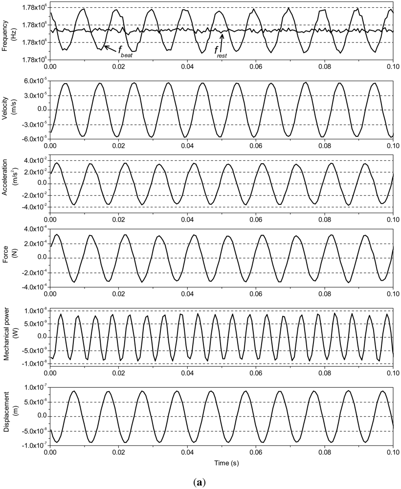
All the actuators are discharged before tested. In the figures hereinafter shown, the data set obtained from the experiment of 0.1 s is shown. Since the driven signal and data processing for three actuators are same, <xref ref-type="fig" rid="f3-sensors-12-11559">Figure 3</xref> only shows the mechanical and electrical quantities of P1, which are measured by using our experimental setup. <xref ref-type="fig" rid="f3-sensors-12-11559">Figure 3(a)</xref> shows the frequencies <italic>f<sub>rest</sub>, f<sub>beat</sub></italic> and the other mechanical quantities, such us velocity, acceleration, force, mechanical power and displacement of actuator P1, calculated from the frequencies. The mechanical power is calculated as the product of force and velocity. <xref ref-type="fig" rid="f3-sensors-12-11559">Figure 3(b)</xref> shows the electrical quantities, voltage, current and electric power applied on P1. Usually, PZT actuator is considered as a capacitance load [<xref ref-type="bibr" rid="b20-sensors-12-11559">20</xref>,<xref ref-type="bibr" rid="b21-sensors-12-11559">21</xref>]. The phase difference between voltage and current is approximately 80.9° in <xref ref-type="fig" rid="f3-sensors-12-11559">Figure 3(b)</xref>. This is because the phase difference is influenced by the back-emf, due to the hysteresis [<xref ref-type="bibr" rid="b22-sensors-12-11559">22</xref>,<xref ref-type="bibr" rid="b23-sensors-12-11559">23</xref>].</p>
<p>
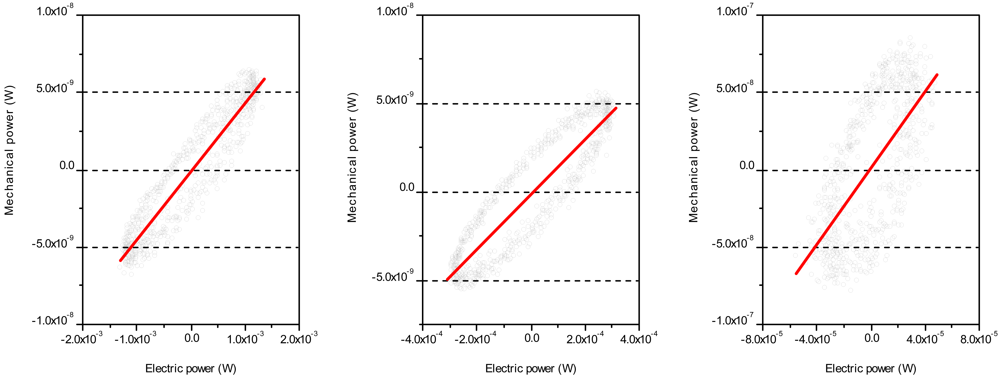
The relationships between the instantaneous mechanical power <italic>M<sub>p</sub></italic> and instantaneous electrical power <italic>E<sub>p</sub></italic> of P1, P2 and P3 (from left-to-right) are shown in <xref ref-type="fig" rid="f4-sensors-12-11559">Figure 4</xref>. The regression lines of P1, P2 and P3 are <italic>M<sub>p</sub></italic> = 4.4 × 10<sup>−6</sup><italic>E<sub>p</sub></italic> − 7.27 × 10<sup>−11</sup>, <italic>M<sub>p</sub></italic> = 1.56 × 10<sup>−5</sup><italic>E<sub>p</sub></italic> + 5.53 × 10<sup>−11</sup> and <italic>M<sub>p</sub></italic> = 1.24 × 10<sup>−3</sup><italic>E<sub>p</sub></italic> + 1.4 × 10<sup>−9</sup>, respectively. The results show that small size of actuator can transform electric power into mechanical power more effectively. The efficiency of converting average power of electrical (<italic>E<sub>ave</sub></italic>) power to mechanical (<italic>M<sub>ave</sub></italic>) power of P1, P2 and P3 (<italic>M<sub>ave</sub>/E<sub>ave</sub></italic>) are 4.8 × 10<sup>−7</sup>, 7.25 × 10<sup>−6</sup> and 8.63 × 10<sup>−5</sup>, respectively. Most of the electric energy seems to be dissipated in the form of heat.
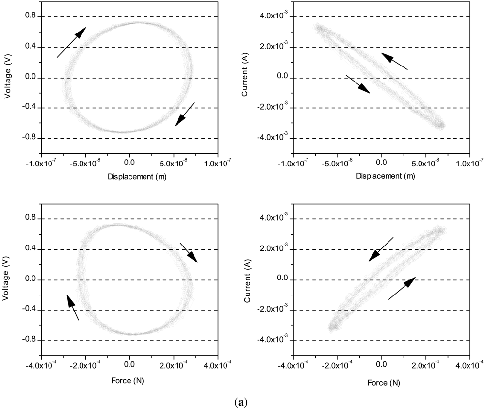
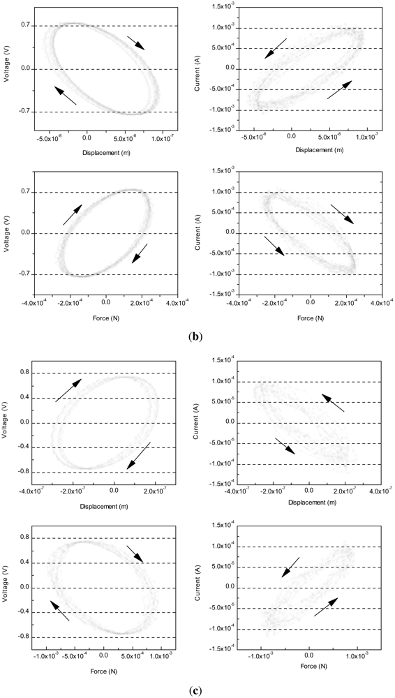
</p>
<p><xref ref-type="fig" rid="f5-sensors-12-11559">Figure 5</xref> shows a set of figures of voltage and current against displacement and force of the three actuators. These figures show that the hysteresis of the PZT actuators caused by voltage is larger than current. Particularly, the long length in the axial direction causes large hysteresis as shown in <xref ref-type="fig" rid="f5-sensors-12-11559">Figure 5(a,c)</xref>. The high reproducibility of data indicates that the hysteresis loops are congruent due to the input variation within the same range.
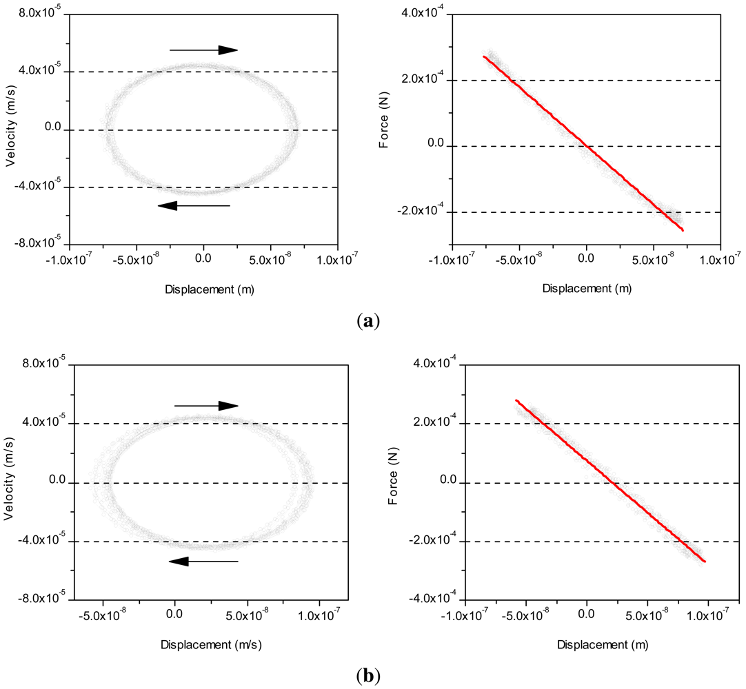
</p>
<p><xref ref-type="fig" rid="f6-sensors-12-11559">Figure 6</xref> shows the velocity and force against displacement of the actuators P1, P2 and P3. Ten periods of reciprocating motion are recorded during this experiment. The reproducibility of data is very high during reciprocating motion. The regression line of force <italic>F</italic> against displacement <italic>x</italic> is <italic>F</italic> = 3.02 × 10<sup>−7</sup> − −3.56 × 10<sup>3</sup><italic>x</italic> of P1, <italic>F</italic> = 7.35 × 10<sup>−5</sup> − −3.54 × 10<sup>3</sup><italic>x</italic> of P2 and <italic>F</italic> = −1.15 × 10<sup>−4</sup> − −3.49 × 10<sup>3</sup><italic>x</italic> of P3. From <xref ref-type="fig" rid="f6-sensors-12-11559">Figure 6</xref>, the actuators can be regarded as a spring with spring constant about 3.56 × 10<sup>3</sup><italic>N/m</italic> of P1 (<italic>k<sub>p</sub></italic><sub>1</sub>), 3.54 × 10<sup>3</sup><italic>N/m</italic> of P2 (<italic>k<sub>p</sub></italic><sub>2</sub>) and 3.49 × 10<sup>3</sup><italic>N/m</italic> of P3 (<italic>k<sub>p</sub></italic><sub>3</sub>). In sinusoidal operation, the spring constant <italic>k</italic> can be concluded as: <italic>k</italic> = 4<italic>π</italic><sup>2</sup><italic>m<sub>eff</sub>f</italic><sup>2</sup> from manufacturer, where <italic>f</italic> is the operation frequency, <italic>m<sub>eff</sub></italic> is the effective mass which relates to the loading and measuring point [<xref ref-type="bibr" rid="b7-sensors-12-11559">7</xref>]. If the measuring point is assumed at the tip of PZT actuator, then <italic>m<sub>eff</sub></italic> is considered as the mass of attachment, and <italic>k</italic> is equal to 3.58 × 10<sup>3</sup><italic>N/m</italic>, which is 0.56% higher than <italic>k<sub>p</sub></italic><sub>1</sub>, 1.12% higher than <italic>k<sub>p</sub></italic><sub>2</sub> and 2.58% higher than <italic>k<sub>p</sub></italic><sub>3</sub>. It may be because the measuring point where the acceleration is measured by interferometer is not equal to the tip of PZT actuator. In other words, this error may be caused by the mass between the tip of PZT actuator and the measuring point. The correlation coefficients of the fitting line in <xref ref-type="fig" rid="f6-sensors-12-11559">Figure 6</xref> are higher than 0.9, indicating a very well linear relationship between force and displacement generated by the actuator.</p>
<p>Using the proposed method, the electro-mechanical characteristics of PZT actuators which are being driven can be measured easily and accurately. Force, which acts on the mass attached to the actuator under test, is measured as the inertial force of the mass itself, <italic>i.e., F</italic> = <italic>Ma</italic>. This is the most significant compared with other conventional methods. In this paper, only three sizes of stack piezo-stack actuators are tested. The developed method can be easily applied to evaluate the dynamic characteristics of different type of actuators and to evaluate the actuator driven by different types of excitation (e.g., changing the waveform, frequency or amplitude of the drive signal). This experiment is also able to calibrate actuators and estimate a mass whose inertial force can be measured by the calibration using the actuators.</p>
<p>The three dimensional measurement of the actuator can be realized by means of introducing three interferometers with three signal beams, which are not in the same plane and introduced to the CC attached to the actuator. Each signal beam has the sensitivity only for the component of the movement of the optical center (OC) of the CC of the signal beam's direction. If the gravity center (GC) of the attached mass coincides with the optical center (OC) of the CC, then the force component along each signal beam can be calculated as the product of the mass and the acceleration of the OC along the direction of each signal beam.</p>
<p>Precision measurements of the electrical and mechanical characteristics of the actuator should contribute to understanding the mechanism of the actuator and realizing more precision controllability of the actuator.</p></sec>
<sec sec-type="conclusions">
<label>4.</label>
<title>Conclusions</title>
<p>A precision method for evaluating the electrical and mechanical characteristics of actuators is proposed and demonstrated by evaluating the characteristics of three PZT actuators with difference size which are being driven. The main feature of the proposed method is that only two physical quantities are needed to be measured. One is Doppler frequency shift and the other is mass. Compared with above-mentioned method, force transducer, displacement transducer and known hold structure are not needed in this method. This method will be useful for better understanding the dynamic characteristics of PZT actuators during motion and for precisely controlling its position under dynamic conditions.</p></sec></body>
<back>
<ack>
<p>This work was supported in part by a research-aid fund of the Asahi Glass Foundation, a research-aid fund of the NSK. Foundation for the Advancement of Mechatronics (NSK-FAM) and the Grant-in-Aid for Scientific Research (B) 24360156(KAKENHI 24360156).</p></ack>
<ref-list>
<title>References</title>
<ref id="b1-sensors-12-11559"><label>1.</label><citation citation-type="journal"><person-group person-group-type="author"><name><surname>Juuti</surname><given-names>J.</given-names></name><name><surname>Kordäs</surname><given-names>K.</given-names></name><name><surname>Lonnakko</surname><given-names>R.</given-names></name><name><surname>Moilanen</surname><given-names>V.P.</given-names></name><name><surname>Leppävuori</surname><given-names>S.</given-names></name></person-group><article-title>Mechanically amplified large displacement piezoelectric actuators</article-title><source>Sens. Actuat. A: Phys.</source><year>2005</year><volume>120</volume><fpage>225</fpage><lpage>231</lpage><pub-id pub-id-type="doi">10.1016/j.sna.2004.11.016</pub-id></citation></ref>
<ref id="b2-sensors-12-11559"><label>2.</label><citation citation-type="journal"><person-group person-group-type="author"><name><surname>Liu</surname><given-names>Y.T.</given-names></name><name><surname>Fung</surname><given-names>R.T.</given-names></name><name><surname>Wang</surname><given-names>C.C.</given-names></name></person-group><article-title>Precision position control using combined piezo-VCM actuators</article-title><source>Precis. Eng.</source><year>2005</year><volume>29</volume><fpage>411</fpage><lpage>422</lpage><pub-id pub-id-type="doi">10.1016/j.precisioneng.2004.12.009</pub-id></citation></ref>
<ref id="b3-sensors-12-11559"><label>3.</label><citation citation-type="journal"><person-group person-group-type="author"><name><surname>Madhav</surname><given-names>A.</given-names></name><name><surname>Soh</surname><given-names>C.</given-names></name></person-group><article-title>An electromechanical impedance model of a piezoceramic transducer-structure in the presence of thick adhesive bonding</article-title><source>Smart Mater. Struct.</source><year>2007</year><volume>16</volume><pub-id pub-id-type="doi">10.1088/0964-1726/16/3/014</pub-id></citation></ref>
<ref id="b4-sensors-12-11559"><label>4.</label><citation citation-type="journal"><person-group person-group-type="author"><name><surname>Liang</surname><given-names>C.</given-names></name><name><surname>Sun</surname><given-names>F.P.</given-names></name><name><surname>Rogers</surname><given-names>C.A.</given-names></name></person-group><article-title>Dynamic analysis of active material systems</article-title><source>J. Intell. Mater. Syst. Struct.</source><year>1997</year><volume>8</volume><fpage>323</fpage><lpage>334</lpage><pub-id pub-id-type="doi">10.1177/1045389X9700800405</pub-id></citation></ref>
<ref id="b5-sensors-12-11559"><label>5.</label><citation citation-type="journal"><person-group person-group-type="author"><name><surname>Giurgiutiu</surname><given-names>V.</given-names></name><name><surname>Rogers</surname><given-names>C.A.</given-names></name></person-group><article-title>Power and energy characteristics of soild-state induced-strain actuators for static and dynamic application</article-title><source>J. Intell. Mater. Syst. Struct.</source><year>1997</year><volume>8</volume><fpage>738</fpage><lpage>750</lpage><pub-id pub-id-type="doi">10.1177/1045389X9700800903</pub-id></citation></ref>
<ref id="b6-sensors-12-11559"><label>6.</label><citation citation-type="journal"><person-group person-group-type="author"><name><surname>Pomirleanu</surname><given-names>R.</given-names></name><name><surname>Giurgiutiu</surname><given-names>V.</given-names></name></person-group><article-title>Full-stroke static and dynamic analysis of high-power piezoelectric actuators</article-title><source>J. Intell. Mater. Syst. Struct.</source><year>2002</year><volume>13</volume><fpage>275</fpage><lpage>289</lpage><pub-id pub-id-type="doi">10.1177/104538902761696751</pub-id></citation></ref>
<ref id="b7-sensors-12-11559"><label>7.</label><citation citation-type="web"><article-title>Mechanical Considerations for Dynamic Operation of PZTs</article-title><comment>Available Online: <ext-link xlink:href="http://www.physikinstrumente.com/tutorial" ext-link-type="uri">http://www.physikinstrumente.com/tutorial</ext-link> (accessed on 23 August 2012)</comment></citation></ref>
<ref id="b8-sensors-12-11559"><label>8.</label><citation citation-type="confproc"><person-group person-group-type="author"><name><surname>Fouaidy</surname><given-names>M.</given-names></name><name><surname>Martinet</surname><given-names>G.</given-names></name><name><surname>Hammoudi</surname><given-names>N.</given-names></name><name><surname>Chatelet</surname><given-names>F.</given-names></name><name><surname>Blivet</surname><given-names>S.</given-names></name><name><surname>Olivier</surname><given-names>A.</given-names></name><name><surname>Saugnac</surname><given-names>H.</given-names></name></person-group><article-title>Full Characterization at Low Temperature of Piezoelectric Actuators Used for SRF Cavities Active Tuning</article-title><conf-name>Proceedings of the Particle Accelerator Conference 2005</conf-name><conf-loc>Knoxville, TN, USA</conf-loc><conf-date>16–20 May 2005</conf-date><fpage>728</fpage><lpage>730</lpage></citation></ref>
<ref id="b9-sensors-12-11559"><label>9.</label><citation citation-type="journal"><person-group person-group-type="author"><name><surname>Choi</surname><given-names>S.B.</given-names></name><name><surname>Hong</surname><given-names>S.B.</given-names></name><name><surname>Han</surname><given-names>Y.M.</given-names></name></person-group><article-title>Dynamic characteristics of intertial actuator featuring piezoelectric materials: Experimental verification</article-title><source>J. Sound Vib.</source><year>2007</year><volume>302</volume><fpage>1048</fpage><lpage>1056</lpage><pub-id pub-id-type="doi">10.1016/j.jsv.2007.01.010</pub-id></citation></ref>
<ref id="b10-sensors-12-11559"><label>10.</label><citation citation-type="journal"><person-group person-group-type="author"><name><surname>Tzen</surname><given-names>J.J.</given-names></name><name><surname>Jeng</surname><given-names>S.L.</given-names></name><name><surname>Chieng</surname><given-names>W.H.</given-names></name></person-group><article-title>Modeling of piezoelectric actuator for comensation and controller design</article-title><source>Precis. Eng.</source><year>2003</year><volume>27</volume><fpage>70</fpage><lpage>86</lpage><pub-id pub-id-type="doi">10.1016/S0141-6359(02)00183-6</pub-id></citation></ref>
<ref id="b11-sensors-12-11559"><label>11.</label><citation citation-type="journal"><person-group person-group-type="author"><name><surname>Moilanen</surname><given-names>H.</given-names></name><name><surname>Leppävuori</surname><given-names>S.</given-names></name></person-group><article-title>Laser interferometric measurement of displacement-field characteristics of piezoelectric actuators and actuator materials</article-title><source>Sens. Actuators A: Phys.</source><year>2001</year><volume>92</volume><fpage>326</fpage><lpage>334</lpage><pub-id pub-id-type="doi">10.1016/S0924-4247(01)00591-X</pub-id></citation></ref>
<ref id="b12-sensors-12-11559"><label>12.</label><citation citation-type="journal"><person-group person-group-type="author"><name><surname>Zhang</surname><given-names>D.H.</given-names></name><name><surname>Yu</surname><given-names>Y.G.</given-names></name><name><surname>Ye</surname><given-names>H.Y.</given-names></name></person-group><article-title>Measuring the dynamic performance of PZT using self-mixing interference vibrometer</article-title><source>J. Optoelectron. Laser</source><year>2005</year><volume>16</volume><fpage>714</fpage><lpage>717</lpage><comment>in Chinese</comment></citation></ref>
<ref id="b13-sensors-12-11559"><label>13.</label><citation citation-type="journal"><person-group person-group-type="author"><name><surname>Fujii</surname><given-names>Y.</given-names></name></person-group><article-title>Measurement of the electrical and mechanical response of a force transducer against impact forces</article-title><source>Rev. Sci. Instrum.</source><year>2006</year><volume>77</volume><fpage>185108:1</fpage><lpage>185108:5</lpage></citation></ref>
<ref id="b14-sensors-12-11559"><label>14.</label><citation citation-type="journal"><person-group person-group-type="author"><name><surname>Fujii</surname><given-names>Y.</given-names></name></person-group><article-title>Proposal for a step response evaluation method for force transducers</article-title><source>Meas. Sci. Technol.</source><year>2003</year><volume>14</volume><fpage>1741</fpage><lpage>1746</lpage><pub-id pub-id-type="doi">10.1088/0957-0233/14/10/301</pub-id></citation></ref>
<ref id="b15-sensors-12-11559"><label>15.</label><citation citation-type="journal"><person-group person-group-type="author"><name><surname>Fujii</surname><given-names>Y.</given-names></name></person-group><article-title>A method for calibrating force transducers against oscillation force</article-title><source>Meas. Sci. Technol.</source><year>2003</year><volume>14</volume><fpage>1259</fpage><lpage>1264</lpage><pub-id pub-id-type="doi">10.1088/0957-0233/14/8/310</pub-id></citation></ref>
<ref id="b16-sensors-12-11559"><label>16.</label><citation citation-type="journal"><person-group person-group-type="author"><name><surname>Fujii</surname><given-names>Y.</given-names></name></person-group><article-title>Frictional characteristics of an aerostatic linear bearing</article-title><source>Tribol. Int.</source><year>2006</year><volume>39</volume><fpage>888</fpage><lpage>896</lpage><pub-id pub-id-type="doi">10.1016/j.triboint.2005.07.040</pub-id></citation></ref>
<ref id="b17-sensors-12-11559"><label>17.</label><citation citation-type="journal"><person-group person-group-type="author"><name><surname>Fujii</surname><given-names>Y.</given-names></name><name><surname>Hessling</surname><given-names>J.P.</given-names></name></person-group><article-title>Frequency estimation method from digitized waveform</article-title><source>Exp. Tech.</source><year>2009</year><volume>33</volume><fpage>64</fpage><lpage>69</lpage><pub-id pub-id-type="doi">10.1111/j.1747-1567.2008.00421.x</pub-id></citation></ref>
<ref id="b18-sensors-12-11559"><label>18.</label><citation citation-type="journal"><person-group person-group-type="author"><name><surname>Fujii</surname><given-names>Y.</given-names></name></person-group><article-title>Microforce materials tester based on the levitation mass method</article-title><source>Meas. Sci. Technol.</source><year>2007</year><volume>18</volume><fpage>1678</fpage><lpage>1682</lpage><pub-id pub-id-type="doi">10.1088/0957-0233/18/6/S02</pub-id></citation></ref>
<ref id="b19-sensors-12-11559"><label>19.</label><citation citation-type="journal"><person-group person-group-type="author"><name><surname>Fujii</surname><given-names>Y.</given-names></name><name><surname>Maru</surname><given-names>K.</given-names></name><name><surname>Jin</surname><given-names>T.</given-names></name></person-group><article-title>Method for evaluating the electrical and mechanical characteristics of a voice coil actuator</article-title><source>Precis. Eng.</source><year>2010</year><volume>34</volume><fpage>802</fpage><lpage>806</lpage><pub-id pub-id-type="doi">10.1016/j.precisioneng.2010.04.003</pub-id></citation></ref>
<ref id="b20-sensors-12-11559"><label>20.</label><citation citation-type="journal"><person-group person-group-type="author"><name><surname>Ma</surname><given-names>Y.T.</given-names></name><name><surname>Huang</surname><given-names>L.</given-names></name><name><surname>Shao</surname><given-names>W.W.</given-names></name></person-group><article-title>New open loop control improves linearity of piezoelectric actuators</article-title><source>Adv. Mater. Res.</source><year>2010</year><volume>34</volume><fpage>520</fpage><lpage>524</lpage></citation></ref>
<ref id="b21-sensors-12-11559"><label>21.</label><citation citation-type="journal"><person-group person-group-type="author"><name><surname>Miysako</surname><given-names>T.</given-names></name><name><surname>Trinh</surname><given-names>B.N.</given-names></name><name><surname>Onoue</surname><given-names>M.</given-names></name><name><surname>Kaneda</surname><given-names>T.</given-names></name><name><surname>Tue</surname><given-names>P.T.</given-names></name><name><surname>Tokumits</surname><given-names>E.</given-names></name><name><surname>Shimoda</surname><given-names>T.</given-names></name></person-group><article-title>Ferroelectric-gate thin-film transistor fabricated by total solution deposition process</article-title><source>Jpn. J. Appl. Phys.</source><year>2011</year><volume>50</volume><pub-id pub-id-type="doi">10.1143/JJAP.50.04DD09</pub-id></citation></ref>
<ref id="b22-sensors-12-11559"><label>22.</label><citation citation-type="journal"><person-group person-group-type="author"><name><surname>Royston</surname><given-names>J.T.</given-names></name></person-group><article-title>Modeling and measurement of nonlinear dynamic behavior in piezoelectric ceramics with application to 1-3 composites</article-title><source>J. Acoust. Soc. Am.</source><year>1998</year><volume>104</volume><fpage>2814</fpage><lpage>2827</lpage><pub-id pub-id-type="doi">10.1121/1.423866</pub-id></citation></ref>
<ref id="b23-sensors-12-11559"><label>23.</label><citation citation-type="journal"><person-group person-group-type="author"><name><surname>Goldfard</surname><given-names>M.</given-names></name><name><surname>Celanovic</surname><given-names>N.</given-names></name></person-group><article-title>Modeling piezoelectric stack actuators for control of micromanipulation</article-title><source>IEEE Control Syst.</source><year>1997</year><volume>17</volume><fpage>69</fpage><lpage>79</lpage><pub-id pub-id-type="doi">10.1109/37.588158</pub-id></citation></ref></ref-list>
<sec sec-type="display-objects">
<title>Figures and Table</title>
<fig id="f1-sensors-12-11559" position="float">
<label>Figure 1.</label>
<caption>
<p>Experimental setup.</p></caption>
<graphic xlink:href="sensors-12-11559f1.gif"/></fig>
<fig id="f2-sensors-12-11559" position="float">
<label>Figure 2.</label>
<caption>
<p>Photographs of measurement system.</p></caption>
<graphic xlink:href="sensors-12-11559f2.gif"/></fig>
<fig id="f3-sensors-12-11559" position="float">
<label>Figure 3.</label>
<caption>
<p>(<bold>a</bold>) The frequency of beat and rest laser beam, and mechanical quantities of PZT actuator P1; (<bold>b</bold>) The electrical quantities of PZT actuator P1.</p></caption>
<graphic xlink:href="sensors-12-11559f3a.gif"/>
<graphic xlink:href="sensors-12-11559f3b.gif"/></fig>
<fig id="f4-sensors-12-11559" position="float">
<label>Figure 4.</label>
<caption>
<p>The instantaneous mechanical power changed against instantaneous electric power of P1, P2 and P3 from left to right.</p></caption>
<graphic xlink:href="sensors-12-11559f4.gif"/></fig>
<fig id="f5-sensors-12-11559" position="float">
<label>Figure 5.</label>
<caption>
<p>Voltage and current applied on the actuator, against displacement and force; (<bold>a</bold>) P1; (<bold>b</bold>) P2 and (<bold>c</bold>) P3.</p></caption>
<graphic xlink:href="sensors-12-11559f5a.gif"/>
<graphic xlink:href="sensors-12-11559f5b.gif"/></fig>
<fig id="f6-sensors-12-11559" position="float">
<label>Figure 6.</label>
<caption>
<p>Velocity and force changed against displacement; (<bold>a</bold>) P1; (<bold>b</bold>) P2 and (<bold>c</bold>) P3.</p></caption>
<graphic xlink:href="sensors-12-11559f6b.gif"/>
<graphic xlink:href="sensors-12-11559f6b.gif"/></fig>
<table-wrap id="t1-sensors-12-11559" position="float">
<label>Table 1.</label>
<caption>
<p>Specification of PZT actuators P1, P2 and P3.</p></caption>
<table frame="hsides" rules="groups">
<thead>
<tr>
<th align="left" valign="top"><bold>Name</bold></th>
<th align="center" valign="top"><bold>Dimensions</bold></th>
<th align="center" valign="top"><bold>Displacement(100V)</bold></th>
<th align="center" valign="top"><bold>Capacitance</bold></th></tr></thead>
<tbody>
<tr>
<td align="left" valign="top">P1</td>
<td align="center" valign="top">10 × 10 × 18 mm</td>
<td align="center" valign="top">15 <italic>μ</italic>m</td>
<td align="center" valign="top">6.59 <italic>μ</italic>F</td></tr>
<tr>
<td align="left" valign="top">P2</td>
<td align="center" valign="top">6.5 × 6.5 × 18 mm</td>
<td align="center" valign="top">15 <italic>μ</italic>m</td>
<td align="center" valign="top">1.6 <italic>μ</italic>F</td></tr>
<tr>
<td align="left" valign="top">P3</td>
<td align="center" valign="top">3.5 × 4.5 × 10 mm</td>
<td align="center" valign="top">9.1 <italic>μ</italic>m</td>
<td align="center" valign="top">0.18 <italic>μ</italic>F</td></tr></tbody></table></table-wrap></sec></back></article>
