Next Generation AT-Cut Quartz Crystal Sensing Devices

Abstract
: Generally, AT-cut quartz crystals have a limited scope of use when it comes to high-precision measurement of very small impedance changes due to their nonlinear frequency-temperature characteristics in the range between 0 °C and 50 °C. The new method improving quartz oscillator frequency-temperature characteristic compensation is switching between two impedance loads. By modifying the oscillator circuit with two logic switches and two impedance loads, the oscillator can switch oscillation between two resonance frequencies. The difference in resonance frequencies compensates the frequency-temperature characteristics influence as well as the influence of offset and quartz crystal ageing. The experimental results show that the new approach using the switching method highly improves second-to-second frequency stability from ±0.125 Hz to ±0.00001 Hz and minute-to-minute frequency stability from 0.1 Hz to 0.0001 Hz, which makes the high-precision measurement of aF and fH changes possible.1. Introduction
Quartz crystal temperature characteristics are of primary importance in high-precision measurement of small impedances. Generally, sensor techniques involve capacitance and inductance changes, particularly for the measurement of pico extensions, hollow pico-sphere magnetic properties, novel magnetic pico-adsorbents, displacement field forces, humidity sensors, Van der Waals force measurement, etc.
The application of quartz crystals for the measurement purposes using external electrical elements (L, C) that influence electrical equivalent circuit has been suggested in past articles dealing with capacitive and inductive measurements as well as with the use of two single quartz crystals [1–3]. Also described were the quartz crystal C0 capacitance compensation and high improvement of pulling sensitivity. The latter requires very stable frequency-temperature characteristics, determining the accuracy within a given measurement range. And even if an AT-cut quartz crystal with the angle of cut = 0 is selected, the temperature dependence of some ppm can still be registered [1–5].
Capacitive and inductive changes with the resolution up to 0.01 pF or 0.01 nH can also be measured with LCR instruments (Hewlett-Packard 4284A-Precision LCR meter, 20 Hz–1 MHz, 0.05%), however, once again the second-to-second and minute-to minute frequency stability plays an important role [6,7].
This research focuses on the temperature and ageing characteristics compensation of AT fundamental quartz crystals (5 MHz) operating over the measurement temperature range of 0 °C to 50 °C. Crystals fabricated in this manner exhibit excellent frequency versus temperature stability between 10 °C and 40 °C and also good start-up. For smaller frequency change measurement, however, the improvement of the frequency-temperature stability in this temperature range is of vital importance [8–10].
2. The Switching Method of Quartz Sensing Device
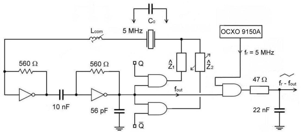
The new measurement method is based on a quartz oscillator [11] and the switching part of the circuit, alternatively switching complex impendances Ẑ1 and Ẑ2 in the oscillator circle with the signal of ones and zeros Q and Q̄) representing a novelty in this research (Figure 1).
The output fout represents the output oscillator frequency which is synchronously measured with regard to the switch Q and Q̄). The switch time duration Q is 1 s. When the complex impedances Ẑ1 and Ẑ2 are equal, then fout(Q) and fout(Q̄) are equal too. For this purpose, a special AT fundamental quartz crystal (cutting angle 0) operating near the antiresonance frequency 5 MHz has been selected. In the oscillator circuit, the inductance Lcom is in series with the quartz crystal and together with the compensation method (C0) increases and linearilizes the frequency pulling range. The quartz crystal’s parasitic capacitance Co represents the capacitance of the crystal element and the holder [2]. Complex impedances are the same and can be capacitive (1/jωC) or inductive (jωL) in character. When the complex impedances are the same, fout remains the same at Q and Q̄ and depends on the quartz crystal resonant frequency f0, AT-cut quartz crystal temperature characteristics Δf (T) and its ageing Δf (t). However, when the complex impedances are different, the frequency fout depends on the quartz crystal resonant frequency f0, the ΔC2 or ΔL2 change (frequency pulling) and AT-cut quartz crystal temperature characteristics Δf (T) and its ageing Δf (t). In case of the difference of both frequencies for Q and Q̄, Δf (T) and Δf (t) compensate because only one quartz characteristics is involved [9].
The ouput frequencies for both switching conditions are:
When joining f0 and Δf (ΔC2) (Equation 4), we get Equation 5 [1,2]. The particularity of this equation lies in the fact that it takes into account the compensation C0 and at the same time linearizes the quartz characteristics due to the ΔC2 change (Figure 1) [1,2,12].
| k = 1, 2, 3 | |
| L and C | |
| Lcom | compensation inductance, |
| Co | parasitic capacitance of the crystal element and holder, |
| f0 | quartz crystal series resonant frequency. |
The pulling sensitivity in Equation 5 can be set with the value k, achieving at the same time simultaneous dependance linearilization Δf (C2) [1,2]. We get the frequency difference representing the temperature compensated and linear value of the frequency, which depends uniquely on the ΔC2 change. This means that it is dependent neither on the AT-cut quartz crystal temperature characteristics Δf (T) nor its ageing Δf (t) and nor the circuit temperature characteristics influences [Equations (7–9)] [1,2]:
If Ẑ2 (Figure 1) is inductive in character, the equation would generally be similar with the inductance change ΔL2 [Equations (10) and (11)]:
While the specified counter accuracy (HM 8122) ±5 × 10⁻⁷ does not allow high precision measurements of small frequency changes at 5 MHz, the use of an additional reference frequency fr = 5 MHz (auxiliary OCXO oscillator) (Figure 1), of the frequency difference method (AND gate) and of the low pass filter enables very precise measurements of the frequency difference between the switches Q and Q̄. This output difference is defined with the Equation 12:
The switching from Q to Q̄ compensates the frequency fr, and consequently its frequency stability as well. The filter time constant for the frequency elimination is determined with the following equation:
3. AT-Cut Quartz Crystal Temperature Characteristics
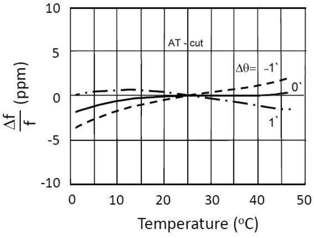
Due to their physical properties, AT-cut crystals are predominantly used in oscillator circuits. Their main advantage is the lower temperature sensitivity in the temperature range between 10 °C and 40 °C (Figure 2). The curves are represented as the cubical parabola with temperature intersection point lying between 25 °C and 35 °C, depending on the crystal cut angle and the mechanical construction. Equation 14 describes the crystal oscillation temperature frequency change (in ppm) with regard to the reference temperature [11–14]:
| T | environment temperature |
| Tref | reference temperature |
| A1 and A3 | coefficients determined with regard to the angle of the cut |
For higher accuracy, five measuring points (to measure the frequencies) or more may be necessary. By means of these, the best adapted cubical parabola is applied and the appropriate coefficients A1 and A3 determined. Nevertheless, this mathematical approximation is not precise enough for the high-precison measurements of small impedance changes [11–14].
4. Frequency Variation as Function of Time
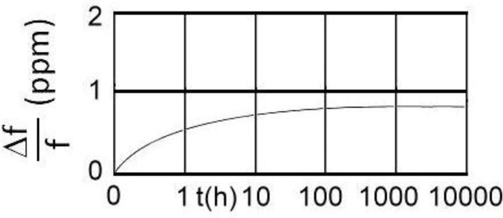
Frequency variation is normally considered in short term stability (second-to-second and minute-to-minute temperature characteristics) and long term stability over days, months or years, called ageing. The short term stability of a quartz crystal depends on the actual oscillator design and is totally controlled by the quartz crystal at low drive levels (30 μW). The ageing rate is substantially influenced by the cleanliness of the resonator, the stability of the inert gas filling and the security of the final sealing process. Ageing is naturally greater during the first part of the life of the crystal unit. The frequency ageing can often be described by function of the form of time t (Figure 3) [11–14].
It is necessary to distinguish between active and passive ageing. Active ageing is the frequency shift, when the crystal works under operating conditions—permanently oscillating in the circuit. Typically the ageing rates of the best cold weld crystals are less than ±1 ppm/year (10 °C to 40 °C). Passive ageing is the frequency shift during storage.
5. The Counter Error
Counter error Δf (counter error) occurs in the measurement of the frequency fout (Q and Q̄) (Figure 1). Typical counter (Programmable Counter/Timer HM 8122) accuracy is ±5 × 10⁻⁷ (through entire working temperature range +10 °C up to 40 °C), in 5 × 10⁻⁹/day after 48 hours continuous operation with crystal oven controlled (OCXO). Frequency repetition accuracy after 24 hours of “power off”: ±5 × 10⁻⁸. Resolution is determined as ±1 or 2 LSD, while frequency measurement accuracy is defined with the following term [6]:
The novel switching method highly reduces the influence of the short- and long-term accuracy of the above described counter due to the compensation of previously mentioned influences of a single quartz crystal and the circuit as well as the influence of the difference method using additional reference frequency fr = 5 MHz. Frequency fr is produced by oven controlled crystal oscillator (OCXO 9150A) with a short-term stability (1 s) 5 × 10⁻¹¹ (max) in the temperature range between 0 °C and 50 °C following the warm-up time of 30 min [15].
6. Experimental Results
The experimental data values in the 5 MHz quartz crystal equivalent circuit were measured by a HP 4194A impedance/gain-phase analyzer. The quartz crystal (HC-49/U) was selected due to its high Q value (Table 1) [14].
In Table 1, f0 represents the AT fundamental mode quartz crystal resonant frequency. R is series resistance and Qq is quality factor [1,2].
For this research a quartz switching oscillator circuit (Figure 1) was experimentally selected switching between impedances Ẑ1 and Ẑ2 with the frequency 1 Hz. The impedances in this research are defined as 1/jωC. The C values were in the range 2.5 pF to 40 pF. Within 2 s time, the counter measured both frequencies f (Q) and f (Q̄).
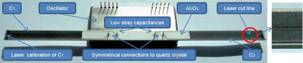
Two impedances Ẑ1 and Ẑ2 in the form of an open capacitor were used experimentally. The impedances were produced on a temperature stable material Al2O3 and are of the same capacitance C1 = C2 = 4pF (Figure 4). Capacitances were produced by laser cutting and measure 5 mm × 40 mm in dimension.
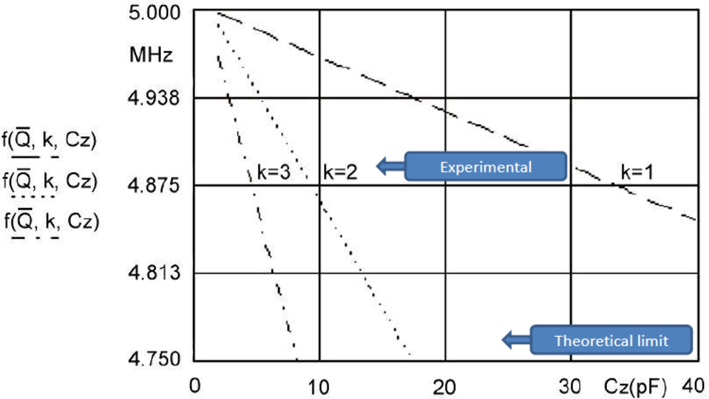
For three k values, three linearized characteristics and C0 compensation in the range of change C2 from 2.5 to 40 pF can be seen in Figure 5. The pulling sensitivity is highest at the value k = 3. For the temperature range between 0 °C and 50 °C (Figure 2) and k = 3 the experimentally measured frequency change results (Programmable Counter/Timer HM 8122) were ±0.00001 Hz (second-to-second stability) and ±0.0001 Hz (minute-to-minute stability) representing 100 times better results than those achieved by existing methods in a given temperature range (in cases where the crystal is not extra temperature stabilized). At values k = 1 and k = 2 the stability is better, however the pulling sensitivity is lower.
7. Conclusions
Experimental results show that the use of the switching method excellently compensates AT-cut frequency-temperature characteristics and highly improves second-to-second and minute-to-minute accuracy by ×100 for k = 1, 2, 3, depending on C0 compensation. This high frequency difference accuracy represents a novelty and a major advantage of the switching method discussed in the measurement of ato and femto ranges. With fine tuning of a series load compensation inductance Lcom connected in series with the crystal, the frequency of the oscillator is set to an appropriate output circuit frequency. It should also be emphasized that the exact pulling limits depend on the crystal’s Q value as well as the associated stray capacitances and the factor k. The inductance Lcom is determined from known stray capacitances and the known factor k.
The factors affecting frequency stability such as wide operating temperature range, ageing and drive level as well as all other crystal characteristics influencing the stability should also be considered because a stable oscillator circuit plays an important role in the frequency pulling sensitivity increase. Frequency stability also depends on the temperature coefficient of the compensation inductance Lcom material. Stability of the electronic circuit depends upon the circuit type and quality of its elements. It is also important that the drive level of the quartz crystal does not exceed 30 μW [7,12,14,16]. These results clearly show that the switching method for the next generation AT-cut quartz crystal sensing devices outperforms conventional measurement methods.
References
- Matko, V; Jezernik, K. Greatly Improved Small Inductance Measurement Using Quartz Crystal Parasitic Capacitance Compensation. Sensors 2010, 10, 3954–3960. [Google Scholar]
- Matko, V; Šafarič, R. Major Improvements of Quartz Crystal Pulling Sensitivity and Linearity Using Series Reactance. Sensors 2009, 9, 8263–8270. [Google Scholar]
- Matko, V. Comparison of Frequency Pullability in Oscillators Using a Single AT-Cut Quartz Crystal and Those Using Two Single AT Cut Crystals Connected in Parallel with a Series Load Capacitance or Series Load Inductance. Sensors 2006, 6, 746–755. [Google Scholar]
- Webster, JG. The Measurement, Instrumentation, and Sensors, Capacitance Measurement, Inductance Measurement; CRC Press: Boca Raton, FL, USA, 1999; p. 50. [Google Scholar]
- Stanford Research Systems. Quartz Crystal Microbalance Theory, Available online: http://www.thinksrs.com/downloads/PDFs/ApplicationNotes/QCMTheoryapp.pdf (accessed on 28 September 2009).
- Hameg Instruments, Specification of HM8122; Hameg Instruments: Mainhausen, Germany, 2008.
- Rutman, J; Walls, FL. Characterization of Frequency Stability in Precision Frequency Sources. IEEE Trans. Instrum. Meas 1991, 79, 952–960. [Google Scholar]
- ATMEL. Analyzing the Behavior of an Oscillator and Ensuring Good Start-Up, Available online: http://www.atmel.com/dyn/resources/prod_documents/doc4363.pdf (accessed on 28 September 2009).
- Philips Electronics, Oscillator Start-Up Time; Application Note AN97090; Philips Electronics: Eindhoven The Netherlands, 2001.
- Schrüfer, E. Electrical Measurement: Quartz as a Frequency Reference; Carl Hanser Verlag: München, Germany, 1992; pp. 405–412. [Google Scholar]
- Euroquartz. Quartz Oscillator Theory, Available online: http://www.euroquartz.co.uk (accessed on 28 September 2009).
- Kusters, JA; Vig, JR. Thermal Hysteresis in Quartz Resonators. In Proceedings of 44th Annual Symposium on Frequency Control; Baltimore, MD, USA; 23–25; May; 1990; pp. 165–175. [Google Scholar]
- Jauch Quartz GmbH. Quartz Crystal Theory, Available online: http://www.jauch.de/ablage/med_00000619_1193753698_Quartz%20Crystal%20Theory%202007.pdf (accessed on 28 September 2009).
- Lap-Tech Inc. Standard Frequency Components, Available online: http://www.laptech.com/ (accessed on 28 September 2009).
- Nihon Dempa Kogyo Co., Ltd. OCXO 9150A Data Sheet, Available online: http://www.datasheetarchive.com/915-datasheet.html.
- Dorf, RC. Introduction to Electric Circuits; John Wiley & Sons: New York, NY, USA, 1989; pp. 100–200. [Google Scholar]


© 2011 by the authors; licensee MDPI, Basel, Switzerland. This article is an open access article distributed under the terms and conditions of the Creative Commons Attribution license (http://creativecommons.org/licenses/by/3.0/).
Share and Cite
Matko, V. Next Generation AT-Cut Quartz Crystal Sensing Devices. Sensors 2011, 11, 4474-4482. https://doi.org/10.3390/s110504474
Matko V. Next Generation AT-Cut Quartz Crystal Sensing Devices. Sensors. 2011; 11(5):4474-4482. https://doi.org/10.3390/s110504474
Chicago/Turabian StyleMatko, Vojko. 2011. "Next Generation AT-Cut Quartz Crystal Sensing Devices" Sensors 11, no. 5: 4474-4482. https://doi.org/10.3390/s110504474
APA StyleMatko, V. (2011). Next Generation AT-Cut Quartz Crystal Sensing Devices. Sensors, 11(5), 4474-4482. https://doi.org/10.3390/s110504474