A Power-Efficient Bio-Potential Acquisition Device with DS-MDE Sensors for Long-Term Healthcare Monitoring Applications


Abstract
:1. Introduction
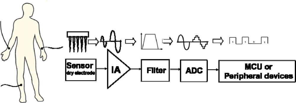
- Electrodes at several points on the human body;
- Analog front end circuits that amplify the bio-differential signals gathered by the electrodes;
- Analog-to-digital converter (ADC) that digitizes the amplified signals;
- Processing unit that manages and processes bio-differential signals;
- Monitoring software that records and displays data.
2. Materials and Methods
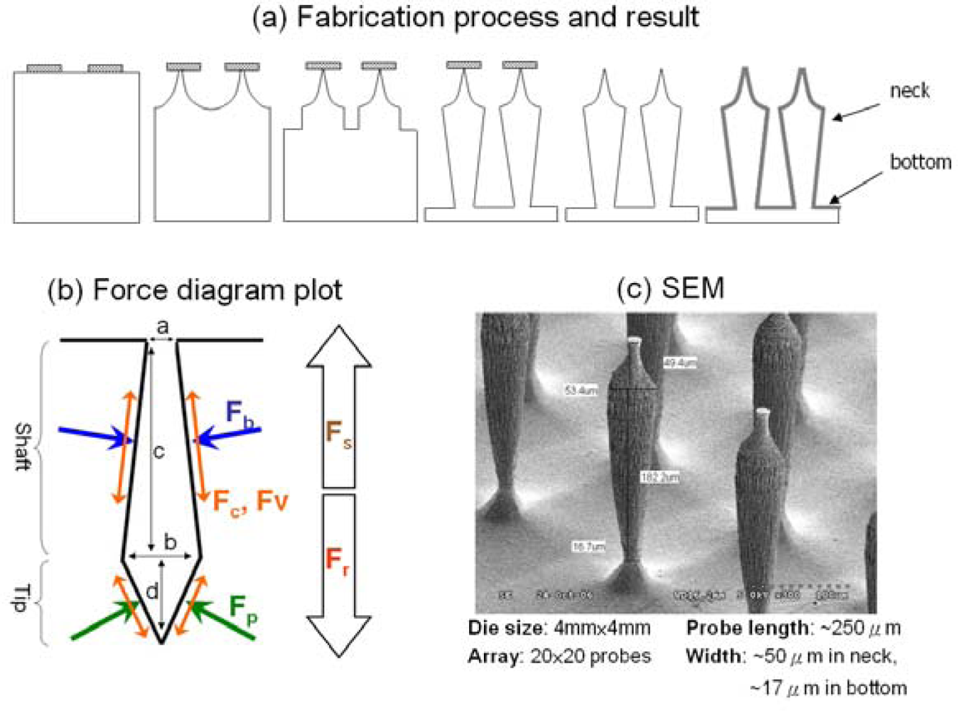
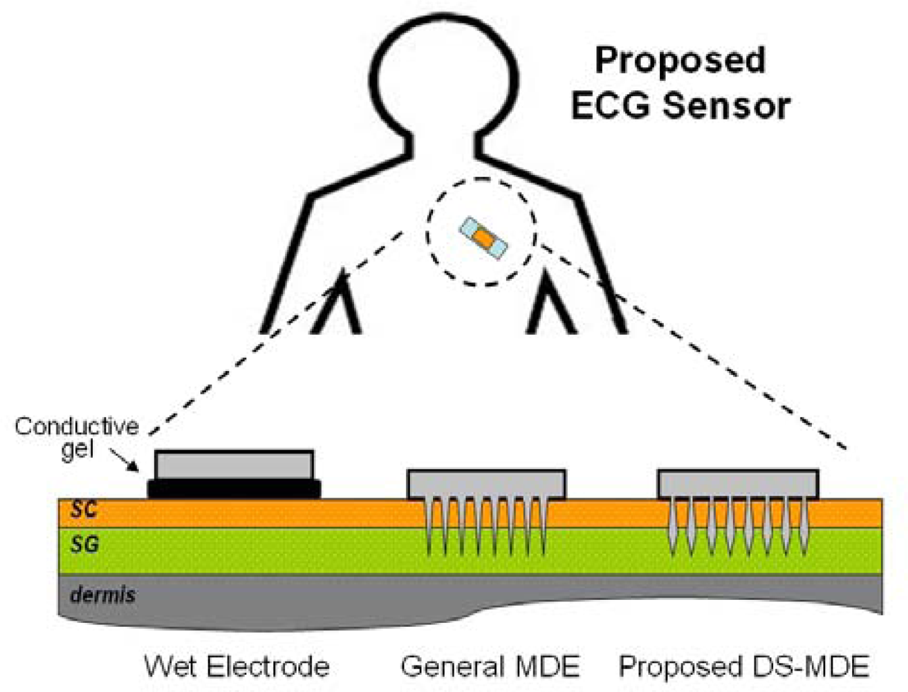
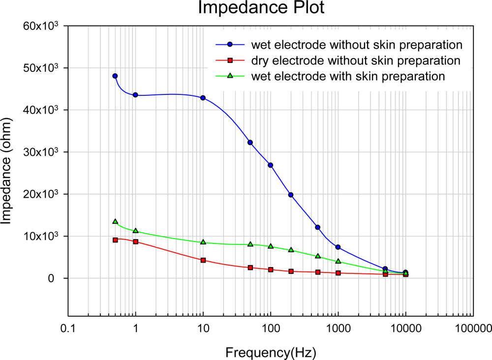
2.1. DS-MDE
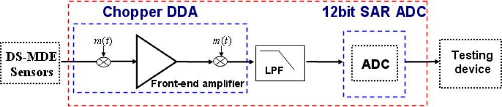
2.2. The proposed bio-potential acquisition circuits
- High CMRR to reject common mode noise.
- High input impedance property for DS-MDE sensors.
- Low noise DDA amplifier for enhancing better signal quality.
- Sufficient resolution for ECG acquisition.
- Low power dissipation for long-term monitoring.
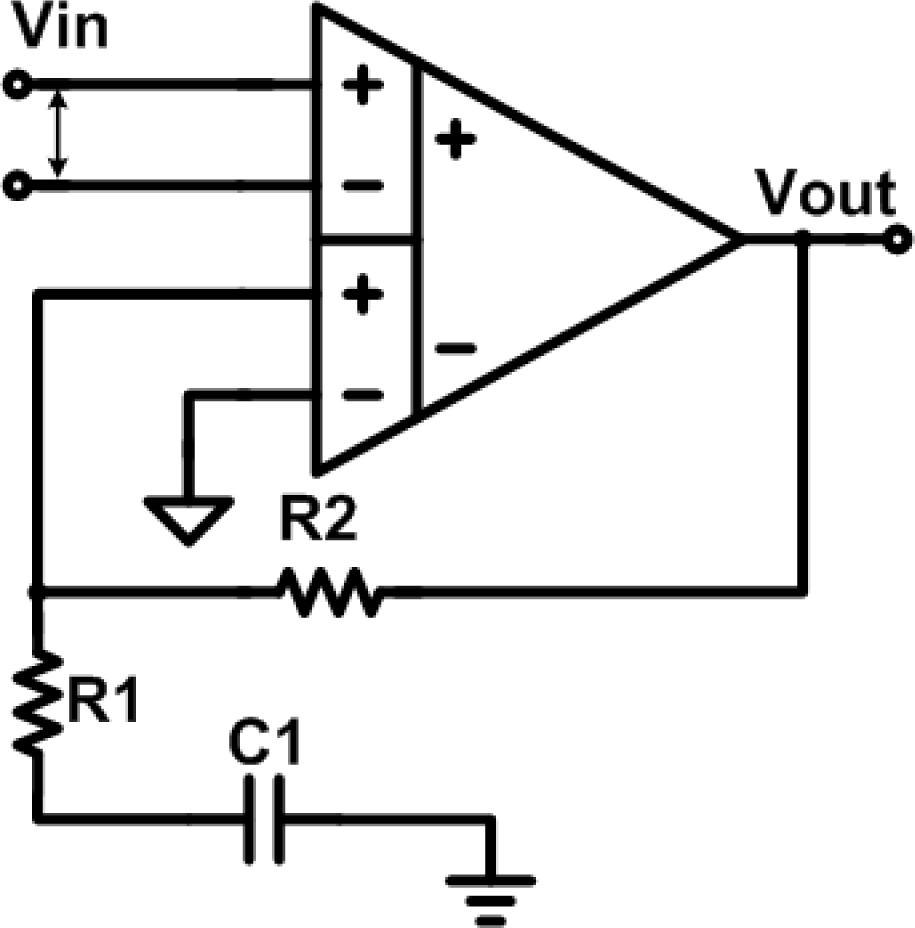
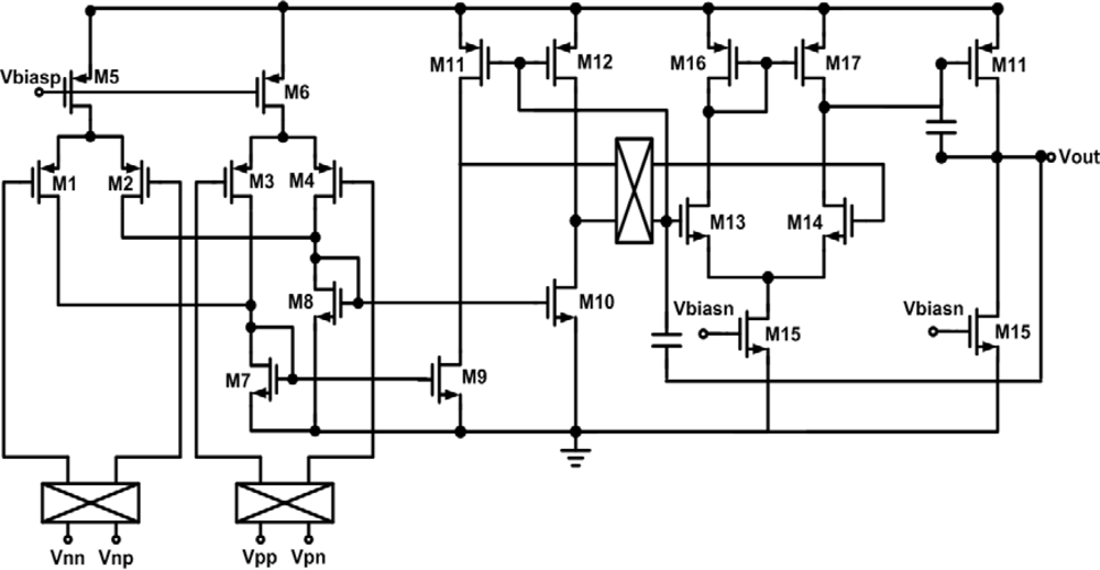
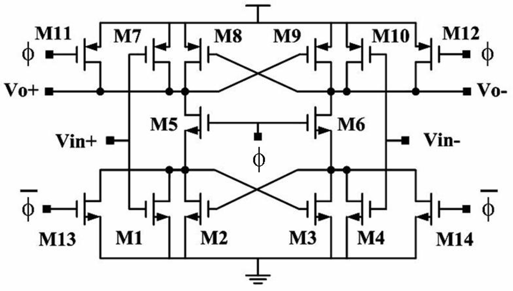
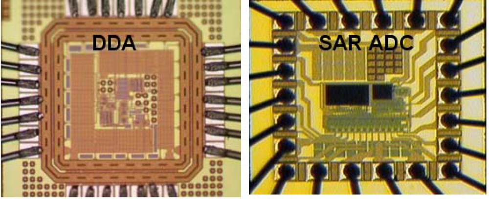
2.2.1. The implementation of the proposed bio-potential acquisition chip—DDA
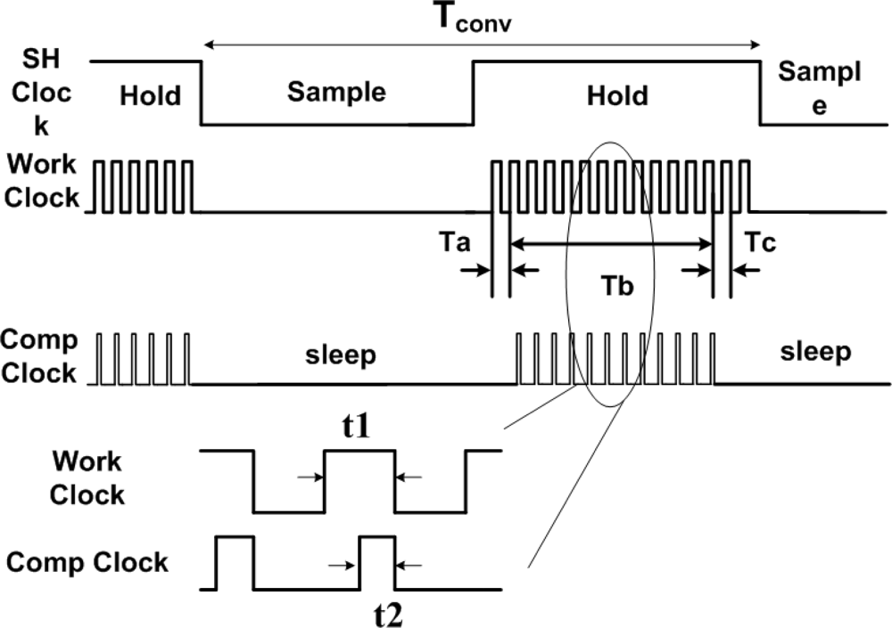
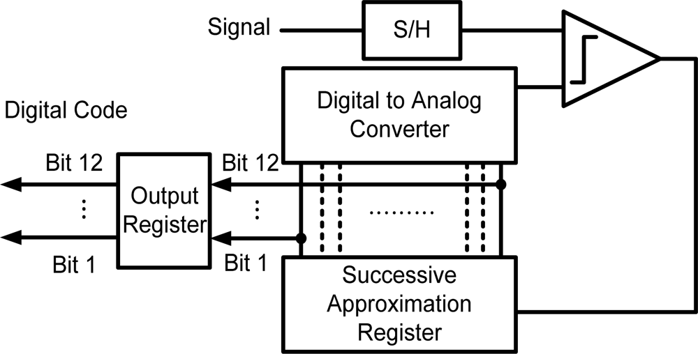
2.2.2. Implementation of the proposed bio-potential acquisition chip—ADC
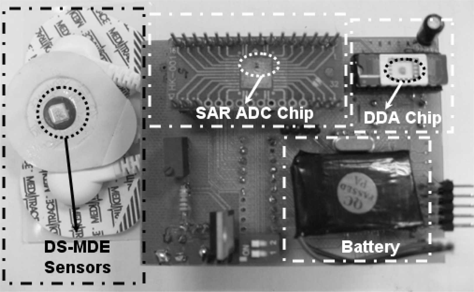
2.3. Peripheral devices for data transmission and storage
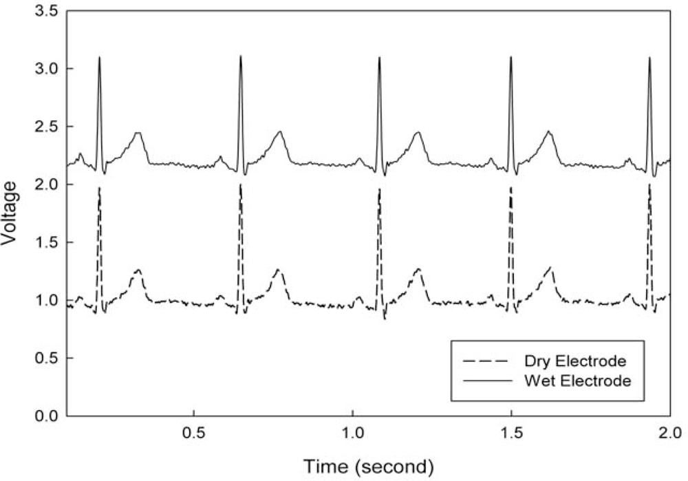
3. Experimental Results and Discussion
4. Conclusions
5. Acknowledgements
References
- Chang, C.L.; Chang, C.W; Hsu, C.M.; Luo, C.H.; Chiou, J.C. Power-Efficient Wireless Sensor for Physiological Signal Acquisition. J. Micro/Nanolith. MEMS MOEMS 2009, 8. [Google Scholar] [CrossRef]
- Proulx, J.; Clifford, R.; Sorensen, S.; Dah-Jye, L.; Archibald, J. Development and Evaluation of a Bluetooth EKG Monitoring Sensor. Proceedings of the 19th IEEE International Symposium on Computer-Based Medical Systems, Salt Lake City, UT, USA, June 22–23, 2006; pp. 507–511.
- Morais, R.; Fernandes, M.A.; Matos, S.G.; Serôdio, C.; Ferreira, P.J.S.G.; Reis, M.J.C.S. A ZigBee Multi-Powered Wireless Acquisition Device for Remote Sensing Applications in Precision Viticulture. Comput. Electron. Agric 2008, 62, 94–106. [Google Scholar]
- Breit, S.; Spieker, S.; Schulz, J.B.; Gasser, T. Long-Term EMG Recordings Differentiate between Parkinsonian and Essential Tremor. J. Neurol 2008, 255, 103–111. [Google Scholar]
- Fay, L.; Misra, V.; Sarpeshkar, R. A Micropower Electrocardiogram Amplifier. IEEE Trans. Biomed. Circ. Syst 2009, 3, 312–320. [Google Scholar]
- Griss, P.; Tolvanen-Laakso, H.K.; Merilainen, P.; Stemme, G. Characterization of Micromachined Spiked Biopotential Electrodes. IEEE Trans. Biomed. Eng 2002, 49, 597–604. [Google Scholar]
- Taheri, B.A.; Knight, R.T.; Smith, R.L. A Dry Electrode for EEG Recording. Electroencephalogr. Clin. Neurophysiol 1994, 90, 376–383. [Google Scholar]
- Griss, P.; Enoksson, P.; Stemme, G. Micromachined Barbed Spikes for Mechanical Chip Attachment. Sens. Actuat. A: Phys 2002, 95, 94–99. [Google Scholar]
- Harrison, R.R.; Watkins, P.T.; Kier, R.J.; Lovejoy, R.O.; Black, D.J.; Greger, B.; Solzbacher, F. A Low-Power Integrated Circuit for a Wireless 100-Electrode Neural Recording System. IEEE J. Solid-State Circ 2007, 42, 123–133. [Google Scholar]
- Denison, T.; Consoer, K.; Kelly, A.; Hachenburg, A.; Santa, W. A 2.2 W 94 nV/Hz, Chopper-Stabilized Instrumentation Amplifier for EEG Detection in Chronic Implants. Proceedings of IEEE International Solid-State Circuits Conference (ISSCC 2007), San Francisco, CA, USA, February 11–15, 2007; pp. 162–594.
- Aziz, J.N.Y.; Abdelhalim, K.; Shulyzki, R.; Genov, R.; Bardakjian, B.L.; Derchansky, M.; Serletis, D.; Carlen, P.L. 256-Channel Neural Recording and Delta Compression Microsystem With 3D Electrodes. IEEE J. Solid-State Circ 2009, 44, 995–1005. [Google Scholar]
- Teplan, M. Fundamental of EEG Measurement. Meas. Sci. Rev 2002, 2, 1–11. [Google Scholar]
- Miller, H.A.; Harrison, D.C. Biomedical Electrode Technology; Academic Press: New York, NY, USA, 1974. [Google Scholar]
- Griss, P.; Enoksson, P.; Tolvanen-Laakso, H.K.; Merilainen, P.; Ollmar, S.; Stemme, G. Micromachined Electrodes for Biopotential Measurements. J. Microelectromech. Syst 2001, 10, 10–16. [Google Scholar]
- Burke, M.J.; Gleeson, D.T. A Micropower Dry-Electrode ECG Preamplifier. IEEE Trans. Biomed. Eng 2000, 47, 155–162. [Google Scholar]
- Pallas-Areny, R.; Webster, J.G. AC Instrumentation Amplifier for Bioimpedance Measurements. IEEE Trans. Biomed. Eng 1993, 40, 830–833. [Google Scholar]
- Spinelli, E.M.; Pallas-Areny, R.; Mayosky, M.A. AC-Coupled Front-End for Biopotential Measurements. IEEE Trans. Biomed. Eng 2003, 50, 391–395. [Google Scholar]
- Spinelli, E.M.; Martinez, N.; Mayosky, M.A.; Pallas-Areny, R. A Novel Fully Differential Biopotential Amplifier with DC Suppression. IEEE Trans. Biomed. Eng 2004, 51, 1444–1448. [Google Scholar]
- Steyaert, M.S.J.; Sansen, W.M.C. A Micropower Low-Noise Monolithic Instrumentation Amplifier for Medical Purposes. IEEE J. Solid-State Circ 1987, 22, 1163–1168. [Google Scholar]
- Khan, A.A.; Al-Turaigi, M.A.; Ei-Ela, M.A. An Improved Current-Mode Instrumentation Amplifier with Bandwidth Independent of Gain. IEEE Trans. Instrum. Meas 1995, 44, 887–891. [Google Scholar]
- Brokaw, A.P.; Timko, M.P. An Improved Monolithic Instrumentation Amplifier. IEEE J. Solid-State Circ 1975, 10, 417–423. [Google Scholar]
- Martins, R.; Selberherr, S.; Vaz, F.A. A CMOS IC for Portable EEG Acquisition Systems. IEEE Trans. Instrum. Meas 1998, 47, 1191–1196. [Google Scholar]
- Franco, S. Design With Operational Amplifiers and Analog Integrated Circuits, 3rd ed; McGraw-Hill: New York, NY, USA, 2001; pp. 79–85. [Google Scholar]
- Yazicioglu, R.F.; Merken, P.; Puers, R.; Van Hoof, C. A 60 uW 60 nV/root Hz Readout Front-End for Portable Biopotential Acquisition Systems. IEEE J. Solid-State Circ 2007, 42, 1100–1110. [Google Scholar]
- Harrison, R.R.; Charles, C. A Low-Power Low-Noise CMOS Amplifier for Neural Recording Applications. IEEE J. Solid-State Circ 2003, 38, 958–965. [Google Scholar]
- Nicollini, G.; Guardiani, C. A 3.3-V 800-nV Noise, Gain-Programmable CMOS Microphone Preamplifier Design Using Yield Modeling Technique. IEEE J. Solid-State Circ 1993, 28, 915–921. [Google Scholar]
- Ng, K.A.; Chan, P.K. A CMOS Analog Front-End IC for Portable EEG/ECG Monitoring Applications. IEEE Trans. Circ. Syst. I: Reg. Pap 2005, 52, 2335–2347. [Google Scholar]
- Sackinger, E.; Guggenbuhl, W. A Versatile Building Block: The CMOS Differential Difference Amplifier. IEEE J. Solid-State Circ 1987, 22, 287–294. [Google Scholar]
- Uranga, A.; Navarro, X.; Barniol, N. Integrated CMOS Amplifier for ENG Signal Recording. IEEE Trans. Biomed. Eng 2004, 51, 2188–2194. [Google Scholar]
- Enz, C.C.; Temes, G.C. Circuit Techniques for Reducing the Effects of Op-Amp Imperfections: Autozeroing, Correlated Double Sampling, and Chopper Stabilization. Proc. IEEE 1996, 84, 1584–1614. [Google Scholar]
- Enz, C.C.; Vittoz, E.A.; Krummenacher, F. A CMOS Chopper Amplifier. IEEE J. Solid-State Circ 1987, 22, 335–342. [Google Scholar]
- Chang, C.W.; Chiou, J.C. Surface-Mounted Dry Electrode and Analog-Front-End Systems for Physiological Signal Measurements. Proceedings of Life Science Systems and Applications Workshop (LiSSA 2009), Bethesda, ML, USA, April 9–10, 2009; pp. 108–111.
- Mortezapour, S.; Lee, E.K.F. A 1-V, 8-Bit Successive Approximation ADC in Standard CMOS Process. IEEE J. Solid-State Circ 2000, 35, 642–646. [Google Scholar]
- Culurciello, E.; Andreou, A.G. An 8-Bit 800 uw 1.23-MS/s Successive Approximation ADC in SOI CMOS. IEEE Trans. Circ. Syst. II: Express Briefs 2006, 53, 858–861. [Google Scholar]
- Balasubramanian, K. Improving the Resolution of Selected ADCs. IEEE Trans. Consum. Electron 1991, 37, 81–85. [Google Scholar]
- Huang, G.Y.; Liu, C.C.; Lin, Y.Z.; Chang, S.J. A 10-Bit 12-MS/s Successive Approximation ADC with 1.2-pF Input Capacitance. Proceedings of IEEE Asian Solid-State Circuits Conference (A-SSCC’09), Taipei, Taiwan, November 16–18, 2009; pp. 157–160.
- Culurciello, E.; Andreou, A. An 8-Bit, 1 mW Successive Approximation ADC in SOI CMOS. Proceedings of the 2003 International Symposium on Circuits and Systems (ISCAS'03), Bangkok, Thailand, May 25–28, 2003; 1, pp. I-301–I-304.
- Sauerbrey, J.; Schmitt-Landsiedel, D.; Thewes, R. A 0.5-V 1-uW Successive Approximation ADC. IEEE J. Solid-State Circ 2003, 38, 1261–1265. [Google Scholar]
- Scott, M.D.; Boser, B.E.; Pister, K.S.J. An Ultralow-Energy ADC for Smart Dust. IEEE J. Solid-State Circ 2003, 38, 1123–1129. [Google Scholar]
- Long, Y.; Namjun, C.; Yoo, J.; Binhee, K.; Hoi-Jun, Y. A Two-Electrode 2.88nJ/Conversion Biopotential Acquisition System for Portable Healthcare Device. Proceedings of IEEE Asian Solid-State Circuits Conference (A-SSCC’08), Fukuoka, Japan, November 3–5, 2008; pp. 329–332.
- Hadidi, K.; Tso, V.S.; Temes, G.C. An 8-b 1.3-MHz Successive-Approximation A/D converter. IEEE J. Solid-State Circ 1990, 25, 880–885. [Google Scholar]
- Mortezapour, S.; Lee, E.K.F. A 1-V, 8-Bit Successive Approximation ADC in Standard CMOS process. IEEE J. Solid-State Circ 2000, 35, 642–646. [Google Scholar]
- Chow, H.C.; Chen, B.W.; Chen, H.C.; Feng, W.S. A 1.8 V, 0.3 mW, 10-Bit SA-ADC with New Self-Timed Timing Control for Biomedical Applications. Proceedings of IEEE International Symposium on Circuits and Systems (ISCAS 2005), Kobe, Japan, May 23–26, 2005; 731, pp. 736–739.


| This work | IEEE TCAS-I [27] | IEEE TIM [22] | |
|---|---|---|---|
| IA type | DDA | DDA | CBIA |
| CMRR[dB] | 83 | 120 | 99 |
| PSRR[dB] | 67 | 52 | 40 |
| Power[μW] | 277 | 1455 | 292 |
| Process[μm] CMOS | 0.18 | 0.5 | 2.4 |
| FOM | 20.07 | 4.29 | 16.56 |
| External components | R and C | R and C | R and C |
| This work | IEEE JSSC[42] | IEEE JSSC[41] | ISCAS [37] | |
|---|---|---|---|---|
| Supply voltage[V] | 1.8 | 1 | 5 | 3.3 |
| Process[μm] CMOS | 0.18 | 1.2 (SOS) | 3 | 3.3 |
| Resolution[bits] | 12 | 8 | 8 | 8 |
| Sample Rate [KHz] | 200 | 50 | 1300 | 1230 |
| Input Range[V] | 1.8 | 0.85 | 3 | 2.11 |
| ENOB@10KHz[bits] | 9.4 | 7.9 | 7.85 | 7.92 |
| Power[uW] | 50.58 | 340 | 70000 | 1500 |
| FOM[pJ/conv.step] | 0.37 | 28.4 | 233 | 5.11 |
| DDA circuit | Mid-band gain(dB) | 40 to 78 |
| PSRR(dB) | 67 | |
| CMRR(dB) | 83 | |
| Power dissipation (uW) | 277 | |
| SAR ADC | Resolution (Bit) | 12 |
| ENOB (Bits) | 9.4 | |
| Power dissipation (uW) | 50.58 | |
| Cable mode | The processing chip | MCU | MAX3232 |
| Power dissipation (mW) | 0.328 | 14.1 | 3.3 |
| Power dissipation (%) | 1.9 | 79.5 | 18.6 |
| Device lifetime | 73 hours | ||
| Wireless mode | The processing chip | MCU | ZigBee module |
| Power dissipation (mW) | 0.328 | 14.1 | 23.2 |
| Power dissipation (%) | 0.87 | 37.47 | 61.66 |
| Device lifetime | 25 hours | ||
© 2010 by the authors; licensee MDPI, Basel, Switzerland. This article is an Open Access article distributed under the terms and conditions of the Creative Commons Attribution license ( http://creativecommons.org/licenses/by/3.0/).
Share and Cite
Chang, C.-L.; Chang, C.-W.; Huang, H.-Y.; Hsu, C.-M.; Huang, C.-H.; Chiou, J.-C.; Luo, C.-H. A Power-Efficient Bio-Potential Acquisition Device with DS-MDE Sensors for Long-Term Healthcare Monitoring Applications. Sensors 2010, 10, 4777-4793. https://doi.org/10.3390/s100504777
Chang C-L, Chang C-W, Huang H-Y, Hsu C-M, Huang C-H, Chiou J-C, Luo C-H. A Power-Efficient Bio-Potential Acquisition Device with DS-MDE Sensors for Long-Term Healthcare Monitoring Applications. Sensors. 2010; 10(5):4777-4793. https://doi.org/10.3390/s100504777
Chicago/Turabian StyleChang, Chia-Lin, Chih-Wei Chang, Hong-Yi Huang, Chen-Ming Hsu, Chia-Hsuan Huang, Jin-Chern Chiou, and Ching-Hsing Luo. 2010. "A Power-Efficient Bio-Potential Acquisition Device with DS-MDE Sensors for Long-Term Healthcare Monitoring Applications" Sensors 10, no. 5: 4777-4793. https://doi.org/10.3390/s100504777