Dielectrophoresis for Bioparticle Manipulation


 and
and
Abstract
:1. Introduction

| Methods | Controllability | Operation | Efficiency | Cost | Damage |
|---|---|---|---|---|---|
| optical | strong | hard | low | high | slight |
| microfluidic | weak | easy | high | low | little |
| mechanical | strong | hard | low | low | large |
| magnetic | strong | hard | low | low | slight |
| electrical fields | strong | easy | high | low | slight |
2. Theory and Model
2.1. Calculation Model
2.1.1. Conventional Dielectrophoresis
2.1.2. Electrorotation
2.1.3. Traveling-Wave Dielectrophoresis
2.1.4. Unified Model
2.2. Particle Model
3. Technology and Application
3.1. Trapping
3.1.1. Microelectrode
3.1.2. Insulator-Based Dielectrophoresis
3.1.3. Adjustable Trapping Position
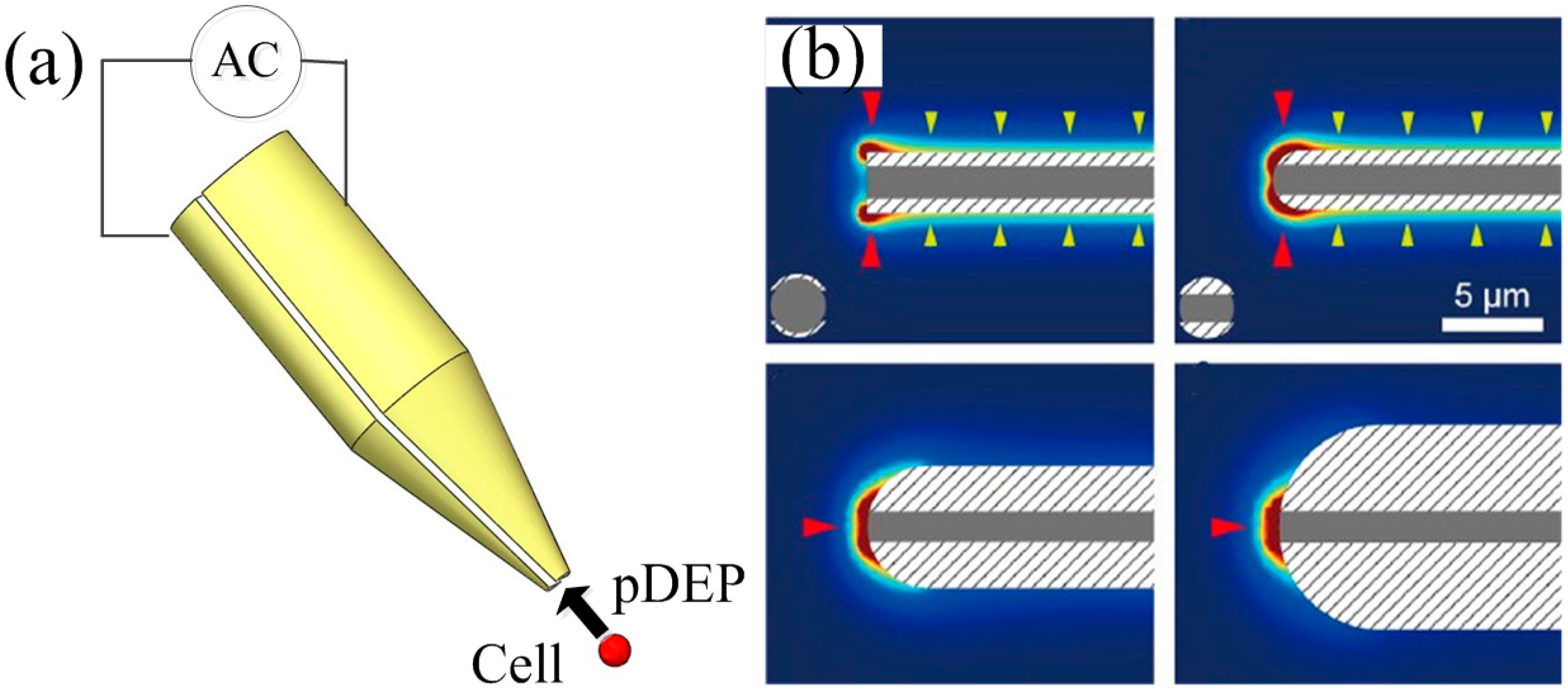
3.1.4. Dielectrophoresis Tweezers
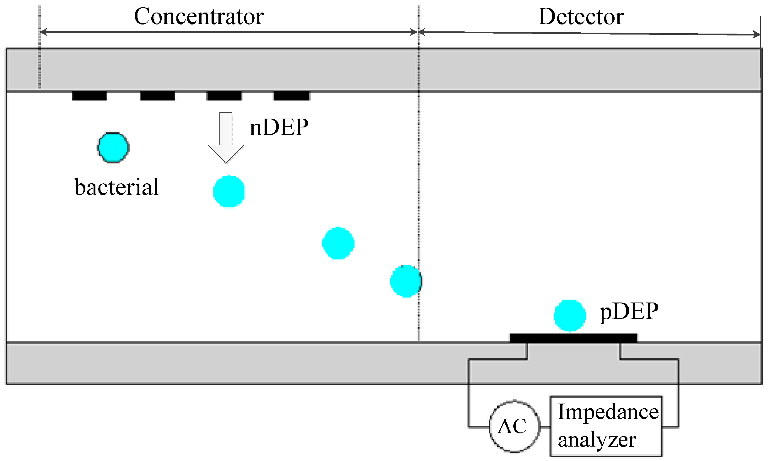
3.2. Detection
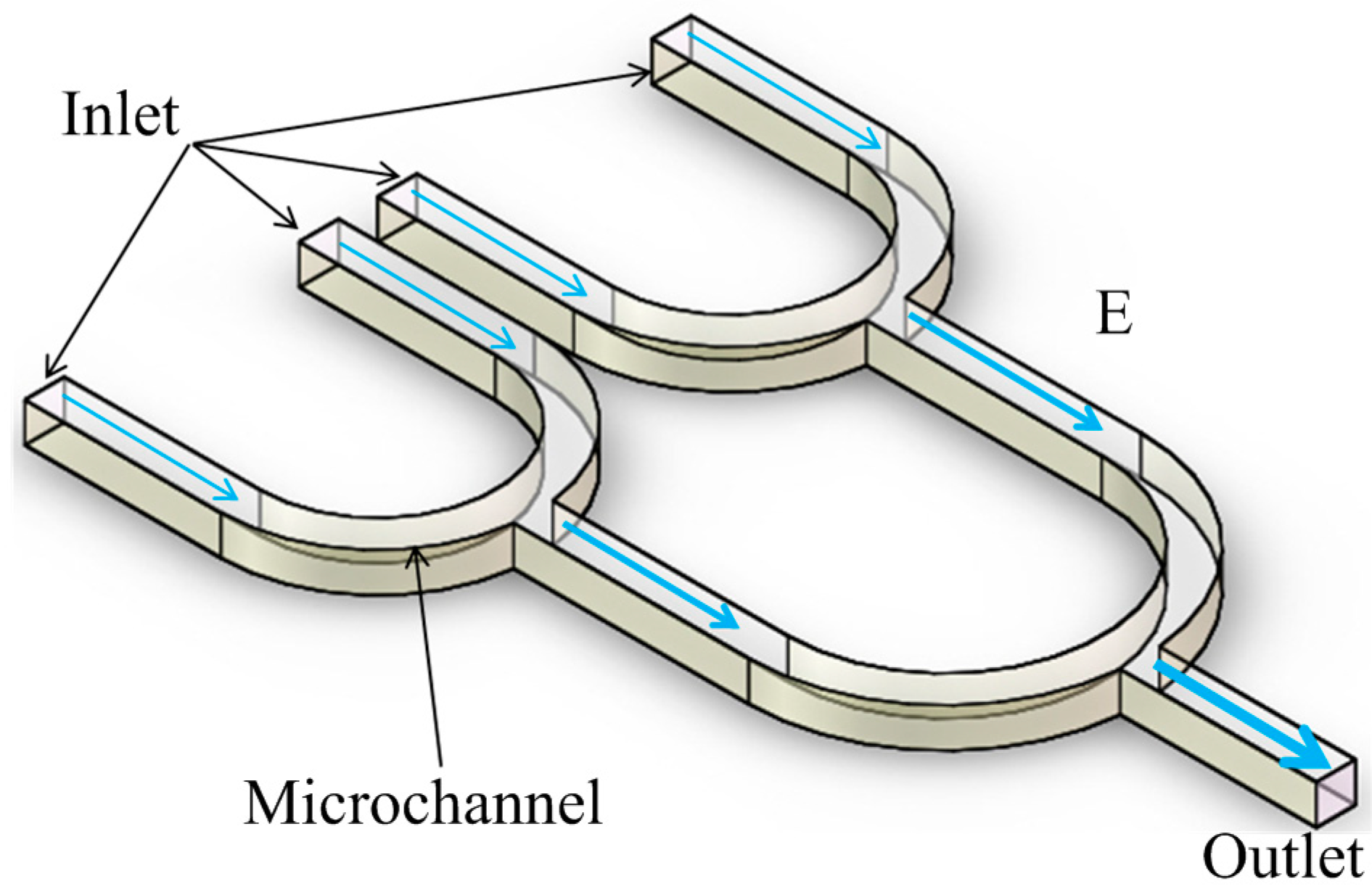
3.3. Focusing
3.4. Pairing

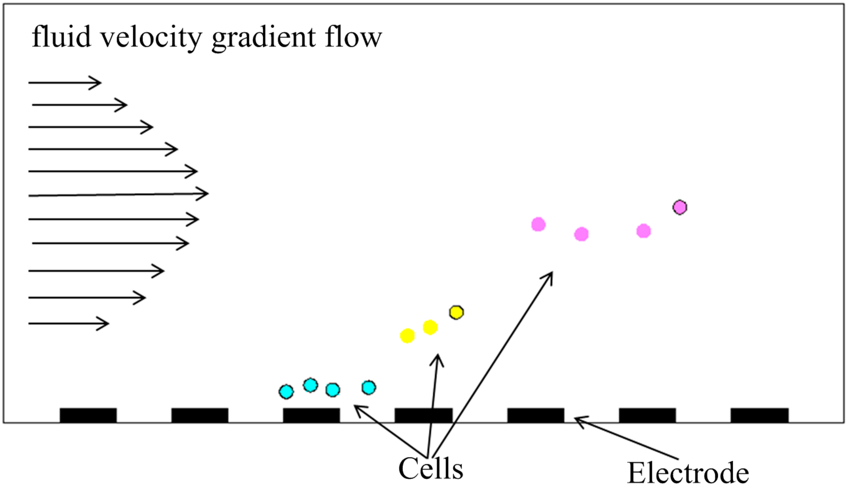
3.5. Separation
3.5.1. Time-Based Separation
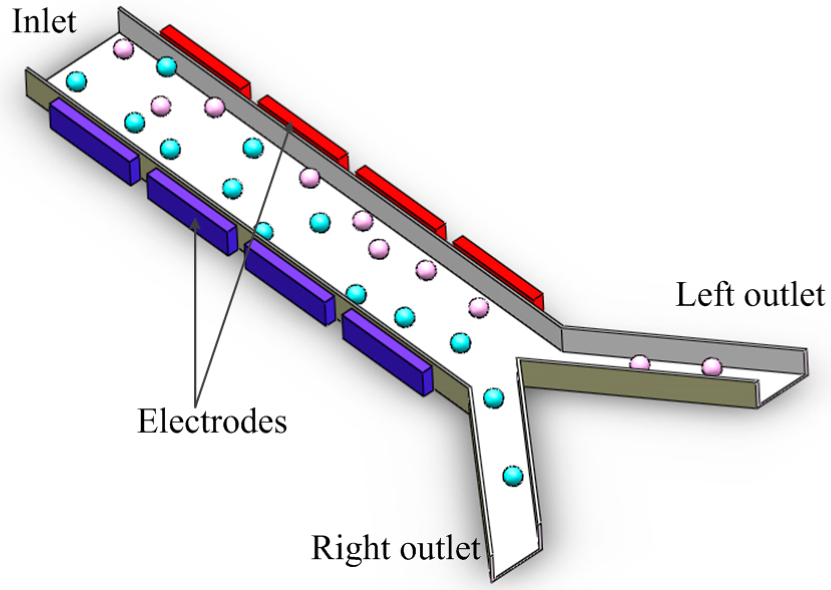
3.5.2. Space-Based Separation

3.5.3. Insulator-Based Separation
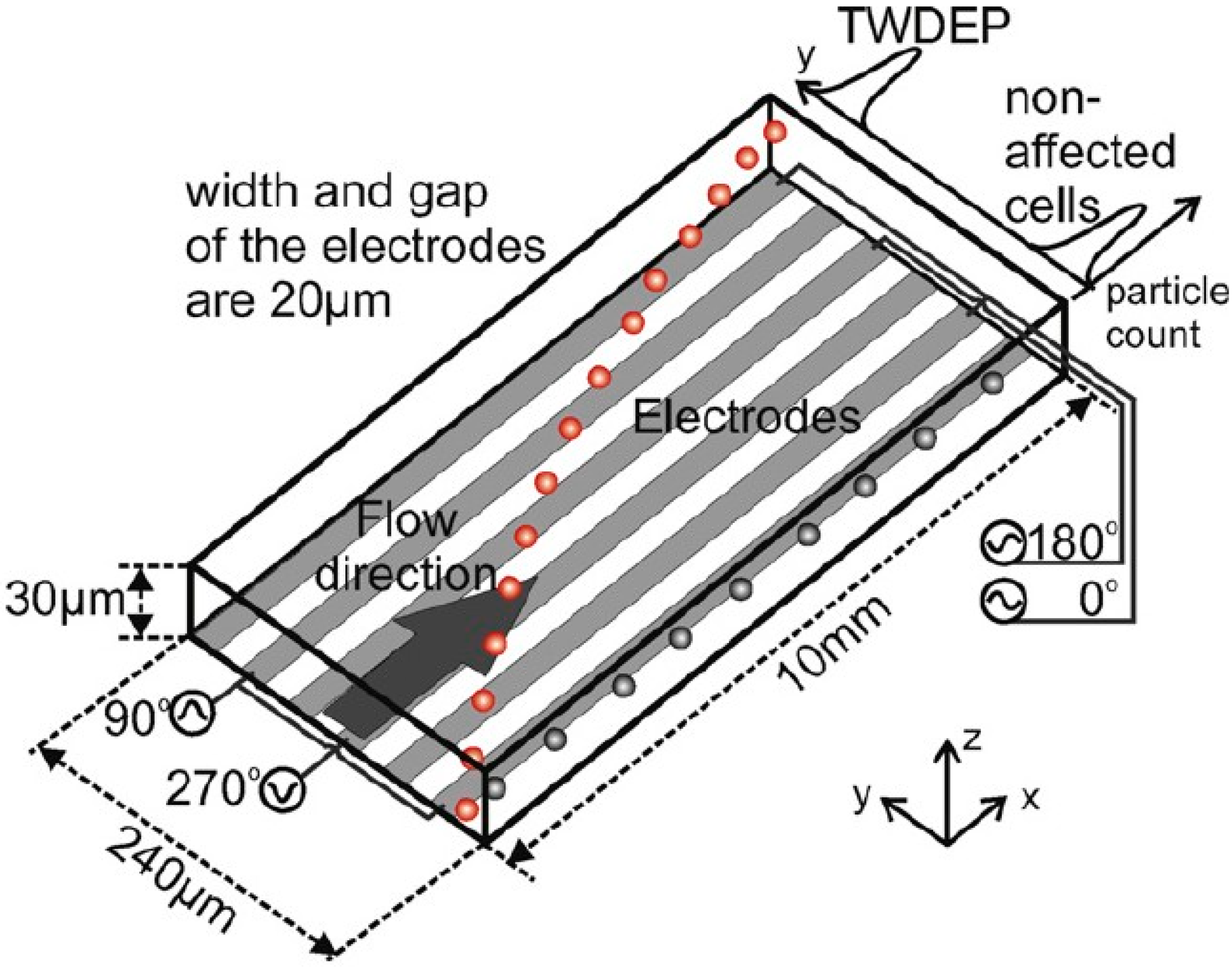
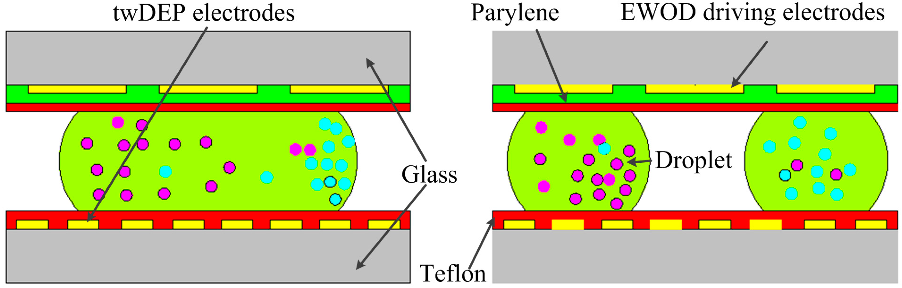
3.5.4. Separation Based on Traveling-Wave Dielectrophoresis
3.5.5. Separation Based on Dual Frequency Dielectrophoresis
3.5.6. Isodielectric Separation
4. The Effect of Dielectrophoresis on Bioparticle Viability
5. Concluding Remarks
Acknowledgments
Conflicts of Interest
References
- Shao, B.; Zlatanovic, S.; Ozkan, M.; Birkbeck, A.L.; Esener, S.C. Manipulation of microspheres and biological cells with multiple agile vcsel traps. Sens. Actuators B 2006, 113, 866–874. [Google Scholar] [CrossRef]
- Huang, S.-B.; Wu, M.-H.; Lin, Y.-H.; Hsieh, C.-H.; Yang, C.-L.; Lin, H.-C.; Tseng, C.-P.; Lee, G.-B. High-purity and label-free isolation of circulating tumor cells (CTCS) in a microfluidic platform by using optically-induced-dielectrophoretic (ODEP) force. Lab. Chip 2013, 13, 1371–1383. [Google Scholar] [CrossRef] [PubMed]
- Tanyeri, M.; Schroeder, C.M. Manipulation and confinement of single particles using fluid flow. Nano Lett. 2013, 13, 2357–2364. [Google Scholar] [CrossRef]
- Lilliehorn, T.; Simu, U.; Nilsson, M.; Almqvist, M.; Stepinski, T.; Laurell, T.; Nilsson, J.; Johansson, S. Trapping of microparticles in the near field of an ultrasonic transducer. Ultrasonics 2005, 43, 293–303. [Google Scholar] [CrossRef] [PubMed]
- Shah, J.; Wilkins, E. Electrochemical biosensors for detection of biological warfare agents. Electroanalysis 2003, 15, 157–167. [Google Scholar] [CrossRef]
- Hsiung, L.-C.; Chiang, C.-L.; Wang, C.-H.; Huang, Y.-H.; Kuo, C.-T.; Cheng, J.-Y.; Lin, C.-H.; Wu, V.; Chou, H.-Y.; Jong, D.-S. Dielectrophoresis-based cellular microarray chip for anticancer drug screening in perfusion microenvironments. Lab. Chip 2011, 11, 2333–2342. [Google Scholar] [CrossRef] [PubMed]
- Laux, E.M.; Kaletta, U.C.; Bier, F.F.; Wenger, C.; Hölzel, R. Functionality of dielectrophoretically immobilized enzyme molecules. Electrophoresis 2014, 35, 459–466. [Google Scholar] [CrossRef] [PubMed]
- Ivanoff, C.S.; Hottel, T.L.; Garcia-Godoy, F. Dielectrophoresis: A model to transport drugs directly into teeth. Electrophoresis 2012, 33, 1311–1321. [Google Scholar] [CrossRef] [PubMed]
- Ermolina, I.; Morgan, H. The electrokinetic properties of latex particles: Comparison of electrophoresis and dielectrophoresis. J. Colloid Interface Sci. 2005, 285, 419–428. [Google Scholar] [CrossRef] [PubMed]
- Zhao, S.; Wang, J.; Ye, F.; Liu, Y.-M. Determination of uric acid in human urine and serum by capillary electrophoresis with chemiluminescence detection. Anal. Biochem. 2008, 378, 127–131. [Google Scholar] [CrossRef] [PubMed]
- Jones, T.B.; Jones, T.B. Electromechanics of Particles; Cambridge University Press: Cambridege, UK, 2005. [Google Scholar]
- Pohl, H.A.; Crane, J.S. Dielectrophoresis of cells. Biophys. J. 1971, 11, 711–727. [Google Scholar] [CrossRef] [PubMed]
- Pohl, H.A.; Crane, J.S. Dielectrophoretic force. J. Theor. Biol. 1972, 37, 1–13. [Google Scholar] [CrossRef] [PubMed]
- Pohl, H.A.; Pohl, H. Dielectrophoresis: The Behavior of Neutral Matter in Nonuniform Electric Fields; Cambridge University Press: Cambridge, UK, 1978. [Google Scholar]
- Verpoorte, E.; de Rooij, N.F. Microfluidics meets MEMS. Proc. IEEE 2003, 91, 930–953. [Google Scholar] [CrossRef]
- Sebastian, A.; Buckle, A.M.; Markx, G.H. Tissue engineering with electric fields: Immobilization of mammalian cells in multilayer aggregates using dielectrophoresis. Biotechnol. Bioeng. 2007, 98, 694–700. [Google Scholar] [CrossRef] [PubMed]
- Braff, W.A.; Willner, D.; Hugenholtz, P.; Rabaey, K.; Buie, C.R. Dielectrophoresis-based discrimination of bacteria at the strain level based on their surface properties. PLoS One 2013, 8, e76751. [Google Scholar] [CrossRef] [Green Version]
- Arnold, W.; Zimmermann, U. Electro-rotation: Development of a technique for dielectric measurements on individual cells and particles. J. Electrost. 1988, 21, 151–191. [Google Scholar] [CrossRef]
- Huang, Y.; Wang, X.-B.; Tame, J.; Pethig, R. Electrokinetic behaviour of colloidal particles in travelling electric fields: Studies using yeast cells. J. Phys. D 1993, 26, 1528. [Google Scholar]
- Cen, E.G.; Dalton, C.; Li, Y.; Adamia, S.; Pilarski, L.M.; Kaler, K.V. A combined dielectrophoresis, traveling wave dielectrophoresis and electrorotation microchip for the manipulation and characterization of human malignant cells. J. Microbiol. Methods 2004, 58, 387–401. [Google Scholar] [CrossRef] [PubMed]
- Wang, X.-B.; Huang, Y.; Becker, F.; Gascoyne, P. A unified theory of dielectrophoresis and travelling wave dielectrophoresis. J. Phys. D 1994, 27, 1571. [Google Scholar]
- Irimajiri, A.; Hanai, T.; Inouye, A. A dielectric theory of “multi-stratified shell” model with its application to a lymphoma cell. J. Theor. Biol. 1979, 78, 251–269. [Google Scholar] [CrossRef] [PubMed]
- Huang, Y.; Holzel, R.; Pethig, R.; Wang, X.-B. Differences in the AC electrodynamics of viable and non-viable yeast cells determined through combined dielectrophoresis and electrorotation studies. Phys. Med. Biol. 1992, 37, 1499. [Google Scholar] [CrossRef]
- Yang, C.; Lei, U. Quasistatic force and torque on ellipsoidal particles under generalized dielectrophoresis. J. Appl. Phys. 2007, 102, 094702. [Google Scholar]
- Arai, F.; Maruyama, H.; Sakami, T.; Ichikawa, A.; Kouketsu, N.; Dong, L.; Fukuda, T. In pinpoint injection of micro tools using dielectrophoresis and hydrophobic surface for minimally invasive separation of microbe. In Proceedings of the the Fifteenth IEEE International Conference on Micro Electro Mechanical Systems, Las Vegas, NV, USA, 24 January 2002; pp. 48–51.
- Clow, A.L.; Gaynor, P.T.; Oback, B.J. A novel micropit device integrates automated cell positioning by dielectrophoresis and nuclear transfer by electrofusion. Biomed. Microdevices 2010, 12, 777–786. [Google Scholar] [CrossRef] [PubMed]
- MacQueen, L.A.; Buschmann, M.D.; Wertheimer, M.R. Gene delivery by electroporation after dielectrophoretic positioning of cells in a non-uniform electric field. Bioelectrochemistry 2008, 72, 141–148. [Google Scholar] [CrossRef] [PubMed]
- Tseng, H.-Y.; Huang, Y.-H.; Huang, H.-Y.; Yao, D.-J. In oviduct-mimetic chip for sperm separation and oocyte manipulation to enhance the probability of fertilization for oligozoospermia patient. In Proceedings of the 2013 8th IEEE International Conference on Nano/Micro Engineered and Molecular Systems (NEMS), Suzhou, China, 7–10 April 2013; pp. 602–605.
- Tuukkanen, S.; Kuzyk, A.; Toppari, J.; Hytönen, V.; Ihalainen, T.; Törmä, P. Dielectrophoresis of nanoscale double-stranded DNA and humidity effects on its electrical conductivity. Appl. Phys. Lett. 2005, 87, 183102. [Google Scholar] [CrossRef]
- Srivastava, S.K.; Daggolu, P.R.; Burgess, S.C.; Minerick, A.R. Dielectrophoretic characterization of erythrocytes: Positive abo blood types. Electrophoresis 2008, 29, 5033–5046. [Google Scholar] [CrossRef] [PubMed]
- Ramón-Azcón, J.; Yasukawa, T.; Mizutani, F. Sensitive and spatially multiplexed detection system based on dielectrophoretic manipulation of DNA-encoded particles used as immunoreactions platform. Anal. Chem. 2010, 83, 1053–1060. [Google Scholar] [CrossRef]
- Lee, H.J.; Lee, S.H.; Yasukawa, T.; Ramón-Azcón, J.; Mizutani, F.; Ino, K.; Shiku, H.; Matsue, T. Rapid and simple immunosensing system for simultaneous detection of tumor markers based on negative-dielectrophoretic manipulation of microparticles. Talanta 2010, 81, 657–663. [Google Scholar] [CrossRef]
- Chuang, C.-H.; Ju, J.-W.; Huang, Y.-W. Enhancing fluorescent response of immunosensing by a dielectrophoresis chip with transparent electrodes and microcavities array. Micro Nano Lett. 2013, 8, 659–663. [Google Scholar] [CrossRef]
- Gascoyne, P.R.; Vykoukal, J.V. Dielectrophoresis-based sample handling in general-purpose programmable diagnostic instruments. Proc. IEEE 2004, 92, 22–42. [Google Scholar] [CrossRef]
- Vykoukal, J.; Vykoukal, D.M.; Freyberg, S.; Alt, E.U.; Gascoyne, P.R. Enrichment of putative stem cells from adipose tissue using dielectrophoretic field-flow fractionation. Lab. Chip 2008, 8, 1386–1393. [Google Scholar] [CrossRef] [PubMed]
- Voldman, J. A Microfabricated Dielectrophoretic Trapping Array for Cell-Based Biological Assays. Ph.D. Thesis, Massachusetts Institute of Technology, Cambridge, MA, USA, June 2001. [Google Scholar]
- Johari, J.; Hübner, Y.; Hull, J.C.; Dale, J.W.; Hughes, M.P. Dielectrophoretic assay of bacterial resistance to antibiotics. Phys. Med. Biol. 2003, 48, N193. [Google Scholar] [CrossRef]
- Chugh, D.; Kaler, K.V.I.S. Integrated liquid and droplet dielectrophoresis for biochemical assays. Microfluidics Nanofluidics 2010, 8, 445–456. [Google Scholar] [CrossRef]
- Kato, M.; Sasamori, E.; Chiba, T.; Hanyu, Y. Cell activation by CPG ODN leads to improved electrofusion in hybridoma production. J. Immunol. Methods 2011, 373, 102–110. [Google Scholar] [CrossRef] [PubMed]
- Tan, C.; Dannull, J.; Nair, S.K.; Ding, E.; Tyler, D.S.; Pruitt, S.K.; Lee, W.T. Local secretion of IL-12 augments the therapeutic impact of dendritic cell–tumor cell fusion vaccination. J. Surg. Res. 2013, 185, 904–911. [Google Scholar] [CrossRef] [PubMed]
- Cavallaro, D.; Capaccioli, S.; Carloni, V. 147 targeting mechanism of cell fusion as a novel approach to abrogate multi-drug resistance of metastatic colon cancer. Eur. J. Cancer 2012, 48, 45. [Google Scholar] [CrossRef]
- Yang, W.J.; Li, S.H.; Weisel, R.D.; Liu, S.M.; Li, R.K. Cell fusion contributes to the rescue of apoptotic cardiomyocytes by bone marrow cells. J. Cell. Mol. Med. 2012, 16, 3085–3095. [Google Scholar] [CrossRef] [PubMed]
- Regtmeier, J.; Duong, T.T.; Eichhorn, R.; Anselmetti, D.; Ros, A. Dielectrophoretic manipulation of DNA: Separation and polarizability. Anal. Chem. 2007, 79, 3925–3932. [Google Scholar] [CrossRef] [PubMed]
- Huang, Y.; Joo, S.; Duhon, M.; Heller, M.; Wallace, B.; Xu, X. Dielectrophoretic cell separation and gene expression profiling on microelectronic chip arrays. Anal. Chem. 2002, 74, 3362–3371. [Google Scholar] [CrossRef] [PubMed]
- Sonnenberg, A.; Marciniak, J.Y.; Skowronski, E.A.; Manouchehri, S.; Rassenti, L.; Ghia, E.M.; Widhopf, G.F.; Kipps, T.J.; Heller, M.J. Dielectrophoretic isolation and detection of cancer-related circulating cell-free DNA biomarkers from blood and plasma. Electrophoresis 2014, 35, 1828–1836. [Google Scholar] [CrossRef] [PubMed]
- Hu, X.; Bessette, P.H.; Qian, J.; Meinhart, C.D.; Daugherty, P.S.; Soh, H.T. Marker-specific sorting of rare cells using dielectrophoresis. Proc. Natl. Acad. Sci. USA 2005, 102, 15757–15761. [Google Scholar] [CrossRef] [PubMed]
- Fu, A.Y.; Chou, H.-P.; Spence, C.; Arnold, F.H.; Quake, S.R. An integrated microfabricated cell sorter. Anal. Chem. 2002, 74, 2451–2457. [Google Scholar] [CrossRef] [PubMed]
- Moon, H.-S.; Kwon, K.; Kim, S.-I.; Han, H.; Sohn, J.; Lee, S.; Jung, H.-I. Continuous separation of breast cancer cells from blood samples using multi-orifice flow fractionation (MOFF) and dielectrophoresis (DEP). Lab. Chip 2011, 11, 1118–1125. [Google Scholar] [CrossRef] [PubMed]
- Mohamad, A.; Jeynes, J.; Hughes, M. Dielectrophoretic response of DNA shows different conduction mechanisms for poly (dg)-poly (dc) and poly (da)-poly (dt) in solution. NanoBiosci. IEEE Trans. 2014, 13, 51–54. [Google Scholar] [CrossRef]
- Liang, X.; Graham, K.; Johannessen, A.; Costea, D.; Labeed, F. Human oral cancer cells with increasing tumorigenic abilities exhibit higher effective membrane capacitance. Integr. Biol. 2014, 6, 545–554. [Google Scholar] [CrossRef]
- Hölzel, R.; Calander, N.; Chiragwandi, Z.; Willander, M.; Bier, F.F. Trapping single molecules by dielectrophoresis. Phys. Rev. Lett. 2005, 95, 128102. [Google Scholar] [CrossRef]
- Kumemura, M.; Collard, D.; Sakaki, N.; Yamahata, C.; Hosogi, M.; Hashiguchi, G.; Fujita, H. Single-DNA-molecule trapping with silicon nanotweezers using pulsed dielectrophoresis. J. Micromech. Microeng. 2011, 21, 054020. [Google Scholar] [CrossRef]
- Chou, C.-F.; Tegenfeldt, J.O.; Bakajin, O.; Chan, S.S.; Cox, E.C.; Darnton, N.; Duke, T.; Austin, R.H. Electrodeless dielectrophoresis of single-and double-stranded DNA. Biophys. J. 2002, 83, 2170–2179. [Google Scholar] [CrossRef] [PubMed]
- Lapizco-Encinas, B.H.; Ozuna-Chacón, S.; Rito-Palomares, M. Protein manipulation with insulator-based dielectrophoresis and direct current electric fields. J. Chromatogr. A 2008, 1206, 45–51. [Google Scholar] [CrossRef] [PubMed]
- Thwar, P.K.; Linderman, J.J.; Burns, M.A. Electrodeless direct current dielectrophoresis using reconfigurable field-shaping oil barriers. Electrophoresis 2007, 28, 4572–4581. [Google Scholar] [CrossRef] [PubMed]
- Shafiee, H.; Caldwell, J.L.; Sano, M.B.; Davalos, R.V. Contactless dielectrophoresis: A new technique for cell manipulation. Biomed. Microdevices 2009, 11, 997–1006. [Google Scholar] [CrossRef] [PubMed]
- Jen, C.-P.; Chen, T.-W. Trapping of cells by insulator-based dielectrophoresis using open-top microstructures. Microsyst. Technol. 2009, 15, 1141–1148. [Google Scholar] [CrossRef]
- Jen, C.-P.; Chen, T.-W. Selective trapping of live and dead mammalian cells using insulator-based dielectrophoresis within open-top microstructures. Biomed. Microdevices 2009, 11, 597–607. [Google Scholar] [CrossRef] [PubMed]
- Jang, L.-S.; Huang, P.-H.; Lan, K.-C. Single-cell trapping utilizing negative dielectrophoretic quadrupole and microwell electrodes. Biosens. Bioelectron. 2009, 24, 3637–3644. [Google Scholar] [CrossRef] [PubMed]
- Lan, K.-C.; Jang, L.-S. Integration of single-cell trapping and impedance measurement utilizing microwell electrodes. Biosens. Bioelectron. 2011, 26, 2025–2031. [Google Scholar] [CrossRef] [PubMed]
- Wang, C.-C.; Lan, K.-C.; Chen, M.-K.; Wang, M.-H.; Jang, L.-S. Adjustable trapping position for single cells using voltage phase-controlled method. Biosens. Bioelectron. 2013, 49, 297–304. [Google Scholar] [CrossRef] [PubMed]
- Hunt, T.; Westervelt, R. Dielectrophoresis tweezers for single cell manipulation. Biomed. Microdevices 2006, 8, 227–230. [Google Scholar] [CrossRef] [PubMed]
- Kodama, T.; Osaki, T.; Kawano, R.; Kamiya, K.; Miki, N.; Takeuchi, S. Round-tip dielectrophoresis-based tweezers for single micro-object manipulation. Biosens. Bioelectron. 2013, 47, 206–212. [Google Scholar] [CrossRef] [PubMed]
- Higginbotham, S.N.; Sweatman, D.R. A combined travelling wave dielectrophoresis and impedance sensing device for sensing biological cell suspensions. J. Phys. D 2008, 41, 175503. [Google Scholar] [CrossRef]
- Hirota, K.; Inagaki, S.; Hamada, R.; Ishihara, K.; Miyake, Y. Evaluation of a rapid oral bacteria quantification system using dielectrophoresis and the impedance measurement. Biocontrol Sci. 2014, 19, 45–49. [Google Scholar] [CrossRef] [PubMed]
- Moon, H.-S.; Im, H.T.; Choi, A.; Jung, H.-I. Real-time detection of food-borne bacterial adenosine triphosphate (ATP) using dielectrophoretic force and a bioluminescence sensor. Microchim. Acta 2010, 170, 283–288. [Google Scholar] [CrossRef]
- Yang, L. Dielectrophoresis assisted immuno-capture and detection of foodborne pathogenic bacteria in biochips. Talanta 2009, 80, 551–558. [Google Scholar] [CrossRef] [PubMed]
- Menachery, A.; Kremer, C.; Wong, P.E.; Carlsson, A.; Neale, S.L.; Barrett, M.P.; Cooper, J.M. Counterflow dielectrophoresis for trypanosome enrichment and detection in blood. Sci. Rep. 2012, 2, 775. [Google Scholar] [CrossRef]
- Hamada, R.; Takayama, H.; Shonishi, Y.; Mao, L.; Nakano, M.; Suehiro, J. A rapid bacteria detection technique utilizing impedance measurement combined with positive and negative dielectrophoresis. Sens. Actuators B 2013, 181, 439–445. [Google Scholar] [CrossRef]
- Li, S.; Cui, H.; Yuan, Q.; Wu, J.; Wadhwa, A.; Eda, S.; Jiang, H. AC electrokinetics-enhanced capacitive immunosensor for point-of-care serodiagnosis of infectious diseases. Biosens. Bioelectron. 2014, 51, 437–443. [Google Scholar] [CrossRef] [PubMed]
- Baek, S.H.; Chang, W.-J.; Baek, J.-Y.; Yoon, D.S.; Bashir, R.; Lee, S.W. Dielectrophoretic technique for measurement of chemical and biological interactions. Anal. Chem. 2009, 81, 7737–7742. [Google Scholar] [CrossRef] [PubMed]
- Park, I.S.; Eom, K.; Son, J.; Chang, W.-J.; Park, K.; Kwon, T.; Yoon, D.S.; Bashir, R.; Lee, S.W. Microfluidic multifunctional probe array dielectrophoretic force spectroscopy with wide loading rates. ACS Nano 2012, 6, 8665–8673. [Google Scholar] [CrossRef] [PubMed]
- Huang, C.; Liu, H.; Bander, N.H.; Kirby, B.J. Enrichment of prostate cancer cells from blood cells with a hybrid dielectrophoresis and immunocapture microfluidic system. Biomed. Microdevices 2013, 15, 941–948. [Google Scholar] [CrossRef] [PubMed]
- Huang, C.-T.; Amstislavskaya, T.G.; Chen, G.-H.; Chang, H.-H.; Chen, Y.-H.; Jen, C.-P. Selectively concentrating cervical carcinoma cells from red blood cells utilizing dielectrophoresis with circular ito electrodes in stepping electric fields. J. Med. Biol. Eng. 2013, 33, 51–58. [Google Scholar] [CrossRef]
- Chen, D.; Du, H.; Tay, C.Y. Rapid concentration of nanoparticles with DC dielectrophoresis in focused electric fields. Nanoscale Res. Lett. 2010, 5, 55–60. [Google Scholar] [CrossRef]
- Chen, D.; Du, H. A microfluidic device for rapid concentration of particles in continuous flow by DC dielectrophoresis. Microfluidics Nanofluidics 2010, 9, 281–291. [Google Scholar] [CrossRef]
- Cho, Y.K.; Kim, S.; Lee, K.; Park, C.; Lee, J.G.; Ko, C. Bacteria concentration using a membrane type insulator-based dielectrophoresis in a plastic chip. Electrophoresis 2009, 30, 3153–3159. [Google Scholar] [CrossRef] [PubMed]
- Gallo-Villanueva, R.C.; Rodríguez-López, C.E.; Díaz-de-la-Garza, R.I.; Reyes-Betanzo, C.; Lapizco-Encinas, B.H. DNA manipulation by means of insulator-based dielectrophoresis employing direct current electric fields. Electrophoresis 2009, 30, 4195–4205. [Google Scholar] [CrossRef] [PubMed]
- Lewpiriyawong, N.; Yang, C.; Lam, Y.C. Dielectrophoretic manipulation of particles in a modified microfluidic h filter with multi-insulating blocks. Biomicrofluidics 2008, 2, 034105. [Google Scholar] [CrossRef]
- Zhu, J.; Xuan, X. Dielectrophoretic focusing of particles in a microchannel constriction using dc-biased AC flectric fields. Electrophoresis 2009, 30, 2668–2675. [Google Scholar] [CrossRef] [PubMed]
- Lewpiriyawong, N.; Yang, C.; Lam, Y.C. Electrokinetically driven concentration of particles and cells by dielectrophoresis with dc-offset AC electric field. Microfluidics Nanofluidics 2012, 12, 723–733. [Google Scholar] [CrossRef]
- Hu, N.; Yang, J.; Yin, Z.Q.; Ai, Y.; Qian, S.; Svir, I.B.; Xia, B.; Yan, J.W.; Hou, W.S.; Zheng, X.L. A high-throughput dielectrophoresis-based cell electrofusion microfluidic device. Electrophoresis 2011, 32, 2488–2495. [Google Scholar] [CrossRef] [PubMed]
- Hu, N.; Yang, J.; Qian, S.; Joo, S.W.; Zheng, X. A cell electrofusion microfluidic device integrated with 3D thin-film microelectrode arrays. Biomicrofluidics 2011, 5, 034121. [Google Scholar]
- Tresset, G.; Takeuchi, S. A microfluidic device for electrofusion of biological vesicles. Biomed. Microdevices 2004, 6, 213–218. [Google Scholar] [CrossRef] [PubMed]
- Gel, M.; Suzuki, S.; Kimura, Y.; Kurosawa, O.; Techaumnat, B.; Oana, H.; Washizu, M. Microorifice-based high-yield cell fusion on microfluidic chip: Electrofusion of selected pairs and fusant viability. NanoBiosci. IEEE Trans. 2009, 8, 300–305. [Google Scholar] [CrossRef]
- Kimura, Y.; Gel, M.; Techaumnat, B.; Oana, H.; Kotera, H.; Washizu, M. Dielectrophoresis-assisted massively parallel cell pairing and fusion based on field constriction created by a micro-orifice array sheet. Electrophoresis 2011, 32, 2496–2501. [Google Scholar] [CrossRef] [PubMed]
- Şen, M.; Ino, K.; Ramón-Azcón, J.; Shiku, H.; Matsue, T. Cell pairing using a dielectrophoresis-based device with interdigitated array electrodes. Lab. Chip 2013, 13, 3650–3652. [Google Scholar] [CrossRef] [PubMed]
- Elitas, M.; Martinez-Duarte, R.; Dhar, N.; McKinney, J.D.; Renaud, P. Dielectrophoresis-based purification of antibiotic-treated bacterial subpopulations. Lab. Chip 2014, 14, 1850–1857. [Google Scholar] [CrossRef] [PubMed]
- Chen, C.-C.; Lin, P.-H.; Chung, C.-K. Microfluidic chip for plasma separation from undiluted human whole blood samples using low voltage contactless dielectrophoresis and capillary force. Lab. Chip 2014, 14, 1996–2001. [Google Scholar] [CrossRef] [PubMed]
- Voldman, J.; Braff, R.A.; Toner, M.; Gray, M.L.; Schmidt, M.A. Holding forces of single-particle dielectrophoretic traps. Biophys. J. 2001, 80, 531–542. [Google Scholar] [CrossRef] [PubMed]
- Li, H.; Zheng, Y.; Akin, D.; Bashir, R. Characterization and modeling of a microfluidic dielectrophoresis filter for biological species. Microelectromech. Syst. J. 2005, 14, 103–112. [Google Scholar] [CrossRef]
- Morgan, H.; Hughes, M.P.; Green, N.G. Separation of submicron bioparticles by dielectrophoresis. Biophys. J. 1999, 77, 516–525. [Google Scholar] [CrossRef] [PubMed]
- Gascoyne, P.; Mahidol, C.; Ruchirawat, M.; Satayavivad, J.; Watcharasit, P.; Becker, F.F. Microsample preparation by dielectrophoresis: Isolation of malaria. Lab. Chip 2002, 2, 70–75. [Google Scholar] [CrossRef] [PubMed]
- Li, H.; Bashir, R. Dielectrophoretic separation and manipulation of live and heat-treated cells of listeria on microfabricated devices with interdigitated electrodes. Sens. Actuators B 2002, 86, 215–221. [Google Scholar] [CrossRef]
- Arnold, W.M. Positioning and levitation media for the separation of biological cells. Ind. Appl. IEEE Trans. 2001, 37, 1468–1475. [Google Scholar] [CrossRef]
- Choi, W.; Kim, J.-S.; Lee, D.-H.; Lee, K.-K.; Koo, D.-B.; Park, J.-K. Dielectrophoretic oocyte selection chip for in vitro fertilization. Biomed. Microdevices 2008, 10, 337–345. [Google Scholar] [CrossRef] [PubMed]
- Yu, L.; Iliescu, C.; Xu, G.; Tay, F.E. Sequential field-flow cell separation method in a dielectrophoretic chip with 3-d electrodes. Microelectromech. Syst. J. 2007, 16, 1120–1129. [Google Scholar] [CrossRef]
- Cemazar, J.; Vrtacnik, D.; Amon, S.; Kotnik, T. Dielectrophoretic field-flow microchamber for separation of biological cells based on their electrical properties. NanoBiosci. IEEE Trans. 2011, 10, 36–43. [Google Scholar] [CrossRef]
- Gascoyne, P.R.; Noshari, J.; Anderson, T.J.; Becker, F.F. Isolation of rare cells from cell mixtures by dielectrophoresis. Electrophoresis 2009, 30, 1388–1398. [Google Scholar] [CrossRef] [PubMed]
- Piacentini, N.; Mernier, G.; Tornay, R.; Renaud, P. Separation of platelets from other blood cells in continuous-flow by dielectrophoresis field-flow-fractionation. Biomicrofluidics 2011, 5, 034122. [Google Scholar] [CrossRef]
- Lee, J.; Kim, Y.; Beebe, D.J.; Kim, B. Harnessing gravitational, hydrodynamic and negative dielectrophoretic forces for higher throughput cell sorting. BioChip J. 2012, 6, 229–239. [Google Scholar] [CrossRef]
- Kralj, J.G.; Lis, M.T.; Schmidt, M.A.; Jensen, K.F. Continuous dielectrophoretic size-based particle sorting. Anal. Chem. 2006, 78, 5019–5025. [Google Scholar] [CrossRef] [PubMed]
- Han, K.-H.; Han, S.-I.; Frazier, A.B. Lateral displacement as a function of particle size using a piecewise curved planar interdigitated electrode array. Lab. Chip 2009, 9, 2958–2964. [Google Scholar] [CrossRef] [PubMed]
- Kim, U.; Qian, J.; Kenrick, S.A.; Daugherty, P.S.; Soh, H.T. Multitarget dielectrophoresis activated cell sorter. Anal. Chem. 2008, 80, 8656–8661. [Google Scholar] [CrossRef] [PubMed]
- Han, S.-I.; Lee, S.-M.; Joo, Y.-D.; Han, K.-H. Lateral dielectrophoretic microseparators to measure the size distribution of blood cells. Lab. Chip 2011, 11, 3864–3872. [Google Scholar] [CrossRef] [PubMed]
- Lapizco-Encinas, B.H.; Simmons, B.A.; Cummings, E.B.; Fintschenko, Y. Insulator-based dielectrophoresis for the selective concentration and separation of live bacteria in water. Electrophoresis 2004, 25, 1695–1704. [Google Scholar] [CrossRef] [PubMed]
- Lapizco-Encinas, B.H.; Simmons, B.A.; Cummings, E.B.; Fintschenko, Y. Dielectrophoretic concentration and separation of live and dead bacteria in an array of insulators. Anal. Chem. 2004, 76, 1571–1579. [Google Scholar] [CrossRef] [PubMed]
- Jen, C.-P.; Huang, C.-T.; Shih, H.-Y. Hydrodynamic separation of cells utilizing insulator-based dielectrophoresis. Microsyst. Technol. 2010, 16, 1097–1104. [Google Scholar] [CrossRef]
- Kang, K.H.; Kang, Y.; Xuan, X.; Li, D. Continuous separation of microparticles by size with direct current-dielectrophoresis. Electrophoresis 2006, 27, 694–702. [Google Scholar] [CrossRef] [PubMed]
- Kang, Y.; Li, D.; Kalams, S.A.; Eid, J.E. Dc-dielectrophoretic separation of biological cells by size. Biomed. Microdevices 2008, 10, 243–249. [Google Scholar] [CrossRef] [PubMed]
- Zhang, L.; Tatar, F.; Turmezei, P.; Bastemeijer, J.; Mollinger, J.; Piciu, O.; Bossche, A. Continuous electrodeless dielectrophoretic separation in a circular channel. J. Phys. 2006, 34, 527. [Google Scholar]
- Viefhues, M.; Eichhorn, R.; Fredrich, E.; Regtmeier, J.; Anselmetti, D. Continuous and reversible mixing or demixing of nanoparticles by dielectrophoresis. Lab. Chip 2012, 12, 485–494. [Google Scholar] [CrossRef] [PubMed]
- Viefhues, M.; Regtmeier, J.; Anselmetti, D. Fast and continuous-flow separation of DNA-complexes and topological DNA variants in microfluidic chip format. Analyst 2013, 138, 186–196. [Google Scholar] [CrossRef] [PubMed]
- Viefhues, M.; Wegener, S.; Rischmüller, A.; Schleef, M.; Anselmetti, D. Dielectrophoresis based continuous-flow nano sorter: Fast quality control of gene vaccines. Lab. Chip 2013, 13, 3111–3118. [Google Scholar] [CrossRef] [PubMed]
- Lei, U.; Huang, C.; Chen, J.; Yang, C.; Lo, Y.; Wo, A.; Chen, C.; Fung, T. A travelling wave dielectrophoretic pump for blood delivery. Lab. Chip 2009, 9, 1349–1356. [Google Scholar] [CrossRef] [PubMed]
- Van den Driesche, S.; Rao, V.; Puchberger-Enengl, D.; Witarski, W.; Vellekoop, M.J. Continuous cell from cell separation by traveling wave dielectrophoresis. Sens. Actuators B 2012, 170, 207–214. [Google Scholar] [CrossRef]
- Cheng, I.-F.; Froude, V.E.; Zhu, Y.; Chang, H.-C.; Chang, H.-C. A continuous high-throughput bioparticle sorter based on 3d traveling-wave dielectrophoresis. Lab. Chip 2009, 9, 3193–3201. [Google Scholar] [CrossRef] [PubMed]
- Choi, E.; Kim, B.; Park, J. High-throughput microparticle separation using gradient traveling wave dielectrophoresis. J. Micromech. Microeng. 2009, 19, 125014. [Google Scholar]
- Zhao, Y.; Yi, U.-C.; Cho, S.K. Microparticle concentration and separation by traveling-wave dielectrophoresis (twDEP) for digital microfluidics. Microelectromech. Syst. J. 2007, 16, 1472–1481. [Google Scholar] [CrossRef]
- Zhao, Y.; Yi, U.-C.; Cho, S.K. In Highly efficient in-droplet particle concentration and separation by twDEP and EWOD for digital microfluidics. In Proceedings of IEEE 20th International Conference on MEMS, Bangkok, Thailand, 10–13 December 2007; pp. 537–540.
- Wang, L.; Lu, J.; Marchenko, S.A.; Monuki, E.S.; Flanagan, L.A.; Lee, A.P. Dual frequency dielectrophoresis with interdigitated sidewall electrodes for microfluidic flow-through separation of beads and cells. Electrophoresis 2009, 30, 782–791. [Google Scholar] [CrossRef] [PubMed]
- Vahey, M.; Voldman, J. An equilibrium method for continuous-flow cell sorting using dielectrophoresis. Anal. Chem. 2008, 80, 3135–3143. [Google Scholar] [CrossRef] [PubMed]
- Markx, G.H.; Carney, L.; Littlefair, M.; Sebastian, A.; Buckle, A.-M. Recreating the hematon: Microfabrication of artificial haematopoietic stem cell microniches in vitro using dielectrophoresis. Biomed. Microdevices 2009, 11, 143–150. [Google Scholar] [CrossRef] [PubMed]
- Gray, D.S.; Tan, J.L.; Voldman, J.; Chen, C.S. Dielectrophoretic registration of living cells to a microelectrode array. Biosens. Bioelectron. 2004, 19, 771–780. [Google Scholar] [CrossRef] [PubMed]
- Hakoda, M.; Hirota, Y. Correlation between dielectric property by dielectrophoretic levitation and growth activity of cells exposed to electric field. Bioprocess. Biosyst. Eng. 2013, 36, 1219–1227. [Google Scholar] [CrossRef] [PubMed]
- Park, K.; Suk, H.-J.; Akin, D.; Bashir, R. Dielectrophoresis-based cell manipulation using electrodes on a reusable printed circuit board. Lab. Chip 2009, 9, 2224–2229. [Google Scholar] [CrossRef] [PubMed]
- Donato, S.S.; Chu, V.; Prazeres, D.M.; Conde, J.P. Metabolic viability of Escherichia coli trapped by dielectrophoresis in microfluidics. Electrophoresis 2013, 34, 575–582. [Google Scholar] [CrossRef] [PubMed]
- Jaeger, M.; Mueller, T.; Schnelle, T. Thermometry in dielectrophoresis chips for contact-free cell handling. J. Phys. D 2007, 40, 95. [Google Scholar] [CrossRef]
- Li, M.; Li, S.; Cao, W.; Li, W.; Wen, W.; Alici, G. Improved concentration and separation of particles in a 3D dielectrophoretic chip integrating focusing, aligning and trapping. Microfluidics Nanofluidics 2013, 14, 527–539. [Google Scholar] [CrossRef]
- Tay, F.E.; Yu, L.; Pang, A.J.; Iliescu, C. Electrical and thermal characterization of a dielectrophoretic chip with 3D electrodes for cells manipulation. Electrochim. Acta 2007, 52, 2862–2868. [Google Scholar] [CrossRef]
© 2014 by the authors; licensee MDPI, Basel, Switzerland. This article is an open access article distributed under the terms and conditions of the Creative Commons Attribution license (http://creativecommons.org/licenses/by/4.0/).
Share and Cite
Qian, C.; Huang, H.; Chen, L.; Li, X.; Ge, Z.; Chen, T.; Yang, Z.; Sun, L. Dielectrophoresis for Bioparticle Manipulation. Int. J. Mol. Sci. 2014, 15, 18281-18309. https://doi.org/10.3390/ijms151018281
Qian C, Huang H, Chen L, Li X, Ge Z, Chen T, Yang Z, Sun L. Dielectrophoresis for Bioparticle Manipulation. International Journal of Molecular Sciences. 2014; 15(10):18281-18309. https://doi.org/10.3390/ijms151018281
Chicago/Turabian StyleQian, Cheng, Haibo Huang, Liguo Chen, Xiangpeng Li, Zunbiao Ge, Tao Chen, Zhan Yang, and Lining Sun. 2014. "Dielectrophoresis for Bioparticle Manipulation" International Journal of Molecular Sciences 15, no. 10: 18281-18309. https://doi.org/10.3390/ijms151018281
APA StyleQian, C., Huang, H., Chen, L., Li, X., Ge, Z., Chen, T., Yang, Z., & Sun, L. (2014). Dielectrophoresis for Bioparticle Manipulation. International Journal of Molecular Sciences, 15(10), 18281-18309. https://doi.org/10.3390/ijms151018281