
Present and Perspectives of Photoactive Porous Composites Based on Semiconductor Nanocrystals and Metal-Organic Frameworks


Institute of Molecular Science, University of Valencia, c/ Cat. José Beltrán 2, 46980 Paterna, Valencia, Spain
*
Author to whom correspondence should be addressed.
Molecules 2021, 26(18), 5620; https://doi.org/10.3390/molecules26185620
Submission received: 15 August 2021
/
Revised: 9 September 2021
/
Accepted: 13 September 2021
/
Published: 16 September 2021
(This article belongs to the Special Issue Emerging Applications of Metal-Organic Frameworks and Related Porous Materials)
Abstract
:This review focuses on the recent developments in synthesis, properties, and applications of a relatively new family of photoactive porous composites, integrated by metal halide perovskite (MHP) nanocrystals and metal-organic frameworks (MOFs). The synergy between the two systems has led to materials (MHP@MOF composites) with new functionalities along with improved properties and phase stability, thus broadening their applications in multiple areas of research such as sensing, light-harvesting solar cells, light-emitting device technology, encryption, and photocatalysis. The state of the art, recent progress, and most promising routes for future research on these photoactive porous composites are presented in the end.
Keywords:
photoactive materials; MOFs; perovskites; MHP@MOF composites; photoluminescence; synergism1. Introduction
Photoactive semiconductor nanocrystals, light-responsive materials in the nanoscale regime, exhibit unique optical properties in the ultraviolet-visible or near-infrared region according to their nature, composition, shape, and size [1]. We have witnessed great success in the last two decades in the field of metal chalcogenide quantum dots (QDs). Over the last few years, metal halide perovskite (MHP) nanocrystals have emerged as an exciting new class of semiconductor materials with outstanding electronic and optical properties, easy synthesis, and high photoluminescence quantum yield. Despite great progress in the field, the long-term phase stability of perovskite-based materials remains a big challenge and compromises their practical application [2,3]. To overcome this problem, device encapsulations, such as glass-glass, polymer, and direct thin-film encapsulation, have been proposed to improve the stability of perovskite solar cells [4].
Despite the potentials of MHP nanocrystals, the problems associated with their environmental instability when exposed to different stress conditions, such as moisture, oxygen, UV-light irradiation, and heat, have yet to be resolved [5]. Significant efforts have been devoted to improving the water stability of MHP nanocrystals by various strategies such as encapsulation in a macrocyclic host [6], incorporation into oligomer matrix [7], and post-synthetic surface treatment [8]. However, the organic materials often used as host matrix have poor thermal resistance, which could limit their applications. In contrast, inorganic host matrices such as SiO2 [9] and zeolites [10] exhibit better thermal resistant properties, but the remarkable features of MHPs are sometime difficult to fully preserve. This crucial drawback might somehow be addressed by the encapsulation of MHP nanocrystals into protective porous materials, such as metal-organic frameworks (MOFs) [11], or inorganic shell coatings to obtain core/shell structures [12].
Metal-organic frameworks (MOFs) constitute a class of porous materials composed of multidentate ligand connectors and metal ions or metal clusters, with adjustable pore size, specific surface area, large pore channels, and excellent physical and chemical properties. These features have made them interesting in catalysis, energy, membrane separation, and biology [13]. Therefore, the structural and chemical diversity of MOFs makes them a very attractive platform for integrating semiconductor nanomaterials into their pores, resulting in novel photoactive porous composites. The MOF matrix could help to prevent the agglomeration, reduce the photoluminescence quenching, and improve the extrinsic and intrinsic stability of the incorporated nanoparticles.
This review aims to provide an overview of the synthesis methodologies used to successfully prepare photoactive porous composites. The incorporation of MHP nanocrystals into MOF structures improves their emissive properties and stability. An update of the recent examples reported in recent years with applications in LED technology, photovoltaics, sensing, encryption, and photocatalysis will be summarized. Finally, a perspective on future research directions of photoactive porous composites (MHP@MOF) will be commented on.
1.1. Photoactive Semiconductor Nanocrystals
Luminescent semiconductor nanocrystals, usually known as quantum dots (QDs), have demonstrated outstanding progress since their discovery in the early 1980s [14]. Generally, they possess diameters smaller than the exciton Bohr radius (below 10 nm), which endows them with remarkable optical and electronic properties due to quantum confinement effects, and present discrete electronic energy levels that can be precisely controlled by the nanocrystal size and shape [15,16]. Therefore, the fact that they have easily tuneable and size-dependent photophysical properties makes quantum dots of great interest in various fields of application such as flexible transistors [17], solar cells [18], light-emitting diodes (LEDs) [19], lasers [20], quantum computing [21], photodetectors [22], catalysis [23], cell biology research, imaging, and diagnostics [24].
The quantum dot composition can be varied and formed predominantly with elements of groups 12–16 (CdS, CdSe, CdTe, ZnS, ZnSe), 13–15 (GaN, InP, InAs), or 14–16 (PbS, PbSe). Some of the attractive properties of QDs include the broad absorption, narrow and mostly symmetrical emission bands, large molar absorption coefficients (105–106 M−1·cm−1), low photobleaching, long lifetimes (from five to hundreds of nanoseconds), and good photoluminescence quantum yields [25]. QDs can be classified into three types: (i) a core QD structure consisting of a single material such as metal chalcogenide, a typical example of which is CdSe QDs; (ii) core/shell QD structure composed of an inorganic core encapsulated inside another semiconducting nanocrystal with a higher bandgap, such as CdSe/ZnS QDs; and (iii) alloy QD structure, which consists of a homogeneous mixture of semiconducting nanocrystals such as CdSe1-xTex [26]. One of the main issues with QDs is their non-tolerant nature to surface defects caused by dangling bonds of ions at the surface that reduce their photoluminescence properties [27]. The most promising strategy to improve the QDs’ photoluminescence is surface passivation with a semiconductor material shell with a suitable bandgap, which suppress the non-radiative pathways and enhances their chemical stability [28,29]. Much progress has been made over the past 20 years on synthesis approaches (bottom-up and top-down) to yield uniform, high-quality colloidal QDs. While bottom-up strategies led to a uniform and better-controlled nanoparticle size, they are limited by their scalability [30,31].
More recently, perovskite materials have emerged as a very promising light harvester in solar cells owing to their outstanding optoelectronic properties, i.e., a high absorption coefficient, low recombination losses, high defect tolerance, low-cost processing, long charge diffusion lengths, and easy bandgap tunability [32]. The first example using hybrid CH3NH3PbI3 perovskite in a solar cell was reported by Miyasaka’s group in 2009, with a power conversion efficiency (PCE) value of 3.8% [33]. Currently, a PCE of up to 25.6% has been achieved, which is comparable to single-crystal silicon solar cells, making MHP the fastest growing material in the field of photovoltaics [34].
MHP nanocrystals (MHP NCs) have become very attractive as a new class of fluorophore with a large absorption coefficient, symmetrical and narrow emission spectrum, and high photoluminescent quantum yield (ΦPL) [35]. Beyond their solar cell application [36], they have been extensively exploited in diverse fields such as light-emitting device (LED) technology [37], displays [38], lasers [39], catalysis [40], etc. [41].
MHP materials present a general crystalline structure with the formula AMX3 that resembles that of the original oxide perovskite CaTiO3 discovered in 1839 [42]. In the crystalline structure (Figure 1), “A” stands for monovalent cations (i.e., cesium, rubidium, methylammonium, or formamidinium), “M” for divalent cations (i.e., lead, tin, germanium), and “X” for monovalent anions, generally halides (i.e., chlorine, bromide, iodide, and/or a mixture of them). Depending on the nature of “A” cations, they can be classified as all-inorganic or organic–inorganic hybrid metal halide perovskites [43]. The AMX3 structure involves an infinitely extended 3D array made up of corner-sharing MX6 octahedra, in which the A-site cations occupy the cuboctahedra (12-fold) voids created by the MX6 octahedral (6-fold) framework [44]. Perovskites can be categorized by the size of the material as (i) bulk 3D perovskites; (ii) low-dimensional materials, 2D as nanoplatelets and nanosheets, and 1D as nanowires and nanorods; and (iii) 0D materials as nanoparticles. A special feature of MHPs is that they can be assorted according to the dimensionality of the inorganic framework: as the size of the A cation increases, the 3D array will change to a 2D framework (MX6 octahedra are connected in layered sheets at their corners), 1D framework (MX6 octahedra are connected at the corners, edges, or faces), or 0D framework (isolated MX6 octahedra) [45]. Similar to metal chalcogenide QDs, the bandgap of MHPs, and therefore the optical and electronic properties, can be precisely tuned over the entire visible spectral range by the perovskite composition, size, and shape and according to the dimensionality of the inorganic framework [45,46]. The intrinsic stability of perovskite structures can be predicted by the Goldschmidt tolerance factor (t) based on the radii of their cations and anions [47]. Thanks to the mostly held ionic bonding, MHPs can be synthesized even at low reaction temperatures (i.e., room temperature) in the form of colloidal nanocrystals, single crystals, and thin films [48]. However, the high-temperature synthesis methodologies, prepared in the presence of organic ligands, have the advantage of producing high-quality MHP nanocrystals with uniform size and shape [35]. These capping agents play a key role in nanoparticle growth control and crystallization, as well as preventing agglomeration and providing processability and functionalization, therefore determining the nanocrystals’ performance and their final application [49]. Since the first report on the synthesis of colloidal MHP nanocrystals in 2014 through a reverse microemulsion strategy [50], there have been several synthesis approaches developed in solution involving bottom-up methods. The reverse microemulsion strategy is a nontemplate method consisting of mixing the perovskite precursors (CH3NH3Br and PbBr2 dissolved in dimethylformamide) in octadecene (ODE) and oleic acid (OA) at 80 °C, in the presence of octylammonium bromide as an organic ligand, followed by the addition of acetone as a polar solvent to induce the MHP crystallization [50]. Soon after, the ligand-assisted reprecipitation (LARP) method [51,52] was reported, where a precursor solution of perovskite sources (PbX2 and CsX) and ligands (alkyl acids and alkyl amines) is first dissolved in a “good” solvent and then added to a “bad” solvent, under stirring at room temperature, to induce crystallization of the perovskite material. In the hot-injection method, a pre-synthesized cesium oleate solution is swiftly injected into an octadecene solution of PbX2, oleic acid, and oleylamine (OAm) at a high temperature under inert conditions, followed by cooling down the reaction flask in an ice bath [53].
One of the most striking features of MHP nanocrystals is their defect tolerance nature [35], i.e., their optoelectronic properties are mostly unaffected by the defects, which tend to be either localized within the valence and conduction bands or to be essentially inert, resulting in MHP nanocrystals with higher ΦPL than traditional metal chalcogenide QDs. As a consequence of this benefit, MHPs exhibit bright photoluminescence without the need for surface passivation through shell growth to produce high-performance NCs [54]. Nevertheless, the lead toxicity limits the development of safe perovskite-based technologies and bioapplications. This shortcoming has stimulated extensive research in various directions to replace lead with other cations such as germanium and tin as well as the preparation of double perovskites as a green alternative to lead halide counterparts [55,56].
1.2. Metal-Organic Frameworks (MOFs)
Metal-organic frameworks, a term introduced in 1995, constitute a family of metal-organic materials (MOM) which are built by inorganic nodes (metal ions or clusters) known as secondary building units and organic linkers which assemble into 3D network-type structures with a large surface area and considerable pore volume [57]. Generally, most of the reported MOFs show microporous characters (<2 nm), and only a small fraction of MOFs with mesoporous structures has been reported (2–50 nm) [58]. Transition metals, actinides, alkaline earth metals, and mixed metals are often used as inorganic nodes, whereas carboxylates, sulphates, phosphonates, azoles, and heterocyclic compounds are commonly employed as organic linkers [59]. Strong coordination bonds should be rationally designed for MOFs to be stable enough and avoid side reactions. In light of hard/soft acid-base (HSAB) theory, there is a preference for hard acids to bind with hard bases, providing additional stability in terms of bond dissociation energy [60]. Hence, high-valent metal ions (e.g., Zr4+, Al3+, Cr3+, Ti4+, Fe3+) usually possess high charge densities and coordination numbers, thus benefitting the formation of strong coordination bonds and rigid structures when binding to hard bases [61]. From the point of view of supramolecular chemistry, when compared with conventionally used microporous inorganic materials such as zeolites, MOFs have the potential for a more flexible rational design, tuneable structure, large surface area (up to 10,000 m2/g), variable pore diameters (from micro- to mesoporous), and tailorable functionalities [62], which endow MOFs with a variety of tuneable properties such as charge, polarity, chirality, redox potential, photoactivity, hydrophobicity/hydrophilicity, aromatic/lipophilic character, stereochemistry, and so on [63]. Due to all these features, MOF materials have widely been used in a range of potential applications concerning catalysis [64,65,66,67], gas adsorption, storage and release [68], molecular separation [69,70], sensing [71], lighting [72], therapeutics, drug carriers, imaging, and biosensors in biomedicine [73].
The first studies on MOFs began in the late 1980s [74], and from there, MOFs with different topologies and functionalities have been prepared [75,76,77,78,79]. The modulation of the length of organic linkers made it possible to precisely control the pore size, providing them with structures with large porosities and surface area [80].
There are many strategies for synthesizing MOFs with different features, i.e., solvothermal, microwave, slow evaporation, mechanochemical, sonochemical, electrochemical, etc., that will affect the final properties of MOFs [81].
The solvothermal method is the most widely used for synthesizing MOFs with various morphologies, offering precise control over morphology, crystallinity, and size [82]. It consists of dissolving a metal salt and organic ligands in an organic solvent. Due to high reaction temperatures, high-chemical yield materials can be obtained. Nevertheless, after synthesizing the corresponding MOF by this method, it is necessary to remove solvent molecules from the pores. This process can be carried out through vacuum drying or washing with a solvent such as ethanol or methanol. The microwave-assisted method is known to be a very fast and simple method to generate MOFs, owing to the microwave power, to shorten reaction times and produce highly crystalline and porous textures with shape and particle size control [83]. When using the slow-evaporation method [84], MOFs are produced by slow solvent evaporation. Although this strategy is advantageous from the point of view that no external energy is applied, it is time-consuming. The mechanochemical strategy is a more sustainable approach in which MOFs are synthesized by mechanical agitation between precursors in the absence of toxic solvents [85]. The sonochemical method produces MOFs using high-frequency ultrasonic waves with decreased crystallization time compared to the conventional solvothermal method [86]. These ultrasonic waves cause the formation and collapse of small bubbles, creating short-lived local hot spots at high temperatures and pressures, resulting in uniform nucleation. The electrochemical strategy generates metal ions from the electrode when an appropriate voltage/current is applied, and then these metal ions react with the organic linker in solution to form the corresponding MOF close to the electrode surface [87].
Based on the stability and dynamic nature of the framework, MOF materials can also be classified according to Kitagawa’s categories of porous coordination polymers [88]. In the case of 1st generation, MOFs irreversibly lose their crystallinity, undergo a phase change, or alter their morphology upon removal of guest molecules from their framework, in contrast to zeolitic materials. However, in the case of the 2nd generation, MOFs possess relatively stable frameworks and do not change after the removal of guest molecules. In the 3rd generation, MOFs exhibit dynamic and flexible properties, which change their frameworks, responding to guest exchange or external stimuli such as pressure, light, etc. [88]. Finally, 4th generation MOFs are correlated to the recently developed post-synthesis modifications which can maintain underlying topology and structural integrity towards several post-modifications [63].
1.3. Photoactive Porous Composites Based on Semiconductor Nanocrystals and Metal-Organic Frameworks
There are a large number of MOF families well studied in the literature such as Zr-oxide nodes (e.g., UiO-66), Cu-Cu paddlewheels (e.g., HKUST-1), ZIF-like, Zn-oxide nodes, IRMOF-like, and MOF-74/CPO-27-like materials [89]. Thanks to research efforts on the composition and structural diversity of MOFs, they can be designed and synthesized with properties and functionalities suitable for the integration of certain guests into their porous cavities as nanoparticles, improving the stability of the incorporated material [59].
A variety of MOF composites, resulting from their combination with other materials, including polymers [90], some carbon-based nanomaterials such as carbon nanotubes (CNTs) [91] and graphene [92], polyoxometalates (POMs) [92], biomolecules [93], metal nanoparticles [94], quantum dots (QDs) [95], and more recently MHP nanocrystals, have been studied [96].
The preparation of QD@MOF composites using metal chalcogenide QDs as a photoactive semiconductor nanocrystal has been extensively explored. Several examples integrate QDs into an MOF matrix to improve their stability and reduce photoluminescence quenching, with multiple applications in sensing, light-harvesting, and photocatalysis [95,97,98,99,100].
Nevertheless, new functional photoactive porous composites (MHP@MOF) are currently under investigation, which combine the fascinating optical properties of MHPs and the encapsulation ability of MOFs, as a promising strategy to improve perovskite stability [80]. In the following sections, we will describe the synthesis methodology and the state of the art of MHP@MOF composites in light-emitting diode technology, solar cells, sensing, information security, and photocatalysis (Figure 1). The optical properties of photoactive porous composites will be discussed, with particular emphasis on the synergistic effects over their stability and photoluminescent features.
Photoactive porous composites based on MHP have demonstrated very promising applications as light-harvesters in the photovoltaic field and as good emitters for photoluminescence-based technologies. The optoelectronic properties of MHP have been improved in the presence of MOF, reaching power conversion efficiency values of ca. 21% and good stability over time under ambient atmosphere (up to 30 days). MOFs play a key role in the nucleation and morphology of MHPs, improving the quality of the perovskite film. However, some issues need to be overcome such as long-term phase stability, reduction of voids between grains, and MHP crystallinity. Furthermore, the defect passivation of the perovskites using MHP/MOF heterojunction could be improved, raising the resistance of the device towards humidity, heat, and light-irradiation. It is noteworthy that most of the emissive MHP@MOF composites reported up to now are based on lead bromide perovskite nanocrystals, APbBr3 (A = CH3NH3+ or Cs+), which present a good photoluminescence response in the green region (ΦPL = 39–72%). They have been successfully combined with blue and red organic emitters to build white LED devices with good luminous efficiency. Although the resulting MHP@MOF composites described in Table 1 are very promising for LED technology, further fundamental studies and optimization of the synthesis approaches are required to improve the composite photophysical properties and achieve superior intrinsic and extrinsic MHP stability.
Dual emissive MHP@MOF composites have been proposed as good candidates for information security applications. Interestingly, the enhanced photoluminescence of MHP in the composite can be achieved, promoted by the energy transfer from the organic linker in the MOF towards MHP nanocrystals. Dual emission has been also exploited for selective sensing of metal ions in aqueous media and as an optical temperature sensor.
Regarding the photocatalytic application of MHP@MOF composites, a few examples have been reported such as the reduction of CO2 and the degradation of environmental pollutants. The photocatalysis performance of MHP has been remarkably enhanced in the MOF matrix, owing to the porous structure with a large surface area and number of active sites.
2. Synthesis Methodology of Photoactive Porous Composites
Different strategies for synthesizing MHP@MOF composites have been established since there are several ways to incorporate guest species into the MOF host matrix. In particular, perovskite nanocrystals can be directly synthesized and integrated into MOF pores by roughly ship-in-bottle and bottle-around-ship methodologies [133] as shown in Figure 2. Regardless of the strategy used, MHP@MOFs offer higher stability to the MHP against ambient and working conditions. Table 1 summarizes the MHP@MOF composites reported in the literature assorted by their application. Moreover, the synthetic methodology as well as the optical structural features are noted.
2.1. Ship-in-Bottle Method
Thus far, the ship-in-bottle strategy is the main developed encapsulation method for the construction of MOF composites in which metal-organic frameworks (“bottles”) are first created. Subsequently, precursors are incorporated inside the cavity of pre-formed MOFs through diffusion to then form nanocrystals under certain conditions. Therefore, nucleation and growth occur within MOF pores. Generally, the process involves two separate steps: loading of the perovskite precursor into the pores and nucleation followed by growth of perovskite nanocrystals inside the pores [134]. This strategy has been the preferred choice for confining ultrasmall (subnanometer) NCs within MOF pores over the rest of the strategies due to (i) the immobilizing principle, (ii) the simple experimental procedure, (iii) the possibility of yielding surface-clean composites, and (iv) avoiding overcoming the high interfacial energy barrier between MHPs and MOFs [135].
The ship-in-bottle strategy can further be classified into four categories, namely sequential deposition, in situ deposition, direct conversion, and physical mixing (Figure 2a–d).
Sequential deposition is the most used approach since it allows for the incorporation of precursors sequentially, as illustrated in Figure 2a. Once precursors are located in the MOF cavities, MHPs will tend to form inside. By this approach, ultraconfined MHPs in MOF cages can be achieved and stabilized from aggregation or leaching [101]. Other works also reported the sequential deposition for synthesizing MHP@MOF composites [102,103,104,105,107,114,119,120,123,124,126,130,133]. Some of them have been carried out without solvent [109,125,131], making this a more sustainable methodology. Nevertheless, there are still some important aspects that need to be addressed: (i) the stoichiometric ratio of perovskite precursors inside pores, owing to the variability of MOF templates, that result in deep trap states for non-stoichiometric perovskites; (ii) MOF framework mechanical stressing due to the growth of perovskite nanocrystals inside the pores and their intrinsic stability under MHP synthesis conditions; and (iii) the spatial distribution of perovskite nanocrystals related to the large diffusion resistance of the perovskite precursors into MOF pores. Therefore, the loading yield of perovskite nanocrystals is formed.
In situ deposition, also known as the pore-encapsulated solvent-directed (PSD) approach, is the easiest way to form MHP@MOF composites, wherein all building block precursors of both MHPs and MOFs are mixed, as illustrated in Figure 2b. Here, the MOF host is first built, in which perovskite precursors are embedded inside pores resulting in a suspension. Thereafter, a considerable amount of a “bad solvent” as toluene is added to this resulting suspension, giving rise to nucleation and growth of emissive MHPs inside the matrix under ambient conditions [121,128]. This is an attractive approach, owing to its scalability and ability to save time, energy, and costs, and it shows that the composite has high robustness to different conditions such as moisture, air, solvents, temperature, and UV/visible light. In addition, this strategy was also applied to the formation of MHPs in xerogels (MOG), although more severe conditions were needed [108]. In contrast to the above-mentioned sequential deposition approach, this strategy may tend to degrade the crystalline structure as long as the formed perovskite size is larger than the MOF cavity, creating, in this way, such structural defects on the MOF host, damaging the optical and electronic properties of MHPs to some extent [128]. Additionally, organic linkers or solvents need functional groups to trap the precursor NCs inside and stabilize the NCs formed.
The direct conversion approach uses an MOF as a sacrificial template to grow MHPs inside the cavity as illustrated in Figure 2c. This approach was developed to palliate the large diffusion resistance that hinders the accessibility of perovskite precursors into the MOF host, and hence it provides a simple and fast strategy to integrate perovskite nanocrystals into the MOF matrix, as it reduces the number of steps. In this regard, MOFs with the cations MHP precursors in the framework first need to be synthesized. Subsequently, the metal halide source is integrated into the pores to lead to partial decomposition to produce MHP nanocrystals. Based on the conversion approach, this strategy can be employed for confidential information protection since the starting MOF is invisible and then is converted into a bright luminescent composite [122]. Similar to the above-mentioned method, the formation of a larger-sized perovskite nanocrystal inside pores during the nanocrystal growth could result in the partial degradation of the MOF matrix, giving rise to a slight aggregation of perovskite nanocrystals to some extent, and the final optical properties might be affected.
The physical mixture approach is based on the simple mixture of both the preformed MHP nanocrystals and MOFs under sonication or stirring, as illustrated in Figure 2d. One of the limitations of this technique is the need to use appropriate MOF pores able to integrate perovskite nanocrystals. However, thanks to the ability of post-treating MOFs, their pores can be enlarged by templating agents to expand the pore size and produce larger cavities [106] or even by using mesoporous MOFs, wherein presynthesized MHPs can be encapsulated through simple mixing [129]. Unfortunately, the size, shape, and structural composition of the final hybrids are not well controlled by this approach.
2.2. Bottle-around-Ship Method
The bottle-around-ship strategy, also known as the template synthesis approach, consists of the assembly of MOFs on the preformed MHP surface, as illustrated in Figure 2e. By using this strategy, MHPs are uniformly distributed throughout the MOF shell [127]. In this case, the issues associated with the aggregation of MHPs on the external surface are reduced, and the size, morphology, and structure of entrapped MHPs can be easily controlled because they are formed before the assembly with MOF precursors [136]. The main difficulty of this approach is preserving the crystalline structure of MHP nanocrystals under the synthesis conditions used to grow MOF shells, considering their low stability against harsh agents such as temperature, humidity, oxygen, and UV-light irradiation.
3. Properties and Applications of MHP@MOF Composites
Owing to the synergistic effect between MHPs and MOF matrixes, the resulting photoactive porous composites show better or even new properties and functionalities that can be effectively employed in several applications such as (i) lightning in light-emitting diodes, (ii) light-harvesting in solar cells, (iii) sensing in temperature sensor and analyte detection, (iv) encryption and decryption for confidential information, and (v) photocatalysis in degradation of organic pollutants and CO2 reduction. This section overviews and highlights the photoactive porous composites outlined in Table 1, according to their application. Most of the examples are photoactive composites based on MHP nanocrystals; however, bulk MHP materials have also been combined with MOF heterojunctions through a sequential solution-processed method (sequential spin coating) to produce perovskite solar cells (PSCs) with improved performance features, power conversion efficiencies, and stabilities (see Section 3.2, Perovskite Solar Cells) [110,111,112,113,114,115,116,117,118,119].
3.1. Light-Emitting Diodes
The remarkable photoluminescence properties, ease tunability of emission wavelength over the entire spectrum, high colour purity, and narrow full-width at half maximum of MHP nanocrystals make them amazing candidates for light-emitting diode (LED) applications [137]. The first example of MHP@MOF composites for LED applications was performed by Zhang et al. [105] in 2019 in which they successfully prepared CsPbX3@UiO-67 composites through a sequential deposition approach of perovskite precursors into a stable Zr-based MOF (UiO-67) matrix as shown in Figure 3a.
Inorganic MHP nanocrystals such as CsPbBr3 and CsPbBr1.2I1.8 were grown inside different types of UiO-67 channels, yielding a photoactive porous composite with excellent photoluminescence properties and enhanced stability. A white LED was fabricated by using green-emitting CsPbBr3@UiO-67, commercial red phosphors (K2SiF6:Mn4+), and an InGaN blue chip with a correlated colour temperature of 4082 K (Figure 3b) and 138% of the National Television Standards Committee (NTSC) standard, which indicated that composites have potential applications in display fields as shown in Figure 3c. Shortly after, Ren et al. [106] successfully embedded CsPbX3 NCs into mesoporous MOF-5 crystals by a simple physical mixture of both components as shown in Figure 3d. By using surfactant cetyltrimethylammonium bromide (CTAB) and 1,3,5-trimethylbenzene (TMB) as templating agents, they were able to expand the MOF-5 from microporous to mesoporous size to incorporate MHP nanocrystals with a size of about 10 nm. The MOF host renders perovskite invulnerable to environmental conditions and anion exchange. The CsPbX3@MOF-5 composite resulted in enhanced stability (thermal-, photo-, and long-term stability), and the anion exchange was greatly suppressed while remarkable optical properties were preserved. Finally, a warm white LED was successfully fabricated by using green-emitting CsPbBr3@MOF-5, red-emitting CsPbBr0.6I2.4@MOF-5, and an InGaN blue chip (Figure 3e) with the correlated colour temperature of 3607 K along with a wide colour gamut that encompasses 124% of NTSC standards, which reflected excellent-quality warm white light with a high luminous efficiency of 21.6 lm/W, as shown in Figure 3f. Zhang et al. [107] reported the preparation of CH3NH3PbBr3@Bio-MOF-1 composites through a sequential deposition and investigated their optical properties and air stability. The fact that they used Bio-MOF-1 as a host matrix was due to diverse factors: (i) it presents abundant pores, which enables Bio-MOF-1 to encapsulate nano-sized MHPs; (ii) Bio-MOF-1 can strongly absorb metal ions including Pb2+, which is suitable for growing the perovskite inside; (iii) the host matrix has blue fluorescence, originating from aggregated BPDC linkers and the metal-ligand charge transfer-based luminescence within the MOFs; and (iv) the emission of the Bio-MOF-1 can be modulated by doping with guest luminescence materials. Consequently, a white LED with Commission Internationale del’Eclairage (CIE) colour coordinates (x: 0.32, y: 0.31) very close to the ideal value was fabricated by using bare Bio-MOF-1 (blue emission), MHP@Bio-MOF-1 (green emission), and ruthenium (II) complex doped Bio-MOF-1 (red emission). In the same year, Mollick et al. [108] reported for the first time the formation of a luminescent and stable composite through embedding CH3CH2NH3PbBr3 MHPs in a porous metal-organic gel (MOG) matrix via the in situ approach, as shown in Figure 3g, where all building blocks were mixed to first form the MOG matrix in which the perovskite precursors were trapped inside and then treated with toluene to obtain the corresponding CH3CH2NH3PbBr3@MIL-100(Al) composite. An unprecedented enhancement in the ΦPL (up to 10 times) and photo and water stability was achieved for this composite. A white LED was fabricated by using blue-emitting CH3CH2NH3PbBr3@MIL-100(Al) combined with the green-emitting CH3NH3PbBr3@MIL-100(Al) composite and red-emitting Mn (II)-doped CH3CH2NH3PbBr3@MIL-100(Al) composite (Figure 3h), exhibiting a wide colour gamut of 144% of NTSC standard and CIE colour coordinates (x: 0.34, y: 0.32), as shown in Figure 3i. Ren et al. [126] designed a novel strategy based on the sequential deposition approach where the mesoporous indium-based MOF (ZJU-28) was first ion-exchanged with Cs+ using a CsX solution. Cs-ZJU-28 then reacted with PbX2 solution at high temperatures to give the corresponding CsPbX3@ZJU-28 composite with improved stability, which shows great promise in different applications. The dual emission is attributed to the emission of organic linkers in the host matrix and the excitonic emission of the perovskite. Thanks to this dual-emission of the CsPbX3@ZJU-28 composite and by altering the halide composition of the MHP nanocrystals, a white LED was fabricated with a correlated colour temperature of 3748 K and CIE colour coordinates (x: 0.38, y: 0.35), indicating a pure white emission. Recently, a zeolitic imidazolate framework-8 (ZIF-8) was employed by Zhao et al. [109] to encapsulate CsPbX3 NCs through a mechanochemical strategy using a sequential deposition approach, as shown in Figure 3j, thus considerably improving the photo and storage stability and resistance to ion-exchange of CsPbX3 NCs. An energy transfer from ZIF-8 to MHPs improved the emission of the perovskite, as expected due to the overlapping of the perovskite absorption with the broad emission band of ZIF-8 from 360 to 600 nm, yielding a ΦPL = 72%. Moreover, a white LED was fabricated (Figure 3k) with CIE colour coordinates (x: 0.30, y: 0.30) and lumen efficiency of 11.5 lm/W, as shown in Figure 3l. All of these examples demonstrated the potential of photoactive porous composites based on MHP for LED technology.
3.2. Perovskite Solar Cells
The challenge of perovskite solar cells (PSCs) is the long-term phase stability against working conditions that hamper their commercialization. For that reason, MOFs have been established to amend these issues. MOFs can also be solution-processed, and the optoelectronic properties (bandgap) can be tuned by controlling the MOF constituents, being used in a variety of ways in PSC devices, such as charge transport material, additives in charge transport materials, scaffolds in perovskite solution, and interlayers.
MOFs provide excellent electron and hole transport paths and are effective in suppressing charge recombination by improving the quality of perovskite films [32]. In particularly, the MOF/perovskite heterojunction has additional advantages against humidity and chemical stabilities [44]. It is worth noting that perovskites used in this field are based on bulk materials unless specified. The first work in which a MOF matrix was integrated into a PSC was done by Vinogradov et al. [110] in 2014 as a heterojunction system in which they synthesized, in a single step, the MIL-125@TiO2 composite to produce a depleted perovskite/MIL-125@TiO2 heterojunction solar cell, strengthening the charge recombination suppression at the interface. A PSC produced VOC = 0.85 V and ISC = 10.9 mA/cm2, corresponding a PCE of 6.4%. Moreover, the MIL-125@TiO2-based heterojunction PSC presented durable stability over time (up to 30 days) under ambient atmosphere. Years later, Shen et al. [112] improved the film quality through interfacial engineering between perovskite and electron-transporting layers (ETL). They were the first to use ZIF-8 as an interlayer between mesoporous (mp)-TiO2 and perovskite layers to control the growth of the hybrid perovskite crystal layer and produce an enhancement in the photovoltaic performance, resulting in a higher PCE of ca. 17% in comparison to that exhibited by mp-TiO2 PSC (14.75%). It was confirmed that the ZIF-8 interlayer inhibited the recombination of photogenerated carriers at the interface and improved charge extraction. They also investigated the ZIF-8 coating time effect on the morphologic properties of the perovskite layer. Simultaneously, the increased grain sizes and the reduced grain boundaries based on the ZIF-8 coating layer can improve the quality of the perovskite film. Similarly, Lee et al. [114] reported the use of two types of Zr-MOFs, UiO-66 and MOF-808, as interlayers to prepare efficient and stable inverted p-i-n PSCs, as shown in Figure 4a,b. They performed as a UV filter and enhanced perovskite crystallinity, yielding PCEs of 17.01 and 16.55% for UiO-66 and MOF-808, respectively, as shown in Figure 4c. Other works based on the use of MOFs as interfacial layers in PSCs are reported elsewhere [117,118]. Ryu et al. [113] designed Ti-based MOF NPs as electron-transporting materials in flexible mixed cation-PSCs at an ambient temperature, as shown in Figure 4d. It was observed that when [6,6]-phenyl-C61-butyric acid (PCBM) was added, the conductivity of the MIL-125(Ti) improved considerably, and the microcracks on the MIL-125(Ti) film were filled. Thereby, the PCE of 16.41 improved up to 18.94% using PCBM. Remarkably, flexible PSCs with higher PCEs of up to 17.43% (Figure 4e) were obtained, and the durability was maintained over 700 bending cycles (15.43%), as shown in Figure 4f. Similarly, Co-doped TiO2 was synthesized through the solvothermal method and used as effective electron-transporting material in PSCs since co-doping promoted electron transport and lowered charge recombination, giving rise to a PCE of 15.75% with an open-circuit voltage of 1.027 V, a current density of 24.078 mA/cm2, and a fill factor (FF) of 64.95% [116]. MOFs have been used as doping in the hole-transporting layers (HTL). For instance, Dong et al. [115] reported well-dispersed polyoxometalate@MOF composites (POM@Cu-BTC) in the extensively used spiro-OMeTAD HTL, controlling the oxidation, improving the stability of the HTL (maintaining ca. 90% of the initial PCE value after long-term storage in ambient conditions), and achieving higher PCEs than undoped material (21.44% vs. 20.21%), due to the increased electron affinity and oxidation potential of the composite. Another way to use MOFs is as a porous scaffold. In 2015, Chang et al. [111] incorporated microporous Zr-based porphyrin MOF (MOF-525) NCs, as shown in Figure 4g, with a size of about 140 nm as additives into the perovskite precursor solution to be deposited, thus improving the morphology and crystallinity of the resultant perovskite thin film. The microporous scaffold provided an ordered arrangement of perovskite crystallites during the initial stage of crystallization, and finally a PCE of up to 12% was obtained, as shown in Figure 4h. The histogram of the average PCEs measured from 40 devices is shown in Figure 4i. Lee’s work [114] also reported MOFs as a scaffold for the nucleation of perovskite films. The perovskite/Zr-MOF heterojunction improved the crystallinity of the perovskite film. Moreover, the passivation of defects enhanced the properties of perovskite as well as the resistance of the film to moisture penetration, improving the PCE up to 18.01 and 17.81% for hybrid perovskite/UiO-66 and hybrid perovskite/MOF-808 PSCs, respectively. Recently, the effect of different additives of Zr (IV)-, In (III)-, and Zn (II)-MOFs in the perovskite layer to control the crystallization process and film formation was investigated [119]. The additives yielded a better perovskite morphology with fewer voids between perovskite grains. Although the PCE was quite low (2.95%), it could be improved to 5.64% (ca. 91% enhancement) after adding 2 wt% of Zn (II)-MOF to the perovskite solution.
3.3. Sensing Applications
Due to the appealing characteristics of MHPs, their use in sensing applications has attracted tremendous research interest in recent years, in particular due to their ability to monitor both emission intensity and emission lifetime for ion-detection [120] and non-contact temperature sensing behaviours [120,121,126]. Nevertheless, even though the remarkable performance of MHPs has been demonstrated, their practical applications are still greatly hindered by the inherent instability discussed in previous sections [138].
In 2018, Zhang et al. [120] reported the encapsulation of CH3NH3PbBr3 NCs into the pores of MOF-5 microcrystals by a sequential deposition approach, as shown in Figure 5a, to prepare CH3NH3PbBr3@MOF-5 composites which exhibited excellent water resistance and thermal stability for selective and sensitive metal ion detection in an aqueous solution over a wide pH range (3–11). Plenty of metal ions including Al3+, Bi3+, Co2+, Cu2+, and Fe3+ significantly quenched the perovskite emission (Figure 5b), whereas, for the Cd2+ ion, the emission increased. In particular, the Stern–Volmer (SV) analysis with a Cu2+ addition (Figure 5c) indicated the presence of static quenching of the emission, as opposed to what happened in the case of the Cd2+ addition (Figure 5d,e), wherein the enhancing phenomenon of the emission could be attributed to a combination of dynamic and static enhancement, related to the stabilization effect on the composite by Cd2+ ions. This demonstrated that the composite can be employed as stable and versatile fluorescent sensors for detecting several metal ions in an aqueous solution over a wide range of pH values, excluding strong acid (pH 1) and strong base (pH 13) conditions. This system can be used for a selective and sensitive detection of Cu2+ with a linear Stern–Volmer response (R2 = 0.9843) in the concentration range from 20 to 200 × 10−5 M. Additionally, this composite showed temperature-dependent emission properties, in which perovskite emission was substantially quenched with increasing temperature from 30 to 230 °C, as shown in Figure 5f, thus allowing a linear relationship between emission intensity and temperature to be built that can be used as a ratiometric thermometer for temperature monitoring, as shown in Figure 5g.
On the other hand, Ren et al. [126] reported the preparation of CsPbX3@ZJU-28 composites by a sequential deposition approach in which Cs+ cations were first incorporated in the mesoporous blue-emitting In-based MOF (ZJU-28) and then reacted with PbX2 to yield the corresponding CsPbX3@ZJU-28 composite at high temperatures, as shown in Figure 5h. This composite presented dual-emission, the blue broadband (442 nm) from π-π* transitions of organic ligands in ZJU-28, and the narrow band from excitonic emission of CsPbX3 (518 nm). This composite was used in diverse applications such as anti-counterfeiting, temperature sensing, and LEDs due to both excitation-wavelength and temperature-dependent emission properties, improved stability of MHPs, and higher resistance to ion-exchange facilitated by the ZJU-28 matrix. The total emission intensity of the CsPbBr3@ZJU-28 composite decreased following the increasing temperature from 20 to 160 °C, as shown in Figure 5i, decreasing the green emission faster than the blue one as a consequence of the different temperature tolerance of CsPbBr3 QDs and the ZJU-28 matrix (Figure 5j). The variation of luminescence intensity [I442 nm/(I442 nm + I518 nm)] as a function of temperature (range 20–160 °C) showed a good linear relationship with a correlation coefficient of R2 = 0.961 as shown in Figure 5k, which further verifies its use as a thermosensor. Furthermore, the variation of the excitonic emission and the π-π* emission intensities of the CsPbBr3@ZJU-28 at 20–160 °C for several cycles is shown in Figure 5l, showing that both the excitonic emission and the π-π* transition of the CsPbBr3@ZJU-28 have the stable reversible property, which results in the CsPbBr3@ZJU-28 having a great opportunity in temperature sensing applications. Another work by Liu et al. [121], in which the authors designed a novel self-calibrated optical luminescent thermometer of a CsPbBr3@Eu-BTC composite, was reported the following year. The composite was prepared by an in situ approach in which MHPs were encapsulated inside Eu-BTC pores, as shown in Figure 5m, exhibiting two main bands associated with green emission of CsPbBr3 NCs (528 nm) and red emission attributed to Eu3+ (618 nm). The effect on the emission intensity of those bands in the temperature range of 20–100 °C was investigated, showing a different behaviour, i.e., the green-emitting band quenched, and, conversely, the red-emitting band increased the emission intensity, as shown in Figure 5n. The fluorescence intensity ratio of both bands in this composite (I618 nm/I528 nm) allows its use as a ratiometric thermometer for accurate temperature monitoring applications with a maximum relative sensitivity of 3.9% °C−1 at 20 °C and an excellent temperature resolution of 0.004 °C, indicating its superiority to serve as a nanothermometer for optical temperature sensing, as shown in Figure 5o.
3.4. Information Security
At present, new techniques are required to show a high-security level in our daily lives [139]. Particularly, highly photoluminescence porous composites are suitable candidates for being used as encryption/decryption and anti-counterfeiting tools in the field of information security, thanks to the readily on/off switching of their emission by reversible destruction-generation or phase change in MHPs and fixation of precursors conferred by the MOF porous matrix.
For instance, the first work involving the direct conversion of an invisible Pb-based MOF into luminescent CH3NH3PbX3@Pb-MOF composites for confidential information encryption and decryption and storage application was reported by Zhang et al. [122] in 2017. The initially invisible Pb-MOF was employed as the sacrificial porous template through direct conversion of the Pb-MOF into MHPs inserted in MOFs when treated with a CH3NH3Br solution, as shown in Figure 6a, producing bright luminescent materials when printing in diverse patterns. Confidential information can be encrypted in the Pb-MOF pattern, and after its conversion into an emissive composite, the effective information decryption can be achieved. MHPs in the MOF matrix were destroyed by polar solvent impregnation (Figure 6b), thus quenching the luminescence of the material and giving up to 20 information encryption and decryption cycles with a negligible decrease in emission intensity, as shown in Figure 6c. Reversible fluorescence switching of the MAPbBr3 NCs@Pb-MOF pattern in one encryption–decryption cycle was observed (Figure 6d). Zhang et al. [123] reported on the preparation of CH3NH3PbBr3@Eu-BTC composites as an anti-counterfeiting tool through a sequential deposition approach, as shown in Figure 6e. It was observed that the composite presented three outstanding emission bands, i.e., at 513, 593, and 617 nm, when excited at 365 and 254 nm, corresponding to the excitonic emission of MHP and those attributed to the Eu-BTC emission. The PbBr2 salt was firstly incorporated in the MOF. Then, when treated with the CH3NH3Br solution and water, the MHP with green emission formed and degraded as a consequence of the crystalline structure destruction in presence of polar solvents. However, the red emission attributed to the Eu-BTC persisted, as shown in Figure 6f, suggesting a great potential in multimodal optical anti-counterfeiting applications. Other works with a similar application are reported elsewhere [124,125,126].
3.5. Photocatalysis
The development of green, sustainable, and cost-effective chemical processes spanning from hydrogen production [140] and CO2 conversion [141] to organic transformations for fuels or value-added chemicals [142], together with the degradation of dyes or pollutants [143], includes ongoing investigations using semiconductors. MHP nanocrystals are being exploited as photocatalysts owing to their strong light absorption capacity, efficient charge transport properties, and appropriate redox ability for target reactions [144]. For instance, CsPbBr3 nanocrystals were successfully used for the C-C coupling reaction of alkyl bromides, at room temperature under visible light irradiation, through the efficient pre-concentration of the substrate on the surface of the nanocrystals, assisted by the capping ligands [145]. Nonetheless, stability issues associated with the intrinsic nature of MHPs in polar solvents hamper the progress in this field in an aqueous medium [146].
Kong et al. synthesized core@shell CsPbBr3@ZIF-(8,67) through the bottle-around-ship approach by directly growing MOF precursors on the MHP surface for photocatalytic CO2 reduction to CO and CH4, as shown in Figure 7a [127]. The resulting composite showed a largely improved moisture stability, CO2 capturing ability, and charge separation efficiency. For the synthesis of the core@shell composite, mild conditions were required to grow the MOF shell around the MHP surface, preserving the perovskite performance.
An obvious broadened visible-light absorption was observed for the CsPbBr3@ZIF-67 sample, as shown in Figure 7b, and ZIF-67 also quenched the perovskite emission to a greater extent compared to ZIF-8, as shown in Figure 7c, meaning that an efficient electron transfer between both systems was attributed to the active Co centres, which can serve as an electron reservoir to accept electrons to be activated.
The composite catalysts exhibited enhanced CO2 reduction activity with electron consumption rates of 15.498 and 29.630 μmol/g·h for CsPbBr3@ZIF-8 and CsPbBr3@ZIF-67, respectively, which are 1.39- and 2.66-fold higher than pristine CsPbBr3, as shown in Figure 7d. Furthermore, after six cycles of catalytic activity, no obvious change in the electron consumption rate was obtained, indicating the important role of the ZIF shell, as shown in Figure 7e. Mollick et al. [128] prepared ultrastable composite materials based on a luminescent MHP@ZIF-8 composite, using two different organic cations in the perovskite, i.e., methylammonium and ethyl ammonium, through an in situ deposition approach (Pore-Encapsulated Solvent-Directed, PSD procedure), as shown in Figure 7f. All building blocks were mixed in situ, and after stirring, a white precipitate was observed as ZIF-8 particles were formed. Perovskite precursors were trapped inside and MHP nanocrystals were obtained after the addition of an excess of toluene. The photoactive porous composites showed outstanding chemical stability (90 days over a wide range of solvents), thermal stability (heated at 140 °C for 20 days), and photostability (continuous UV-light irradiation for 20 days). In addition, this composite was used as a heterogeneous photocatalyst to degrade toxic organic pollutants of dyes (methyl orange (MO) and methyl red (MR)) and antibiotics such as nitrofurazone (NFZ) directly in aqueous media. The CH3NH3PbBr3@ZIF-8 composite efficiently degraded MO within 80 min, as shown in Figure 7g, and no degradation was observed with MOF alone (Figure 7h). They also tested the recyclability of the composite and observed that more than 90% degradation was maintained even after three consecutive cycles, as shown in Figure 7i. To demonstrate the degradation mechanism, they performed the photocatalytic reaction individually using different scavengers, i.e., AgNO3 (radical scavenger), EDTA-2K (h+ scavenger), isopropyl alcohol (IPA, ·OH scavenger), and p-benzoquinone (O2− scavenger), as shown in Figure 7j. It was demonstrated that the degradation mechanism followed in situ hydroxyl radical generation, as shown in Figure 7k. The reduction of CO2 was also studied with the MHP@MOFs composite using iron-based PCN-221(Fex) MOFs and UiO-66(NH2) matrix [129,130].
4. Conclusions, Challenges and Perspectives
The design and preparation of novel photoactive porous composites have been the focus of research due to new and enhanced properties established in the composite that cannot be achieved by the individual components.
The outstanding optical properties of MHPs, such as their large absorption coefficient, high carrier mobilities, high photoluminescence, and high defect tolerance, together with their low-cost precursors and easy fabrication, make them very promising materials in semiconductor-based technologies. Although there has been a significant amount of research progress on perovskite nanocrystals from the synthetic point of view and their optical properties, there are some challenges that need to be overcome to bring them into real applications. Increasing the MHP stability will boost their optoelectronic performance, broadening their great potential in photocatalysis and photoluminescence-related applications beyond the photovoltaic potential. The integration of MHP into porous MOFs can be considered a robust surface protection strategy, which offers remarkable stabilization towards external factors such as humidity. Compared to conventional encapsulation matrixes, multifunctional MOFs can be well designed as host matrices by varying organic linkers and metal nodes, which endow the MOF with structural diversity, high porosity, and high specific surface area.
This review highlighted the recent progress in the preparation of photoactive porous composites that afford significant insights for the future fabrication of advanced multifunctional materials. The most used methodology to prepare MHP@MOF composites was the ship-in-bottle by sequential deposition approach, in which MHP nanocrystals and ultra-confined MHP can be formed inside the pores. Moreover, the reaction can be done in the absence of solvents, making it a more sustainable method.
Regarding the thin-film technology, the main role of supramolecular MOFs concerns the perovskite grain crystallinity, film formation, and photovoltaic device performance. They have been used as an additive interlayer material between the absorber and transporting layers or as terminated agents, improving stability towards moisture, decreasing surface defects, and giving rise to superior optoelectronic properties (PCE up to ca. 21% in the case of 2D MOF-modified perovskite).
The photocatalytic activity of the photoactive porous composite can be improved by the reduction of the electron-hole recombination of the MHP nanocrystals inside the MOF matrix, in which composition engineering can be used to tune the bandgap and therefore the photoluminescence properties of MHP. Double perovskites present a high bandgap, absorbing high-energy photons and having good photocatalytic responses. However, further stability improvement is required to increase their photocatalytic potential, and their integration into an MOF matrix could be a promising alternative. Effective harvesting of photons in a wide range of energies is key to improving the photocatalytic activity of MHP under sunlight. In order to provide visible and near-infrared emission, they can be doped with lanthanides ions that can be incorporated into the crystalline structure, broadening their applications.
Exciting emissive properties acquired in the composite due to the synergistic effect between MHP and MOFs extend their applications towards sensing, LED technology, and encryption/decryption. White LEDs were successfully achieved from MHP@MOFs composites based on inorganic and hybrid MHPs, exhibiting a wide colour gamut of 124 and 144% of the NTSC standard.
The main challenge in the preparation of MHP@MOF composites lies in the synthesis approach used. In the case of the ship in a bottle, it is highly desired to improve the diffusion of the MHP precursors along the pore and the homogeneity in the precursor’s concentration to avoid nonstoichiometric nanocrystals and to preserve the MOF integrity during the MHP crystallization. When MHPs act as a template, interfacial nucleation should be controlled to avoid the mismatch between the crystal lattice of both components, reducing surface defects such as halide vacancies that directly affect the MHP emissive properties. Surface MHP engineering could facilitate the contact between MHP and MOFs, and therefore the correct selection of the organic ligands in the structure of MOFs plays a key role. In the one-step synthesis, the most promising approach is the mechanochemical preparation of the composite by mixing all precursors under solvent-free conditions. However, better control of the structural deformation of MOFs and MHP nanocrystal size distribution is required. The combination of MOF layers with semiconductor materials favours electron extraction and reduces electron-holes recombination, boosting the electron transport properties and photovoltaic performances of solar cells. MOFs can be incorporated into the light-absorber MHP layer, increasing the light-harvesting, but further studies are necessary to understand their role in the crystal growth and the reduction of defects in MHP, improving the PCE and stability of the composite.
The development of deep-blue emissive and stable MHP@MOF composites is still a challenge. The exploration of other kinds of perovskite compositions and dimensionalities of the octahedral network seems to be a good alternative. The versatility of the MOF structure and easy chemical pore functionalization should be further explored to benefit the environment for MHP crystallization. Furthermore, theoretical studies could help to predict stable combinations of both materials with superior integrity and exciting properties.
The most promising research direction to boost the commercialization of LHP nanocrystal electroluminescent devices is to exploit their optical properties inside the composite and their chemical stability towards other external factors among humidity, such as light, heat, and oxygen. Further efforts are required for the development of brighter emissive composites in the whole range of the spectrum. Blue-emitting MHP nanocrystals usually present poor photoluminescence quantum yield and low chemical stability. In this sense, extremely narrow blue emission coming from controlled 2D perovskite material could be an excellent alternative for developing blue-emissive LEDs.
Even though the reported approaches are a good option to efficiently encapsulate MHPs inside the MOF matrix, the precise control of the size, morphology, and composition of incorporated NCs could be improved. Another concern of MHP nanocrystals is the toxicity of lead. Tin-based MHP nanocrystals present good emissive properties but suffer from stability issues due to the oxidation of Sn2+, so their incorporation into the matrix of MOFs could be an alternative to be explored. The preparation of emissive lead-free MHP nanocrystals, replacing lead with tin or germanium, will promote the design of environmentally friendly photoactive porous composites.
Ongoing research on this new family of photoactive porous composites is still in its infancy and needs a joint effort from different disciplines such as material sciences, chemistry, photophysics, and others. The rational design of unprecedented multifunctional photoactive porous composites by the integration of MHP with different compositions, morphologies, and framework dimensionalities will promote the enhancement of photoluminescence efficiency and the exploration of new lines of research.
Author Contributions
Writing and elaboration of figures, A.C.-V.; writing—review and editing, R.E.G. All authors have read and agreed to the published version of the manuscript.
Funding
This work was supported by the Spanish MINECO (PID2020-115710GB), partially co-financed with FEDER funds, and the “Maria de Maeztu” Programme for Units of Excellence in R&D (CEX2019-000919-M; A.C.V. PRE2018-084294). The authors also thank the financial support by Generalitat Valenciana (PROMETEO/2019/080 and IDIFEDER/2018/064, co-financed by FEDER).
Institutional Review Board Statement
Not applicable.
Informed Consent Statement
Not applicable.
Data Availability Statement
Not applicable.
Conflicts of Interest
The authors declare no conflict of interest.
References
- Raquel Eugenia, G.; Julia, P.-P. Synergism at the Nanoscale: Photoactive Semiconductor Nanoparticles and their Organic Ligands. In Research Perspectives on Functional Micro- and Nanoscale Coatings; Ana, Z., Maria Carmen, M.-M., Eds.; IGI Global: Hershey, PA, USA, 2016; pp. 42–77. [Google Scholar]
- Wei, Y.; Cheng, Z.; Lin, J. An overview on enhancing the stability of lead halide perovskite quantum dots and their applications in phosphor-converted LEDs. Chem. Soc. Rev. 2019, 48, 310–350. [Google Scholar] [CrossRef] [PubMed]
- Blay, V.; Galian, R.E.; Muresan, L.M.; Pankratov, D.; Pinyou, P.; Zampardi, G. Research Frontiers in Energy-Related Materials and Applications for 2020–2030. Adv. Sustain. Syst. 2020, 4, 1900145. [Google Scholar] [CrossRef]
- Corsini, F.; Griffini, G. Recent progress in encapsulation strategies to enhance the stability of organometal halide perovskite solar cells. J. Phys. Energy 2020, 2, 031002. [Google Scholar] [CrossRef]
- Wang, D.; Wright, M.; Elumalai, N.K.; Uddin, A. Stability of perovskite solar cells. Sol. Energy Mater. Sol. Cells 2016, 147, 255–275. [Google Scholar] [CrossRef]
- Gonzalez-Carrero, S.; Francés-Soriano, L.; González-Béjar, M.; Agouram, S.; Galian, R.E.; Pérez-Prieto, J. The Luminescence of CH3NH3PbBr3 Perovskite Nanoparticles Crests the Summit and Their Photostability under Wet Conditions is Enhanced. Small 2016, 12, 5245–5250. [Google Scholar] [CrossRef]
- Huang, H.; Chen, B.; Wang, Z.; Hung, T.F.; Susha, A.S.; Zhong, H.; Rogach, A.L. Water resistant CsPbX3 nanocrystals coated with polyhedral oligomeric silsesquioxane and their use as solid state luminophores in all-perovskite white light-emitting devices. Chem. Sci. 2016, 7, 5699–5703. [Google Scholar] [CrossRef] [Green Version]
- Hills-Kimball, K.; Yang, H.; Cai, T.; Wang, J.; Chen, O. Recent Advances in Ligand Design and Engineering in Lead Halide Perovskite Nanocrystals. Adv. Sci. 2021, 8, 2100214. [Google Scholar] [CrossRef]
- Wang, H.-C.; Lin, S.-Y.; Tang, A.-C.; Singh, B.P.; Tong, H.-C.; Chen, C.-Y.; Lee, Y.-C.; Tsai, T.-L.; Liu, R.-S. Mesoporous Silica Particles Integrated with All-Inorganic CsPbBr3 Perovskite Quantum-Dot Nanocomposites (MP-PQDs) with High Stability and Wide Color Gamut Used for Backlight Display. Angew. Chem. Int. Ed. 2016, 55, 7924–7929. [Google Scholar] [CrossRef]
- Sun, J.-Y.; Rabouw, F.T.; Yang, X.-F.; Huang, X.-Y.; Jing, X.-P.; Ye, S.; Zhang, Q.-Y. Facile Two-Step Synthesis of All-Inorganic Perovskite CsPbX3 (X = Cl, Br, and I) Zeolite-Y Composite Phosphors for Potential Backlight Display Application. Adv. Funct. Mater. 2017, 27, 1704371. [Google Scholar] [CrossRef]
- Lee, C.-C.; Chen, C.-I.; Liao, Y.-T.; Wu, K.C.W.; Chueh, C.-C. Perovskite Solar Cells: Enhancing Efficiency and Stability of Photovoltaic Cells by Using Perovskite/Zr-MOF Heterojunction Including Bilayer and Hybrid Structures. Adv. Sci. 2019, 6, 1970030. [Google Scholar] [CrossRef]
- Liu, M.; Matuhina, A.; Zhang, H.; Vivo, P. Advances in the Stability of Halide Perovskite Nanocrystals. Materials 2019, 12, 3733. [Google Scholar] [CrossRef] [PubMed] [Green Version]
- Bag, P.P.; Singh, G.P.; Singha, S.; Roymahapatra, G. Synthesis of Metal-Organic Frameworks (MOFs) and Their Biological, Catalytic and Energetic Applications: A Mini Review. Eng. Sci. 2021, 13, 1–10. [Google Scholar]
- Reed, M.A. Quantum Dots. Sci. Am. 1993, 268, 118–123. [Google Scholar] [CrossRef]
- Chen, F.; Gerion, D. Fluorescent CdSe/ZnS Nanocrystal−Peptide Conjugates for Long-term, Nontoxic Imaging and Nuclear Targeting in Living Cells. Nano Lett. 2004, 4, 1827–1832. [Google Scholar] [CrossRef] [Green Version]
- Alivisatos, P. The use of nanocrystals in biological detection. Nat. Biotechnol. 2004, 22, 47–52. [Google Scholar] [CrossRef] [PubMed]
- Yun, H.J.; Lim, J.; Roh, J.; Neo, D.C.J.; Law, M.; Klimov, V.I. Solution-processable integrated CMOS circuits based on colloidal CuInSe2 quantum dots. Nat. Commun. 2020, 11, 5280. [Google Scholar] [CrossRef] [PubMed]
- Pan, Z.; Rao, H.; Mora-Seró, I.; Bisquert, J.; Zhong, X. Quantum dot-sensitized solar cells. Chem. Soc. Rev. 2018, 47, 7659–7702. [Google Scholar] [CrossRef]
- Li, B.; Lu, M.; Feng, J.; Zhang, J.; Smowton, P.M.; Sohn, J.I.; Park, I.-K.; Zhong, H.; Hou, B. Colloidal quantum dot hybrids: An emerging class of materials for ambient lighting. J. Mater. Chem. C 2020, 8, 10676–10695. [Google Scholar] [CrossRef]
- Park, Y.-S.; Roh, J.; Diroll, B.T.; Schaller, R.D.; Klimov, V.I. Colloidal quantum dot lasers. Nat. Rev. Mater. 2021, 6, 382–401. [Google Scholar] [CrossRef]
- McJunkin, T.W. Heterostructure Modifications, Fabrication Improvements, and Measurements Automation of Si/SiGe Quantum Dots for Quantum Computation. Ph.D. Dissertation, The University of Wisconsin-Madison, Madison, WI, USA, 2021. [Google Scholar]
- Konstantatos, G.; Sargent, E.H. Nanostructured materials for photon detection. Nat. Nanotechnol. 2010, 5, 391–400. [Google Scholar] [CrossRef]
- Zhou, Y.; Yang, S.; Fan, D.; Reilly, J.; Zhang, H.; Yao, W.; Huang, J. Carbon Quantum Dot/TiO2 Nanohybrids: Efficient Photocatalysts for Hydrogen Generation via Intimate Contact and Efficient Charge Separation. ACS Appl. Nano Mater. 2019, 2, 1027–1032. [Google Scholar] [CrossRef]
- Michalet, X.; Pinaud, F.F.; Bentolila, L.A.; Tsay, J.M.; Doose, S.; Li, J.J.; Sundaresan, G.; Wu, A.M.; Gambhir, S.S.; Weiss, S. Quantum Dots for Live Cells, In Vivo Imaging, and Diagnostics. Science 2005, 307, 538–544. [Google Scholar] [CrossRef] [Green Version]
- Resch-Genger, U.; Grabolle, M.; Cavaliere-Jaricot, S.; Nitschke, R.; Nann, T. Quantum dots versus organic dyes as fluorescent labels. Nat. Methods 2008, 5, 763–775. [Google Scholar] [CrossRef] [PubMed]
- Liao, L.; Zhang, H.; Zhong, X. Facile synthesis of red- to near-infrared-emitting CdTexSe1-x alloyed quantum dots via noninjection one-pot route. J. Lumin. 2011, 131, 322–327. [Google Scholar] [CrossRef]
- Troparevsky, M.C.; Kronik, L.; Chelikowsky, J.R. Optical properties of CdSe quantum dots. J. Chem. Phys. 2003, 119, 2284–2287. [Google Scholar] [CrossRef]
- Borchert, H.; Talapin, D.V.; McGinley, C.; Adam, S.; Lobo, A.; de Castro, A.R.B.; Möller, T.; Weller, H. High resolution photoemission study of CdSe and CdSe/ZnS core-shell nanocrystals. J. Chem. Phys. 2003, 119, 1800–1807. [Google Scholar] [CrossRef]
- Carrillo-Carrión, C.; Cárdenas, S.; Simonet, B.M.; Valcárcel, M. Quantum dots luminescence enhancement due to illumination with UV/Vis light. Chem. Commun. 2009, 5214–5226. [Google Scholar] [CrossRef]
- de Mello Donegá, C.; Liljeroth, P.; Vanmaekelbergh, D. Physicochemical Evaluation of the Hot-Injection Method, a Synthesis Route for Monodisperse Nanocrystals. Small 2005, 1, 1152–1162. [Google Scholar] [CrossRef] [Green Version]
- Park, J.; Joo, J.; Kwon, S.G.; Jang, Y.; Hyeon, T. Synthesis of Monodisperse Spherical Nanocrystals. Angew. Chem. Int. Ed. 2007, 46, 4630–4660. [Google Scholar] [CrossRef]
- Heo, D.Y.; Do, H.H.; Ahn, S.H.; Kim, S.Y. Metal-Organic Framework Materials for Perovskite Solar Cells. Polymers 2020, 12, 2061. [Google Scholar] [CrossRef]
- Kojima, A.; Teshima, K.; Shirai, Y.; Miyasaka, T. Organometal Halide Perovskites as Visible-Light Sensitizers for Photovoltaic Cells. J. Am. Chem. Soc. 2009, 131, 6050–6051. [Google Scholar] [CrossRef] [PubMed]
- Jeong, J.; Kim, M.; Seo, J.; Lu, H.; Ahlawat, P.; Mishra, A.; Yang, Y.; Hope, M.A.; Eickemeyer, F.T.; Kim, M.; et al. Pseudo-halide anion engineering for α-FAPbI3 perovskite solar cells. Nature 2021, 592, 381–385. [Google Scholar] [CrossRef]
- Shamsi, J.; Urban, A.S.; Imran, M.; De Trizio, L.; Manna, L. Metal Halide Perovskite Nanocrystals: Synthesis, Post-Synthesis Modifications, and Their Optical Properties. Chem. Rev. 2019, 119, 3296–3348. [Google Scholar] [CrossRef] [PubMed]
- Green, M.A.; Ho-Baillie, A.; Snaith, H.J. The emergence of perovskite solar cells. Nat. Photonics 2014, 8, 506–514. [Google Scholar] [CrossRef]
- Van Le, Q.; Jang, H.W.; Kim, S.Y. Recent Advances toward High-Efficiency Halide Perovskite Light-Emitting Diodes: Review and Perspective. Small Methods 2018, 2, 1700419. [Google Scholar] [CrossRef]
- Wang, X.; Bao, Z.; Chang, Y.-C.; Liu, R.-S. Perovskite Quantum Dots for Application in High Color Gamut Backlighting Display of Light-Emitting Diodes. ACS Energy Lett. 2020, 5, 3374–3396. [Google Scholar] [CrossRef]
- Stylianakis, M.M.; Maksudov, T.; Panagiotopoulos, A.; Kakavelakis, G.; Petridis, K. Inorganic and Hybrid Perovskite Based Laser Devices: A Review. Materials 2019, 12, 859. [Google Scholar] [CrossRef] [Green Version]
- Huynh, K.A.; Nguyen, D.L.T.; Nguyen, V.-H.; Vo, D.-V.N.; Trinh, Q.T.; Nguyen, T.P.; Kim, S.Y.; Le, Q.V. Halide perovskite photocatalysis: Progress and perspectives. J. Chem. Technol. Biotechnol. 2020, 95, 2579–2596. [Google Scholar] [CrossRef]
- Dey, A.; Ye, J.; De, A.; Debroye, E.; Ha, S.K.; Bladt, E.; Kshirsagar, A.S.; Wang, Z.; Yin, J.; Wang, Y.; et al. State of the Art and Prospects for Halide Perovskite Nanocrystals. ACS Nano 2021, 15, 10775. [Google Scholar] [CrossRef]
- Watthage, S.C.; Song, Z.; Phillips, A.B.; Heben, M.J. Evolution of Perovskite Solar Cells. In Perovskite Photovoltaics; Thomas, S., Thankappan, A., Eds.; Academic Press: Cambridge, MA, USA, 2018; pp. 43–88. [Google Scholar]
- Zhou, C.; Lin, H.; He, Q.; Xu, L.; Worku, M.; Chaaban, M.; Lee, S.; Shi, X.; Du, M.-H.; Ma, B. Low dimensional metal halide perovskites and hybrids. Mater. Sci. Eng. R Rep. 2019, 137, 38–65. [Google Scholar] [CrossRef]
- Yadav, S.K.; Grandhi, G.K.; Dubal, D.P.; de Mello, J.C.; Otyepka, M.; Zbořil, R.; Fischer, R.A.; Jayaramulu, K. Metal Halide Perovskite@Metal-Organic Framework Hybrids: Synthesis, Design, Properties, and Applications. Small 2020, 16, 2004891. [Google Scholar] [CrossRef]
- González-Carrero, S.; Galian, R.E.; Pérez-Prieto, J. Organometal Halide Perovskites: Bulk Low-Dimension Materials and Nanoparticles. Part. Part. Syst. Charact. 2015, 32, 709–720. [Google Scholar] [CrossRef]
- Huang, H.; Polavarapu, L.; Sichert, J.A.; Susha, A.S.; Urban, A.S.; Rogach, A.L. Colloidal lead halide perovskite nanocrystals: Synthesis, optical properties and applications. NPG Asia Mater. 2016, 8, e328. [Google Scholar] [CrossRef] [Green Version]
- Goldschmidt, V.M. Die Gesetze der Krystallochemie. Naturwissenschaften 1926, 14, 477–485. [Google Scholar] [CrossRef]
- Snaith, H.J. Present status and future prospects of perovskite photovoltaics. Nat. Mater. 2018, 17, 372–376. [Google Scholar] [CrossRef] [PubMed]
- Zhou, J.; Liu, Y.; Tang, J.; Tang, W. Surface ligands engineering of semiconductor quantum dots for chemosensory and biological applications. Mater. Today 2017, 20, 360–376. [Google Scholar] [CrossRef]
- Schmidt, L.C.; Pertegás, A.; González-Carrero, S.; Malinkiewicz, O.; Agouram, S.; Mínguez Espallargas, G.; Bolink, H.J.; Galian, R.E.; Pérez-Prieto, J. Nontemplate Synthesis of CH3NH3PbBr3 Perovskite Nanoparticles. J. Am. Chem. Soc. 2014, 136, 850–853. [Google Scholar] [CrossRef]
- Wang, P.; Wu, Y.; Cai, B.; Ma, Q.; Zheng, X.; Zhang, W.-H. Solution-Processable Perovskite Solar Cells toward Commercialization: Progress and Challenges. Adv. Funct. Mater. 2019, 29, 1807661. [Google Scholar] [CrossRef]
- Zhang, F.; Zhong, H.; Chen, C.; Wu, X.-G.; Hu, X.; Huang, H.; Han, J.; Zou, B.; Dong, Y. Brightly Luminescent and Color-Tunable Colloidal CH3NH3PbX3 (X = Br, I, Cl) Quantum Dots: Potential Alternatives for Display Technology. ACS Nano 2015, 9, 4533–4542. [Google Scholar] [CrossRef]
- Protesescu, L.; Yakunin, S.; Bodnarchuk, M.I.; Krieg, F.; Caputo, R.; Hendon, C.H.; Yang, R.X.; Walsh, A.; Kovalenko, M.V. Nanocrystals of Cesium Lead Halide Perovskites (CsPbX3, X = Cl, Br, and I): Novel Optoelectronic Materials Showing Bright Emission with Wide Color Gamut. Nano Lett. 2015, 15, 3692–3696. [Google Scholar] [CrossRef] [Green Version]
- Aldakov, D.; Reiss, P. Safer-by-Design Fluorescent Nanocrystals: Metal Halide Perovskites vs Semiconductor Quantum Dots. J. Phys. Chem. C 2019, 123, 12527–12541. [Google Scholar] [CrossRef] [Green Version]
- Lyu, M.; Yun, J.-H.; Chen, P.; Hao, M.; Wang, L. Addressing Toxicity of Lead: Progress and Applications of Low-Toxic Metal Halide Perovskites and Their Derivatives. Adv. Energy Mater. 2017, 7, 1602512. [Google Scholar] [CrossRef]
- Ke, W.; Kanatzidis, M.G. Prospects for low-toxicity lead-free perovskite solar cells. Nat. Commun. 2019, 10, 965. [Google Scholar] [CrossRef]
- Kong, X.-J.; Li, J.-R. An Overview of Metal–Organic Frameworks for Green Chemical Engineering. Engineering 2021, in press. [Google Scholar] [CrossRef]
- Xuan, W.; Zhu, C.; Liu, Y.; Cui, Y. Mesoporous metal–organic framework materials. Chem. Soc. Rev. 2012, 41, 1677–1695. [Google Scholar] [CrossRef] [PubMed]
- Furukawa, H.; Cordova, K.E.; O’Keeffe, M.; Yagui, O.M. The Chemistry and Applications of Metal-Organic Frameworks. Science 2013, 341, 1230444. [Google Scholar] [CrossRef] [Green Version]
- Hamisu, A.M.; Ariffin, A.; Wibowo, A.C. Cation exchange in metal-organic frameworks (MOFs): The hard-soft acid-base (HSAB) principle appraisal. Inorg. Chim. Acta 2020, 511, 119801. [Google Scholar] [CrossRef]
- Devic, T.; Serre, C. High valence 3p and transition metal based MOFs. Chem. Soc. Rev. 2014, 43, 6097–6115. [Google Scholar] [CrossRef]
- Li, H.; Eddaoudi, M.; O’Keeffe, M.; Yaghi, O.M. Design and synthesis of an exceptionally stable and highly porous metal-organic framework. Nature 1999, 402, 276–279. [Google Scholar] [CrossRef] [Green Version]
- Liu, J.; Chen, L.; Cui, H.; Zhang, J.; Zhang, L.; Su, C.-Y. Applications of metal–organic frameworks in heterogeneous supramolecular catalysis. Chem. Soc. Rev. 2014, 43, 6011–6061. [Google Scholar] [CrossRef] [PubMed] [Green Version]
- Pascanu, V.; González Miera, G.; Inge, A.K.; Martín-Matute, B. Metal–Organic Frameworks as Catalysts for Organic Synthesis: A Critical Perspective. J. Am. Chem. Soc. 2019, 141, 7223–7234. [Google Scholar] [CrossRef] [Green Version]
- Viciano-Chumillas, M.; Mon, M.; Ferrando-Soria, J.; Corma, A.; Leyva-Pérez, A.; Armentano, D.; Pardo, E. Metal–Organic Frameworks as Chemical Nanoreactors: Synthesis and Stabilization of Catalytically Active Metal Species in Confined Spaces. Acc. Chem. Res. 2020, 53, 520–531. [Google Scholar] [CrossRef]
- Bilanin, C.; Tiburcio, E.; Ferrando-Soria, J.; Armentano, D.; Leyva-Pérez, A.; Pardo, E. Cover Feature: Crystallographic Visualization of a Double Water Molecule Addition on a Pt1-MOF during the Low-temperature Water-Gas Shift Reaction. ChemCatChem 2021, 13, 1038. [Google Scholar] [CrossRef]
- Escamilla, P.; Viciano-Chumillas, M.; Bruno, R.; Armentano, D.; Pardo, E.; Ferrando-Soria, J. Photodegradation of Brilliant Green Dye by a Zinc bioMOF and Crystallographic Visualization of Resulting CO2. Molecules 2021, 26, 4098. [Google Scholar] [CrossRef]
- Li, D.-Z.; Chen, L.; Liu, G.; Yuan, Z.-Y.; Li, B.-F.; Zhang, X.; Wei, J.-Q. Porous metal–organic frameworks for methane storage and capture: Status and challenges. New Carbon Mater. 2021, 36, 468–496. [Google Scholar] [CrossRef]
- Zhao, X.; Wang, Y.; Li, D.-S.; Bu, X.; Feng, P. Metal–Organic Frameworks for Separation. Adv. Mater. 2018, 30, 1705189. [Google Scholar] [CrossRef]
- Negro, C.; Martínez Pérez-Cejuela, H.; Simó-Alfonso, E.F.; Herrero-Martínez, J.M.; Bruno, R.; Armentano, D.; Ferrando-Soria, J.; Pardo, E. Highly Efficient Removal of Neonicotinoid Insecticides by Thioether-Based (Multivariate) Metal–Organic Frameworks. ACS Appl. Mater. Interfaces 2021, 13, 28424. [Google Scholar] [CrossRef]
- Udourioh, G.A.; Solomon, M.M.; Epelle, E.I. Metal Organic Frameworks as Biosensing Materials for COVID-19. Cell. Mol. Bioeng. 2021, 1–19. [Google Scholar] [CrossRef]
- Kaur, H.; Sundriyal, S.; Pachauri, V.; Ingebrandt, S.; Kim, K.-H.; Sharma, A.L.; Deep, A. Luminescent metal-organic frameworks and their composites: Potential future materials for organic light emitting displays. Coord. Chem. Rev. 2019, 401, 213077. [Google Scholar] [CrossRef]
- Bieniek, A.; Terzyk, A.P.; Wiśniewski, M.; Roszek, K.; Kowalczyk, P.; Sarkisov, L.; Keskin, S.; Kaneko, K. MOF materials as therapeutic agents, drug carriers, imaging agents and biosensors in cancer biomedicine: Recent advances and perspectives. Prog. Mater. Sci. 2021, 117, 100743. [Google Scholar] [CrossRef]
- Hoskins, B.F.; Robson, R. Infinite polymeric frameworks consisting of three dimensionally linked rod-like segments. J. Am. Chem. Soc. 1989, 111, 5962–5964. [Google Scholar] [CrossRef]
- Hoskins, B.F.; Robson, R. Design and construction of a new class of scaffolding-like materials comprising infinite polymeric frameworks of 3D-linked molecular rods. A reappraisal of the zinc cyanide and cadmium cyanide structures and the synthesis and structure of the diamond-related frameworks [N(CH3)4][CuIZnII(CN)4] and CuI[4,4′,4″,4‴-tetracyanotetraphenylmethane]BF4.xC6H5NO2. J. Am. Chem. Soc. 1990, 112, 1546–1554. [Google Scholar]
- Yaghi, O.M.; Li, G.; Li, H. Selective binding and removal of guests in a microporous metal–organic framework. Nature 1995, 378, 703–706. [Google Scholar] [CrossRef]
- Kondo, M.; Yoshitomi, T.; Matsuzaka, H.; Kitagawa, S.; Seki, K. Three-Dimensional Framework with Channeling Cavities for Small Molecules: {[M2(4, 4′-bpy)3(NO3)4]·xH2O}n (M Co, Ni, Zn). Angew. Chem. Int. Ed. Engl. 1997, 36, 1725–1727. [Google Scholar] [CrossRef]
- Li, H.; Eddaoudi, M.; Groy, T.L.; Yaghi, O.M. Establishing Microporosity in Open Metal−Organic Frameworks: Gas Sorption Isotherms for Zn(BDC) (BDC = 1,4-Benzenedicarboxylate). J. Am. Chem. Soc. 1998, 120, 8571–8572. [Google Scholar] [CrossRef]
- Livage, C.; Egger, C.; Férey, G. Hybrid Open Networks (MIL 16): Synthesis, Crystal Structure, and Ferrimagnetism of Co4(OH)2(H2O)2(C4H4O4)3·2H2O, a New Layered Cobalt(II) Carboxylate with 14-Membered Ring Channels. Chem. Mater. 1999, 11, 1546–1550. [Google Scholar] [CrossRef]
- Zhu, Q.-L.; Xu, Q. Metal–organic framework composites. Chem. Soc. Rev. 2014, 43, 5468–5512. [Google Scholar] [CrossRef] [PubMed]
- Remya, V.R.; Kurian, M. Synthesis and catalytic applications of metal–organic frameworks: A review on recent literature. Int. Nano Lett. 2019, 9, 17–29. [Google Scholar] [CrossRef] [Green Version]
- Pachfule, P.; Das, R.; Poddar, P.; Banerjee, R. Solvothermal Synthesis, Structure, and Properties of Metal Organic Framework Isomers Derived from a Partially Fluorinated Link. Cryst. Growth Des. 2011, 11, 1215–1222. [Google Scholar] [CrossRef]
- Ni, Z.; Masel, R.I. Rapid Production of Metal−Organic Frameworks via Microwave-Assisted Solvothermal Synthesis. J. Am. Chem. Soc. 2006, 128, 12394–12395. [Google Scholar] [CrossRef]
- Cui, J.; Gao, N.; Wang, C.; Zhu, W.; Li, J.; Wang, H.; Seidel, P.; Ravoo, B.J.; Li, G. Photonic metal–organic framework composite spheres: A new kind of optical material with self-reporting molecular recognition. Nanoscale 2014, 6, 11995–12001. [Google Scholar] [CrossRef]
- Lv, D.; Chen, Y.; Li, Y.; Shi, R.; Wu, H.; Sun, X.; Xiao, J.; Xi, H.; Xia, Q.; Li, Z. Efficient Mechanochemical Synthesis of MOF-5 for Linear Alkanes Adsorption. J. Chem. Eng. Data 2017, 62, 2030–2036. [Google Scholar] [CrossRef]
- Son, W.-J.; Kim, J.; Kim, J.; Ahn, W.-S. Sonochemical synthesis of MOF-5. Chem. Commun. 2008, 6336–6338. [Google Scholar] [CrossRef]
- Campagnol, N.; Van Assche, T.; Boudewijns, T.; Denayer, J.; Binnemans, K.; De Vos, D.; Fransaer, J. High pressure, high temperature electrochemical synthesis of metal–organic frameworks: Films of MIL-100 (Fe) and HKUST-1 in different morphologies. J. Mater. Chem. A 2013, 1, 5827–5830. [Google Scholar] [CrossRef] [Green Version]
- Kitagawa, S.; Kondo, M. Functional Micropore Chemistry of Crystalline Metal Complex-Assembled Compounds. Bull. Chem. Soc. Jpn. 1998, 71, 1739–1753. [Google Scholar] [CrossRef]
- Moghadam, P.Z.; Li, A.; Liu, X.-W.; Bueno-Perez, R.; Wang, S.-D.; Wiggin, S.B.; Wood, P.A.; Fairen-Jimenez, D. Targeted classification of metal–organic frameworks in the Cambridge structural database (CSD). Chem. Sci. 2020, 11, 8373–8387. [Google Scholar] [CrossRef] [PubMed]
- Peterson, G.W.; Lee, D.T.; Barton, H.F.; Epps, T.H.; Parsons, G.N. Fibre-based composites from the integration of metal–organic frameworks and polymers. Nat. Rev. Mater. 2021, 6, 605–621. [Google Scholar] [CrossRef]
- Han, S.; Ding, Y.; Teng, F.; Yao, A.; Leng, Q. Determination of chloropropanol with an imprinted electrochemical sensor based on multi-walled carbon nanotubes/metal–organic framework composites. RSC Adv. 2021, 11, 18468–18475. [Google Scholar] [CrossRef]
- Shi, X.; Xu, Y.; Zhao, B.; Li, P.; Song, M.; Jia, J.; Yu, H.; Lu, G. Integrating Conductive Metal–Organic Framework with Graphene Oxide to Highly Sensitive Platform for Electrochemical Sensing. Adv. Mater. Interfaces 2021, 8, 2100586. [Google Scholar] [CrossRef]
- Ali, M.M.; Zhu, Z.; Hussain, D.; Shen, Z.; He, Y.; Du, Z. Flexible and hierarchical metal-organic framework composite as solid-phase media for facile affinity-tip fabrication to selectively enrich glycopeptides and phosphopeptides. Talanta 2021, 233, 122576. [Google Scholar] [CrossRef] [PubMed]
- Wang, X.; Wang, Y.; Ying, Y. Recent advances in sensing applications of metal nanoparticle/metal–organic framework composites. TrAC Trends Anal. Chem. 2021, 143, 116395. [Google Scholar] [CrossRef]
- Zhang, Y.; Li, G.; Guo, Q. CdSe QDs@ Fe-based metal organic framework composites for improved photocatalytic RhB degradation under visible light. Microporous Mesoporous Mater. 2021, 324, 111291. [Google Scholar] [CrossRef]
- Zhang, C.; Li, W.; Li, L. Metal Halide Perovskite Nanocrystals in Metal–Organic Framework Host: Not Merely Enhanced Stability. Angew. Chem. Int. Ed. 2021, 60, 7488–7501. [Google Scholar] [CrossRef]
- Kumagai, K.; Uematsu, T.; Torimoto, T.; Kuwabata, S. Direct surface modification of semiconductor quantum dots with metal–organic frameworks. CrystEngComm 2019, 21, 5568–5577. [Google Scholar] [CrossRef]
- Aguilera-Sigalat, J.; Bradshaw, D. Synthesis and applications of metal-organic framework–quantum dot (QD@MOF) composites. Coord. Chem. Rev. 2016, 307, 267–291. [Google Scholar] [CrossRef] [Green Version]
- Wu, T.; Liu, X.; Liu, Y.; Cheng, M.; Liu, Z.; Zeng, G.; Shao, B.; Liang, Q.; Zhang, W.; He, Q.; et al. Application of QD-MOF composites for photocatalysis: Energy production and environmental remediation. Coord. Chem. Rev. 2020, 403, 213097. [Google Scholar] [CrossRef]
- Xu, H.-Q.; Yang, S.; Ma, X.; Huang, J.; Jiang, H.-L. Unveiling Charge-Separation Dynamics in CdS/Metal–Organic Framework Composites for Enhanced Photocatalysis. ACS Catal. 2018, 8, 11615–11621. [Google Scholar] [CrossRef]
- Chen, Z.; Gu, Z.-G.; Fu, W.-Q.; Wang, F.; Zhang, J. A Confined Fabrication of Perovskite Quantum Dots in Oriented MOF Thin Film. ACS Appl. Mater. Interfaces 2016, 8, 28737–28742. [Google Scholar] [CrossRef] [PubMed]
- He, H.; Cui, Y.; Li, B.; Wang, B.; Jin, C.; Yu, J.; Yao, L.; Yang, Y.; Chen, B.; Qian, G. Confinement of Perovskite-QDs within a Single MOF Crystal for Significantly Enhanced Multiphoton Excited Luminescence. Adv. Mater. 2019, 31, 1806897. [Google Scholar] [CrossRef]
- Cha, J.-H.; Noh, K.; Yin, W.; Lee, Y.; Park, Y.; Ahn, T.K.; Mayoral, A.; Kim, J.; Jung, D.-Y.; Terasaki, O. Formation and Encapsulation of All-Inorganic Lead Halide Perovskites at Room Temperature in Metal–Organic Frameworks. J. Phys. Chem. Lett. 2019, 10, 2270–2277. [Google Scholar] [CrossRef]
- Chen, W.; Liu, H.; Fan, R.; Wang, P.; Sun, T.; Yang, Y. Formation and Encapsulation of Lead Halide Perovskites in Lanthanide Metal–Organic Frameworks for Tunable Emission. ACS Appl. Mater. Interfaces 2020, 12, 9851–9857. [Google Scholar] [CrossRef]
- Zhang, D.; Zhao, J.; Liu, Q.; Xia, Z. Synthesis and Luminescence Properties of CsPbX3@Uio-67 Composites toward Stable Photoluminescence Convertors. Inorg. Chem. 2019, 58, 1690–1696. [Google Scholar] [CrossRef]
- Ren, J.; Li, T.; Zhou, X.; Dong, X.; Shorokhov, A.V.; Semenov, M.B.; Krevchik, V.D.; Wang, Y. Encapsulating all-inorganic perovskite quantum dots into mesoporous metal organic frameworks with significantly enhanced stability for optoelectronic applications. Chem. Eng. J. 2019, 358, 30–39. [Google Scholar] [CrossRef]
- Zhang, Q.; Wu, H.; Lin, W.; Wang, J.; Chi, Y. Enhancing air-stability of CH3NH3PbBr3 perovskite quantum dots by in-situ growth in metal-organic frameworks and their applications in light emitting diodes. J. Solid State Chem. 2019, 272, 221–226. [Google Scholar] [CrossRef]
- Mollick, S.; Mandal, T.N.; Jana, A.; Fajal, S.; Ghosh, S.K. A hybrid blue perovskite@metal–organic gel (MOG) nanocomposite: Simultaneous improvement of luminescence and stability. Chem. Sci. 2019, 10, 10524–10530. [Google Scholar] [CrossRef] [Green Version]
- Zhao, Y.; Xie, C.; Zhang, X.; Yang, P. CsPbX3 Quantum Dots Embedded in Zeolitic Imidazolate Framework-8 Microparticles for Bright White Light-Emitting Devices. ACS Appl. Nano Mater. 2021, 4, 5478–5485. [Google Scholar] [CrossRef]
- Vinogradov, A.V.; Zaake-Hertling, H.; Hey-Hawkins, E.; Agafonov, A.V.; Seisenbaeva, G.A.; Kessler, V.G.; Vinogradov, V.V. The first depleted heterojunction TiO2–MOF-based solar cell. Chem. Commun. 2014, 50, 10210–10213. [Google Scholar] [CrossRef]
- Chang, T.-H.; Kung, C.-W.; Chen, H.-W.; Huang, T.-Y.; Kao, S.-Y.; Lu, H.-C.; Lee, M.-H.; Boopathi, K.M.; Chu, C.-W.; Ho, K.-C. Planar Heterojunction Perovskite Solar Cells Incorporating Metal–Organic Framework Nanocrystals. Adv. Mater. 2015, 27, 7229–7235. [Google Scholar] [CrossRef] [PubMed]
- Shen, D.; Pang, A.; Li, Y.; Dou, J.; Wei, M. Metal–organic frameworks at interfaces of hybrid perovskite solar cells for enhanced photovoltaic properties. Chem. Commun. 2018, 54, 1253–1256. [Google Scholar] [CrossRef]
- Ryu, U.; Jee, S.; Park, J.-S.; Han, I.K.; Lee, J.H.; Park, M.; Choi, K.M. Nanocrystalline Titanium Metal–Organic Frameworks for Highly Efficient and Flexible Perovskite Solar Cells. ACS Nano 2018, 12, 4968–4975. [Google Scholar] [CrossRef]
- Lee, C.-C.; Chen, C.-I.; Liao, Y.-T.; Wu, K.C.W.; Chueh, C.-C. Enhancing Efficiency and Stability of Photovoltaic Cells by Using Perovskite/Zr-MOF Heterojunction Including Bilayer and Hybrid Structures. Adv. Sci. 2019, 6, 1801715. [Google Scholar] [CrossRef] [PubMed]
- Dong, Y.; Zhang, J.; Yang, Y.; Qiu, L.; Xia, D.; Lin, K.; Wang, J.; Fan, X.; Fan, R. Self-Assembly of Hybrid Oxidant POM@Cu-BTC for Enhanced Efficiency and Long-Term Stability of Perovskite Solar Cells. Angew. Chem. Int. Ed. 2019, 58, 17610–17615. [Google Scholar] [CrossRef] [PubMed]
- Nguyen, T.M.H.; Bark, C.W. Synthesis of Cobalt-Doped TiO2 Based on Metal–Organic Frameworks as an Effective Electron Transport Material in Perovskite Solar Cells. ACS Omega 2020, 5, 2280–2286. [Google Scholar] [CrossRef] [PubMed] [Green Version]
- Ahmadian-Yazdi, M.-R.; Gholampour, N.; Eslamian, M. Interface Engineering by Employing Zeolitic Imidazolate Framework-8 (ZIF-8) as the Only Scaffold in the Architecture of Perovskite Solar Cells. ACS Appl. Energy Mater. 2020, 3, 3134–3143. [Google Scholar] [CrossRef]
- Qiu, L.; Xing, K.; Zhang, J.; Yang, Y.; Cao, W.; Zhou, X.; Zhu, K.; Xia, D.; Fan, R. Two-Dimensional Metal–Organic Frameworks-Based Grain Termination Strategy Enables High-Efficiency Perovskite Photovoltaics with Enhanced Moisture and Thermal Stability. Adv. Funct. Mater. 2021, 31, 2010368. [Google Scholar] [CrossRef]
- Sowmehesaraee, M.S.; Ranjbar, M.; Abedi, M.; Mozaffari, S.A. Fabrication of lead iodide perovskite solar cells by incorporating zirconium, indium and zinc metal-organic frameworks. Sol. Energy 2021, 214, 138–148. [Google Scholar] [CrossRef]
- Zhang, D.; Xu, Y.; Liu, Q.; Xia, Z. Encapsulation of CH3NH3PbBr3 Perovskite Quantum Dots in MOF-5 Microcrystals as a Stable Platform for Temperature and Aqueous Heavy Metal Ion Detection. Inorg. Chem. 2018, 57, 4613–4619. [Google Scholar] [CrossRef]
- Liu, J.; Zhao, Y.; Li, X.; Wu, J.; Han, Y.; Zhang, X.; Xu, Y. Dual-Emissive CsPbBr3@Eu-BTC Composite for Self-Calibrating Temperature Sensing Application. Cryst. Growth Des. 2020, 20, 454–459. [Google Scholar] [CrossRef]
- Zhang, C.; Wang, B.; Li, W.; Huang, S.; Kong, L.; Li, Z.; Li, L. Conversion of invisible metal-organic frameworks to luminescent perovskite nanocrystals for confidential information encryption and decryption. Nat. Commun. 2017, 8, 1138. [Google Scholar] [CrossRef] [Green Version]
- Zhang, D.; Zhou, W.; Liu, Q.; Xia, Z. CH3NH3PbBr3 Perovskite Nanocrystals Encapsulated in Lanthanide Metal–Organic Frameworks as a Photoluminescence Converter for Anti-Counterfeiting. ACS Appl. Mater. Interfaces 2018, 10, 27875–27884. [Google Scholar] [CrossRef]
- Shi, L.; Wang, J.; Zhou, L.; Chen, Y.; Yan, J.; Dai, C. Facile in-situ preparation of MAPbBr3@UiO-66 composites for information encryption and decryption. J. Solid State Chem. 2020, 282, 121062. [Google Scholar] [CrossRef]
- Bhattacharyya, S.; Rambabu, D.; Maji, T.K. Mechanochemical synthesis of a processable halide perovskite quantum dot–MOF composite by post-synthetic metalation. J. Mater. Chem. A 2019, 7, 21106–21111. [Google Scholar] [CrossRef]
- Ren, J.; Zhou, X.; Wang, Y. Dual-emitting CsPbX3@ZJU-28 (X = Cl, Br, I) composites with enhanced stability and unique optical properties for multifunctional applications. Chem. Eng. J. 2020, 391, 123622. [Google Scholar] [CrossRef]
- Kong, Z.-C.; Liao, J.-F.; Dong, Y.-J.; Xu, Y.-F.; Chen, H.-Y.; Kuang, D.-B.; Su, C.-Y. Core@Shell CsPbBr3@Zeolitic Imidazolate Framework Nanocomposite for Efficient Photocatalytic CO2 Reduction. ACS Energy Lett. 2018, 3, 2656–2662. [Google Scholar] [CrossRef]
- Mollick, S.; Mandal, T.N.; Jana, A.; Fajal, S.; Desai, A.V.; Ghosh, S.K. Ultrastable Luminescent Hybrid Bromide Perovskite@MOF Nanocomposites for the Degradation of Organic Pollutants in Water. ACS Appl. Nano Mater. 2019, 2, 1333–1340. [Google Scholar] [CrossRef]
- Wan, S.; Ou, M.; Zhong, Q.; Wang, X. Perovskite-type CsPbBr3 quantum dots/UiO-66(NH2) nanojunction as efficient visible-light-driven photocatalyst for CO2 reduction. Chem. Eng. J. 2019, 358, 1287–1295. [Google Scholar] [CrossRef]
- Wu, L.-Y.; Mu, Y.-F.; Guo, X.-X.; Zhang, W.; Zhang, Z.-M.; Zhang, M.; Lu, T.-B. Encapsulating Perovskite Quantum Dots in Iron-Based Metal–Organic Frameworks (MOFs) for Efficient Photocatalytic CO2 Reduction. Angew. Chem. Int. Ed. 2019, 58, 9491–9495. [Google Scholar] [CrossRef]
- Rambabu, D.; Bhattacharyya, S.; Singh, T.; M L, C.; Maji, T.K. Stabilization of MAPbBr3 Perovskite Quantum Dots on Perovskite MOFs by a One-Step Mechanochemical Synthesis. Inorg. Chem. 2020, 59, 1436–1443. [Google Scholar] [CrossRef]
- Protesescu, L.; Calbo, J.; Williams, K.; Tisdale, W.; Walsh, A.; Dincă, M. Colloidal nano-MOFs nucleate and stabilize ultra-small quantum dots of lead bromide perovskites. Chem. Sci. 2021, 12, 6129–6135. [Google Scholar] [CrossRef] [PubMed]
- Chen, L.; Luque, R.; Li, Y. Controllable design of tunable nanostructures inside metal–organic frameworks. Chem. Soc. Rev. 2017, 46, 4614–4630. [Google Scholar] [CrossRef]
- Hou, J.; Wang, Z.; Chen, P.; Chen, V.; Cheetham, A.K.; Wang, L. Intermarriage of Halide Perovskites and Metal-Organic Framework Crystals. Angew. Chem. Int. Ed. 2020, 59, 19434–19449. [Google Scholar] [CrossRef] [PubMed]
- Wang, Y.; Ling, L.; Zhang, W.; Guo, J.; Ding, K.; Duan, W.; Liu, B. “Ship-in-Bottle” Strategy to Encapsulate Shape-Controllable Metal Nanocrystals into Metal–Organic Frameworks: Internal Space Matters. Chem. Mater. 2019, 31, 9546–9553. [Google Scholar] [CrossRef]
- Xiang, W.; Zhang, Y.; Lin, H.; Liu, C.-J. Nanoparticle/Metal–Organic Framework Composites for Catalytic Applications: Current Status and Perspective. Molecules 2017, 22, 2103. [Google Scholar] [CrossRef] [PubMed] [Green Version]
- Liu, X.-K.; Xu, W.; Bai, S.; Jin, Y.; Wang, J.; Friend, R.H.; Gao, F. Metal halide perovskites for light-emitting diodes. Nat. Mater. 2021, 20, 10–21. [Google Scholar] [CrossRef]
- Niu, G.; Guo, X.; Wang, L. Review of recent progress in chemical stability of perovskite solar cells. J. Mater. Chem. A 2015, 3, 8970–8980. [Google Scholar] [CrossRef]
- Yoon, B.; Lee, J.; Park, I.S.; Jeon, S.; Lee, J.; Kim, J.-M. Recent functional material based approaches to prevent and detect counterfeiting. J. Mater. Chem. C 2013, 1, 2388–2403. [Google Scholar] [CrossRef]
- Guo, S.; Li, X.; Li, J.; Wei, B. Boosting photocatalytic hydrogen production from water by photothermally induced biphase systems. Nat. Commun. 2021, 12, 1343. [Google Scholar] [CrossRef] [PubMed]
- Gao, Y.; Qian, K.; Xu, B.; Li, Z.; Zheng, J.; Zhao, S.; Ding, F.; Sun, Y.; Xu, Z. Recent advances in visible-light-driven conversion of CO2 by photocatalysts into fuels or value-added chemicals. Carbon Resour. Convers. 2020, 3, 46–59. [Google Scholar] [CrossRef]
- Han, G.; Sun, Y. Visible-light-driven organic transformations on semiconductors. Mater. Today Phys. 2021, 16, 100297. [Google Scholar] [CrossRef]
- Chen, D.; Cheng, Y.; Zhou, N.; Chen, P.; Wang, Y.; Li, K.; Huo, S.; Cheng, P.; Peng, P.; Zhang, R.; et al. Photocatalytic degradation of organic pollutants using TiO2-based photocatalysts: A review. J. Clean. Prod. 2020, 268, 121725. [Google Scholar] [CrossRef]
- Park, S.; Chang, W.J.; Lee, C.W.; Park, S.; Ahn, H.-Y.; Nam, K.T. Photocatalytic hydrogen generation from hydriodic acid using methylammonium lead iodide in dynamic equilibrium with aqueous solution. Nat. Energy 2016, 2, 16185. [Google Scholar] [CrossRef]
- Rosa-Pardo, I.; Casadevall, C.; Schmidt, L.; Claros, M.; Galian, R.E.; Lloret-Fillol, J.; Pérez-Prieto, J. The synergy between the CsPbBr3 nanoparticle surface and the organic ligand becomes manifest in a demanding carbon–carbon coupling reaction. Chem. Commun. 2020, 56, 5026–5029. [Google Scholar] [CrossRef] [PubMed]
- Huang, H.; Pradhan, B.; Hofkens, J.; Roeffaers, M.B.J.; Steele, J.A. Solar-Driven Metal Halide Perovskite Photocatalysis: Design, Stability, and Performance. ACS Energy Lett. 2020, 5, 1107–1123. [Google Scholar] [CrossRef]
Figure 1.
Schematic illustration of the photoactive porous composites (MHP@MOF), based on metal halide perovskite (MHP) and porous metal-organic framework (MOF), and their main applications.
Figure 1.
Schematic illustration of the photoactive porous composites (MHP@MOF), based on metal halide perovskite (MHP) and porous metal-organic framework (MOF), and their main applications.
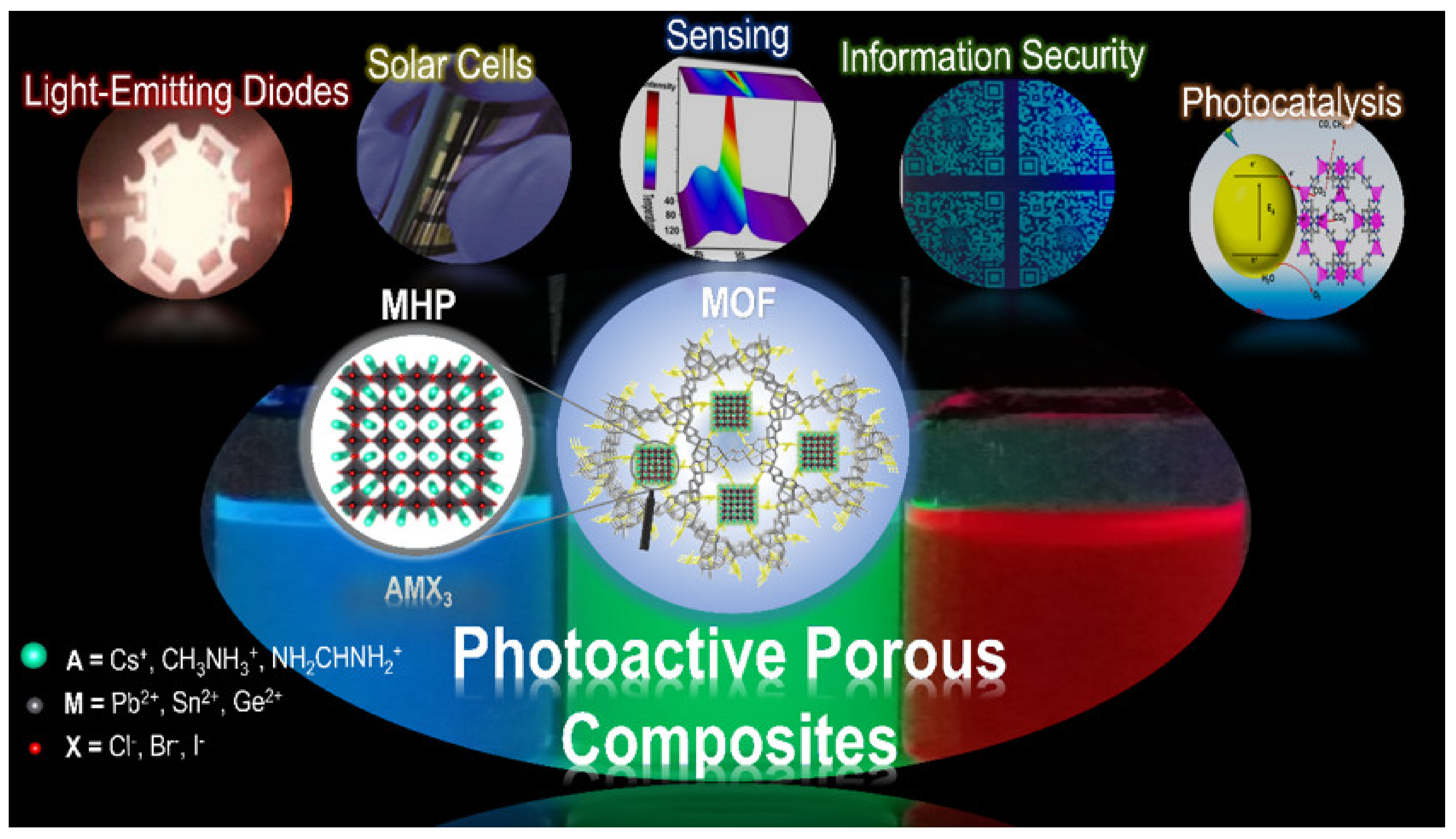
Figure 2.
Synthesis methodologies for preparing MHP@MOF composites: (a–d) ship-in-bottle methods including sequential deposition, in situ deposition, direct conversion, and physical mixture, and (e) bottle-around-ship method.
Figure 2.
Synthesis methodologies for preparing MHP@MOF composites: (a–d) ship-in-bottle methods including sequential deposition, in situ deposition, direct conversion, and physical mixture, and (e) bottle-around-ship method.
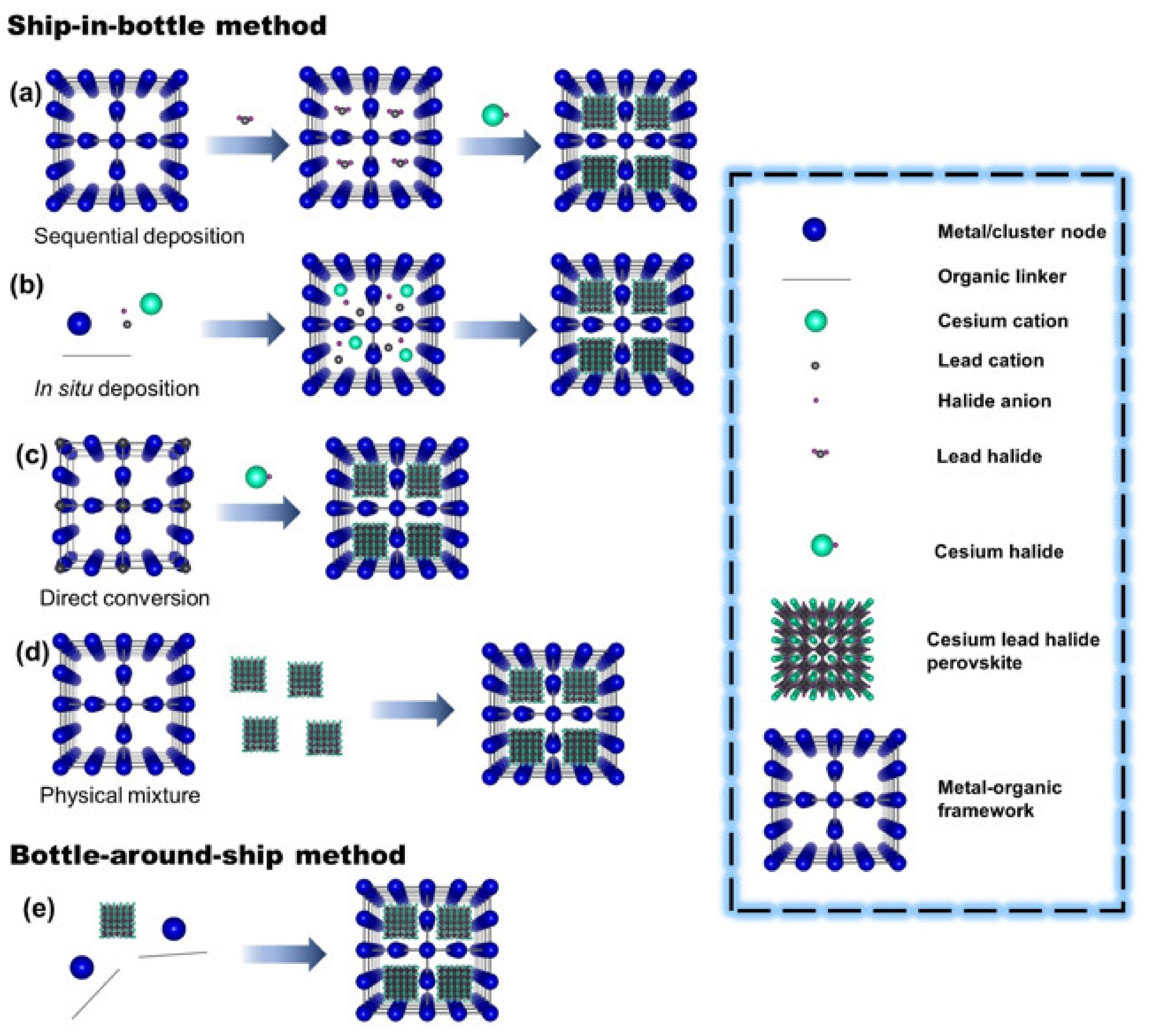
Figure 3.
(a) Proposed synthesis procedure for the formation of typical CsPbBr3@UiO-67 composite and the corresponding structural models. (b) PL spectrum of the as-fabricated WLEDs with CsPbBr3@UiO-67 composite and commercial K2SiF6:Mn4+ red phosphor deposited on the blue-chip (InGaN, 455 nm). Inset: Photograph of the WLEDs (x: 0.3690, y: 0.3437). (c) CIE colour space coordinates of as-fabricated WLEDs showing a wide colour gamut (138% NTSC). Adapted with permission from ref. [105]. Copyright 2019, American Chemical Society. (d) Synthesis strategy of the mesoporous MOF-5 crystals and the CsPbX3/MOF-5 composites. (e) PL spectrum of the CsPbX3/MOF-5, red CsPbBr0.6I2.4/MOF-5, and the blue InGaN chip (black line) compared with the NTSC standard (white line). (f) CIE colour coordinates of the W-LED device. Adapted with permission from ref. [126]. Copyright 2018, Elsevier B.V. All rights reserved. (g) Schematic of synthesis procedure of intense blue hybrid perovskite@MOG nanocomposite. (h) The emission spectrum of white LED fabricated by a combination of blue-emitting EAPbBr3@MOF (B), green-emitting MAPbBr3@MOG (G), and red-emitting Mn(II)-doped EAPbBr3 NCs (R) deposited on a UV chip. Inset: shows a photograph of the white LED with an applied current of 20 mA. (i) CIE colour coordinates of the as-fabricated white LEDs (x: 0.34, y: 0.32). Adapted with permission from ref. [128] under Creative Commons Attribution-NonCommercial 3.0 Unported License. (j) Mechanochemical synthesis of CsPbX3/ZIF-8 composites using CsBr/ZIF-8. (k) PL spectrum and corresponding white LED picture of white CsPbX3/ZIF-8 composite prepared by mixing blue, green, and red-light emitting components. (l) CIE colour coordinates of LEDs. Adapted with permission from ref. [109]. Copyright 2021, American Chemical Society.

Figure 4.
(a) The crystal structures of UiO-66 and (b) MOF-808 are illustrated. (c) The J-V curves of the MOF-modified devices measured under 1 sun. Adapted with permission from [114] under Creative Commons CC BY License. (d) Schematic of the synthesis protocol for nanocrystalline Ti-MOF (nTi-MOF). The successively linked TiO2 clusters with BDC molecules create small nanocrystals. The device structure of a flexible perovskite solar cell incorporating nTi-MOF/PCBM ETL. The magnified image indicates electron and hole transfer from the perovskite toward interlayers, nTi-MOF/PCBM and spiro-MeOTAD, respectively. (e) J-V curves of the flexible devices measured from r = ∞ to r = 3 mm and (f) bending test of the devices for r = 10 mm and r = 6 mm up to 700 bending cycles. Adapted with permission from [113]. Copyright 2018, American Chemical Society. (g) Crystal structure of MOF-525. Is illustrated (h) J-V curves of the perovskite and MOF/perovskite solar cells and (i) J-V curve of the best M5 cell. Inset: histogram of average PCE values of 40 devices. Adapted with permission from [111]. Copyright 2015, WILEY-VCH Verlag GmbH & Co. KGaA, Weinheim.
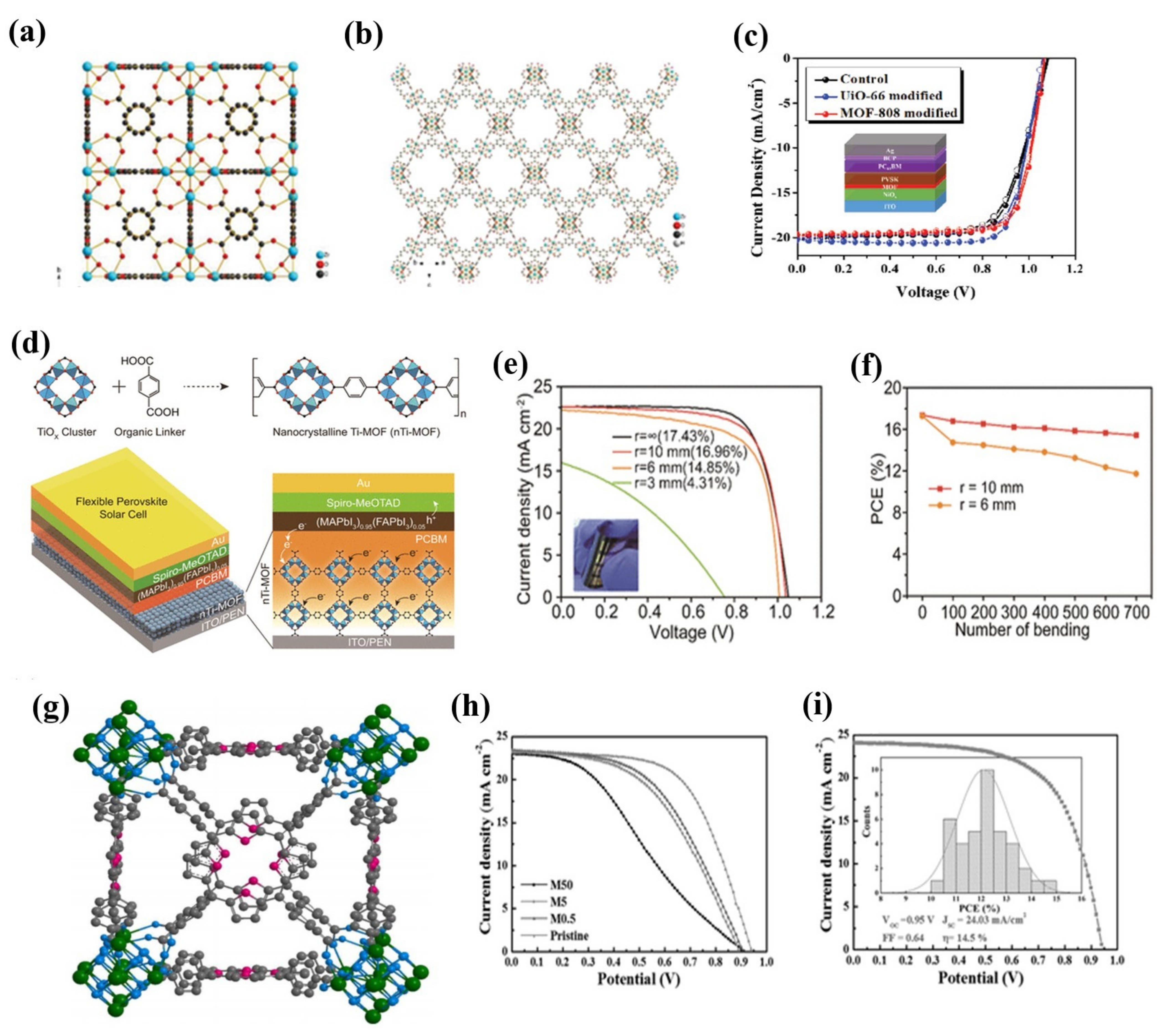
Figure 5.
(a) Schematic diagram of the two-step approach to CH3NH3PbBr3@MOF-5 composites. The first step included the synthesis of PbBr2@MOF-5 precursor by a solvothermal method, and the second step involved the addition of CH3NH3Br solvent for the final CH3NH3PbBr3@MOF-5. Illustrative images of the PbBr2@MOF-5 precursor, the CH3NH3PbBr3@MOF-5 composite (under daylight and 365 nm UV-light excitation) and its fluorescence microscope morphology. (b) PL spectra of CH3NH3PbBr3@MOF-5 composites depending on various Cu2+ ion concentrations. (c) Stern–Volmer plot for the F0/F values and different Cu2+ ion contents. (d) PL spectra of CH3NH3PbBr3@MOF-5 composites depending on various Cd2+ ion concentrations and (e) Stern–Volmer plot for the F0/F values and different Cd2+ ion contents. (f) PL spectra of CH3NH3PbBr3@MOF-5 composites depending on increasing temperature from 30 to 230 °C and (g) variation of the emission intensity depending on temperatures and a linear fitting. Adapted with permission from [120]. Copyright 2018, American Chemical Society. (h) Schematic illustration of the synthesis strategy of the mesoporous ZJU-28 and representative CsPbX3@ZJU-28. (i) The temperature-dependent PL spectra of CsPbBr3@ZJU-28 in 3D colour mapping surface with projection and (j) the relative emission intensity with temperature increases for the excitonic emission (518 nm) and the π-π* transitions (442 nm) of the CsPbBr3@ZJU-28 composite. (k) The plots of the luminescence intensity of I442/(I442 + I518) versus temperature and (l) temperature cycle test of the CsPbBr3@ZJU-28 composite between 20 and 160 °C. Adapted with permission under [126]. Copyright 2019, Elsevier B.V. All rights reserved. (m) Schematic illustration for the preparation process of CsPbBr3@Eu-BTC. (n) Temperature-dependent PL spectra of CsPbBr3@Eu-BTC in the temperature range of 20–100 °C excited at 339 nm (inset: the CIE (x,y) coordinate diagram of emission colours at various temperatures) and (o) integrated emission intensities of CsPbBr3@Eu-BTC QDs and Eu3+: 5D0–7F2 versus various temperatures. Adapted with permission from [121]. Copyright 2020, American Chemical Society.
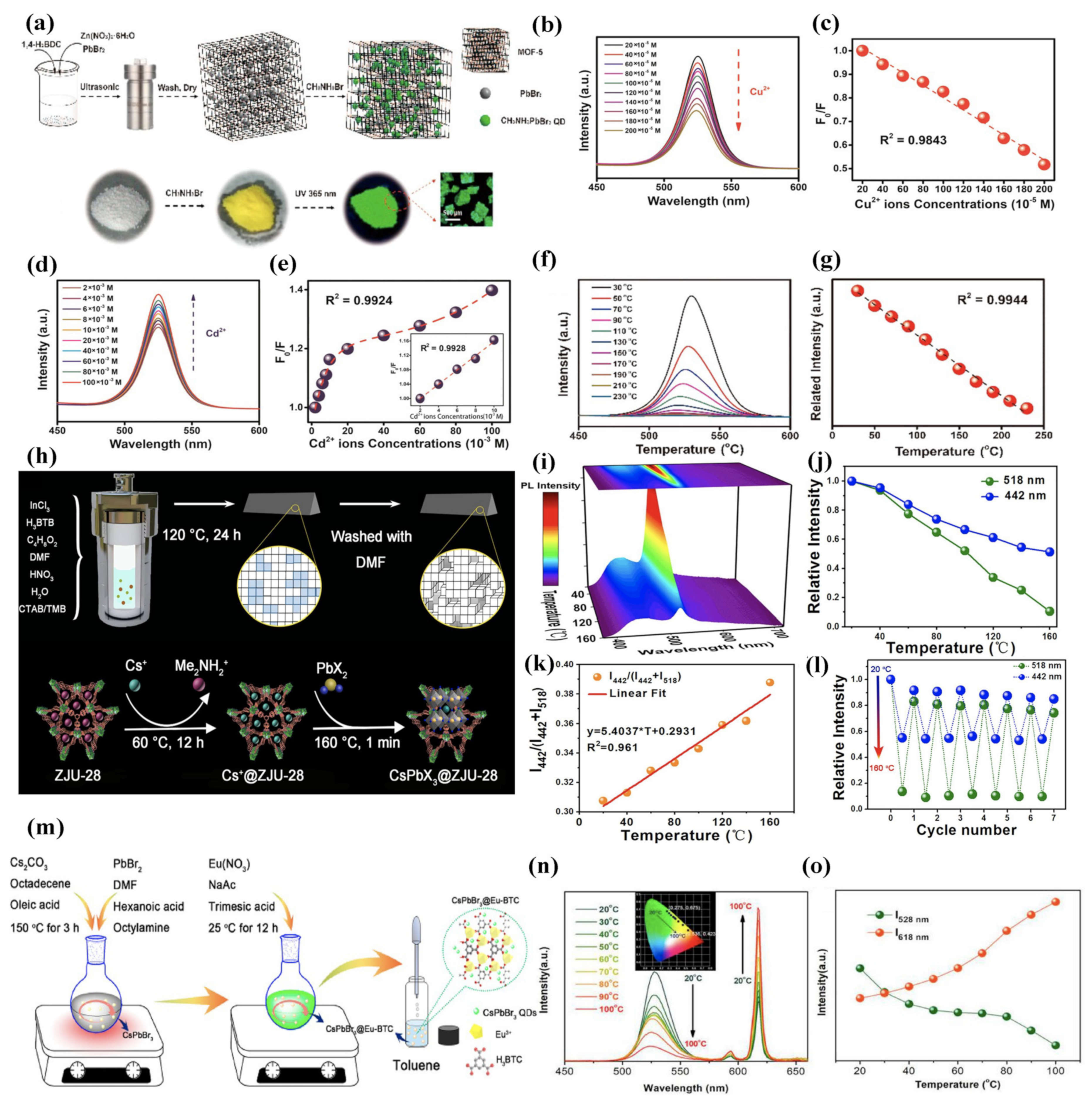
Figure 6.
(a) Schematic of the conversion process. MAX represents the halide salt (CH3NH3X, X = Cl, Br, or I). The green spheres in the matrix represent the MAPbBr3 NCs. The two black boxes show 3D crystal structure of the Pb-MOF (left) and MAPbBr3 (right). The Pb coordination polyhedra (the Pb atoms are coordinated by nine O atoms, in which two O atoms of one carboxylate coordinate to a Pb and also bridge two adjacent Pb atoms) and MAPbBr3 is represented in orange and green, respectively. Other atom colour schemes: C = grey, O = red, N = blue, Br = yellow. H-atoms have been omitted for clarity. Optical images of MAPbBr3 NCs@Pb-MOF powder under ambient light and 365 nm UV lamp. (b) Sequential optical images and PL emission spectra of MAPbBr3 NCs@Pb-MOF after one cycle of the impregnation-recovery process; 1, 2, and 3 represent the original, impregnated, and recovered powder sample of MAPbBr3 NCs@Pb-MOF, respectively. (c) PL intensity, peak wavelength, and FWHM of MAPbBr3 NCs@Pb-MOF in the impregnation-recovery cycles as a function of cycle number. (d) Reversible fluorescence switching of the MAPbBr3 NCs@Pb-MOF pattern in one encryption–decryption cycle (methanol impregnation for encryption and MABr spraying for decryption). Adapted with permission from [122] under a Creative Commons Attribution 4.0 International License. (e) Schematic illustration targeted the two-step fabrication of CH3NH3PbBr3@EuBTC composites, including (1) the PbBr2@EuBTC precursor prepared by a solvothermal method and (2) CH3NH3PbBr3@EuBTC composites precipitated with the addition of CH3NH3Br solution. The two dotted frames give the crystal structures of the PbBr2@EuBTC and CH3NH3PbBr3@EuBTC along the b and c axes. (f) Reversible fluorescence switching of the USTB pattern written on a paper at different stages and different excitation wavelengths of 254 nm and 365 nm. SEM images of USTB pattern on a paper at 200 μm and 5 μm. Adapted with permission from [123]. Copyright 2018, American Chemical Society.
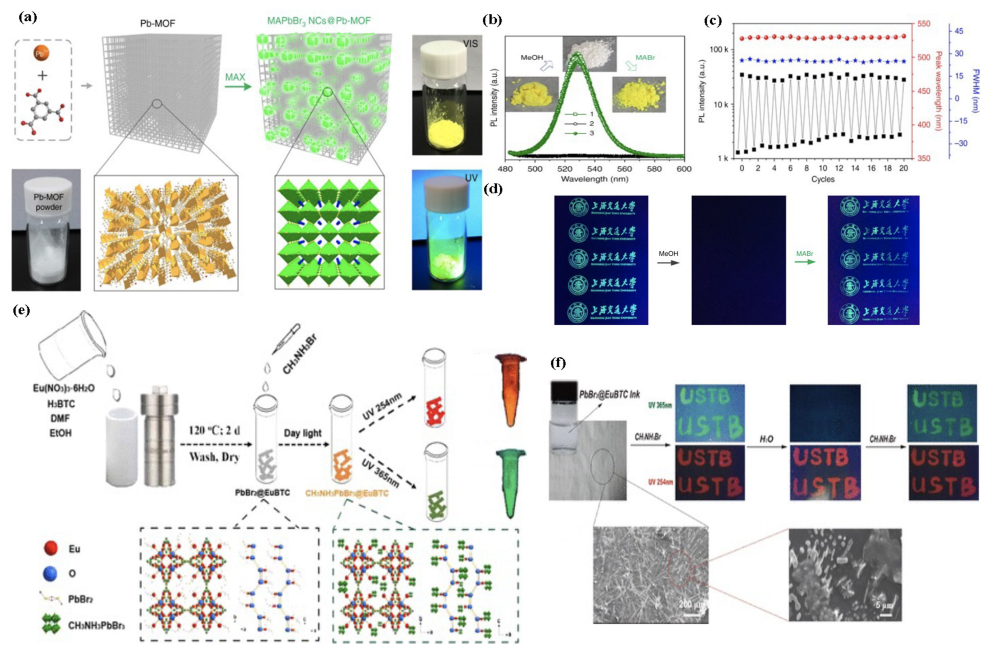
Figure 7.
(a) Schematic illustration of the fabrication process and CO2 photoreduction process of CsPbBr3/ZIFs. (b) UV-vis absorption spectra and (c) steady-state PL spectra. (d) Product yield after 3 h of photocatalytic reaction and (e) recycling test of CsPbBr3@ZIF-67 6 times with CO2 refilled every 3 h. Adapted with permission from ref. [127]. Copyright 2018, American Chemical Society. (f) Pore-Encapsulated Solvent-Directed (PSD) procedure for preparing HBP@MOF composites. (g) Absorption spectra changes of MO solution degraded by MAPbBr3 composite under visible light irradiation for different time intervals. The inset photograph shows degradation MO by composite for 0, 10, 25, 60, and 100 min (from left to right) and (h) degradation of MO by ZIF-8 under visible light. (i) Recyclability test for MAPbBr3 composite after photocatalytic degradation. The blue colour denotes the concentration of MO molecules before photocatalysis reaction, and the red colour denotes the concentration of MO molecules after photocatalysis reaction and effects of different quenchers for degradation of MO by the composite under visible light. (j) The degradation of MO is much prevented for IPA solution (green line), a widely used hydroxyl radical scavenger, confirming that hydroxyl radicals produced during the process are mainly responsible for photocatalytic dissociation of MO. (k) Schematic of the photocatalysis reaction mechanism. Adapted with permission from [128]. Copyright 2019, American Chemical Society.
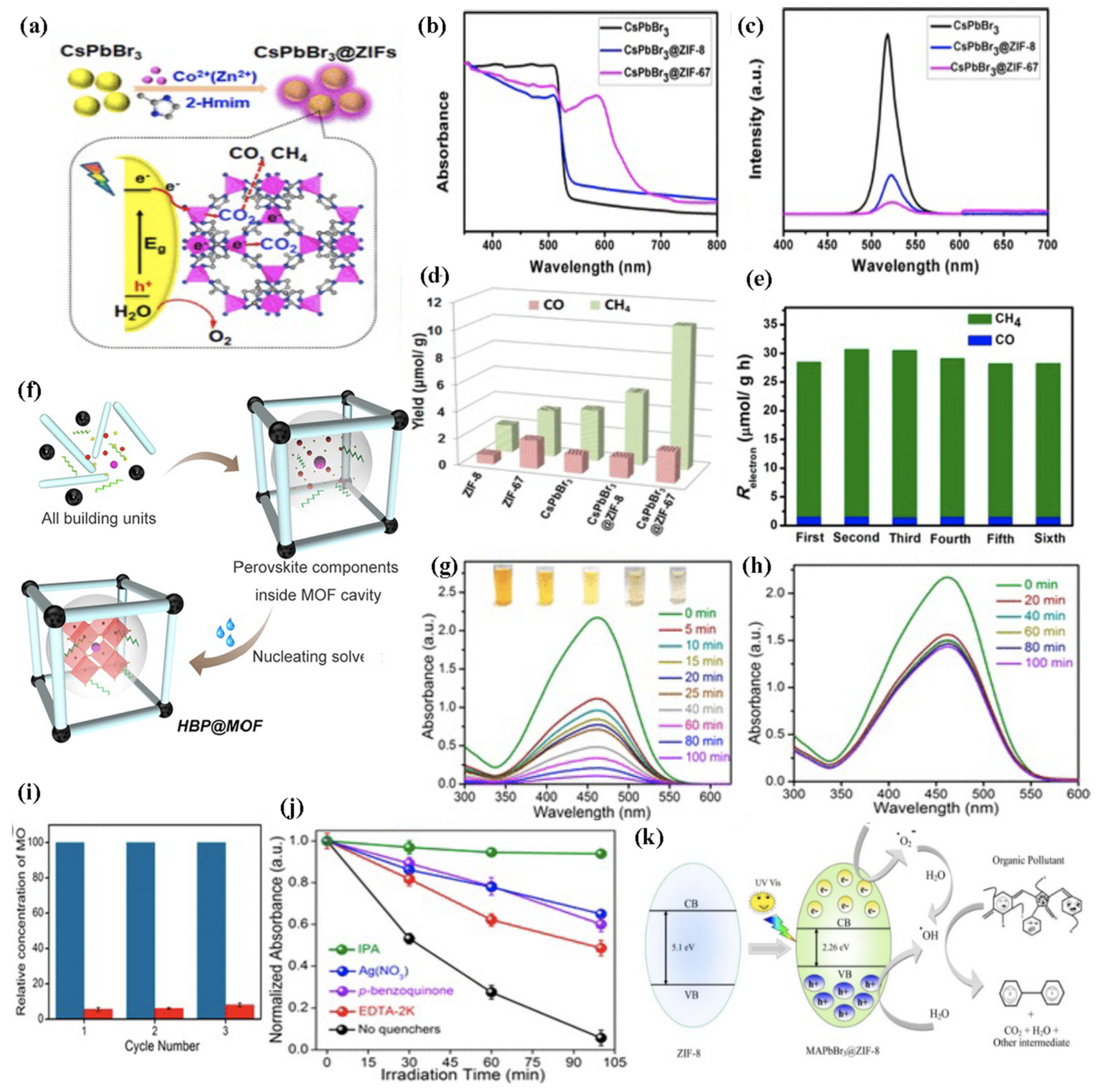

Table 1.
Summary table of the composition, synthesis methodology, structural and optical properties, and applications of the MHP@MOF composites.
Table 1.
Summary table of the composition, synthesis methodology, structural and optical properties, and applications of the MHP@MOF composites.
| MHP@MOF Composite | Synthesis Strategy | MOFs | Pore Size (nm) a | MHP | MHP Size (nm) | λem (nm) b | ΦPL (%) c | Application [Ref] |
|---|---|---|---|---|---|---|---|---|
| MAPbX3@HKUST-1 | Ship-in-Bottle (Sequential Deposition) | HKUST-1 [Cu3(BTC)2, BTC = 1,3,5-benzene tricarboxylate] | 1.66 | MAPbI2Cl MAPbI2Br MAPbI3 | 1.5–2 | 536 655 715 | - - - | Luminescence [101] |
| MAPbBr3@ZJU-28 | Ship-in-Bottle (Sequential Deposition) | ZJU-28 (ZJU-28 = [In3(BTB)4](Me2NH2)3) | - | MAPbBr3 | 7.7 11 | 509 530 | 51 | Multiphoton Exciton Luminescence [102] |
| CsPbX3@MIL-101 | Ship-in-Bottle (Sequential Deposition) | MIL-101(Cr) | 3 | CsPbCl3 CsPbCl2Br CsPbCl1Br2 CsPbBr3 CsPbBr2I CsPbBr1I2 CsPbI3 | 1.14 | 417 426 454 520 569 633 698 | - - - - - - - | Tunable Emission [103] |
| MAPbBr3@LnMOF | Ship-in-Bottle (Sequential Deposition) | LnMOF [Ln(tpob)(MDF)(H2O)]n, (Lntpob, Ln = Nd, Sm, Eu, Gd, Tb, Dy, H3tpob = 1,3,5-tris(4-carbonylphenyloxy)benzene) | - | MAPbBr3 | - | 515 | - | Tunable Emission [104] |
| CsPbX3@UiO-67 | Ship-in-Bottle (Sequential Deposition) | UiO-67 | 12 16 | CsPbBr3 CsPbBr1.2I1.8 | - - | 521 634 | 39 30 | Light-Emitting Diodes [105] |
| CsPbX3@MOF-5 | Ship-in-Bottle (Physical Mixing) | MOF-5 | 25 | CsPbBr3 CsPbBr0.6I2.4 | 9.49 | 519 655 | 52 56 | White Light-Emitting Diodes [106] |
| MAPbBr3@Bio-MOF-1 | Ship-in-Bottle (Sequential Deposition) | Bio-MOF-1 (Zn8(Ad)4(BPDC)6O·2Me2NH2, Ad = adeninate; BPDC = biphenyl-dicarboxylate) | - | MAPbBr3 | - | 519 (417,465) | 16 | Light-Emitting Diodes [107] |
| EAPbBr3@MIL-100(Al) | Ship-in-Bottle (in situ Deposition) | MIL-100(Al) (MOG) | 2.5–10 | EAPbBr3 | 3–11 | 436 | 53 | Light-Emitting Diodes [108] |
| CsPbX3@ZIF-8 | Ship-in-Bottle (Sequential Deposition) d | ZIF-8 | 5.7 | CsPbCl3 CsPbBr3 CsPbI3 | 5–10 | - 520 - | 51 72 57 | Light-Emitting Diodes [109] |
| MAPbI3/MIL-125 | - | MIL-125 | - | MAPbI3 | Bulk | - | - | Photovoltaic [110] |
| MAPbClxI3-x/MOF-525 | - | MOF-525 | 1.8 | MAPbClxI3-x | Bulk | - | - | Photovoltaic [111] |
| MAPbI3/ZIF-8 | - | ZIF-8 | - | MAPbI3 | Bulk | - | - | Photovoltaic [112] |
| MA0.95FA0.05PbI3/MIL-125(Ti) | - | MIL-125(Ti) | - | MA0.95FA0.05PbI3 | Bulk | - | - | Photovoltaic [113] |
| MAPbI3/UiO-66 MAPbI3/MOF-808 | Ship-in-Bottle (Sequential Deposition) | UiO-66 (Zr6O4(OH)4(BDC)6) MOF-808 (Zr6O4(OH)4(BTC)2(HCOO)6) | 1.3 1.9 | MAPbI3 | 720 e 640 e | - | - | Photovoltaic [114] |
| Cs0.1FA0.747MA0.153PbI2.49Br0.51/[Cu2(BTC)4/3(H2O)2]6 | - | [Cu2(BTC)4/3(H2O)2]6 | - | Cs0.1FA0.747MA0.153 PbI2.49Br0.51 | Bulk | - | - | Photovoltaic [115] |
| MAPbI3/Co-doped-Ti-MOF | - | Co-Doped-Ti-MOF | 6.79 | MAPbI3 | Bulk | - | - | Photovoltaic [116] |
| APbI3/ZIF-8 | - | ZIF-8 | - | (Cs/MA/FA)PbI3 | Bulk | - | - | Photovoltaic [117] |
| APbI3/Zn-cbpp | - | 2D Zn-cbpp [Zn(cbpp)(HCOO)]n, [hcbpp = 1-[4-carboxylbenzyl]-3-[pyrzin-2-yl]pyrazole] | - | (Cs/MA/FA)PbI3 | Bulk | 744 | - | Photovoltaic [118] |
| MAPbBr3/X-LH2 | Ship-in-Bottle (Sequential Deposition) | Zr-LH2 In-LH2 Zn-LH2 [(pydaH2)2+(pydc)2−, pyda = 2,6-pyridinediamine; pydcH2 = 2,6-pyridinedicarboxylic acid] | - | MAPbBr3 | 49 34 46 | - | - | Photovoltaic [119] |
| MAPbBr3@MOF-5 | Ship-in-Bottle (Sequential Deposition) | MOF-5 | 1.28 | MAPbBr3 | - | 533 (428) | 38 | Temperature Sensing, Metal Ion Detection [120] |
| CsPbBr3@Eu-BTC | Ship-in-Bottle (in situ Deposition) | Eu-BTC | - | CsPbBr3 | - | 528 (593,618) | - | Temperature Sensing [121] |
| MAPbX3@Pb-MOF | Ship-in-Bottle (Direct Conversion) | Pb-MOF (Pb2(1,3,5-HBTC)2-(H2O)4) | - | MAPbCl3 MAPbCl2Br1 MAPbClBr2 MAPbBr3 MAPbBr2I MAPbBrI2 MAPbI3 | - - - 10–20 - - - | 406 443 487 527 582 687 746 | - - - 40 - - - | Information Security [122] |
| MAPbBr3@Eu-BTC | Ship-in-Bottle (Sequential Deposition) | Eu-BTC | - | MAPbBr3 | - | 513 (593,617) | 42 | Information Security [123] |
| MAPbBr3@UiO-66 | Ship-in-Bottle (Sequential Deposition) | UiO-66 | 0.69 | MAPbBr3 | - | 505 | - | Information Security [124] |
| CsPbX3@AMOF-1 | Ship-in-Bottle (Sequential Deposition) d | AMOF-1 (L = 5,5′-(1,4-phenylenebis(methylene))bis(oxy)diisophthalate) | - | CsPbCl3 CsPbBr3 CsPbI3 | 2–9 2–9 5–8 | 412 515 695 | 2 14 5 | Information Security [125] |
| CsPbX3@ZJU-28 | Ship-in-Bottle (Sequential Deposition) | ZJU-28 | - - 23.56 - - - | CsPbCl3 CsPbCl1.5Br1.5 CsPbBr3 CsPbBr1.5I1.5 CsPbBr0.6I2.4 CsPbI3 | 7.92 9.21 11.85 12.87 13.74 15.65 | - - 518 (445,478) - - | - - 62 - - - | Information Security, Temperature Sensing, Light-Emitting Diodes [126] |
| CsPbBr3@ZIF-8 CsPbBr3@ZIF-67 | Bottle-Around-Ship | ZIF-8 ZIF-67 | - - | CsPbBr3 | 5 | 524 | - | Photocatalysis [127] |
| APbBr3@ZIF-8 | Ship-in-Bottle (in situ Deposition) | ZIF-8 | 1.16 | MAPbBr3 MA0.75EA0.25PbBr3 MA0.5EA0.5PbBr3 MA0.25EA0.75PbBr3 EAPbBr3 | 6–8 - - - - | 527 493 481 455 < 440 | 80 - - - - | Photocatalysis [128] |
| CsPbBr3@UiO-66(NH2) | Ship-in-Bottle (Physical Mixing) | UiO-66(NH2) | - | CsPbBr3 | 10 | - | - | Photocatalysis [129] |
| MAPbI3@PCN-221(Fex) | Ship-in-Bottle (Sequential Deposition) | PCN-221(Fex) (x = 0–1) | 2 | MAPbI3 | 1.8 | 610 | - | Photocatalysis [130] |
| MAPbBr3@ MA-M(HCOO)3 | Ship-in-Bottle (Sequential Deposition) d | MA-M(HCOO)3 [M = Mn, Co] | - | MAPbBr3 | 5–10 | 520 | <3 | Photo-Electrochemical Activity [131] |
| APbBr3@Cr-MIL-101 | Ship-in-Bottle (Sequential Deposition) | Cr-MIL-101 [(Cr3O(OH)(H2O)2(terephthalate)3] | 2.9 3.4 | CsPbBr3 MAPbBr3 FAPbBr3 | 3 | 440 446 450 | <5 | - [132] |
[a] Pore size of the MOF before encapsulation. [b] Emission wavelength of MHP in the composite. The wavelength in brackets refers to that of the MOF host. [c] Photoluminescence quantum yield of MHP in the photoactive porous composite. [d] Synthesis of photoactive porous composite carried out in the absence of solvent. [e] Grain size of perovskite film.
Publisher’s Note: MDPI stays neutral with regard to jurisdictional claims in published maps and institutional affiliations. |
© 2021 by the authors. Licensee MDPI, Basel, Switzerland. This article is an open access article distributed under the terms and conditions of the Creative Commons Attribution (CC BY) license (https://creativecommons.org/licenses/by/4.0/).
Share and Cite
MDPI and ACS Style
Cortés-Villena, A.; Galian, R.E. Present and Perspectives of Photoactive Porous Composites Based on Semiconductor Nanocrystals and Metal-Organic Frameworks. Molecules 2021, 26, 5620. https://doi.org/10.3390/molecules26185620
AMA Style
Cortés-Villena A, Galian RE. Present and Perspectives of Photoactive Porous Composites Based on Semiconductor Nanocrystals and Metal-Organic Frameworks. Molecules. 2021; 26(18):5620. https://doi.org/10.3390/molecules26185620
Chicago/Turabian StyleCortés-Villena, Alejandro, and Raquel E. Galian. 2021. "Present and Perspectives of Photoactive Porous Composites Based on Semiconductor Nanocrystals and Metal-Organic Frameworks" Molecules 26, no. 18: 5620. https://doi.org/10.3390/molecules26185620