Article

Numerical Study On Local Entropy Generation In Compressible Flow Through A Suddenly Expanding Pipe

Erciyes Üniversitesi Mühendislik Fakültesi, 38039 Kayseri,Turkey
*
Author to whom correspondence should be addressed.
Entropy 2005, 7(1), 38-67; https://doi.org/10.3390/e7010038
Submission received: 8 December 2004 / Accepted: 8 February 2005 / Published: 11 February 2005

Abstract

:
This study presents the investigation of the local entropy generation in compressible flow through a suddenly expanding pipe. Air is used as fluid. The air enters into the pipe with a turbulent profile using 1/7 th power law. The simulations are extended to include different expansion ratios reduced gradually from 5 to 1. To determine the effects of the mass flux, ϕ′′, the ambient heat transfer coefficient, hamb, and the inlet temperature, Tin, on the entropy generation rate, the compressible flow is examined for various cases of these parameters. The flow and temperature fields are computed numerically with the help of the Fluent computational fluid dynamics (CFD) code. In addition to this CFD code, a computer program has been developed to calculate numerically the entropy generation and other thermodynamic parameters by using the results of the calculations performed for the flow and temperature fields. The values of thermodynamic parameters in the sudden expansion (SE) case are normalized by dividing by their base quantities obtained from the calculations in the uniform cross-section (UC) case. The contraction of the radius of the throat (from 0.05 to 0.01 m) increases significantly the maximum value of the volumetric entropy generation rate, (about 60%) and raises exponentially 11 times the total entropy generation rate with respect to the its base value. The normalized merit number decreases 73% and 40% with the contraction of the cross-section and with the increase of the ambient heat transfer coefficient (from 20 to 100 W/m2-K), respectively, whereas it rises 226% and 43% with the decrease of the maximum mass flux (from 5 to 1 kg/m2-s) and with the increase of the inlet temperature (from 400 to 1000 K), respectively. Consequently, the useful energy transfer rate to irreversibility rate improves as the mass flux decreases and as the inlet temperature increases.

Nomenclatureq"heat flux per unit area
Aarea Q ˙ heat transfer rate
BeBejan number Q ˙ a exergy transfer rate
Cµcoefficient in k-ε turbulence modelrradial distance
C1εcoefficient in k-ε turbulence modelRradius of pipe
C2εcoefficient in k-ε turbulence model ideal gas constant
CFDcomputational fluid dynamicsRNGrenormalization group
CPspecific heat at constant pressureSmodulus of the mean rate-of-strain tensor
ERexpansion ratioSijmean strain rate
Gkthe production of turbulent kinetic energySEsudden expansion
hheat transfer coefficient S gen volumetric entropy generation rate
I ˙ irreversibility rate S ˙ gen integrated entropy generation rate
kturbulent kinetic energyttime
Llength of pipeTtemperature
Mmerit numberψarbitrary field variable
Ppressure
uvelocity component in the axial directionSuperscript
UCuniform cross-section*normalized
UDFuser defined function
vvelocity component in the radial directionSubscripts
Vvolume0base
xaxial distanceambambient
awaarea-weighted average
Greek symbols effeffective
αinverse effective Prandtl numberfricfriction
βmodel constantheatheat transfer
χadditional term in the ε equationipart no
εturbulent energy dissipation ratei,jindices of tensor notation
φarbitrary variableininlet
η0model constantjcell number
ϕ′′mass flux per unit areamaxmaximum
Φviscous dissipationopoperation condition
λthermal conductivitytturbulent
µdynamic viscosityTthroat
ρdensitywwall

Introduction

The viscous flow through pipes with axisymmetric sudden expansions in cross-sectional area has both fundamental scientific interest and numerous practical applications: such flows occur, for example, in pipe-flow systems in the chemical, pharmaceutical and petroleum industries, in air-conditioning ducts, around buildings, in dump combusters and in fluidic devices. Sudden expansion flows bring together geometric simplicity with a not to simple flow behavior. A number of analytical and experimental investigations on this type of flow have been reported in recent years, and some comprehensive studies have been carried out to explore the flow characteristics in the laminar and mainly in the turbulent flow regimes [1,2,3,4,5,6,7,8].
Entropy analysis of the flow system provides useful information about the flow field. In this case, the local losses due to fluid friction and heat transfer can be identified easily. The entropy generation rates within a flow domain can be expressed as the sum of contributions due to viscous effects and thermal effects, and thus it depends functionally on the local values of velocity and temperature in the domain of interest. Energy conversion processes are accompanied by an irreversible increase in entropy, which leads to a decrease in exergy (available energy). Thus, even though the energy is conserved, the quality of the energy decreases because energy is converted into a different form of energy, from which less work can be obtained. Reduced entropy generation will result in more efficient designs of energy systems. Therefore, in recent years, entropy minimization has become a topic of great interest in the thermo-fluid area. The second-law analysis of heat transfer in swirling flow through a cylindrical duct was investigated by Mukherjee et al. [9]. They calculated the rate of entropy generation. They defined also a merit function and discussed influence of swirling on this merit function. Bejan [10] focused on the different reasons behind entropy generation in applied thermal engineering where the generation of entropy destroys the available work (exergy) of a system. Therefore, it makes good engineering sense to focus on the irreversibility of heat transfer and fluid flow processes, and to try to understand the function of associated entropy generation mechanisms. Bejan [11] also conducted an extensive review on entropy generation minimization. The review traced the development and adoption of the method in several sectors of mainstream thermal engineering and science. Furthermore, many researchers carried out studies on the entropy generation in various flow cases. Sahin et al. [12,13,14,15,16,17], Shuja et al. [18, 19], Yilbas et al. [20,21], Demirel et al. [22], Hyder et al. [23], Abbassi et al. [24] performed many studies on second law analysis and the entropy generation due to the heat transfer and fluid friction in duct flows under various conditions. Mahmud and Fraser [25] also investigated the thermodynamic analysis of flow and heat transfer inside a channel with two parallel plates and [26] the second law analysis in fundamental convective heat transfer problems. Shuja et al. [27] analyzed the entropy generation in an impinging jet and [28,29,30] swirling jet impingement on an adiabatic wall for various flow conditions. The influence of fluid viscosity on the entropy generation due to turbulent pipe flow heated from the pipe wall at constant temperature is investigated by Al-Zaharnah and Yilbas [31]. Furthermore, Hijleh et al. [32] calculated for three radii and a wide range of Rayleigh numbers for an isothermal cylinder, Haddad et al. [33] studied on the entropy production due to laminar forced convection in the entrance region of a concentric cylindrical annulus, and Yapici et al. [34] investigated the local entropy generation in a methane-air burner and [35] in the pulsating turbulent and [36] laminar flow through an externally heated pipe.
The general theory of fluid motion is too difficult to enable the user to attack arbitrary geometric configurations. It is possible to apply merely numerical techniques to arbitrary geometries. CFD stands for computational fluid dynamics. It refers to a technique or actually techniques for approximately solving the equations of fluid dynamics. It turns out the methods are applicable to a number of systems of equations which fall under the category of conservation laws. Therefore, a suitable numerical method and/or computational fluid dynamics code is frequently used to solve the governing equations in this field. The CFD code is the program by which fluid flow can be predicted through arbitrary geometries, giving such information as flow speed, pressures, residence times, flow patterns, etc. The main advantage of this approach is in its potential for reducing the extent and number of experiments required to describe such types of flow.
In our previous studies [35, 36] , the transient local entropy generation rate due to the temperature and velocity gradients in pulsating fully developed turbulent and laminar flow through an externally heated pipe have been carried out. The present study considers the numerical solution of the local entropy generation in a suddenly expanding pipe with fully developed turbulent flow inlet conditions. In order to investigate the effects of the flow and boundary condition parameters (mass flux, throat radius, inlet temperature, and ambient heat transfer coefficient) on the entropy generation rate, the flow is examined for various values of these parameters by using Fluent CFD code [37].

Mathematical Model
Pipe geometry

In this study, the numerical solution of the local entropy generation in compressible flow through a suddenly expanding pipe is analyzed. The two-dimensional axisymmetric model of the considered pipe is shown in Figure 1. Air is used as fluid. In order to provide the highspeed flow and simulate the sudden expansion (SE), the pipe is designed as two parts connected with each other: (1) the converging part with the varying cross-section and (2) the uniform part. The radius and lengths of the pipe parts are R and Li, respectively, (i denotes the part no). The radius of throat, RT, is expanded gradually from 0.2R to 1.0R. In other words, the expansion ratio, ER, which is the ratio of the pipe radius to the throat radius (R/RT), is reduced gradually from 5 to 1. ER = 1 means that the pipe cross-section is uniform along the whole pipe (the uniform cross-section, UC, case). The air enters into the pipe with a turbulent profile using 1/7 th power law. It is assumed that the wall of the converging part and the left wall of the uniform part are insulated and that the other wall of the uniform part is under the ambient conditions. The numerical calculation is performed individually for the each ER. The effects of the mass flux, ϕ′′, the ambient heat transfer coefficient, hamb, and the inlet temperature, Tin, on the entropy generation rate are also investigated.
As is apparent from the above explanations, in this analysis, two phenomena are considered as follows: i) the heat transfer inside the pipe, ii) the local entropy generation in the fluid flow. The analysis is based on two-dimensional continuity, momentum, and energy equations.

Mathematical model

The assumptions made are as follows:
-
The air is assumed to behave as an ideal gas.
-
The thermo-physical properties of air vary with temperature.
-
The flow is steady, two-dimensional axisymmetric, turbulent and compressible.
-
The thickness of the pipe is neglected.
-
The gravity effect is negligible.
-
No-slip condition is assumed at the pipe wall.

The governing conservation equations

The governing equations for the steady-state turbulent compressible flow and heat transfer in the flow region (-L1≤ x ≤ L2 and 0 ≤ r ≤ R) can be written as follows:
Continuity:
x ( ρ u ) + 1 r r ( ρ r v ) = 0
Axial momentum:
1 r x ( r ρ u u ) + 1 r r ( r ρ u v ) = P x + 1 r x { r μ [ 2 u x 2 3 ( u x + v r + v r ) ] } + 1 r r [ r μ ( u r + v x ) ]
Radial momentum:
1 r x ( r ρ u v ) + 1 r r ( r ρ v v ) = P r + 1 r x [ r μ ( v x + u r ) ] + 1 r r { r μ [ 2 v r 2 3 ( u x + v r + v r ) ] } 2 μ v r 2 + 2 3 μ r ( u x + v r + v r )
Energy:
x ( u ( ρ C P T + P ) ) + 1 r r ( v ( ρ C P T + P ) ) = x ( λ e f f T x ) + 1 r r ( λ e f f r T r ) + μ Φ
where λeff is the effective conductivity and for the RNG k-ε model,
λeff = α⋅CP ⋅ µeff
where α, the inverse effective Prandtl number, is computed using the following formula derived analytically by the RNG theory:
| α 1.3929 α 0 1.3929 | 0.6321 | α + 2.3929 α 0 + 2.3929 | 0.3679 = μ μ eff
where
α 0 = λ μ C P
and µ is viscosity, Cp is specific heat, and Φ is viscous dissipation term, which is
Φ = 2 [ ( u x ) 2 + ( v r ) 2 + ( v r ) 2 ] + ( v x + u r ) 2
Two additional equations for the RNG k-ε turbulence model: The turbulence kinetic energy, k, and the dissipation rate, ε, are determined using the following transport equations, respectively:
x i ( ρ u i k ) = x i ( α k μ eff k x i ) + G k ρ ε
x i ( ρ u i ε ) = x i ( α ε μ eff ε x i ) + ε k ( C 1 ε G k C 2 ε ρ ε ) χ
where αk and αε are the inverse effective Prandtl numbers for k and ε, respectively, and are calculated from Eq. (3c) by using α0=1,
μ e f f = μ + μ t , μ t = ρ C μ k 2 ε ,
Cµ, C and C are the model constants,
G k = μ t S 2
and
χ = C μ ρ η 3 ( 1 η η 0 ) 1 + β η 3 ε 2 k
where S is the modulus of the mean rate-of-strain tensor, defined as
S = 2 S i j S i j
Sij (the mean strain rate) is given by:
S i j = 1 2 ( u i x j + u j x i )
η = S k ε ,
η0 = 4.38 , and β = 0.012.
Boundary conditions:
At the pipe inlet,
u ( L 1 , r ) = φ ( r ) ρ , v ( - L 1 , r ) = 0  and  T ( - L 1 , r ) = T i n
φ ( r ) = φ max ( 1 r R ) 1 / 7
where ϕ′′(r) is the mass flux per unit area and ϕmax is its maximum value.
At the isolated (adiabatic) walls,
T x = 0  and  T r = 0
At the pipe wall,
v(x,R) = 0,
the convective heat transfer is assumed, i.e.:
q"w (x) = −hamb[T(x,R) − Tamb],
and the no-slip conditions are assumed, i.e.:
u(x,R) = 0
Since, the profiles of velocity and temperature are both symmetric with respect to the axis of the pipe, the relevant boundary conditions at the pipe axis (r = 0) are
ϕ ( x , 0 ) r = 0
where φ is any arbitrary variable.
At the inlet and outlet planes,
T ( L 1 , r ) x = 0  and  T ( L 2 , r ) x = 0

Entropy generation rate

In the fluid flow, irreversibility arises due to the heat transfer and the viscous effects of the fluid. The entropy generation rate can be expressed as the sum of contributions due to viscous effects and thermal effects, and thus it depends functionally on the local values of velocity and temperature in the domain of interest. In these systems, when both temperature and velocity fields are known, the volumetric entropy generation rate ( S gen ) at each point can be calculated as follows [10]:
S gen = ( S gen ) heat + ( S gen ) fric
where ( S gen ) heat and ( S gen ) fric represent the entropy generation rates due to heat transfer and fluid friction, respectively, and they are defined as:
( S gen ) heat = λ eff T 2 [ ( T x ) 2 + ( T r ) 2 ]
( S gen ) fric = μ eff T Φ
The total entropy generation rate over the volume ( S ˙ gen ) can be calculated as follows:
S ˙ gen = V S gen θ r x
where V is the volume.
The Bejan number, Be, which compares the magnitude of entropy generation due to heat transfer to the magnitude of the total entropy generation, is defined by:
B e = ( S ˙ gen ) heat S ˙ gen
When Be >> 0.5, the irreversibility due to heat transfer dominates, while for Be << 0.5 the irreversibility due to viscous effects dominates. For Be ≅ 0.5 , entropy generation due to heat transfer is almost of the same magnitude as that due to fluid friction.
The merit number (M) is defined as the ratio of exergy transferred to the sum of exergy transferred and exergy destroyed [9], i.e.:
M = Q ˙ a Q ˙ a + I ˙
where I ˙ is the rate of total irreversibility and it is defined as:
I ˙ = T amb S ˙ gen
The rate of exergy transfer ( Q ˙ a ) accompanying energy transfer at the rate of Q ˙ is given as [9]:
Q ˙ a = Q ˙ [ 1 T amb ( T w ) awa ] ,
where Q ˙ is the heat transfer rate from the pipe wall to environment, which can be written as:
Q ˙ = A w | ( q w ) awa |
At the same time, this heat transfer rate corresponds to the energy change between the inlet and outlet.
The “awa” represents area-weighted average of relevant quantity, respectively. The areaweighted average of a quantity is computed by dividing the summation of the product of the selected field variable (ψj) and facet area (Aj) by the total area of relevant surface, (A):
( ψ ) awa = 1 A j = 1 n ψ j | A j |
To obtain the total entropy generation rate, firstly, it is necessary to solve the governing conservation equations, given in section 2.2.1. The volumetric local entropy generation rate can be calculated by using the local velocities and temperatures obtained from the calculations of the governing conservation equations, and the total entropy generation rate over the volume can be obtained using numerical integration. In order to evaluate more easily the relative variations of the thermodynamic parameters, defined with Eqs. (6d-i), in the SE case, with respect to those in the UC case, they are normalized by dividing by their base quantities obtained from the calculations in the UC case, i.e.:
ϕ * = ϕ ϕ 0
where the superscript, *, and the subscript, 0, represent the normalized value and the base value, respectively.

Computational Procedure
Calculational Tools

The FLUENT 6.1 program was chosen as the CFD computer code for this work because of the ease with which the analysis model can be created, and because the software allows users to modify the code for special analysis conditions through the use of user subroutines. The FLUENT computer code uses a finite-volume procedure to solve the Navier-Stokes equations of fluid flow in primitive variables such as u-velocity, v-velocity, and pressure. A variety of turbulence models is offered by the FLUENT computer code. A detailed description of turbulence models and its application to turbulence can be found in Ref. [37]. In the case of the k-ε models, two additional transport equations, Eqs. (4a,b) with sub-Eqs. (4c-i), (for the turbulent kinetic energy and the turbulence dissipation rate) are solved, and turbulent viscosity, µt, is computed as a function of k and ε. The RNG k-ε model belongs to the k-ε family of turbulence models; however, unlike the standard k-ε model, the RNG k-ε model was derived using a statistical technique called renormalization group methods. The model equations are similar to the standard k-ε. model, but the statistical derivation results in different values for the various constants in the equations. A more comprehensive description of RNG theory and its application to turbulence can be found in Refs. [38, 39]. The RNG-k-ε model was used as a turbulence model in this study. The model constants for the RNG-k-ε model are Cµ=0.0845, C=1.42, C=1.68 and wall Prandtl number=0.85. The solution method for this study is axisymmetric.
In order to define the mass fluxes varying with the radial position in all cases, an UDF (User Defined Function) file was introduced to the prepared FLUENT case file. The UDF files provide the capability to customize boundary conditions, source terms, property definitions (except specific heat), surface and volume reaction rates, user defined scalar transport equations, discrete phase model (e.g. body force, drag, source terms), algebraic slip mixture model (slip velocity and particle size), solution initialization, wall heat fluxes and post processing using user defined scalars, and so they can significantly enhance the capability of FLUENT. Furthermore, a computer program has been developed to calculate numerically the volumetric entropy generation rate distributions in Eqs. (6a-d) and the other thermodynamic parameters in Eqs. (6e-i), by using the results of the calculations performed with the FLUENT code. This program, written in FORTRAN 77 language, calculates numerically the axial and radial derivations of the temperature (T) and the components (ux and ur) of velocity, which are functions of the axial and radial distances. It uses the finitedifferences approach, and thus it calculates the volumetric entropy generation rate distributions and the other thermodynamic parameters as two dimensional.

Simulation Values

R = 0.05 m, L1 = 2R, L2 = 10R and RT = 0.2R, 0.3R,.., 1.0R (or ER = 10/2, 10/3,..,1). φmax = 5.0 kg/m2-s, Tin = 400 K, Tamb = 300 K and hamb = 20 W/m2-K.
For RT = 0.2R (ER=5), φmax = 1.0, 1.5,.., 5.0 kg/m2-s, Tin = 400, 500,.., 1000 K, and hamb = 20, 30,.., 100 W/m2-K.
The density of air, according to the ideal gas law for compressible flows, has the following form:
ρ = P o p + P T
where Pop is the operating pressure (Pop= 101325 Pa) and ℜ is the ideal gas constant (287 J/kg-K for air).
The other temperature-dependent thermo-physical properties of air at T = 270 to 1500 K and atmospheric pressure (101325 Pa) were obtained by curve-fitting to data, taken from Refs. [40,41,42] as follows:
CP = 1049.15 − 0.35361T + 8.16841⋅10−4T2 − 3.71508⋅10−7T3
λ = 3.93145⋅10−3 + 7.89143⋅10−5 T − 1.54631⋅10−8T2
µ = 3.59059⋅10−6 + 5.3986⋅10−8 T − 1.43383⋅10−11T2
Grid size: The grid independent tests were carried out to ensure grid independence of the calculated results; consequently, the grid size and the grid orientation giving the grid independent results were selected, and thus the total cell number of 100000 cells (1000x100) in the second part was adopted.

Numerical Results
Temperature and Velocity Distributions in the Uniform Section

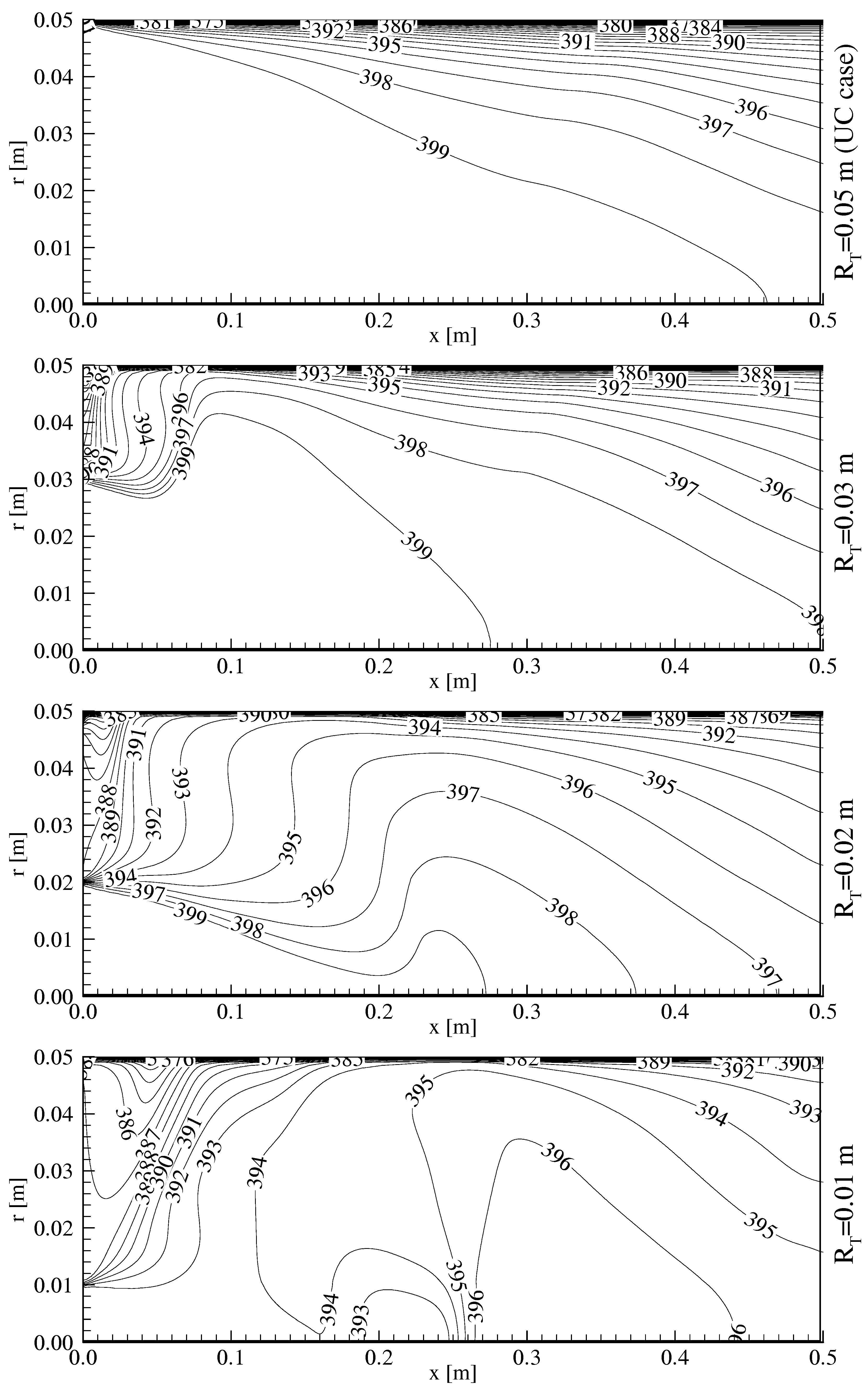
The uniform section of the pipe is under the ambient conditions while the converging section is insulated, and the inlet temperature of the fluid is relatively hotter than the ambient temperature. Therefore, the temperature of the fluid entering into the uniform section will decrease gradually towards the pipe wall and outlet, and the temperature gradients in the radial and axial directions will occur, which in turn will increase the local entropy generation. The two-dimensional temperature distributions within the uniform section of the pipe in the case of Tin=400 K, φmax=5 kg/m2-s and hamb=20 W/m2-K are countered in Figure 2 for the different throat radiuses (RT=0.05, 0.03, 0.02 and 0.01 m). One can see from this figure that the constant temperature contours extend further inside the fluid, and the relatively low temperature contours to the inlet temperature are developed in the region close to the pipe wall as the pipe length extends. This is because of the convective heating of the fluid in the vicinity of the pipe wall. Furthermore, as the throat radius contracts (RT= 0.05 to 0.01 m, the heat transfer from the pipe wall to the environment increases from 216 to 238 W due to the increasing of the turbulence intensity, and as a result of this, the pipe wall temperature increases from 369 to 375 K. However, in the case of the large throat cross-sections, the centerline temperature does not change significantly (about 399 K) because the sufficient cool penetration does not reach this region.
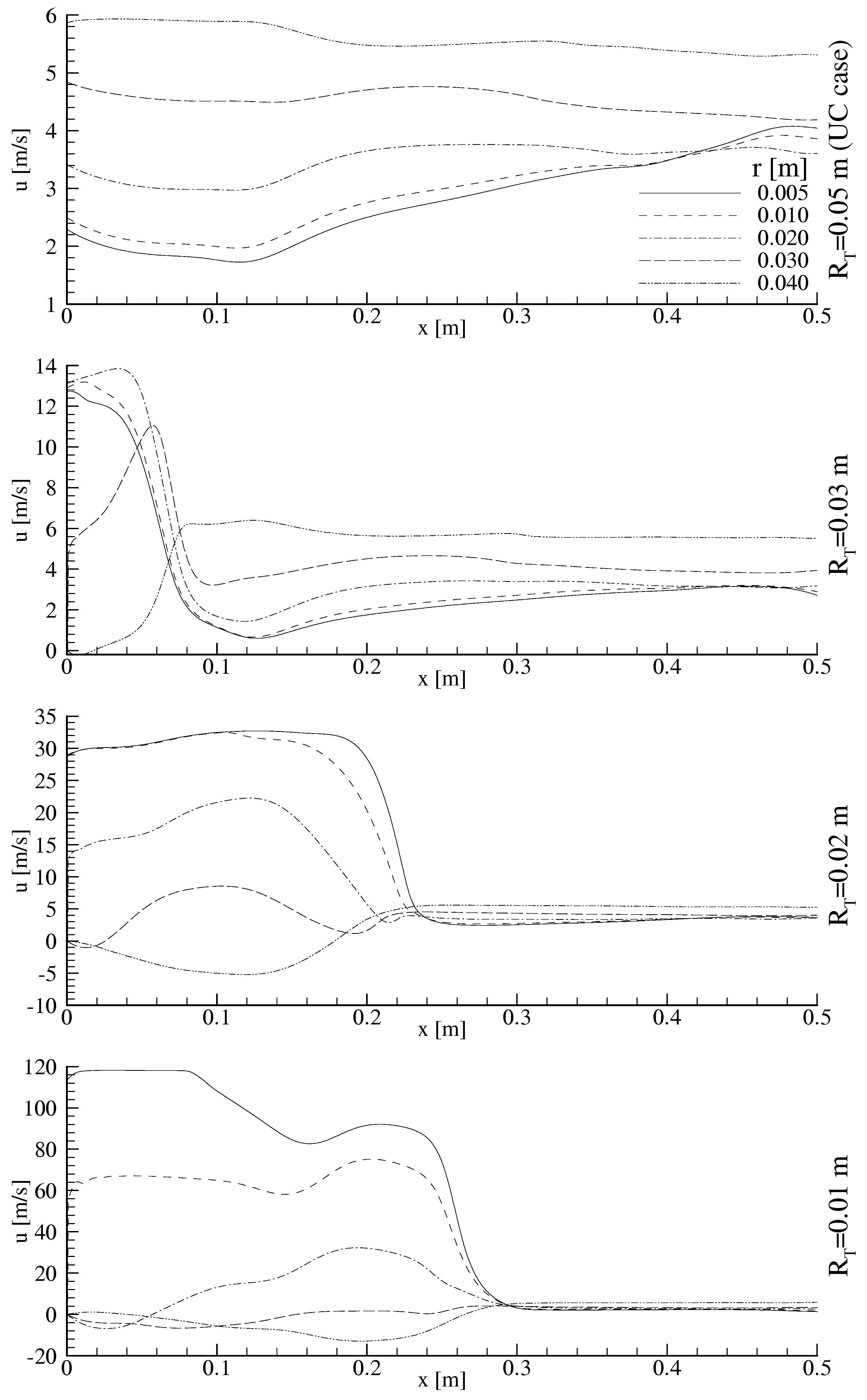
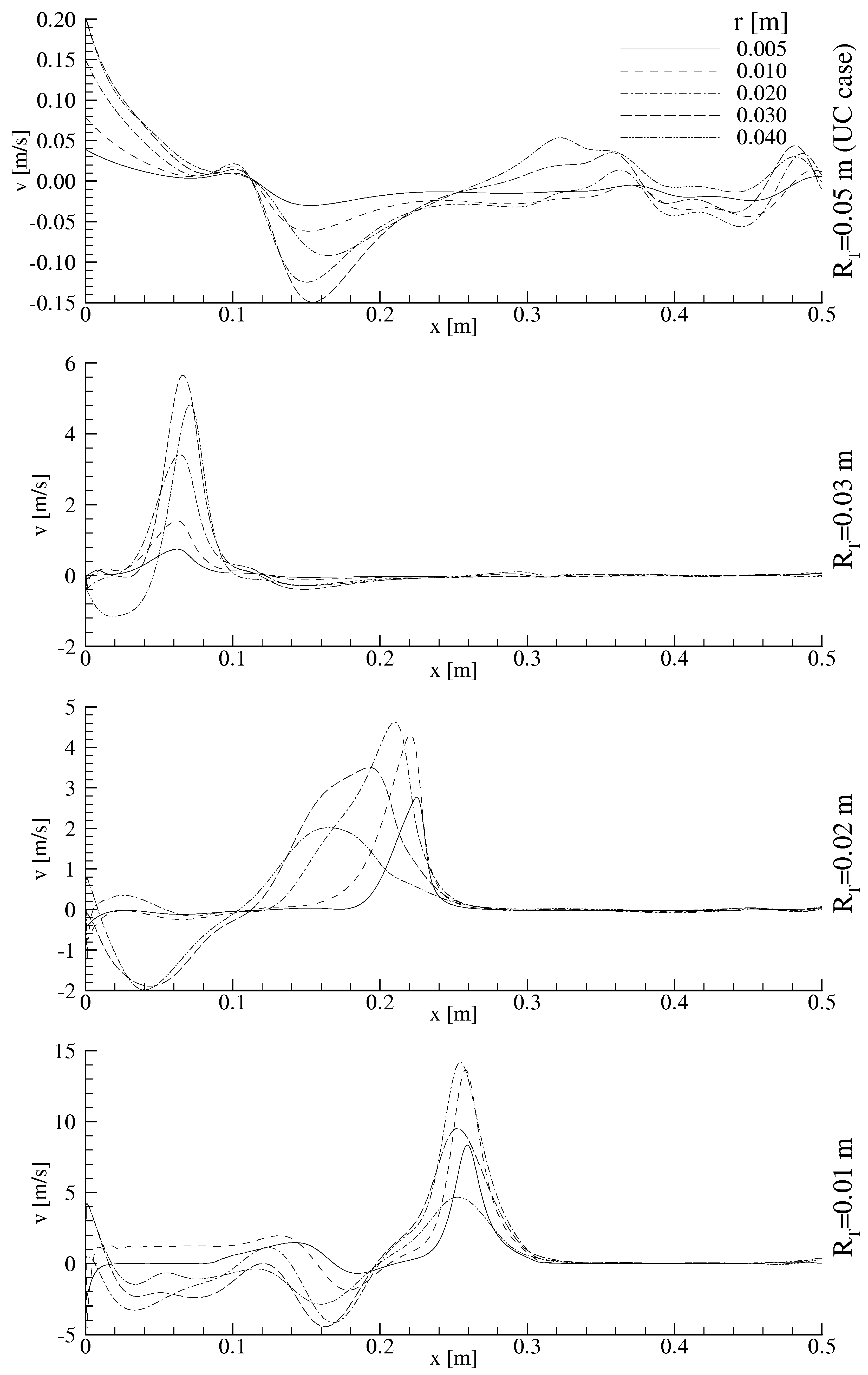
As known, in a pipe flow, the cross-section contraction accelerates fluid, and the sudden expansion in the pipe produces the high velocity gradients which also increase the local entropy generation rate (see Eqs (3e), (6a) and (6c)). In order to see clearly these gradients, the variations of the axial and radial velocities at the various radial planes in the uniform section are plotted versus the axial distance in Figure 3 and Figure 4 for the cases mentioned in the previous paragraph, respectively. The effect of the contraction of the throat cross-section on the velocity distribution can be determined in these figures. At the pipe wall, both velocities are zero along the pipe length (see Eqs.(5f,h)). As the throat radius contracts from 0.03 to 0.01m, the region, in which the high velocity gradients occurs, expands up to a certain distance, in the range of x=0.1 to 0.3 m, at the axial direction. The both velocities remain quasi-constant along the pipe length after these distances.

The Local Entropy Generation in the Uniform Section

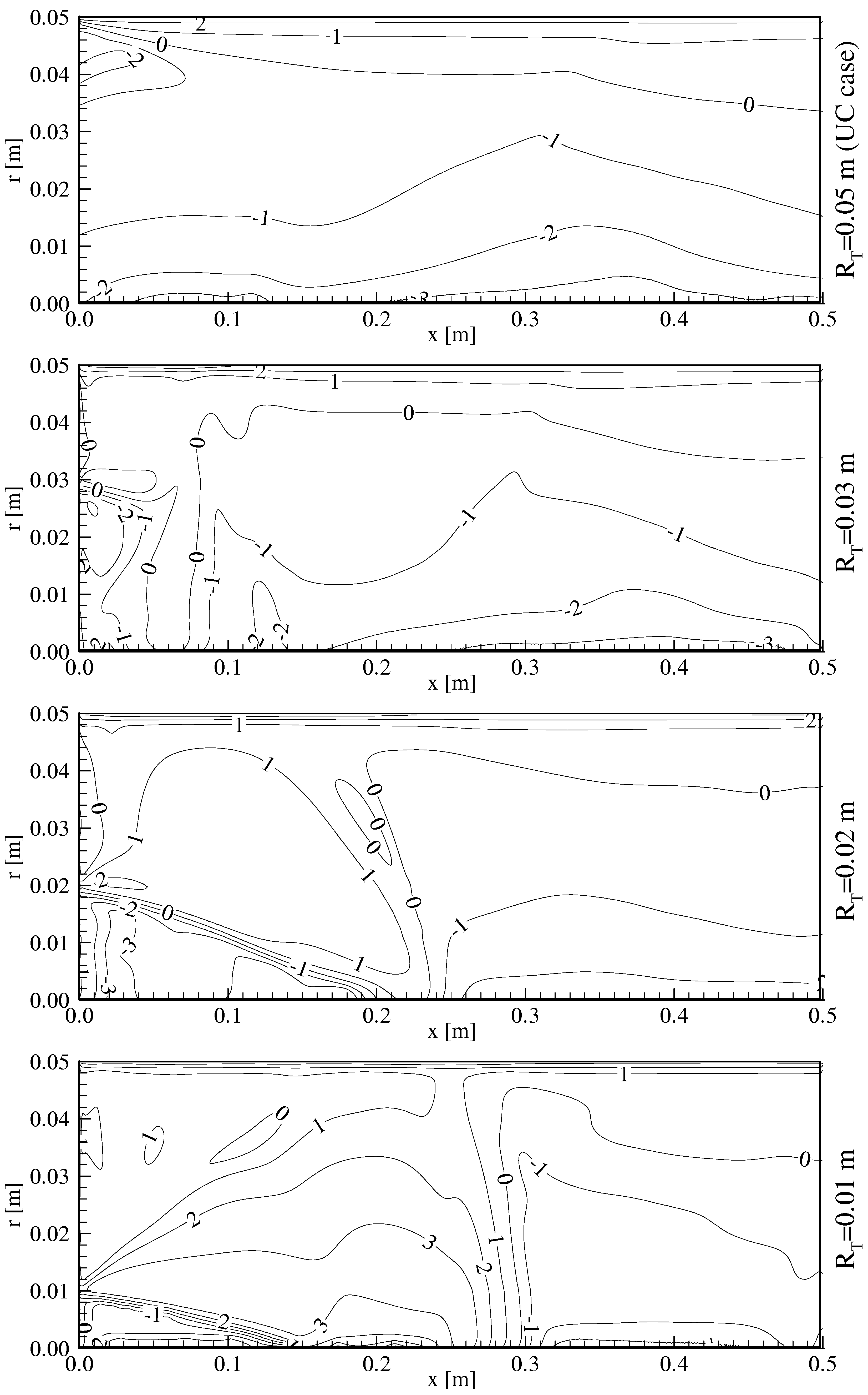
The volumetric local entropy generation rate distributions within the uniform section of the pipe in the case of Tin=400 K, φmax=5 kg/m2-s and hamb=20 W/m2-K are countered in Figure 5 as logarithmic values for the different throat radiuses (RT=0.05, 0.03, 0.02 and 0.01 m). These contours do not follow the temperature contours presented in Figures 2. This is because of the entropy generation is proportional to the temperature gradient and inverse proportional to the temperature. As the cool penetration takes place along the pipe length, the local entropy generation region widens but the peak value of volumetric local entropy generation rate decreases. In region near the wall, the volumetric local entropy generation rate profiles remain quasi-constant along the pipe length. However, it is very close to zero along the centerline due to the fact that the radial temperature gradient is zero and the velocity gradients are either very small or zero. The contraction of the radius of the throat (RT=0.05 to 0.01 m) increases significantly the entropy generation rate, i.e.: its maximum value rises from 2.83 to 4.63 W/m3-K (as the logarithmic value) (about 60%).
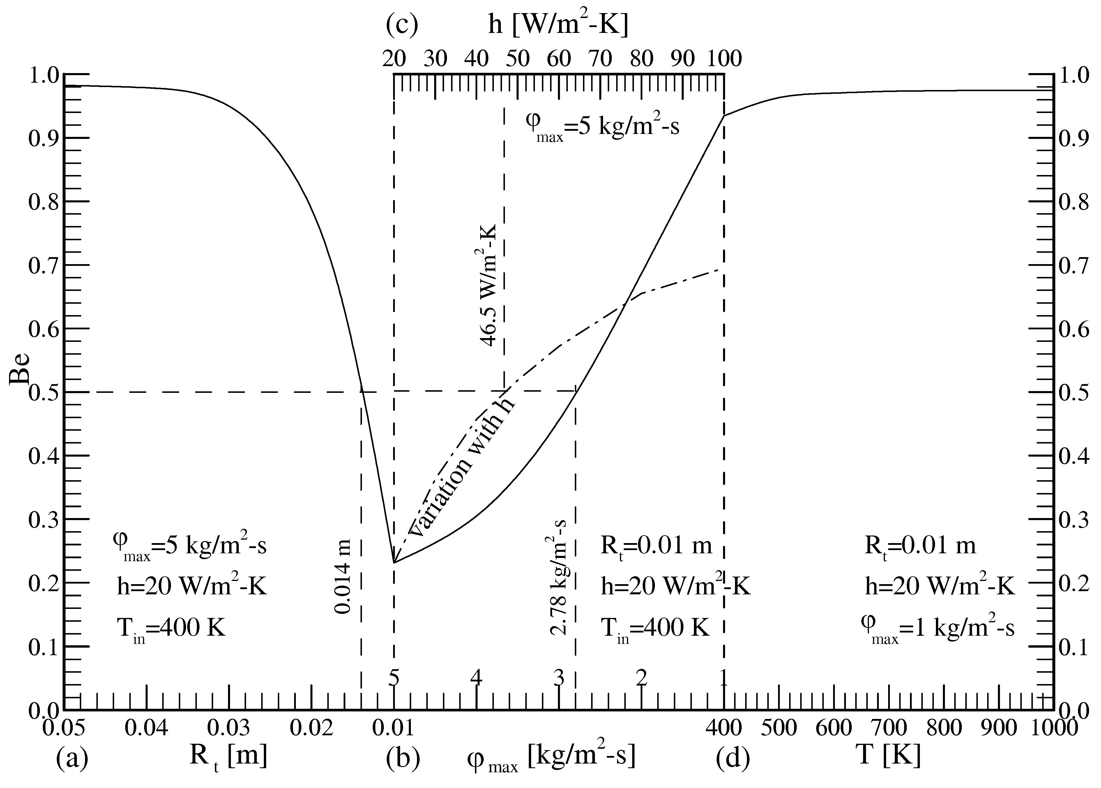
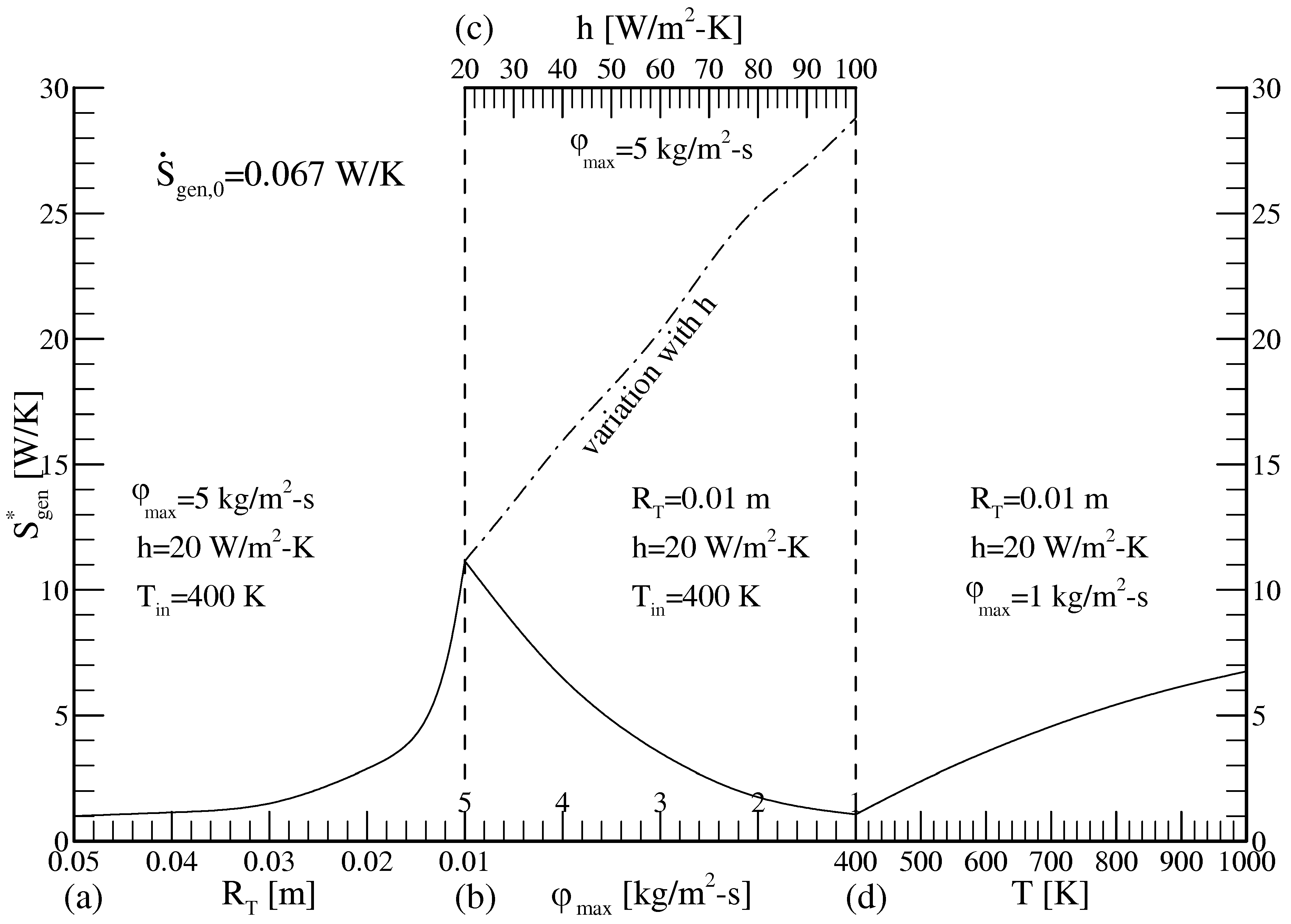
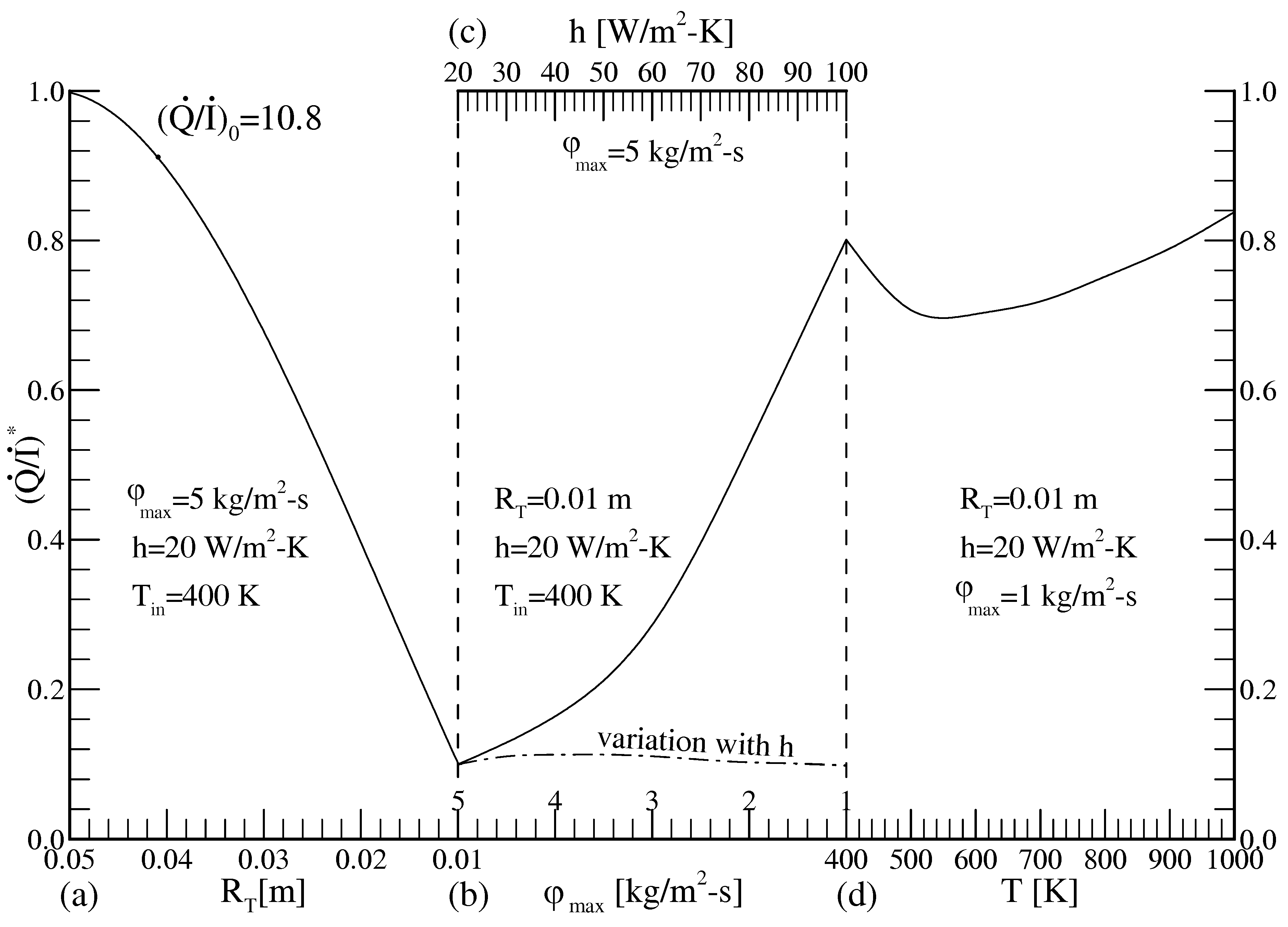
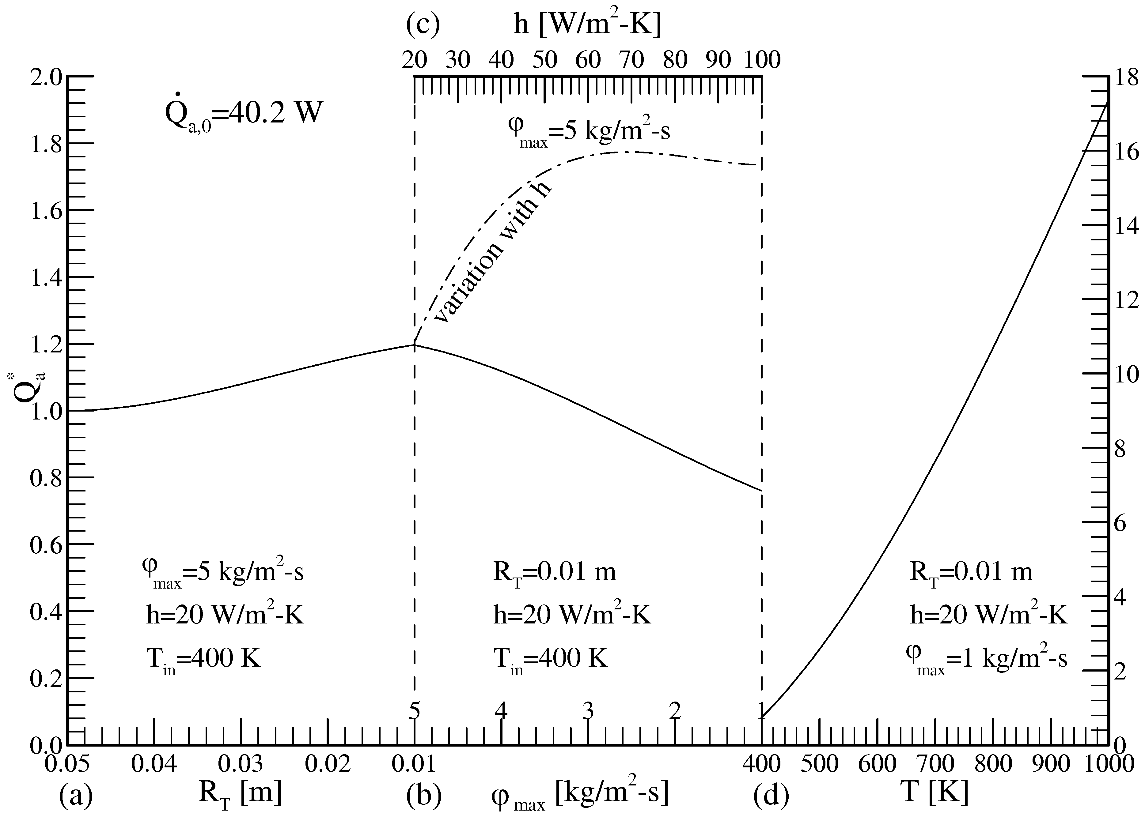
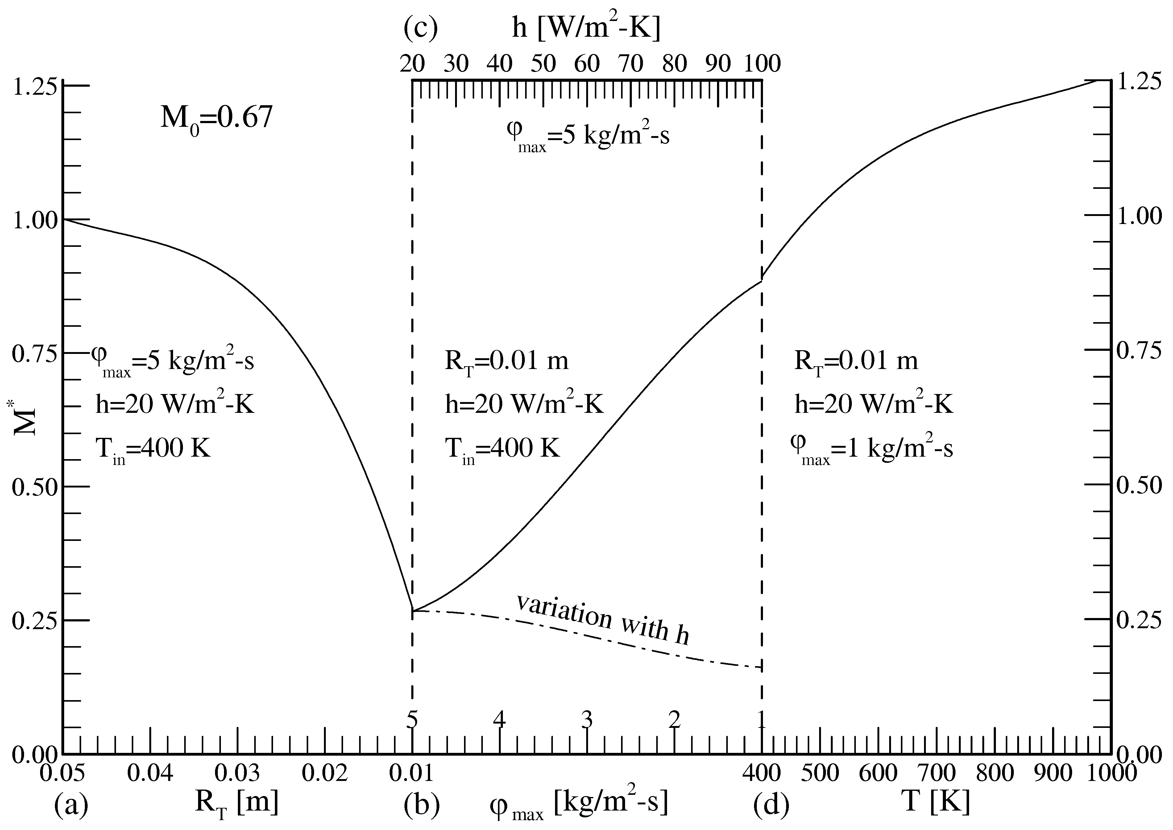
Figure 6, Figure 7, Figure 8, Figure 9 and Figure 10, including four each sub-graphics, show the variations of the Bejan number, the normalized total entropy generation (S*gen), the normalized ratio of the heat transfer to the irreversibility generated (Q/I)*, the normalized exergy transfer rate (Q*a) and the normalized merit number (M*), respectively, with the different parameters: (a) the throat radius (RT=0.05 to 0.01 m), (b) the maximum mass flux (φmax=5 to 1 kg/m2-s), (c) the ambient heat transfer coefficient (hamb=20 to 100 W/m2-K) and (d) the inlet temperature (Tin=400 to 1000 K).
The values of the throat radius, maximum mass flux and ambient heat transfer coefficient, (RT=0.014 m, φmax=2.78 kg/m2-s and h=46.5 W/m2-K), corresponding to Be=0.5, in which the heat transfer and fluid friction entropy generation rates are equal to the each other, are also indicated in the sub-graphics 6a,b,c. As the throat cross-section contracts, the Bejan number first declines slightly and then decreases sharply to 0.23 (after RT=0.03 m). This means that the cross-section contraction increases significantly the fluid friction entropy generation rate rather than the heat transfer entropy generation rate. However, the Bejan number rises exponentially from 0.23 to 0.94 as the maximum mass flux decreases linearly from 5 to 1 kg/m2-s, and its rise continues slightly from 0.94 to 0.97 with the increase of the inlet temperature from 400 to 1000 K. Due to the fact that the increment in the ambient heat transfer coefficient increases the heat transfer from the fluid to the surrounding, which in turn raises significantly the heat transfer entropy generation, it also raises the Bejan number (from 0.23 to 0.69).
As is apparent from Figure 7, the contraction in the throat cross-section increases the fluid friction entropy generation rate, which in turn increases exponentially 11 times the total entropy generation rate with respect to the its base value. However, this rate decreases exponentially to 1.07 (the normalized value) as the maximum mass flux decreases linearly. Furthermore, as expected, it rises quasi-linearly from 1.07 to 6.8 and from 11 to 28.8 with the increases of the inlet temperature and the ambient heat transfer coefficient, respectively, due to the fact that these increases raise the heat transfer entropy generation rate. Figure 8 shows the normalized ratio of the heat transfer to the irreversibility ( Q ˙ / I ˙ ), which is inverse proportional to the total entropy generation rate. As the throat cross-section contracts, it declines due to the increase of the fluid friction irreversibility. However, it rises from 0.1 to 0.8 with the decrease of the maximum mass flux. This ratio is not very much affected from the ambient heat transfer coefficient whereas with the increase of the inlet temperature, it first decreases until Tin=540 K and then increases quasi-linearly to 0.84. These results bring out that the cross-section contraction lowers the ratio of the heat transfer to the irreversibility in all investigated cases.
The exergy transfer rate and the merit number are one of the important parameters in the entropy generation analyses. Figure 9 and Figure 10 exhibit their normalized variations. As the cross-section contracts, the exergy transfer rate increases slightly 1 to 1.2, and decreases from this level to 0.76 with the decrease of the maximum mass flux. This rate rises quasilogarithmically from 1.2 to 1.74 and quasi-linearly from 0.76 to 17.4 also with the increases of the ambient heat transfer coefficient and the inlet temperature, respectively, due to the fact that both increases (especially the inlet temperature increase) raise significantly the heat transfer. The normalized merit number profiles in the same cases except the temperature increase exhibit a contrary situation of the normalized exergy transfer rate, i.e.: they decrease 73% (from 1 to 0.27) and 40% (from 0.27 to 0.16) with the contraction of the cross-section and with the increase of the ambient heat transfer coefficient, respectively, and rise 226% (from 0.27 to 0.88) and 43% (from 0.88 to 1.26) with the decrease of the maximum mass flux and with the increase of the inlet temperature, respectively. These values indicate that the useful energy transfer rate to irreversibility rate improves as the mass flux decreases and as the inlet temperature increases.

Conclusions

The numerical solution of the local entropy generation in the compressible flow through the suddenly expanding pipe was analyzed for the different expansion ratios. The effects of the mass flux, the ambient heat transfer coefficient and the inlet temperature on the entropy generation rate were also investigated. The specific conclusions derived from this study can be listed briefly as follows:
  • In the case of Tin=400 K, φmax=5 kg/m2-s and hamb=20 W/m2-K, the heat transfer from the pipe wall to the environment increases from 216 to 238 W as the throat radius contracts from 0.05 to 0.01 m.
  • As the throat radius contracts from 0.03 to 0.01m, the high velocity gradient region expands up to a certain distance, in the range of x=0.1 to 0.3 m, at the axial direction and the both axial and radial velocities remain quasi-constant along the pipe length after these distances.
  • The contraction of the radius of the throat (from 0.05 to 0.01 m) increases significantly the maximum value of the volumetric entropy generation rate, (about 60%).
  • The contraction in the throat cross-section raises exponentially 11 times the total entropy generation rate with respect to the its base value. Furthermore, it rises quasilinearly from 1.07 to 6.8 and from 11 to 28.8 with the increases of the inlet temperature and the ambient heat transfer coefficient, respectively.
  • The normalized merit number decreases 73% and 40% with the contraction of the cross-section and with the increase of the ambient heat transfer coefficient (from 20 to 100 W/m2-K), respectively, whereas it rises 226% and 43% with the decrease of the maximum mass flux (from 5 to 1 kg/m2-s) and with the increase of the inlet temperature (from 400 to 1000 K), respectively. Consequently, the useful energy transfer rate to irreversibility rate improves as the mass flux decreases and as the inlet temperature increases.

References

  1. Macagno, E. O.; Hung, T. K. Computation and experimental study of a captive annular eddy. J. Fluid Mech. 1967, 28, 43–64. [Google Scholar] [CrossRef]
  2. Fletcher, D.; Maskel, S.; Patrick, M. Heat and mass transfer computations for laminar flow in an axisymmetric sudden expansion. Computers Fluids 1985, 13, 207. [Google Scholar] [CrossRef]
  3. Khezzar, L.; Whitelaw, J. H.; Yianneskis, M. An experimental study of round sudden expansion flows. Proc. 5th Symposium on turbulent Shear Flows 1985, Cornell University. 5–25. [Google Scholar]
  4. Stieglmeier, M.; Tropea, C.; Weiser, N.; Nitsche, W. Experimental investigation of the flow through axisymmetric expansions. J. Fluids Eng. 1989, 111, 464–471. [Google Scholar] [CrossRef]
  5. Oliveira, P.J.; Pinho, F.T.; Schulte, A. A general correlation for the local loss coefficient in newtonian axisymmetric sudden expansions. International Journal of Heat and Fluid Flow 1998, 19, 655–660. [Google Scholar] [CrossRef]
  6. Boughamoura, A.; Belmabrouk, H.; Nasrallah, S. B. Numerical study of a pistondriven laminar flow and heat transfer in a pipe with a sudden expansion. International Journal of Thermal Sciences 2003, 42, 591–604. [Google Scholar] [CrossRef]
  7. Neofytou, P.; Drikakis, D. Non-newtonian flow instability in a channel with a sudden expansion. J. Non-Newtonian Fluid Mech. 2003, 111, 127–150. [Google Scholar] [CrossRef]
  8. Poole, R.J.; Escudier, M.P. Turbulent Flow of Viscoelastic Liquids through an Axisymmetric Sudden Expansion. J. Non-Newtonian Fluid Mech. 2004, 117, 25–46. [Google Scholar] [CrossRef]
  9. Mukherjee, P.; Biswas, G.; Nag, P.K. Second-law analysis of heat transfer in swirling flow through a cylindrical duct. ASME Journal of Heat Transfer 1987, 109, 308–313. [Google Scholar] [CrossRef]
  10. Bejan, A. Entropy Generation Minimization; CRC Press: New York, 1996. [Google Scholar]
  11. Bejan, A. Entropy minimization: the new thermodynamics of finite-size devices and finite-time processes. J. Appl. Phys. 1996, 79, 1191–1218. [Google Scholar] [CrossRef]
  12. Sahin, A. Z. Second law analysis of laminar viscous flow through a duct subjected to constant wall temperature. ASME Journal of Heat Transfer 1998, 120, 76–83. [Google Scholar] [CrossRef]
  13. Sahin, A. Z. A second law comparison for optimum shape of duct subjected to constant wall temperature and laminar flow. Heat Mass Transfer 1998, 33, 425–430. [Google Scholar]
  14. Sahin, A. Z. Irreversibilities in various duct geometries with constant wall heat flux and laminar flow. Energy 1998, 23(6), 465–473. [Google Scholar] [CrossRef]
  15. Sahin, A. Z. Effect of variable viscosity on the entropy generation and pumping power in a laminar fluid flow through a duct subjected to constant heat flux. Heat Mass Transfer 1999, 35, 499–506. [Google Scholar]
  16. Sahin, A. Z. Entropy generation in turbulent liquid flow through a smooth duct subjected to constant wall temperature. Int. Journal of Heat and Mass Transfer 2000, 43, 1469–1478. [Google Scholar] [CrossRef]
  17. Sahin, A. Z. Entropy generation and pumping power in a turbulent fluid flow through a smooth pipe subjected to constant heat flux. Exergy, An International Journal 2002, 2, 314–321. [Google Scholar] [CrossRef]
  18. Shuja, S.Z.; Yilbas, B.S.; Budair, M.O.; Hussaini, I.S. Entropy analysis of a flow past a heat-generated bluff body. Int. J. Energy Research 1999, 23, 1133–1142. [Google Scholar] [CrossRef]
  19. Shuja, S.Z.; Yilbas, B.S.; Iqbal, M.O.; Budair, M.O. Flow through a protruding bluff body–heat and irreversibility analysis. Exergy An International Journal 2001, 1(3), 209–215. [Google Scholar] [CrossRef]
  20. Yilbas, B.S.; Shuja, S.Z.; Budair, M.O. Second law analysis of a swirling flow in a circular duct with restriction. Int. Journal of Heat and Mass Transfer 1999, 42, 4027–4041. [Google Scholar] [CrossRef]
  21. Yilbas, B.S.; Yurusoy, M.; Pakdemirli, M. Entropy analysis for Non-Newtonian fluid flow in annular pipe:Constant viscosity case. Entropy 2004, 6, 304–315. [Google Scholar] [CrossRef]
  22. Demirel, Y.; Kahraman, R. Entropy generation in a rectangular packed duct with wall heat flux. Int. Journal of Heat and Mass Transfer 1999, 42, 2337–2344. [Google Scholar] [CrossRef]
  23. Hyder, S.J.; Yilbas, B.S. Entropy analysis of conjugate heating in a pipe flow. Int. J. Energy Research 2002, 26, 253–262. [Google Scholar] [CrossRef]
  24. Abbassi, H.; Magherbi, M.; Brahim, A.B. Entropy generation in Poiseuille–Benard channel flow. International Journal of Thermal Sciences 2003, 42, 1081–1088. [Google Scholar] [CrossRef]
  25. Mahmud, S.; Fraser, R.A. Thermodynamic analysis of flow and heat transfer inside channel with two parallel plates. Exergy An International Journal 2002, 2, 140–146. [Google Scholar] [CrossRef]
  26. Mahmud, S.; Fraser, R.A. The second law analysis in fundamental convective heat transfer problems. International Journal of Thermal Sciences 2003, 42, 177–186. [Google Scholar] [CrossRef]
  27. Shuja, S.Z.; Yilbas, B.S.; Budair, M.O. Local entropy generation in an impinging jet: minimum entropy concept evaluating various turbulence models. Computer Methods in Applied Mechanics and Engineering 2001, 190, 3623–3644. [Google Scholar] [CrossRef]
  28. Shuja, S.Z.; Yilbas, B.S. A laminar swirling jet impingement on to an adiabatic wall Effect of inlet velocity profiles. International Journal of Numerical Methods for Heat & Fluid Flow 2001, 11, 237–254. [Google Scholar]
  29. Shuja, S.Z.; Yilbas, B.S.; Budair, M.O. Investigation into a confined laminar swirling jet and entropy production. Int. J. Numerical Methods for Heat & Fluid Flow 2002, 12, 870–887. [Google Scholar]
  30. Shuja, S.Z.; Yilbas, B.S.; Rashid, M. Confined swirling jet impingement onto an adiabatic wall. International Journal of Heat and Mass Transfer 2003, 46, 2947–2955. [Google Scholar] [CrossRef]
  31. Al-Zaharnah, I.T.; Yilbas, B.S. Thermal analysis in pipe flow:Influence of variable viscosity on entropy generation. Entropy 2004, 6, 344–363. [Google Scholar] [CrossRef]
  32. Abu-Hijleh, B.A/K.; Abu-Qudais, M.; Abu Nada, E. Numerical prediction of entropy generation due to natural convection from a horizontal cylinder. Energy 1999, 24(4), 327–333. [Google Scholar] [CrossRef]
  33. Haddad, O. M.; Alkam, M. K.; Khasawneh, M. T. Entropy generation due to laminar forced convection in the entrance region of a concentric annulus. Energy 2004, 29(1), 35–55. [Google Scholar] [CrossRef]
  34. Yapıcı, H.; Kayataş, N.; Albayrak, B.; Baştürk, G. Numerical calculation of local entropy generation in a methane-air burner. Energy Conversion and Management. in press.
  35. Yapıcı, H.; Baştürk, G.; Kayataş, N.; Yalçın, Ş. Numerical study on transient local entropy generation in pulsating turbulent flow through an externally heated pipe. SADHANA. (submitted).
  36. Yapıcı, H.; Kayataş, N.; Baştürk, G.; Kahraman, N. Study on transient local entropy generation in pulsating fully developed laminar flow through an externally heated pipe. Heat and Mass Transfer. (submitted).
  37. Fluent Incorporated. FLUENT User’s guide version 6.1. 2003. [Google Scholar]
  38. Yakhot, V.; Orszag, S.A. Renormalization Group Analysis of Turbulence: I. Basic Theory. Journal of Scientific Computing 1986, 1(1), 1–51. [Google Scholar] [CrossRef]
  39. Choudhury, D. Introduction to the Renormalization Group Method and Turbulence Modeling. Fluent Inc. Technical Memorandum 1993, TM-107. [Google Scholar]
  40. Kadoya, K.; Matsunaga, N.; Nagashima, A. Viscosity and thermal conductivity of dry air in the gaseous phase. J. Phys. Chem. Ref. Data 1985, 14(4), 947–970. [Google Scholar] [CrossRef]
  41. Jacobsen, R.T.; Penoncello, S.G.; Breyerlein, S.W.; Clark, W.P.; Lemmon, E.W.A. Thermodynamic property formulation for air. Fluid Phase Equilibria 1992, 79, 113–124. [Google Scholar] [CrossRef]
  42. Lemmon, E.W.; Jacobsen, R.T.; Penoncello, S.G.; Friend, D.G. Thermodynamic properties of air and mixtures of nitrogen, argon, and oxygen from 60 to 2000 K at pressures to 2000 MPa. J. Phys. Chem. Ref. Data 2000, 29(3), 331–385. [Google Scholar] [CrossRef] [Green Version]
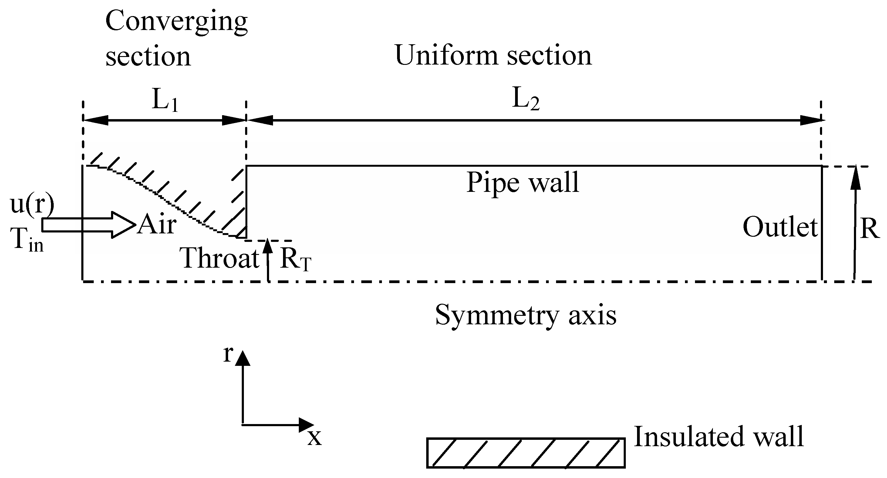
Figure 1. Coordinate system and two-dimensional axisymmetric model of the suddenly expanding pipe (the dimensions are not in scale)
Entropy 07 00038 g001
Figure 2. Temperature contours within the uniform section of the pipe (Tin=400 K, φmax=5 kg/m2-s and hamb=20 W/m2-K)
Entropy 07 00038 g002
Figure 3. Variations of axial velocities at the various radial planes in the uniform section of the pipe (Tin =400 K, φmax=5 kg/m2-s and hamb=20 W/m2-K)
Entropy 07 00038 g003
Figure 4. Variations of radial velocities at the various radial planes in the uniform section of the pipe (Tin =400 K, φmax=5 kg/m2-s and hamb=20 W/m2-K)
Entropy 07 00038 g004
Figure 5. Logarithmic volumetric local entropy generation rate contours within the uniform section of the pipe (Tin =400 K, φmax=5 kg/m2-s and hamb=20 W/m2-K)
Entropy 07 00038 g005
Figure 6. Variations of the Bejan number with (a) the throat radius, (b) the maximum mass flux, (c) the ambient heat transfer coefficient and (d) the inlet temperature
Entropy 07 00038 g006
Figure 7. Variations of the normalized total entropy generation with (a) the throat radius, (b) the maximum mass flux, (c) the ambient heat transfer coefficient and (d) the inlet temperature
Entropy 07 00038 g007
Figure 8. Variations of the normalized ratio of the heat transfer to the irreversibility generated in the system ( Q ˙ / I ˙ )* with (a) the throat radius, (b) the maximum mass flux, (c) the ambient heat transfer coefficient and (d) the inlet temperature
Entropy 07 00038 g008
Figure 9. Variations of the normalized exergy transfer rate with (a) the throat radius, (b) the maximum mass flux, (c) the ambient heat transfer coefficient and (d) the inlet temperature
Entropy 07 00038 g009
Figure 10. Variations of the normalized merit number with (a) the throat radius, (b) the maximum mass flux, (c) the ambient heat transfer coefficient and (d) the inlet temperature
Entropy 07 00038 g010