
Chaos Synchronization of Integrated Five-Section Semiconductor Lasers
by
 ,
,
Yuanyuan Guo
1,2,*,
Yao Du
1,2,
Hua Gao
3,
Min Tan
1,2,
Tong Zhao
1,2 ,
,
Zhiwei Jia
1,2,
Pengfa Chang
1,2 and
Longsheng Wang
1,2 1
Key Laboratory of Advanced Transducers and Intelligent Control System, Ministry of Education and Shanxi Province, Taiyuan 030024, China
2
College of Electronic Information and Optical Engineering, Taiyuan University of Technology, Taiyuan 030024, China
3
College of Information Engineering, Shanxi Vocational University of Engineering Science and Technology, Taiyuan 030024, China
*
Author to whom correspondence should be addressed.
Entropy 2024, 26(5), 405; https://doi.org/10.3390/e26050405
Submission received: 25 March 2024
/
Revised: 2 May 2024
/
Accepted: 4 May 2024
/
Published: 6 May 2024
Abstract
:We proposed and verified a scheme of chaos synchronization for integrated five-section semiconductor lasers with matching parameters. The simulation results demonstrated that the integrated five-section semiconductor laser could generate a chaotic signal within a large parameter range of the driving currents of five sections. Subsequently, chaos synchronization between two integrated five-section semiconductor lasers with matched parameters was realized by using a common noise signal as a driver. Moreover, it was found that the synchronization was sensitive to the current mismatch in all five sections, indicating that the driving currents of the five sections could be used as keys of chaotic optical communication. Therefore, this synchronization scheme provides a candidate to increase the dimension of key space and enhances the security of the system.
1. Introduction
Chaotic optical communication has attracted much attention because of its fast transmission rate [1,2,3,4], capacity for long-distance communication [5,6] and compatibility with current fiber-optic network communications [7,8,9]. For instance, in 2005, Argyris et al. realized a metropolitan area network trial with a rate of 1 Gb/s and a communication distance of 120 km in Athens [7]. In 2010, Argyris et al. realized 100 km, 2.5 Gb/s chaotic optical communication using a photonic integrated chaotic laser [10]. In 2018, Yi et al. realized 100 km, 30 Gb/s chaotic optical communication using chaotic optoelectronic oscillators [2]. External cavity feedback semiconductor lasers are the most commonly used transceivers in chaotic optical communications because of their simple structure and flexible operation [11]. Externally controllable hardware parameters such as bias current, feedback strength and external cavity feedback length of external cavity feedback semiconductor lasers can be used as a key for chaotic optical communication. However, the outer cavity feedback length can be obtained by autocorrelation or mutual information calculation of the timing waveforms. The relaxation oscillation frequency of the laser can be determined by analyzing the spectrum of the chaotic signal, and then the corresponding bias current can be estimated [12]. As a result, in this communication system, the number of hardware parameters that can be used as key parameters is smaller, the key space of chaotic optical communication is insufficient, and its security is threatened.
Therefore, in recent years, a large number of key space enhancement schemes to enhancing the key space of the chaotic optical communication have been proposed. For instance, in 2009, Xia et al. proposed that the time-delay feature can be suppressed by two external cavities [13]; thus, the cavity length can be used as a key parameter and the key space can be enhanced. In 2016, Yi et al. introduced 16 cascaded standard fixtures in an optoelectronic feedback loop to suppress the time-delay information and increased the key space of the system to 1048 by taking the center frequencies of the standard fixtures as additional key parameters [14]. In 2019, Wang et al. numerically demonstrated that external feedback-based chirped fiber Bragg grating (CFBG) can eliminate the time-delay feature, and the dispersion and center frequency of the CFBG were introduced as key parameters, increasing the key space to 244 [15]. Jiang et al. enhanced key space by modulating the phase of the feedback light using a pseudo-random code sequence with a code length of 27 [16]. Ji et al. proposed a scheme of secondary encryption to increase the dimensionality of key parameters, realizing the enhancement of the key space for chaotic communication [17].
In this paper, we propose a scheme of chaos synchronization between two integrated five-section semiconductor lasers (IFSSL) and model the simulation study in the commercial software program VPItransmissionMaker. The IFSSL is composed of two distributed feedback laser sections (DFB1 and DFB2), two phase sections (P1 and P2) and an amplification section (A). We investigate the effects of the driving currents of the five sections on the output dynamic characteristics and determine the parameter range to generate chaotic driving currents, and their mismatch on the synchronization coefficients is studied in detail, proving that the synchronization is sensitive to the mismatching of the driving currents. Predictably, in the chaotic optical communication system based on IFSSL, the driving currents of all five sections of IFSSL can be used as the key parameter, which increases the dimension of the key space and enhances the key space of the system.
2. Materials and Methods
Figure 1 shows the schematic diagram of the chaos synchronization of two IFSSLs. The broadband noise signal generated by the super-luminescent diode (SLD) is transmitted unidirectionally through an optical isolator (OI) and then filtered by a low-pass filter (LPF). Through a 3 dB optical coupler (OC), the broadband noise signal is split into two paths which are, respectively, injected into the IFSSLA and IFSSLB at the legitimate communication parties, Alice and Bob. The injection powers of IFSSLA and IFSSLB are varied by private variable optical attenuators (VOAs). The output of the IFSSL is filtered by a low-pass filter (LPF) and divided into two paths through the OC (optical coupler); one path is directly detected, optical spectra are captured by an optical spectrum analyzer (OSA), and the other path is converted into an electrical signal by the photodetector (PD), which views and captures the R-F spectrum, with an electrical spectrum analyzer (ESA), and the temporal waveform of the signal, with an oscilloscope (OSC). The IFSSL is composed of two distributed feedback laser sections (DFB1 and DFB2), two phase sections (P1 and P2) and an amplification section (A). The P1 section is used to change the coupling phase between DFB1 and DFB2; the P2 and A sections are used to generate active optical feedback, which the P2 section uses to change the feedback phase of the optical feedback, and the A section is used to provide gain and change the intensity of the feedback light. The five sections are driven by individual currents. Table 1 shows the main internal design parameters of the IFSSL.
3. Results
3.1. Dynamic Characterization of IFSSL
Figure 2 shows the temporal waveforms, optical spectra and radio frequency (R-F) spectra of the output signal of IFSSL under various IP1 values, when IDFB1 = 60 mA, IDFB2 = 66 mA and IP2 = IA = 0 mA. As shown as Figure 2(a1–a3), when IP1 = 9 mA, the IFSSL output is a single-mode signal whose center wavelength matches the main mode of the DFB2 laser λ2a (λ2a = 1557.989 nm). The temporal waveform is almost a constant with small ripples, and the R-F spectrum exhibits oscillations which are similar to noise. Thus, the IFSSL is currently in a stable state. When IP1 increases to 12 mA, the IFSSL generate a dual-mode signal, indicating a period-one state, as shown in Figure 2(b2), in which a composite cavity mode [18,19,20] λ2b appears close to λ2a. Furthermore, as shown in Figure 2(b1,b3), the corresponding temporal waveform shows a single-period oscillation trace, and the R-F spectrum displays significant peaks at the frequencies corresponding to the composite, f, and its higher harmonics, f. When IP1 further increases to 15 mA, the IFSSL shifts to a quasi-periodic state, as shown in Figure 2(b3); in addition, at the wavelengths λ2a and λ2b, the wavelength of λ1 is lased. The temporal waveform in Figure 2(c1) exhibits multi-period oscillation, and the R-F spectrum in Figure 2(c3) presents multiple frequency components f, 2f, fa (frequency detuning of λ1 and λ2a), fb (frequency detuning of λ1 and λ2b) and f − fa. When IP1 = 17 mA, the IFSSL generates chaotic signal, as shown in Figure 2(d1–d3), the optical spectra and the R-F spectrum are broadened, and the temporal waveform shows large and irregular magnitude variations.
Figure 3 shows a diagram of the dynamic states of the IFSSL in the parameter space IDFB2 and IP1 when IP2 = IA = 0 mA and IDFB1 = 60 mA. Different colors denote different dynamical states. By varying IDFB2 and IP1, the IFSSL can generating a variety of dynamical states, such as a steady state (S), a period-one state (P1), a quasi-periodic state (QP) and chaos (C). When 43 mA < IDFB2 < 100 mA, 0 mA < IP1 < 30 mA, as shown in Figure 3, the IFSSL is mainly in chaos (C) and a steady state (S). Moreover, a quasi-periodic (QP) state occurs less frequently, and a period-one (P1) state occurs in the smallest range. It can be observed from the map that the IFSSL is capable of outputting a chaotic signal over a wide parameter range of driving currents of IDFB2 and IP1.
In order to comprehensively analyze the effect of the driving current of the feedback loop, we select four points a, b, c, d in Figure 3 to study the output state of the IFSSL under different IP2 and IA when the IFSSL in four different states. The diagram of the dynamic state is shown in Figure 4. When the IFSSL is initially at point a, the original steady state rapidly switches to a period-one state, a quasi-periodic state or a chaotic state as the IP2 and IA vary. As shown as Figure 4a, the quasi-periodic state occupies the major portion, the chaotic state and the period-one state occupies the minor portion, and the steady state occupies the smallest portion. When the IFSSL is initially in a period-one state at point b, as shown in Figure 4b, the range of the chaotic state and period-one state portions expand and those of the steady state and quasi-periodic state portions narrow compared with Figure 4a. The steady state disappears in Figure 4c when the IFSSL is initially in a quasi-periodic state at point c. The period-one state occupies a small portion, and the quasi-periodic state and chaotic state still occupy a major portion, in which the range of the chaotic state further expands compared with Figure 4a,b. The initially chaotic state of IFSSL at point d changes to a quasi-periodic state and a period-one state in certain areas as the IP2 and IA are adjusted. As the results in Figure 4d show, the range of the chaotic state is largest in Figure 4a–d, and the range of the quasi-periodic state is close to that of a chaotic state. In conclusion, the IFSSL can always generate a chaotic signal when the IP2, IA, IDFB2 and IP1 vary.
3.2. Chaos Synchronization of IFSSL
Chaos synchronization is prerequisite for chaotic secure communication. In this scheme, the chaos synchronization between two responses IFSSLA and IFSSLB with identical parameters is achieved using a broadband noise signal generated from the SLD as the common driving signal. Figure 5 shows the temporal waveforms of the SLD, the response IFSSLA and IFSSLB and the corresponding correlation plots of SLD and IFSSLA and between IFSSLA and IFSSLB. The power of SLD is 30.18 mW, and the currents of IFSSLA and IFSSLB both are set as IDFB1 = 60 mA, IP1 = 26 mA, IDFB2 = 77 mA, IP2 = 15 mA and IA = 15 mA. Figure 5a shows that the chaotic temporal waveforms of IFSSLA and IFSSLB are mostly identical, the corresponding scatter plots in Figure 5b exhibit a linear distribution, and the correlation coefficient reaches 0.9742. Figure 5c shows the temporal waveforms of the SLD and IFSSLA, which have no obvious similarities. The scattered distribution in Figure 5d also proves that the correlation between SLD and IFSSL is very low, and the correlation coefficient is calculated as 0.3868. The high-quality synchronization between the two responses lasers benefits the low error decoding of message, while the low correlation between SLD and IFSSLA ensures the security of the communication system by preventing eavesdroppers from obtaining carrier-correlated informationvia a public link.
The effects of the power of SLD on the synchronization quality of IFSSLA and IFSSLB when the IDFB1, IDFB2 and IA have different values are shown in Figure 6. For all three cases, as the driving power increases, the correlation coefficient of the IFSSLA and IFSSLB increases, and when the driving power is larger than about 30 mW, high-quality chaos synchronization (CC > 0.9) can be achieved. As the driving current IDFB1 in Figure 6a increases, the power coupled into the DFB2 region from the DFB1 region increases, and thus the driving power required to achieve high-quality synchronization slightly decreases. With the increase of the drive current IDFB2 and IA, as shown in Figure 6b,c, the output power of the laser DFB2 increases, and thus the drive power required to achieve high-quality chaos synchronization slightly increases.
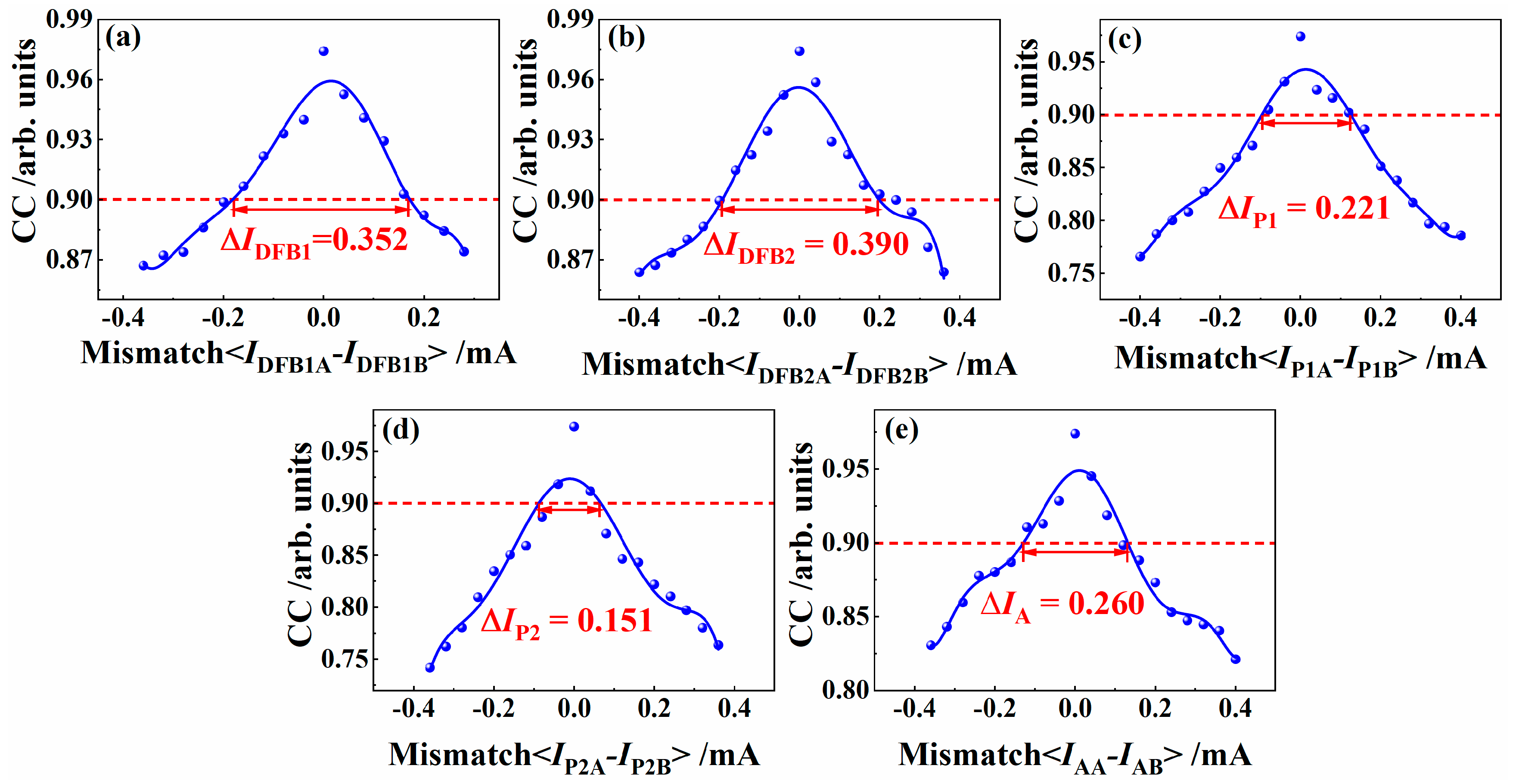
On the basis of the high-quality chaos synchronization of IFSSLA and IFSSLB described above, we investigate the effects of the mismatching of the driving current IDFB1, IDFB2, IP1, IP2 and IA on the synchronization coefficient of IFSSLA and IFSSLB. Figure 7 shows that the synchronization performance of the system becomes degradative as the current mismatch increases, but the effect of individual current mismatches on the synchronization performance is different. When the synchronization of the system decreases to the threshold value of 0.90, the mismatch ranges of IDFB1, IP1, IDFB2, IP2 and IA are 0.297 mA, 0.334 mA, 0.193 mA, 0.122 mA and 0.226 mA, respectively. This indicates that the synchronization performance of the system is extremely sensitive to the current mismatch of all five sections of the IFSSL, resulting that the driving currents of the DFB1, P1, DFB2, P2 and A sections can all be used as key parameters to enhance the key space of the chaotic optical communication system.
4. Discussion
Common transceivers used for chaotic optical communication systems often exhibit some problems, such as low integration and hardware parameter which can be used as key parameter is few. Leading to insufficient key space for chaotic optical communication. In this work, we propose an integrated five-section semiconductor laser IFSSL and achieve chaos synchronization between two IFSSLs by common driving with a SLD. Through simulation studies, we demonstrate that the driving currents of all five sections of our proposed IFSSL can be used as the key parameters of the chaotic optical communication system, promising a huge additional key space. We expect that this study will provide a new idea to enhance the key space of chaotic optical communication systems.
5. Conclusions
In conclusion, we achieved chaos synchronization between two integrated five-section semiconductor lasers IFSSLA and IFSSLB, which has promise for use as a transceiver to enhance the key space of chaotic optical communication. We built the chaos synchronization system using a SLD as the driver in VPIcomponentMaker simulation software. First, we studied the dynamic characteristics of the IFSSL and found the path to chaotic state (steady state—period-one—quasi-periodic—chaotic state). The results also indicated that the chaos could be generated from an IFSSL within a large range of driving current parameters for the five sections. Subsequently, the effects of the driving power and the mismatch between the driving currents of the five sections on the chaos synchronization coefficients of two IFSSLs are researched in detail. The results demonstrated the sensitivity of the synchronization coefficient to the driving current mismatch of the five sections. Therefore, the driving currents of the five sections of the IFSSL can be used as the key parameters for chaotic optical communication systems to improve the dimension of the system key space, which will be one of the focuses of future research work.
Author Contributions
Conceptualization, Y.G., Y.D.; methodology, Y.G. and Y.D.; software, Y.G. and Y.D.; validation, H.G.; formal analysis, Y.D.; investigation, Y.G. and Y.D.; resources, Y.D.; data curation, Y.D.; writing—original draft preparation, Y.G. and Y.D.; writing—review and editing, Y.G., H.G., M.T., T.Z., Z.J., P.C. and L.W.; visualization, Y.G. and Y.D.; supervision, Y.G.; funding acquisition, Y.G. All authors have read and agreed to the published version of the manuscript.
Funding
This research was funded by the Natural Science Foundation of China (Grant Nos. 61805171, 62105233), the Development Fund in Science and Technology of Shanxi (Grant No. YDZJSX2022A010), the Natural Science Foundation of Shanxi Province (Grant Nos. 202303021222283, 20210302124536, 20210302123183) and the University Science and Technology Innovation Program Project of Shanxi Province (Grant No. 2023L420).
Data Availability Statement
The original contributions presented in the study are included in the article material, further inquiries can be directed to the corresponding authors.
Conflicts of Interest
The authors declare no conflicts of interest.
References
- Fu, Y.; Cheng, M.; Jiang, X.; Yu, Q.; Huang, L.; Deng, L.; Liu, D. High-speed optical secure communication with an external noise source and an internal time-delayed feedback loop. Photonics Res. 2019, 7, 1306–1313. [Google Scholar] [CrossRef]
- Ke, J.; Yi, L.; Xia, G.; Hu, W. Chaotic optical communications over 100-km fiber transmission at 30-Gb/s bit rate. Opt. Lett. 2018, 43, 1323–1326. [Google Scholar] [CrossRef] [PubMed]
- Ke, J.; Yi, L.; Yang, Z.; Yang, Y.; Zhuge, Q.; Chen, Y.; Hu, W. 32 Gb/s chaotic optical communications by deep-learning-based chaos synchronization. Opt. Lett. 2019, 44, 5776–5779. [Google Scholar] [CrossRef]
- Wang, L.; Mao, X.; Wang, A.; Wang, Y.; Gao, Z.; Li, S.; Yan, L. Scheme of coherent optical chaos communication. Opt. Lett. 2020, 45, 4762–4765. [Google Scholar] [CrossRef]
- Yang, Z.; Yi, L.; Ke, J.; Zhuge, Q.; Yang, Y.; Hu, W. Chaotic optical communication over 1000 km transmission by coherent detection. J. Light. Technol. 2020, 38, 4648–4655. [Google Scholar] [CrossRef]
- Wu, J.G.; Wu, Z.M.; Liu, Y.R.; Fan, L.; Xia, G.Q. Simulation of Bidirectional Long-Distance Chaos Communication Performance in a Novel Fiber-Optic Chaos Synchronization System. J. Light. Technol. 2013, 31, 461–467. [Google Scholar] [CrossRef]
- Argyris, A.; Syvridis, D.; Larger, L.; Annovazzi-Lodi, V.; Colet, P.; Fischer, I.; Garcia-Ojalvo, J.; Mirasso, C.R.; Pesquera, L.; Shore, K.A. Chaos-based communications at high bit rates using commercial fibre-optic links. Nature 2005, 438, 343–346. [Google Scholar] [CrossRef] [PubMed]
- Kanakidis, D.; Bogris, A.; Argyris, A.; Syvridis, D. Numerical investigation of fiber transmission of a chaotic encrypted message using dispersion compensation schemes. J. Light. Technol. 2004, 22, 2256. [Google Scholar] [CrossRef]
- Zhang, J.Z.; Wang, A.B.; Wang, J.F.; Wang, Y.C. Wavelength division multiplexing of chaotic secure and fiber-optic communications. Opt. Express 2009, 17, 6357–6367. [Google Scholar] [CrossRef]
- Argyris, A.; Grivas, E.; Hamacher, M.; Bogris, A.; Syvridis, D. Chaos-on-a-chip secures data transmission in optical fiber links. Opt. Express 2010, 18, 5188–5198. [Google Scholar] [CrossRef] [PubMed]
- Li, Q.; Lu, S.; Bao, Q.; Chen, D.; Hu, M.; Zeng, R.; Yang, G.; Li, S. Simultaneous trilateral communication based on three mutually coupled chaotic semiconductor lasers with optical feedback. Appl. Opt. 2018, 57, 251–257. [Google Scholar] [CrossRef] [PubMed]
- Wang, D.; Wang, L.; Li, P.; Zhao, T.; Wang, A. Bias Current of Semiconductor Laser: An Unsafe Key for Secure Chaos Communication. Photonics 2019, 6, 59. [Google Scholar] [CrossRef]
- Wu, J.G.; Xia, G.Q.; Wu, Z.M. Suppression of time delay signatures of chaotic output in a semiconductor laser with double optical feedback. Opt. Express 2009, 17, 20124–20133. [Google Scholar] [CrossRef]
- Hou, T.; Yi, L.; Yang, X.; Ke, J.; Hu, Y.; Yang, Q.; Zhou, P.; Hu, W. Maximizing the security of chaotic optical communications. Opt. Express 2016, 24, 23439–23449. [Google Scholar] [CrossRef]
- Wang, D.M.; Wang, L.S.; Guo, Y.Y.; Wang, Y.C.; Wang, A.B. Key space enhancement of optical chaos secure communication: Chirped FBG feedback semiconductor laser. Opt. Express 2019, 27, 3065. [Google Scholar] [CrossRef] [PubMed]
- Xue, C.; Jiang, N.; Lv, Y.; Li, G.; Lin, S.; Qiu, K. Security-enhanced chaos communication with time-delay signature suppression and phase encryption. Opt. Lett. 2016, 41, 3690–3693. [Google Scholar] [CrossRef] [PubMed]
- Lu, T.; Wang, H.; Ji, Y. Wideband complex-enhanced bidirectional phase chaotic secure communication with time-delay signature concealment. Chaos 2020, 30, 093138. [Google Scholar] [CrossRef] [PubMed]
- Bauer, S.; Brox, O.; Kreissl, J.; Sartorius, B.; Radziunas, M.; Sieber, J.; Wünsche, H.J.; Henneberger, F. Nonlinear dynamics of semiconductor lasers with active optical feedback. Phys. Rev. E 2004, 69, 016206. [Google Scholar] [CrossRef] [PubMed]
- Mohrle, M.; Sartorius, B.; Bornholdt, C.; Bauer, S.; Brox, O.; Sigmund, A.; Steingruber, R.; Radziunas, H.; Wunsche, H.J. Detuned grating multisection-RW-DFB lasers for high-speed optical signal processing. IEEE J. Sel. Top. Quantum Electron. 2001, 7, 217–223. [Google Scholar] [CrossRef]
- Morthier, G.; Schatz, R.; Kjebon, O. Extended modulation bandwidth of DBR and external cavity lasers by utilizing a cavity resonance for equalization. IEEE J. Quantum Electron. 2000, 36, 1468–1475. [Google Scholar] [CrossRef]
Figure 1.
Schematic diagram of chaos synchronization integrated five-section semiconductor lasers. SLD, superluminescent light diode; OI, optical isolator; LPF, low-pass filter; OC, optical coupler; VOA, variable optical attenuator; MSSL, multi-section semiconductor laser; PD, photodetector; m, original message; m’, recovered message.

Figure 2.
When IP2 = IA = 0 mA, IDFB2 = 60 mA and IDFB2 = 66 mA, the temporal waveform (first column), optical spectra (second column) and R-F spectrum (third column) of IFSSL under different IP1. (a1–a3) IP1 = 9 mA; (b1–b3) IP1 = 12 mA; (c1–c3) IP1 = 15 mA; (d1–d3) IP1 = 17 mA.
Figure 2.
When IP2 = IA = 0 mA, IDFB2 = 60 mA and IDFB2 = 66 mA, the temporal waveform (first column), optical spectra (second column) and R-F spectrum (third column) of IFSSL under different IP1. (a1–a3) IP1 = 9 mA; (b1–b3) IP1 = 12 mA; (c1–c3) IP1 = 15 mA; (d1–d3) IP1 = 17 mA.
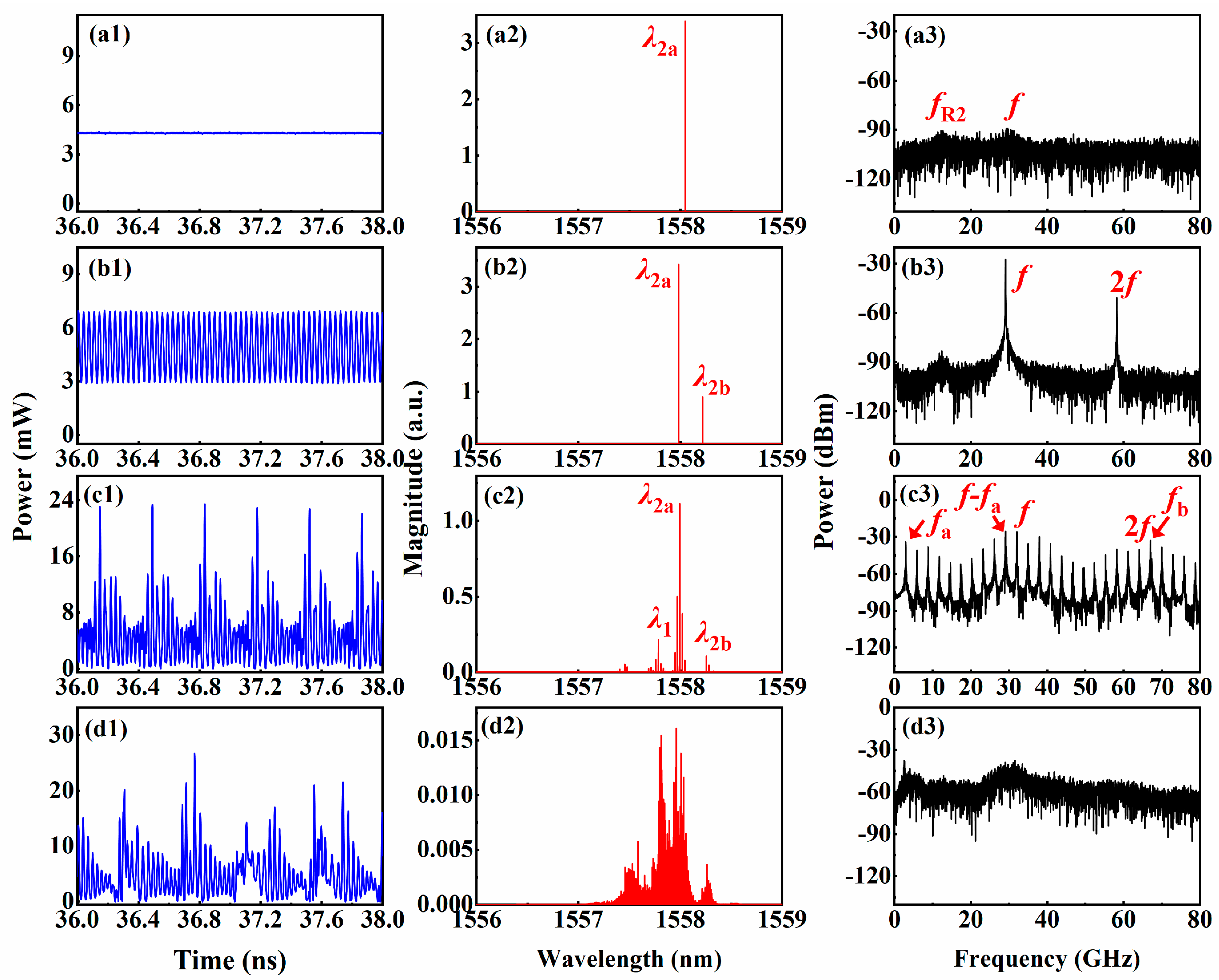
Figure 3.
Diagram of dynamic state of the IFSSL in the parameter space of IP1 and IDFB2, where IDFB1 = 60 mA, IP2 = 0 mA, IA = 0 mA and the different colors denote different states.
Figure 3.
Diagram of dynamic state of the IFSSL in the parameter space of IP1 and IDFB2, where IDFB1 = 60 mA, IP2 = 0 mA, IA = 0 mA and the different colors denote different states.
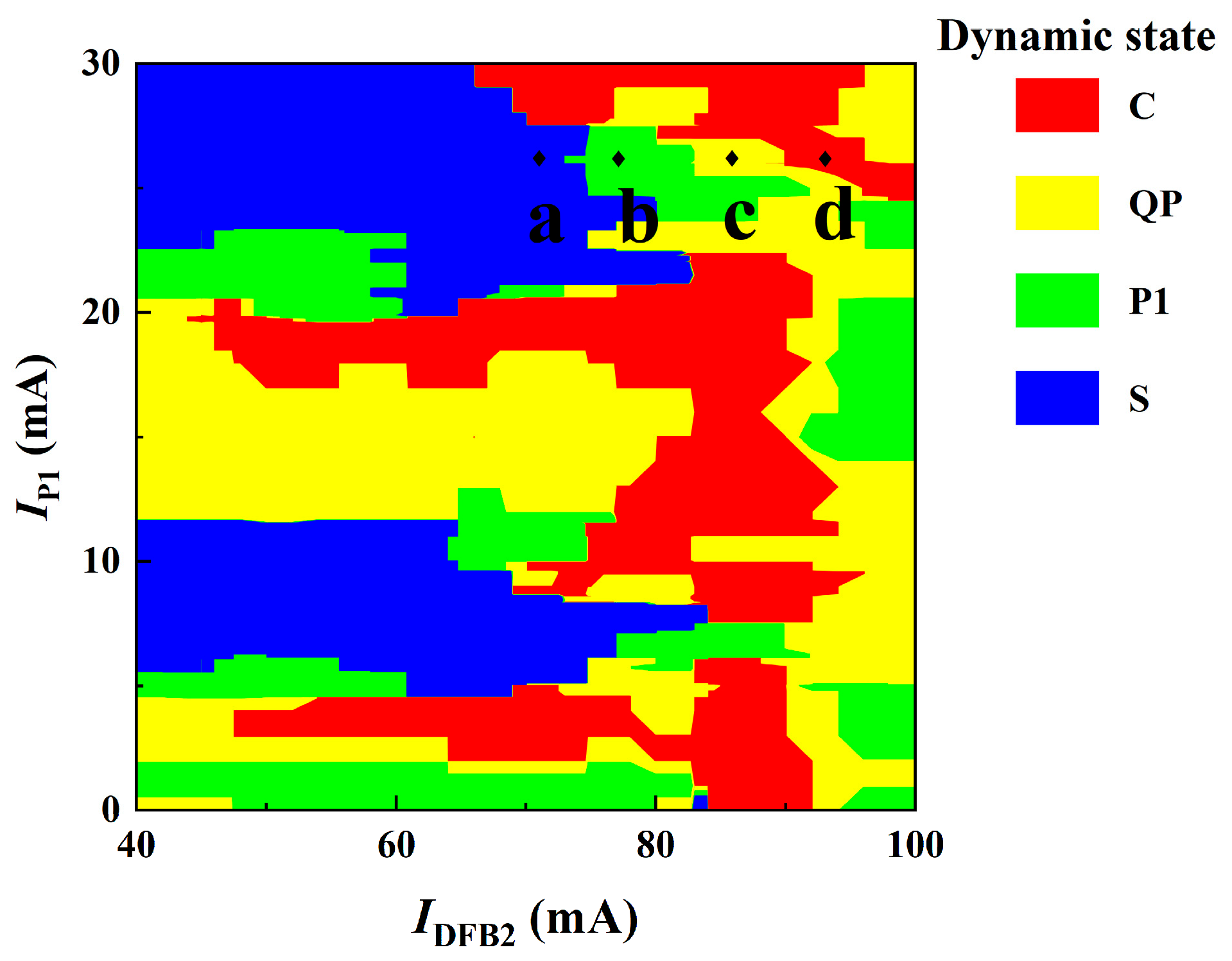
Figure 4.
Diagram of dynamic state of the IFSSL under different IP2 and IA, When IDFB1 = 60 mA, IP1 = 26 mA and IDFB2 are (a) 71 mA, (b) 77 mA, (c) 86 mA and (d) 93 mA. The different colors correspond to different states.
Figure 4.
Diagram of dynamic state of the IFSSL under different IP2 and IA, When IDFB1 = 60 mA, IP1 = 26 mA and IDFB2 are (a) 71 mA, (b) 77 mA, (c) 86 mA and (d) 93 mA. The different colors correspond to different states.

Figure 5.
Chaos synchronization of IFSSLA and IFSSLB. (a) Temporal waveforms of response IFSSLA and IFSSLB; (b) correlation plots of response IFSSLA and IFSSLB; (c) temporal waveforms of driving signal SLD and response IFSSLA; (d) correlation plots of driving signal SLD and response IFSSLA.
Figure 5.
Chaos synchronization of IFSSLA and IFSSLB. (a) Temporal waveforms of response IFSSLA and IFSSLB; (b) correlation plots of response IFSSLA and IFSSLB; (c) temporal waveforms of driving signal SLD and response IFSSLA; (d) correlation plots of driving signal SLD and response IFSSLA.
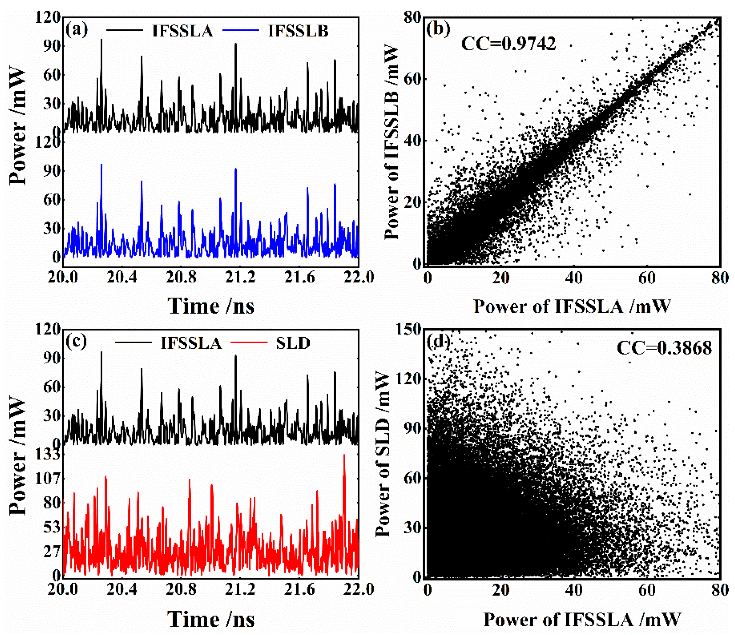
Figure 6.
The effects of the injection power on synchronization quality under different conditions (a) IDFB1, (b) IDFB2 and (c) IA where: IP1 = 26 mA, IP2 = 15 mA, (a) IDFB2 = 77 mA, IA = 15 mA; (b) IDFB1 = 60 mA, IA = 15 mA; (c) IDFB1 = 60 mA, IDFB2 = 77 mA.
Figure 6.
The effects of the injection power on synchronization quality under different conditions (a) IDFB1, (b) IDFB2 and (c) IA where: IP1 = 26 mA, IP2 = 15 mA, (a) IDFB2 = 77 mA, IA = 15 mA; (b) IDFB1 = 60 mA, IA = 15 mA; (c) IDFB1 = 60 mA, IDFB2 = 77 mA.
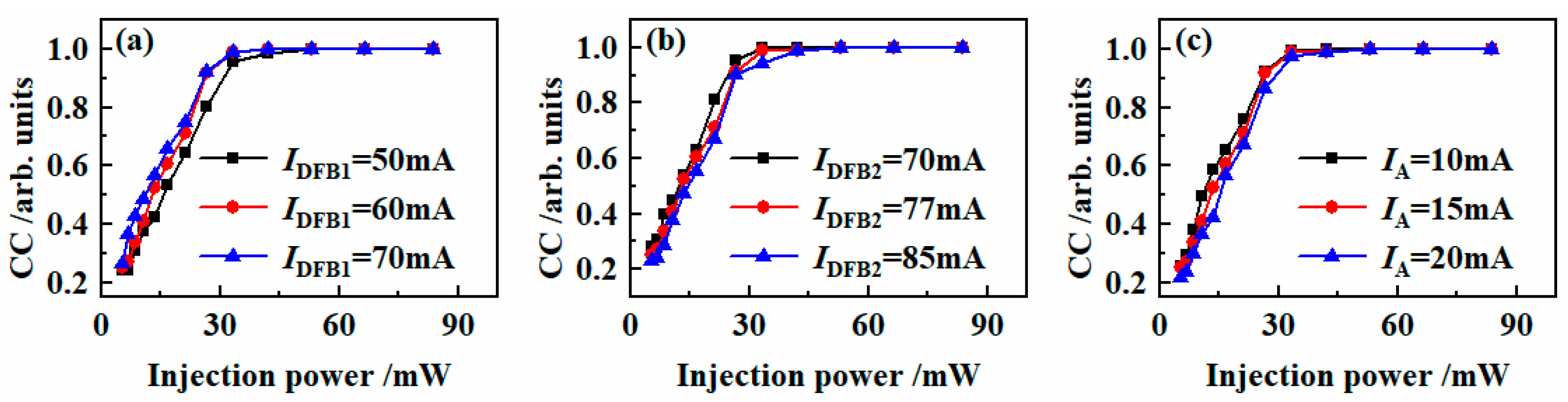
Figure 7.
Effects of the current mismatch of the five sections on the synchronization coefficient of IFSSLA and IFSSLB.
Figure 7.
Effects of the current mismatch of the five sections on the synchronization coefficient of IFSSLA and IFSSLB.

Table 1.
Parameter values of IFSSL used in VPI.
| Parameter | Description | Value |
|---|---|---|
| LDFB1 | DFB1 section length | 200 μm |
| LP1 | P1 section length | 400 μm |
| LDFB2 | DFB2 section length | 200 μm |
| LP2 | P2 section length | 400 μm |
| LA | A section length | 320 μm |
| WA | Active region width | 2.50 μm |
| aI | Internal loss factor | 1000 m−1 |
| α | Linewidth enhancement factor | 4 |
| Ci | Index grating coupling coefficient | 15,500 m−1 |
| Cg | Gain grating coupling coefficient | 2000 m−1 |
| N0 | Transparency carrier density | 1.40 × 1024 m−3 |
| Gnon | Nonlinear gain coefficient | 1.00 × 10⁻²³ m3 |
| Gm | Linear material gain coefficient | 3.00 × 10⁻²⁰ m2 |
| CMQW | Confinement factor MQW | 0.07 |
| Λg | Group index | 3.70 |
Disclaimer/Publisher’s Note: The statements, opinions and data contained in all publications are solely those of the individual author(s) and contributor(s) and not of MDPI and/or the editor(s). MDPI and/or the editor(s) disclaim responsibility for any injury to people or property resulting from any ideas, methods, instructions or products referred to in the content. |
© 2024 by the authors. Licensee MDPI, Basel, Switzerland. This article is an open access article distributed under the terms and conditions of the Creative Commons Attribution (CC BY) license (https://creativecommons.org/licenses/by/4.0/).
Share and Cite
MDPI and ACS Style
Guo, Y.; Du, Y.; Gao, H.; Tan, M.; Zhao, T.; Jia, Z.; Chang, P.; Wang, L. Chaos Synchronization of Integrated Five-Section Semiconductor Lasers. Entropy 2024, 26, 405. https://doi.org/10.3390/e26050405
AMA Style
Guo Y, Du Y, Gao H, Tan M, Zhao T, Jia Z, Chang P, Wang L. Chaos Synchronization of Integrated Five-Section Semiconductor Lasers. Entropy. 2024; 26(5):405. https://doi.org/10.3390/e26050405
Chicago/Turabian StyleGuo, Yuanyuan, Yao Du, Hua Gao, Min Tan, Tong Zhao, Zhiwei Jia, Pengfa Chang, and Longsheng Wang. 2024. "Chaos Synchronization of Integrated Five-Section Semiconductor Lasers" Entropy 26, no. 5: 405. https://doi.org/10.3390/e26050405
Note that from the first issue of 2016, this journal uses article numbers instead of page numbers. See further details here.