Article

Investigation on the Performances of Vuilleumier Cycle Heat Pump Adopting Mixture Refrigerants

Department of Power Engineering, North China Electric Power University, Baoding 071000, China
*
Author to whom correspondence should be addressed.
Entropy 2017, 19(9), 446; https://doi.org/10.3390/e19090446
Submission received: 30 July 2017 / Revised: 22 August 2017 / Accepted: 24 August 2017 / Published: 26 August 2017
(This article belongs to the Section Thermodynamics)

Abstract

:
The performances of thermodynamics cycles are dependent on the properties of refrigerants. The performances of Vuilleumier (VM) cycle heat pump adopting mixture refrigerants are analyzed by MATLAB software using REFPROP programming. At given operating parameters and configuration, performances of the VM cycle adopting pure refrigerant, H2, He or N2 are compared. Thermodynamic properties of the four type mixtures, namely, He-H2, He-N2, H2-N2 and He-H2-N2, are obtained with total 16 mixing ratio, and the coefficient of performance and the exergy efficiency of these four mixture types in VM cycle heat pump are calculated. The results indicate that within the temperature of heat source 400–1000 K, helium is the best choice of pure refrigerant for VM cycle heat pump. The He-H2 mixture is the best among all binary refrigerant mixtures; the recommended proportion is 1:2. For trinary refrigerant mixture, suggested proportion of helium, hydrogen and nitrogen is 2:2:1. For these recommended mixtures, system COPs (coefficient of performances) are close to 3.3 and exergy efficiencies are about 0.2, which are close to pure refrigerant helium.

1. Introduction

Vuilleumier (VM) cycle is a thermally driven reversible Stirling gas cycle [1,2]. Selection of heat sources is of great flexibility [3]; it can be fossil fuels such as natural gas, or renewable energy such as solar energy or even waste heat. The advantages of using VM cycle heat pump are small output, low noise, long life span, high efficiency, etc. [4,5]. It can provide cold or hot production, even with power product. The cyclic efficiency of the ideal VM cycle is the same as that of the Carnot cycle [6].
However, the actual coefficient of performance of the VM cycle is only about 30~40% of the ideal cycle, due to the reciprocating flow of refrigerant in the VM cycle heat pump. The inevitable heat transfer and flow losses caused by the flowing of refrigerant account for more than half of the total losses [7], which has great influence on the performances of the VM cycle heat pump. Undoubtedly, different refrigerants have different characteristics in heat transfer and fluid flow. Therefore, the performances of the system vary under different working conditions with different working fluid [8].
Mixture refrigerants are good examples. Chakravarthy et al. obtained mixing criteria with a number of cycles within 4 K to 300 K, including the Stirling gas cycle [9]. Narasimhan and Venkatarathnam experimentally determined the mixture fraction that had the highest exergy efficiency of single-stage refrigeration [10]. Asadnia and Mehrpooya [11] studied the application of mixture refrigerants, namely, nitrogen, helium and hydrogen in Joule Brayton refrigeration cycle. Results showed that the coefficient of performance using the new mixture refrigerants was 0.1710 and the exergy efficiency was 39.5%, both of them were higher than the existing refrigerant. Lee et al. [12] carried out optimum research of a cryogenic refrigeration cycle adopted nitrogen and argon mixture as refrigerant, from the distribution of temperature and the working pressure of compressor. He got the maximum coefficient of performance and the corresponding Carnot cycle efficiency. Lee et al. [13] researched the feasibility and effectiveness of helium-nitrogen mixture as refrigerant in the refrigeration cycle by Peng-Robinson equation of state.
There are more literatures on the mixture refrigeration cycles. Zhejiang University, which owns the National Key Laboratory [14], used the operation pressure ratio method to optimize the cyclic performance for single-stage compression by adopting binary mixture. They also obtained that constituent and the concentration of mixture, the low side pressure of cycle, and the pressure ratio were factors that had an influence on the coefficient of cycle performance. Literature [15] tested a small capacity pre-cooled mixture cycle system, and established a chromatographic analysis method for mixture concentration optimization.
REFPROP is used in these mixture properties investigations. Yin et al. [16] investigated mixtures of SF6-CO2 as working fluids for geothermal power plants by obtaining the thermophysical properties of the mixtures from National Institute of Standards and Technology (NIST) REFPROP software (Version 8.0). Seneviratne et al. [17] extended critical point literature data for methane and propane mixtures in a beta-version of REDPROP 9.2. Rivas et al. [18] measured a suitable doping agent in two CO2-rich, CO2 + SO2 mixtures with the same SO2 composition from 263.15 to 373.19 K and up to 190.10 MPa, and validated the modeling with the REFPROP 9 software.
For VM cycle heat pump, gas hydrogen, helium or nitrogen are common working fluids, but all applications are single-refrigerant, few on the mixture. To know the performances of mixture, we set the given working condition and determine the configuration of all system parts. Using MATLAB and REFPROP software (Version 9.1) to simulate the variation of properties of pure refrigerant hydrogen, helium and nitrogen, calculate the coefficient of performance and exergy efficiency of the system. Then investigate the properties of four type mixtures, He-H2, He-N2, H2-N2 and He-H2-N2, separately. Finally, compare the system performances of mixture cycles at different mixture ratio with that of the pure refrigerant cycle.

2. Working Principle and Performances Calculation for VM Cycle Heat Pump

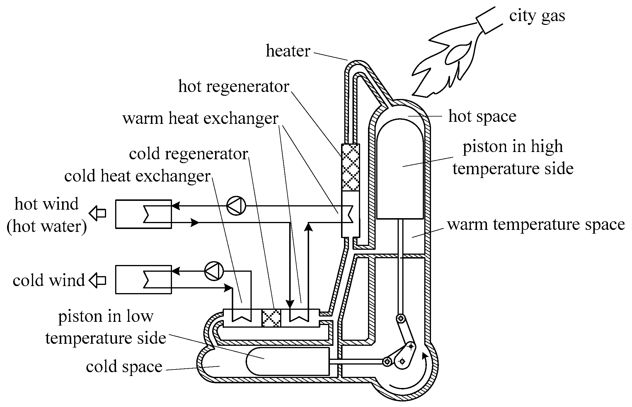
2.1. Working Principle

Figure 1 shows the schematic of VM cycle heat pump. The heat pump mainly contains two cylinders, a cold and a hot cylinder, two passing pistons, two regenerators and three heat exchangers. The two passing pistons are connected to the crankshaft by the driven connecting rod, and the pistons are moved following the rotation of the crankshaft. Between the hot passing piston and the top of hot cylinder is the hot space; while between the cold passing piston and the top of cold cylinder is the cold space. The volume between cold and hot cylinder which varies with the movement of the piston is called warm space.
When the VM cycle heat pump is in heating condition, it absorbs the heat from both heat source and cold source via hot and cold cylinder, then supplies the heat to the user by the warm heat exchanger. While in refrigeration condition, it absorbs the heat of the user, lowers the temperature of the subject, and rejects the heat to the environment at room temperature. Theoretically, in heating or refrigeration mode, the total heat absorbed by the hot space and the cold space is equal to the heat released at the warm space.

2.2. Performances Calculation Method

Formulas used to calculate the performances of VM cycle heat pump are as follows [19,20]:
(1) Travel volume of the cold cylinder:
V c o = 1 4 π D c o 2 Z
(2) Temperature ratio of the hot and cold space:
τ = T h / T c o
(3) Pressure phase angle:
θ = arctan ω ( 1 τ h ) sin φ ( τ c o 1 ) ω ( 1 τ h ) cos φ
(4) Temperature ratio of the cold side:
τ c o = T a / T c o
(5) Temperature ratio of hot side:
τ h = T a / T h
(6) Pressure parameter:
δ = ( τ c o 1 ) 2 + ω 2 ( 1 τ h ) 2 2 ω ( τ c o 1 ) ( 1 τ h ) cos φ ( 1 + τ c o ) + ω ( 1 + τ h )
(7) Pressure ratio:
P max P min = 1 + δ 1 δ
(8) Maximum pressure:
P max = P a v 1 + δ 1 δ
(9) Minimum pressure:
P min = P a v 1 δ 1 + δ
(10) Theoretical cooling capacity of cold cylinder:
Q c o = P a v V c o π n δ sin θ 60 ( 1 + 1 δ 2 )
(11) Theoretical heating absorption of hot cylinder:
Q h = Q c o τ c o 1 1 τ h
(12) Theoretical heating release of warm cylinder:
Q a = Q c o + Q h
(13) Theoretical coefficient of performance of heat pump:
C O P = Q a Q h
(14) Theoretical exergy efficiency of heat pump:
η e = E x , o u t E x , i n E x , h + E x , c o = Q a ( ( 1 T 0 T o u t ) ( 1 T 0 T i n ) ) Q h ( 1 T 0 T h ) + Q c o ( T 0 T c o 1 )

3. Performances of Pure Refrigerants in VM Cycle

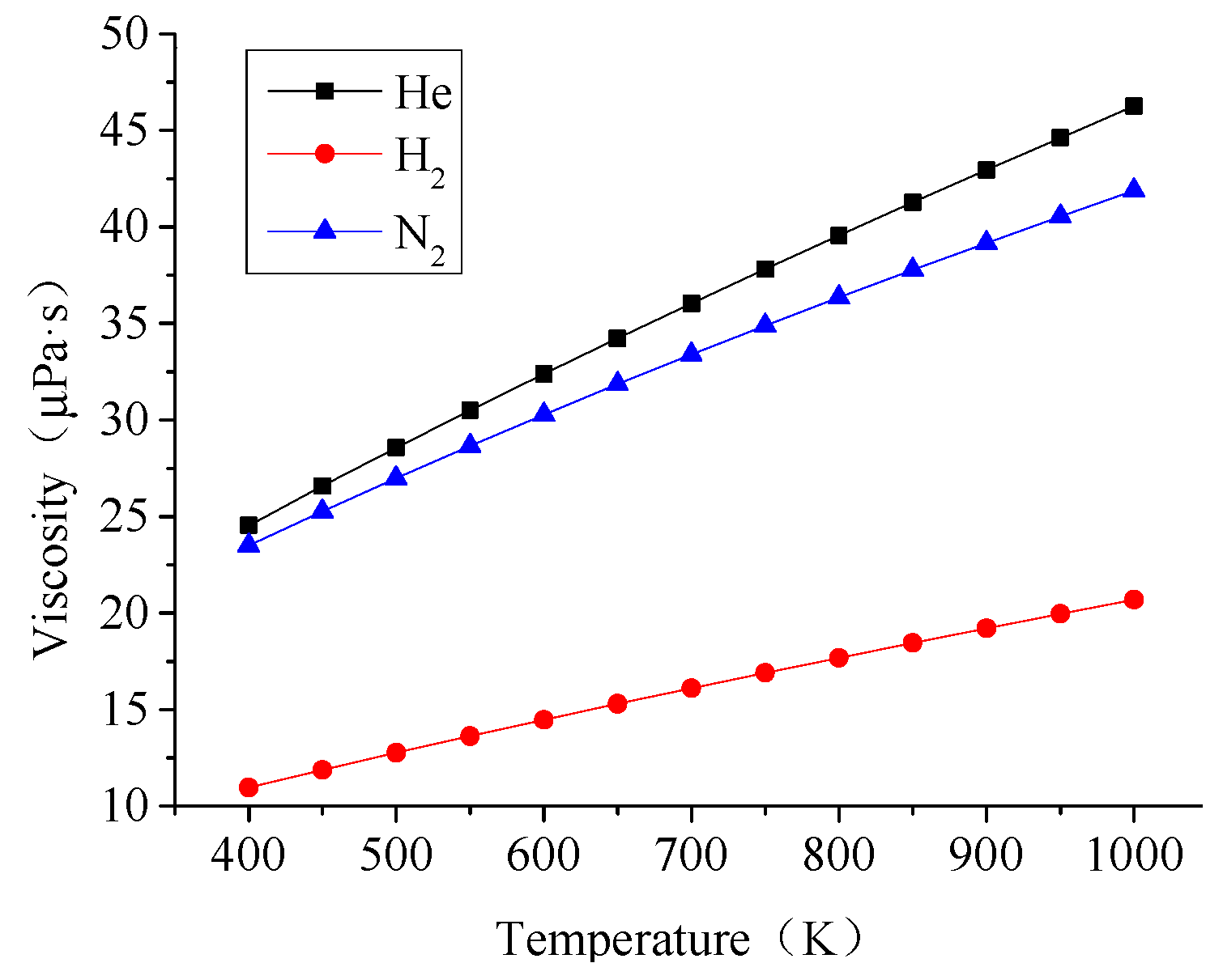
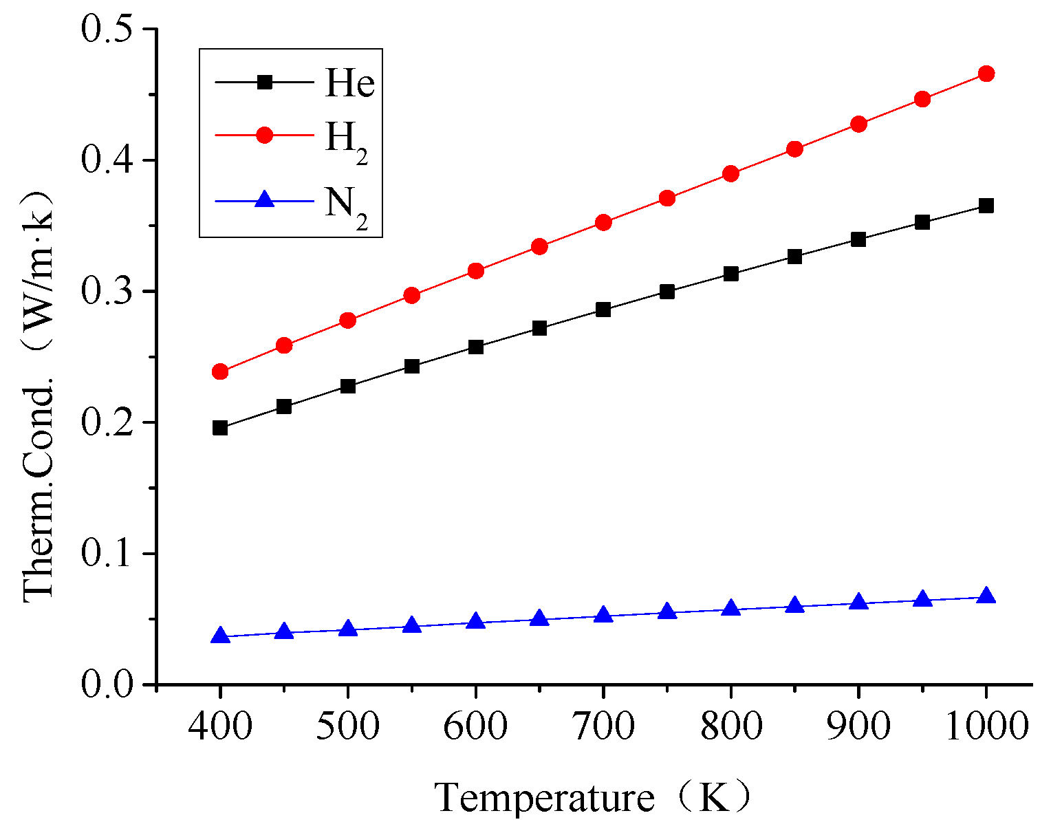
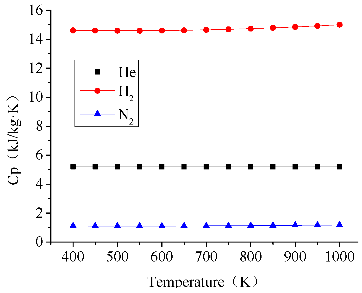
3.1. Properties of Pure Refrigerants

In order to get close to the ideal cycle, the actual VM cycle heat pump should choose the actual gas which is more similar to the ideal gas. Therefore, helium, hydrogen and nitrogen are the most common pure refrigerant to be used in the VM cycle. Here are some of their physical properties:
(1) Helium
Helium is a colorless, odorless gas. Its chemical nature is pretty stable; it could not normally combine with any other element. What is more, helium is the most difficult gas to liquefy in nature owing to the extremely low critical temperature. And the conversion temperature of it is also very low; helium has the lowest boiling point among all gases. In terms of high specific heat capacity, high thermal conductivity and low density, helium is only inferior to hydrogen.
(2) Hydrogen
Generally, hydrogen is also a colorless, odorless gas. It is extremely insoluble in water. It is also a gas with the lightest quality, the largest specific heat, the highest thermal conductivity, and the lowest viscosity of all gases. The conversion temperature of hydrogen is much lower than room temperature, for example, the maximum conversion temperature is only about 204 K. Therefore, in order to produce cold effect, hydrogen must be pre-cooled to 204 K firstly, and then throttled. It is noted that hydrogen belongs to flammable and explosive substances, there is a need for special attention to operate liquid hydrogen, and a need for rigorous control and gauging the purity of liquid hydrogen.
(3) Nitrogen
Similar to helium and hydrogen, nitrogen is also a colorless, odorless gas, it is slightly lighter than air and insoluble in water. The chemical nature of it is also stable, so it is frequently used as a protective gas. Furthermore, because it is non-toxic and has a lower boiling point than air, liquid nitrogen is the safest refrigerant in low-temperature research fields, but should be avoided of asphyxia. Liquid nitrogen is also used as pre-cooling equipment in hydrogen or helium liquefaction installations. To prevent explosions, storage of liquid nitrogen should be careful, avoiding long-time contacting with hydrocarbons.

3.2. Properties Variationof Pure Refrigerants

The physical properties of three refrigerants, helium, hydrogen and nitrogen, are shown from Figure 2, Figure 3 and Figure 4. The temperature range is 400–1000 K.
As illustrated in Figure 2, Figure 3 and Figure 4:
(1) The constant pressure specific heat and thermal conductivity of helium and hydrogen are greater than that of nitrogen, which indicates that helium and hydrogen have advantages over nitrogen in absorbing heat from heat source. However, the loss of heat conduction and heat dissipation is also greater than that of nitrogen.
(2) The viscosity of nitrogen is greater than hydrogen, so nitrogen has larger friction loss, further increasing the pressure loss. It has effect on the pressure ratio, and lower the refrigeration output than hydrogen. However, the viscosity of nitrogen is less than that of the helium.
As a result, each refrigerant has different characteristics in terms of heat transfer and flow resistance. Hydrogen shows the best performance overall. When comparing helium with nitrogen, both of them have advantages in heat transfer and flow, respectively. For example, the flow resistance of nitrogen is smaller, but the heat transfer performance of helium is better.

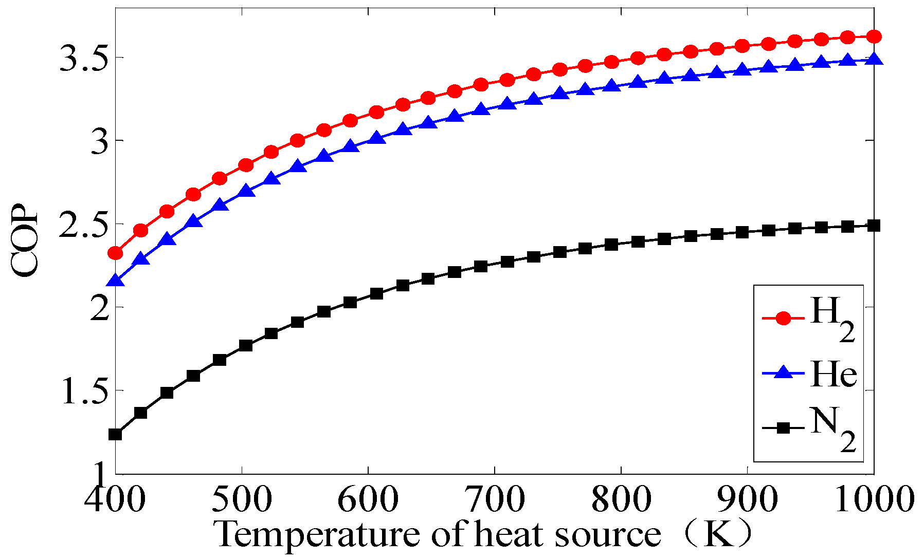
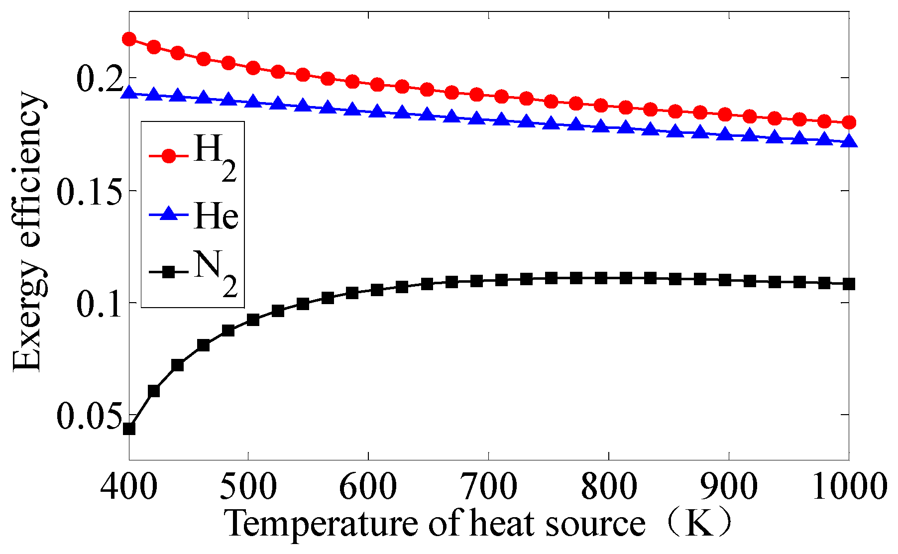
3.3. Performances of Pure Refrigerants

To make a clear comparison, the configuration and some operating parameters of the VM heat pump are given in Table 1 and Table 2.
As shown in Figure 5, the COPs (coefficient of performances) of three working fluids increase with the elevation of the heat source temperature. It trends to go gentle at higher temperature. The COPs of heat pump adopting hydrogen and helium are very close, which are higher than that of the nitrogen.
Figure 6 shows the exergy efficiency to temperature of heat source of these three working fluids. Exergy efficiency of the VM cycle heat pump adopting hydrogen and helium decrease as the temperature of the heat source increases. The trends are opposite to that of the COP. While for nitrogen, the exergy efficiency variation trend is the same as that of the COP. They both increase as the temperature of heat source increases.
Therefore, according to the system performances of the three pure refrigerants, helium and hydrogen are similar to each other, better than that of the nitrogen. Considering the liable explosion problem of hydrogen, helium is the best choice of working fluid for VM cycle heat pump. For economic concern, nitrogen should be introduced to lower the cost of the whole facility.

4. Performances for Mixture Refrigerant in VM Cycle

Giacobbe analyzed the heat transfer properties of helium, hydrogen and other inert gases [22]. Hosseinnejad et al. carried out numerical calculations of transport properties on the mixture of hydrogen and inert gas [23]. For security and economy reasons, four kinds of mixture refrigerants were discussed in this paper, namely, helium and hydrogen, helium and nitrogen, hydrogen and nitrogen, helium, hydrogen and nitrogen.

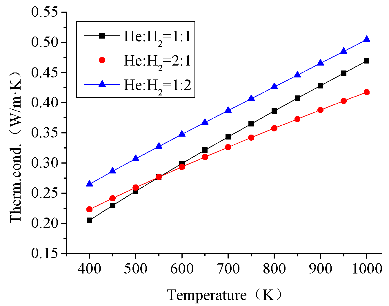
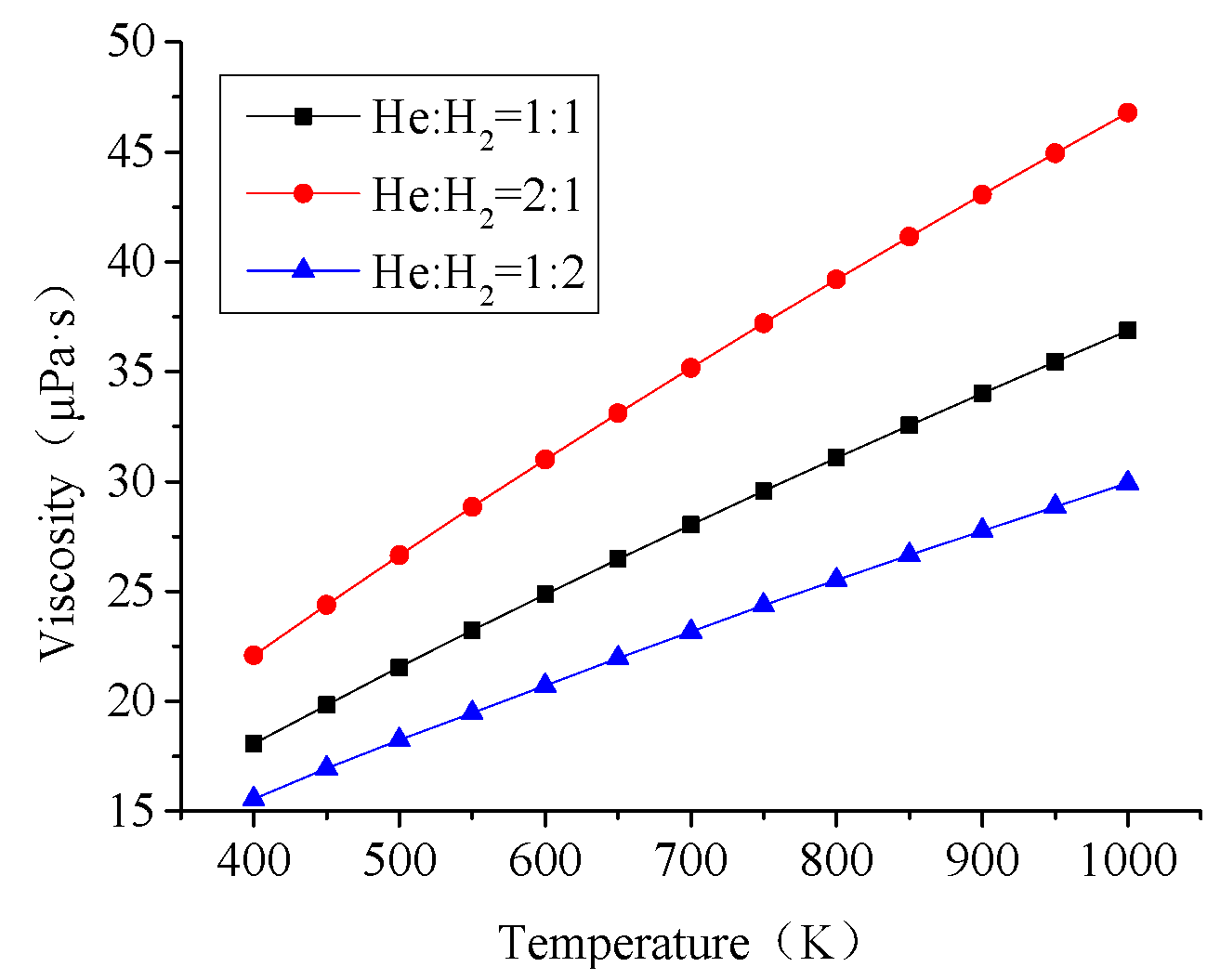
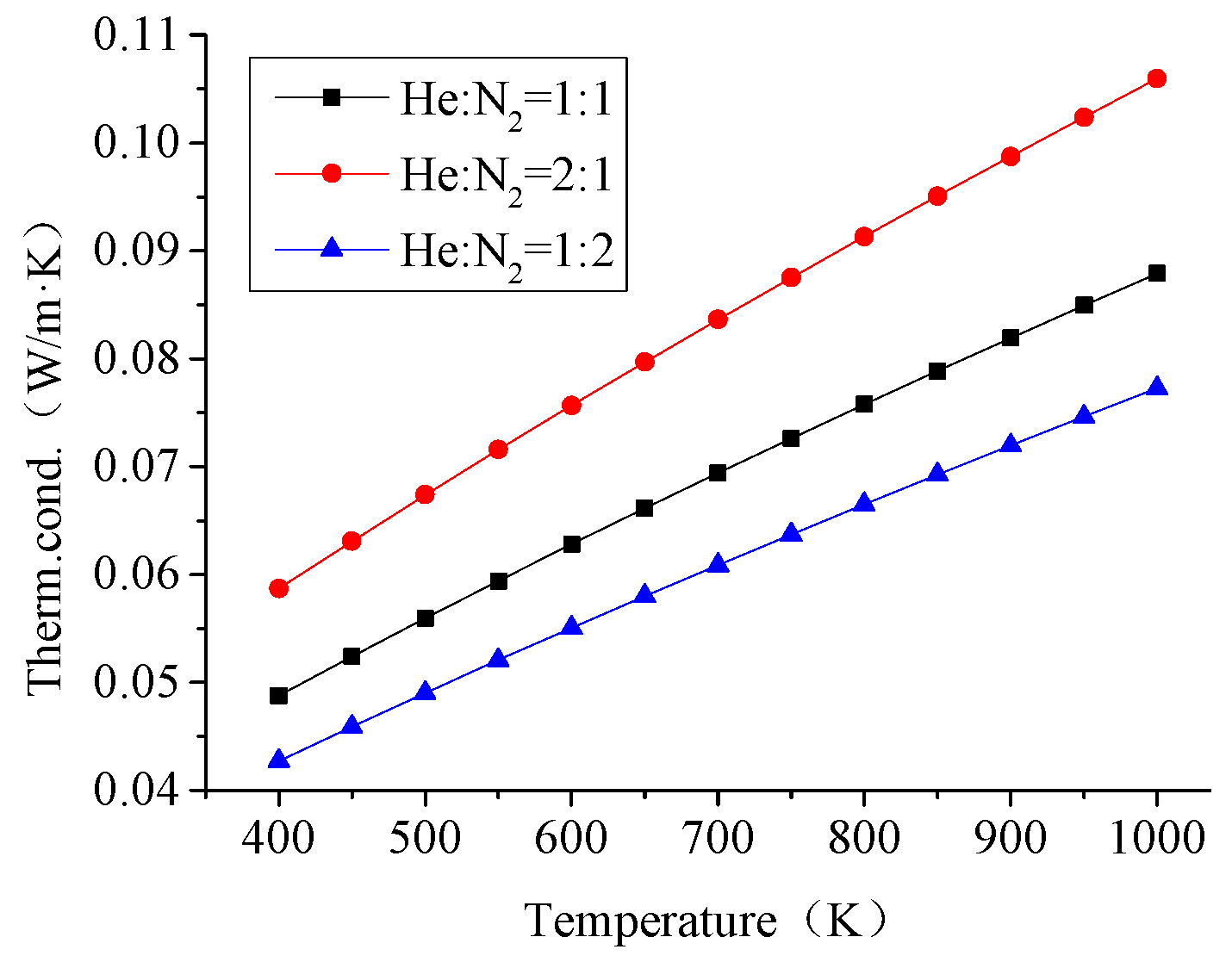
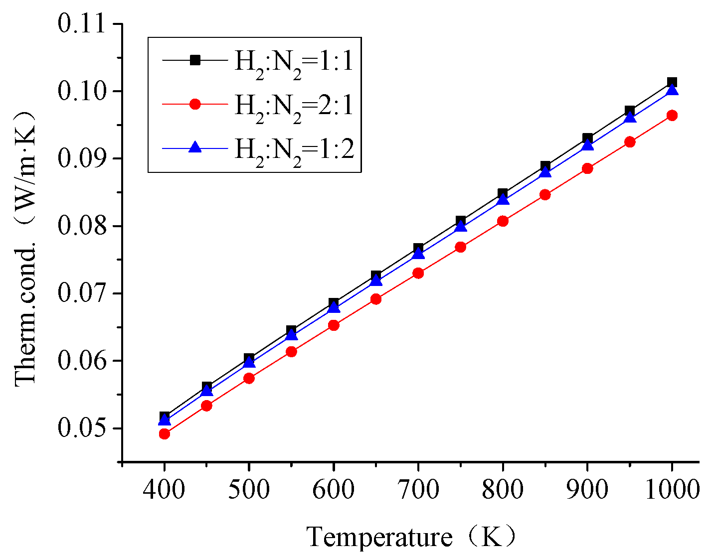
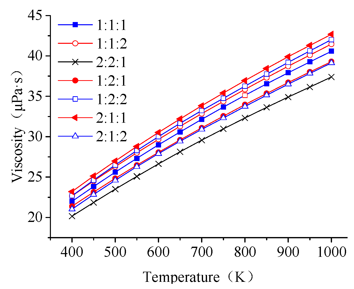
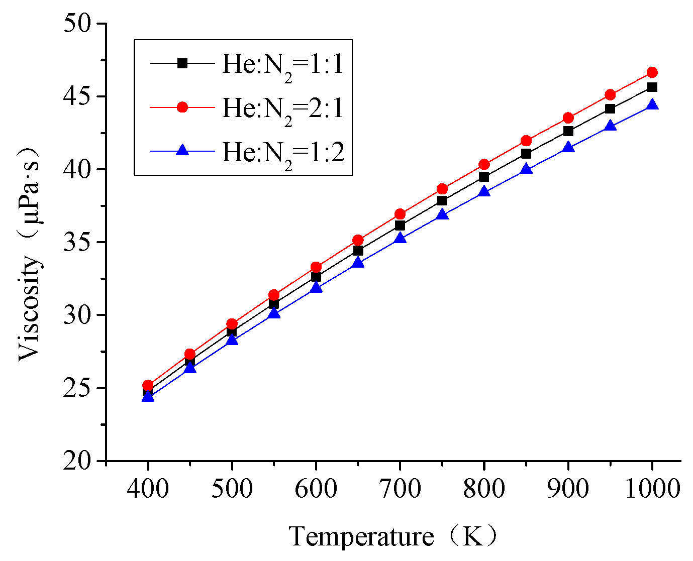
4.1. Properties of Mixture

In Figure 7 and Figure 8, the thermal conductivity and viscosity of helium and hydrogen mixture increase as the elevation of heat source temperature. When at mixing proportion of 1:2, it has the maximum value of the thermal conductivity and the minimum value of viscosity. This could be explained by Figure 2 and Figure 3, in which the thermal conductivity of hydrogen is the highest, but the viscosity is the lowest. Figure 7 also indicates that there are a cross point of mixture proportion 2:1 and 1:1 when the heat source temperature is about 550 K.
Figure 9 and Figure 10 indicate that the thermal conductivity and viscosity of helium and nitrogen mixture also increase with the heat source temperature rise. In addition, the bigger the number of mole fractions of helium, the higher the value of thermal conductivity and viscosity. The curves for viscosity have the same variation, but the difference of viscosity values for the three mixing proportions is relatively small.
Comparing Figure 11 and Figure 12 to Figure 9 and Figure 10, we can find that the change regulations of He-N2 and H2-N2 are similar. The difference is the divergence between each value of each mixing proportion. For the H2-N2 mixture, the difference of the thermal conductivity is smaller.
For the helium, hydrogen and nitrogen mixture, the thermal conductivity and viscosity increase as well as the heat source temperature, as shown in Figure 13 and Figure 14. The change of viscosity is obsoleted. Furthermore, for thermal conductivity, at mixing ratio of 1:2:1, 1:2:2, and 2:1:2, the values are relatively small; at ratio of 2:1:1, it has the smallest value.

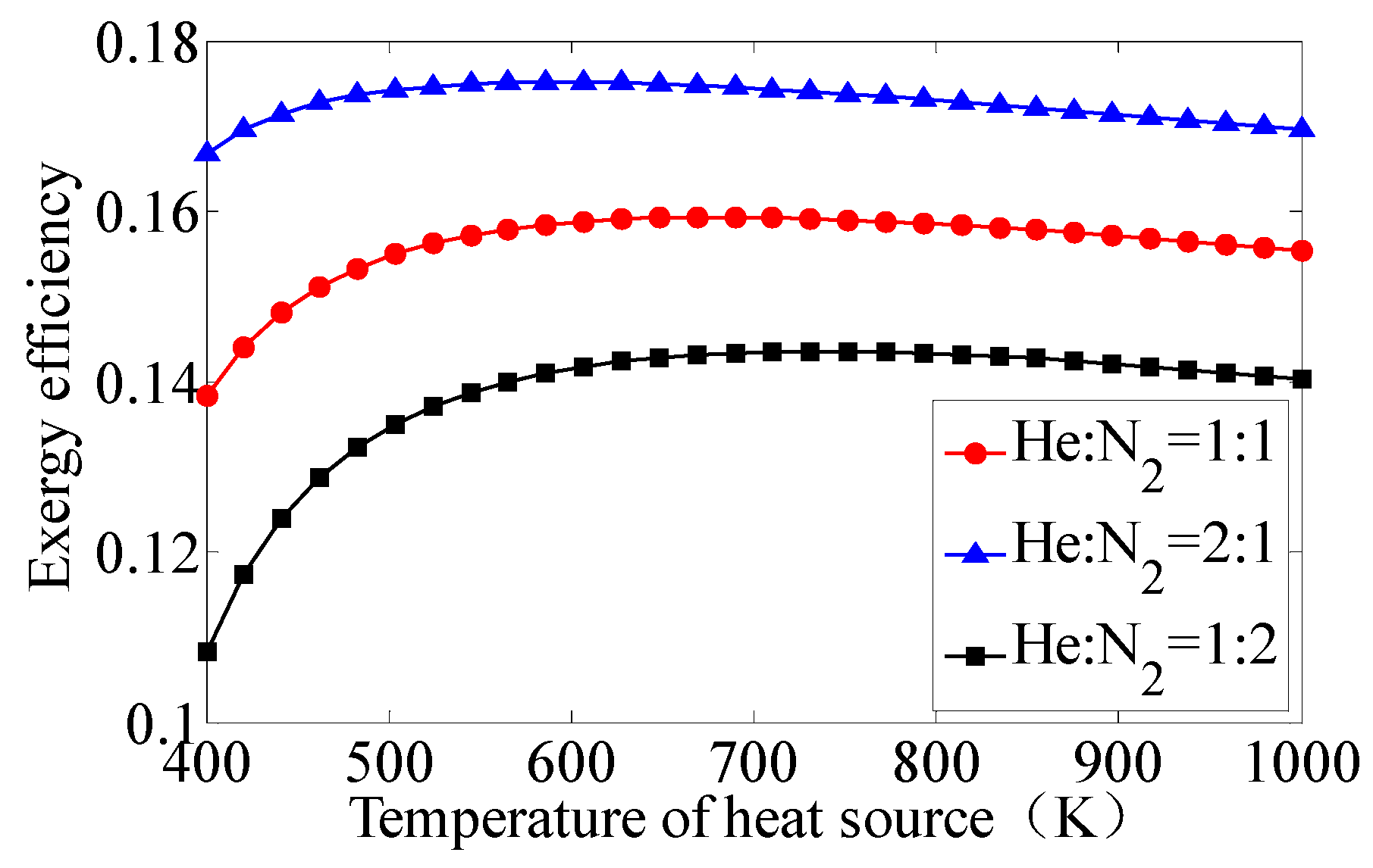
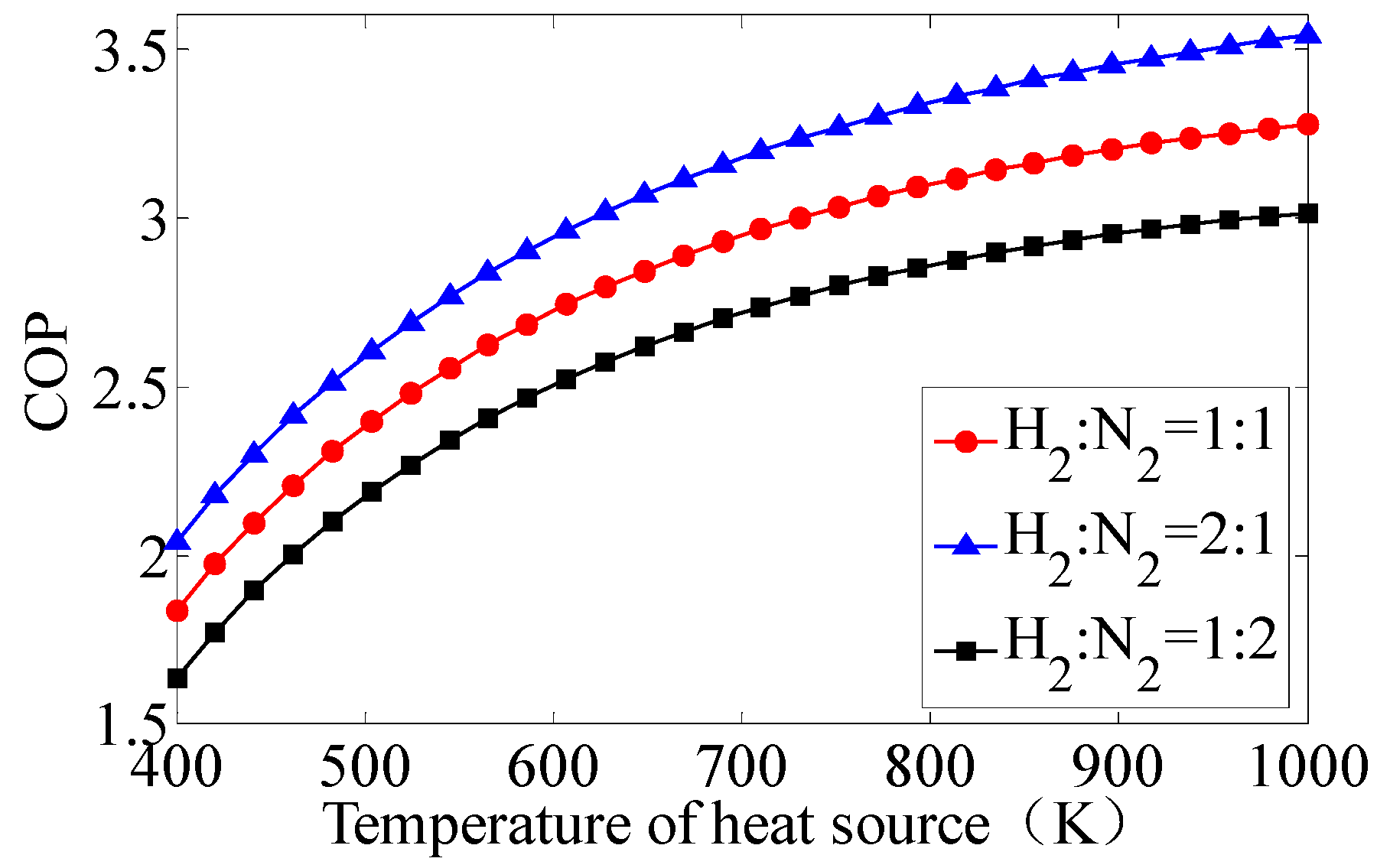
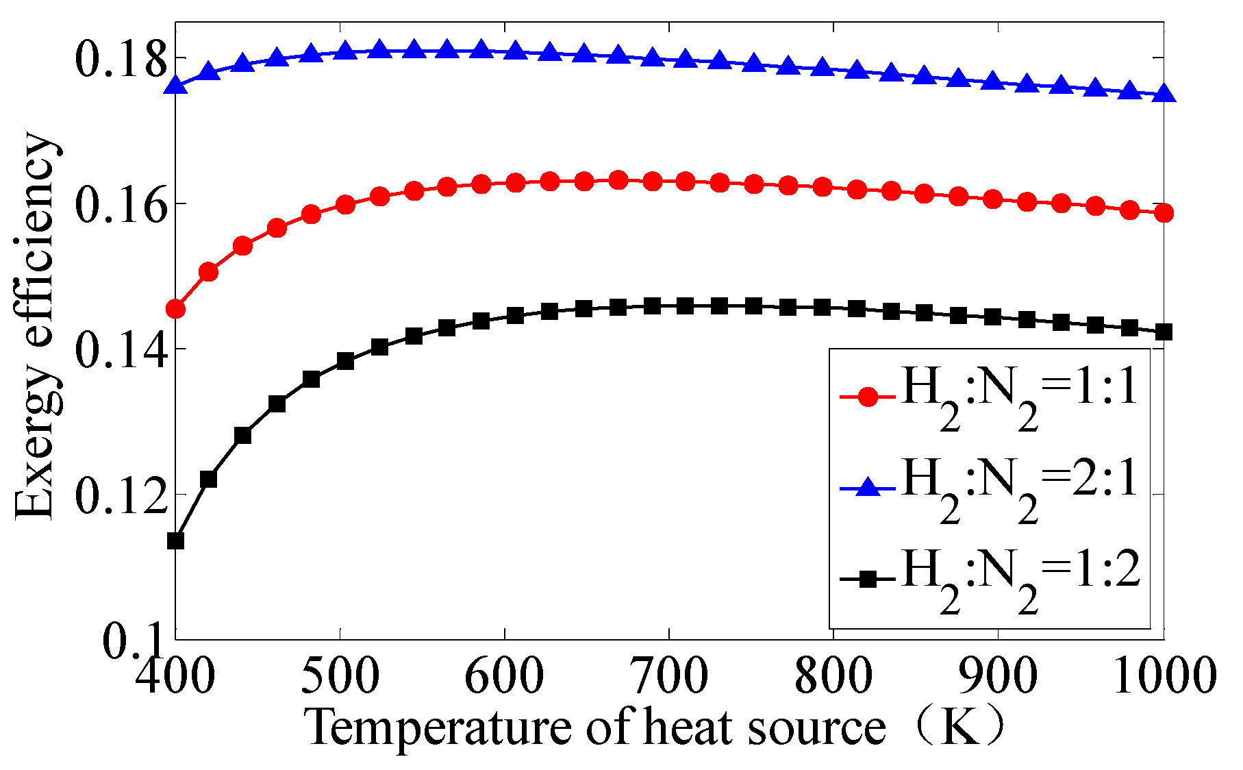
4.2. Result Analysis

Figure 15 and Figure 16 are the COP and exergy efficiency for VM cycle heat pump adopting He-H2 mixture. There is a small difference of COP in different proportions of mixture. The COP increases at elevated temperature, reaches maximum value of 3.5 at calculating range. Mixing ratio of 1:2 has the highest values of exergy efficiency but when temperature approaches 1000 K, the values of exergy efficiency for the three He-H2 mixtures are very close.
Figure 17, Figure 18, Figure 19 and Figure 20 are the COP and exergy efficiency for VM cycle heat pump adopting He-N2 and H2-N2 mixture. The tendency of the two kinds of binary mixtures with different ratio is similar. That is, the higher the heat source temperature, the bigger the value of COP; exergy efficiency goes up then down; the 2:1 proportion of mixture has the largest value of COP and exergy efficiency. Overall, H2-N2 mixture shows better performance than that of the He-N2 mixture.
The COPs of VM cycle heat pump using He-H2-N2 mixture as refrigerant are shown in Figure 21. The COP increases as well as the temperature of heat source. Among the seven mixture ratios, proportion 2:2:1 has the largest COP, it reaches about 3.5 at 1000 K. The difference of COP is relatively small at lower temperature, and becomes bigger at higher temperature.
Figure 22 is the exergy efficiency of VM cycle heat pump adopting the three refrigerant mixtures. At lower temperature, the tendency is not clear. Exergy efficiency for some proportion mixture goes up, while some goes down. There are crossover points between mixing ratio 1:2:1 to 2:1:1 and mixing ratio 1:2:2 to 2:1:2. At higher temperature, the exergy efficiency declines. Mixing ratio 1:1:2 has the worst curve of exergy efficiency.
To sum up, there are 16 mixing ratios and four kinds of mixture refrigerants investigated in this paper. For binary He-H2 mixture, the difference of COP is not significant; ratio 1:2 has higher exergy efficiency. For binary He-N2 or H2-N2, ratio 2:1 has both higher COP and exergy efficiency. Basically, the overall system performances of mixture H2-N2 are better than mixture He-N2. For trinary He-H2-N2 mixture, at the proportion of 2:2:1, the system has the best COP and exergy efficiency.

5. Conclusions

Mixture refrigerants may have effects on the cycle performances. In this paper, at the temperature of heat source within 400–1000 K and at given system configuration parameters, the COP and exergy efficiency of VM cycle heat pump adopting mixture as refrigerants are calculated, and compared with each other or pure refrigerants. We can draw conclusions as follows:
(1)
For pure refrigerants, helium and hydrogen are similar to each other, better than that of nitrogen. Considering the liable explosion problem of hydrogen, helium is the best choice of pure refrigerant for VM cycle heat pump.
(2)
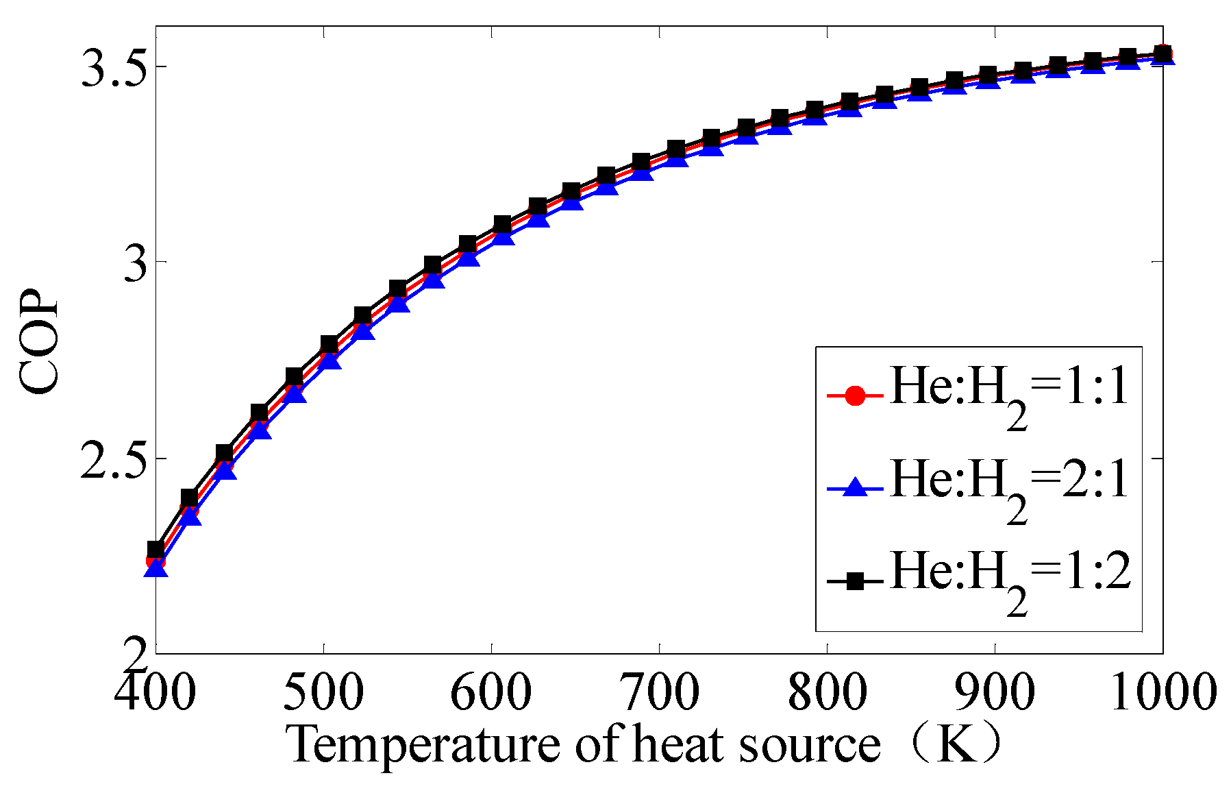
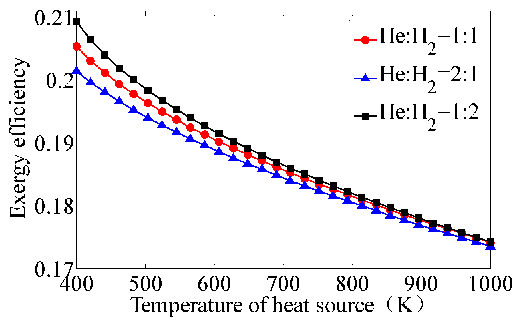
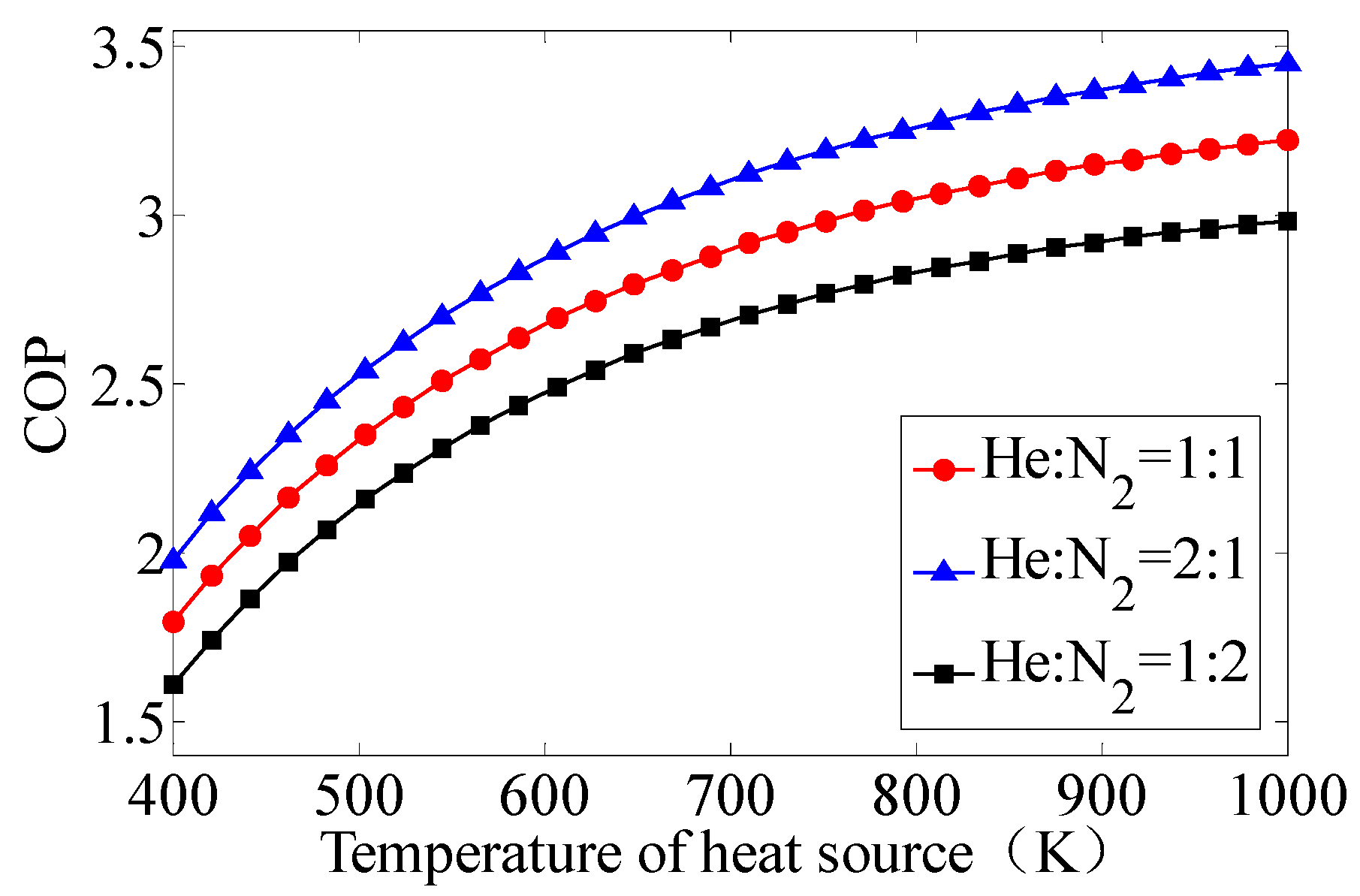
For binary mixture, He-H2 mixture has optimum thermodynamic performance, the recommended ratio is 1:2. The other binary mixture is also an optimum proportion of mixture.
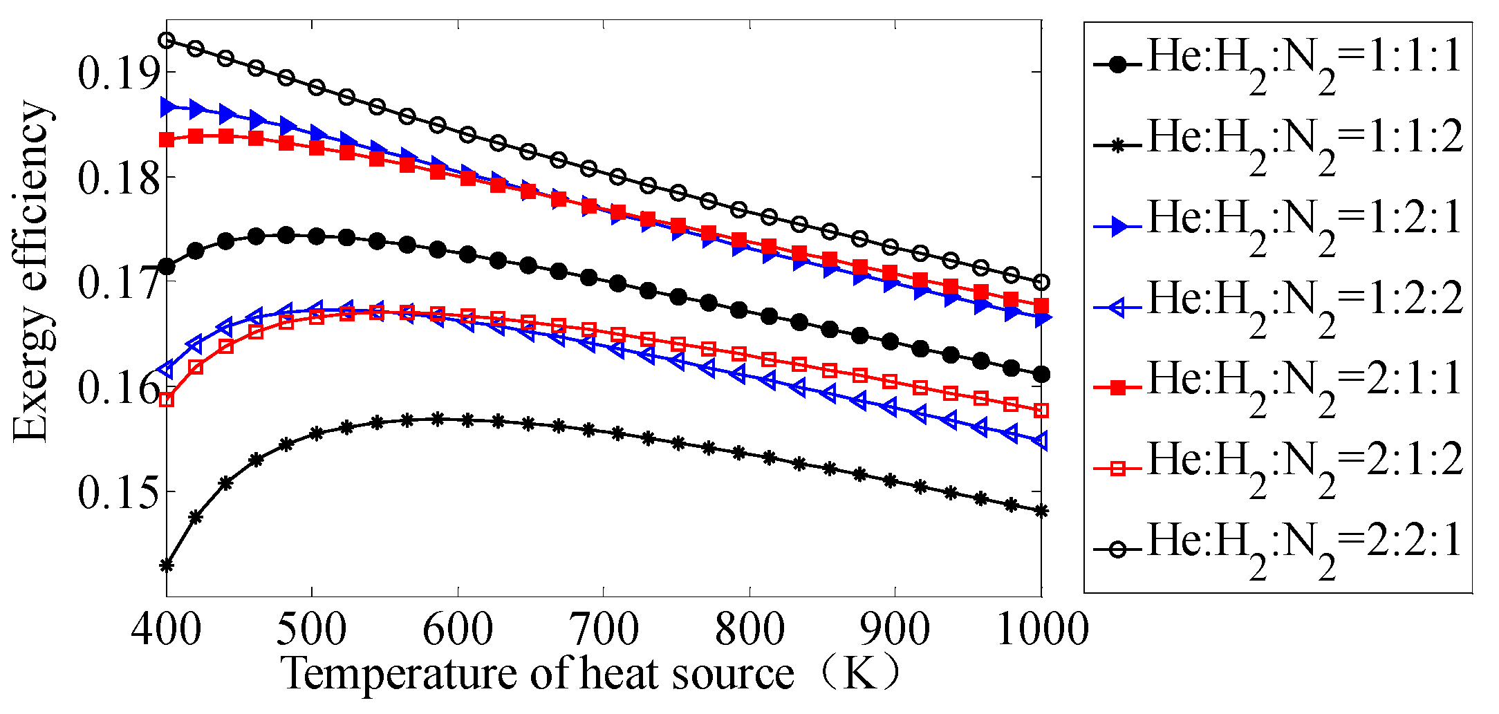
(3)
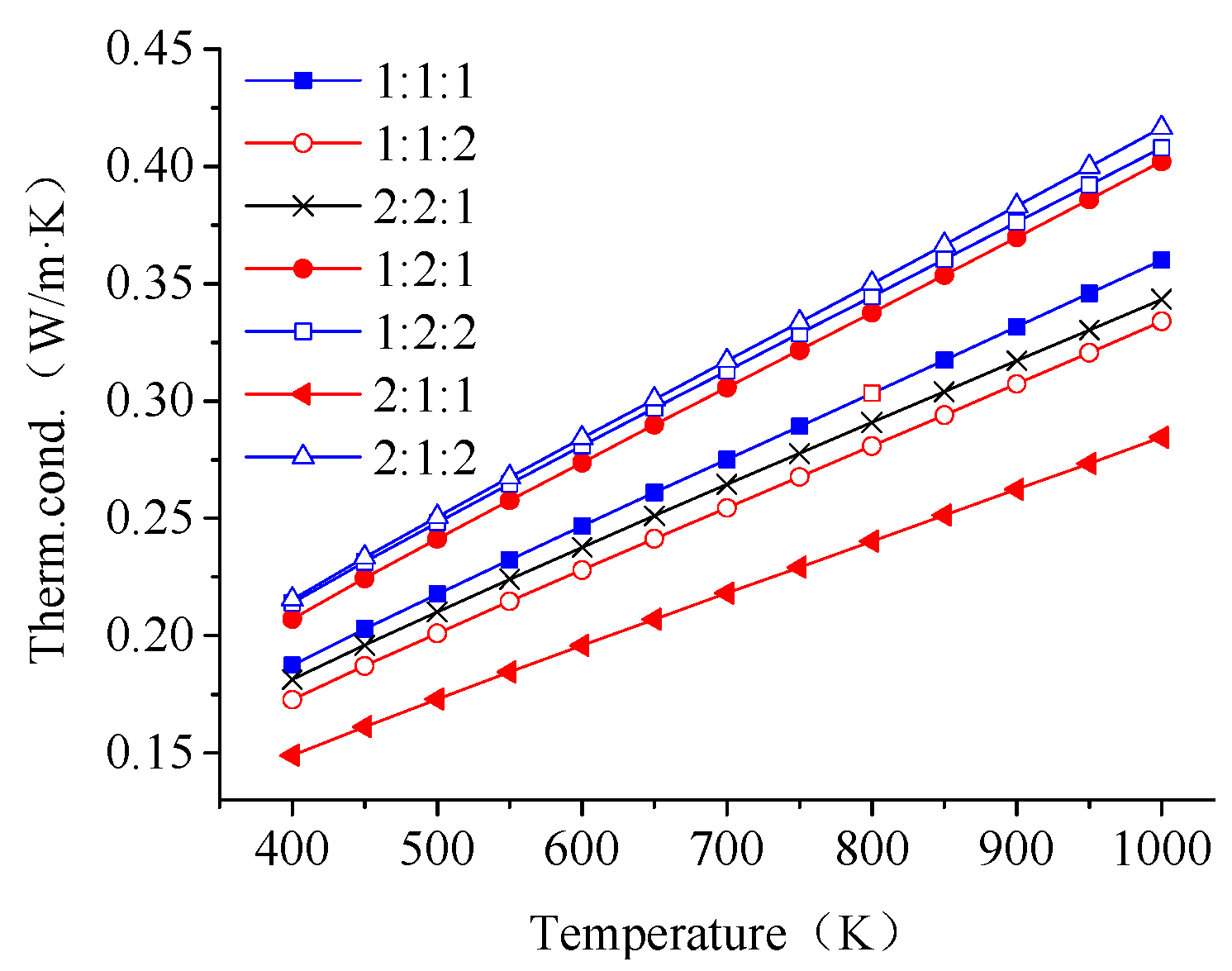
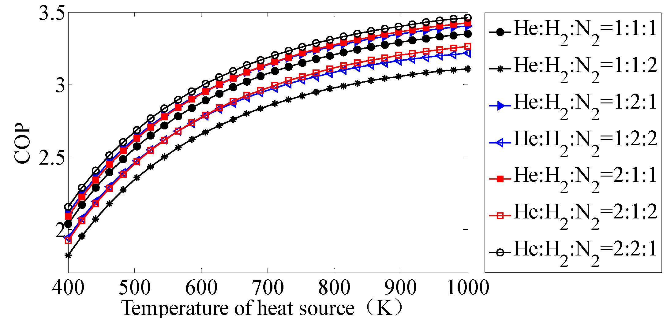
For trinary mixture, at the proportion of He-H2-N2 mixture is 2:2:1, the system has the best COP and exergy efficiency. Furthermore, all the system performances of recommended binary and trinary mixture are close to pure refrigerant helium. For these recommended binary and trinary mixtures, system COPs are close to 3.3 and exergy efficiencies are about 0.2, which are close to pure refrigerant helium.

Acknowledgments

The Project is supported by the Natural Science Foundation of Hebei province. (No. E2014502085).

Author Contributions

Yingbai Xie proposed and designed the research; Kai Zhong performed the calculation. Both authors jointly worked on deriving the results and wrote the paper. Both authors have read and approved the final manuscript.

Conflicts of Interest

The authors declare no conflict of interest.

Nomenclature

SymbolImplication
COPCoefficient of performance
DcoDiameter of cold cylinder
Ex,coExergy of cold space
Ex,hExergy of heat space
Ex,inExergy of fluid inlet
Ex,outExergy of fluid outlet
PavAverage pressure
PmaxMaximum pressure
PminMinimum pressure
QaTheoretical heating release of warm cylinder
QcoTheoretical heat capacity absorbed by cold cylinder
QhTheoretical heating absorption of hot cylinder
TaTemperature of warm space
TcoTemperature of cold space
ThTemperature of hot space
TinInlet temperature
ToAmbient temperature
ToutOutlet temperature
VcoTravel volume of the cold cylinder
ZDistance of the stroke
τTemperature ratio
τcoTemperature ratio of the cold side
τhTemperature ratio of the hot side
φPhase angle of volume
θPressure phase angle
δPressure parameter
nRotation rate
ωProportion of volume
ηeTheoretical exergy efficiency

References

  1. Wu, Y.Z. Refrigeration and Cryogenic Technology Principle; High Education Press: Beijing, China, 2007; pp. 26–33. [Google Scholar]
  2. Hachem, H.; Gheith, R.; Aloui, F.; Nasrallah, S.B. Optimization of an air-filled Beta type Stirling refrigerator. Int. J. Refrig. 2017, 76, 296–312. [Google Scholar] [CrossRef]
  3. Demierre, J.; Favrat, D.; Schiffmann, J.; Wegele, J. Experimental investigation of a Thermally Driven Heat Pump based on a double Organic Rankine Cycle and an oil-free Compressor-Turbine Unit. Int. J. Refrig. 2014, 44, 91–100. [Google Scholar] [CrossRef]
  4. Xie, Y.B.; Sun, G.L.; Zong, L.X. Thermodynamic analysis in natural gas driven VM cycle heat pump. J. Eng. Thermophys. 2010, 31, 373–376. [Google Scholar]
  5. Deng, X.D. Investigation on the Application of VM Cycle Heat Pump in Distributed Energy System. Master’s Thesis, North China Electric Power University, Baoding, China, 2016. [Google Scholar]
  6. Schulz, S.; Thomas, B. Experimental investigation of a free-piston Vuilleumier refrigerator. Int. J. Refrig. 1995, 18, 51–57. [Google Scholar] [CrossRef]
  7. Xie, Y.B.; Sun, X.J. Thermodynamic analysis of a waste heat driven Vuilleumier cycle heat pump. Entropy 2015, 17, 1452–1465. [Google Scholar] [CrossRef]
  8. Pan, C.; Chen, L.; Zhou, Y.; Wang, J. CFD simulation and optimize of a 10K VM refrigerator. Phys. Procedia 2015, 67, 479–484. [Google Scholar] [CrossRef]
  9. Chakravarthy, V.S.; Shah, R.K.; Venkatarathnam, G. A review of refrigeration methods in the temperature range 4–300 K. J. Therm. Sci. Eng. Appli. 2011, 3, 020801. [Google Scholar] [CrossRef]
  10. Narasimhan, N.L.; Venkatarathnam, G. Effect of mixture composition and hardware on the performance of a single stage JT refrigerator. Cryogenics 2011, 51, 446–451. [Google Scholar] [CrossRef]
  11. Asadnia, M.; Mehrpooya, M. A novel hydrogen liquefaction process configuration with combined mixed refrigerant systems. Int. J. Hydrogen Energy 2017, 42, 15564–15585. [Google Scholar] [CrossRef]
  12. Lee, C.; Jin, L.; Park, C.; Jeong, S. Design of non-flammable mixed refrigerant Joule-Thomson refrigerator for precooling stage of high temperature superconducting power cable. Cryogenics 2017, 81, 14–23. [Google Scholar] [CrossRef]
  13. Lee, J.; Oh, H.; Jeong, S. Investigation of neon–nitrogen mixed refrigerant Joule–Thomson cryocooler operating below 70 K with precooling at 100 K. Cryogenics 2014, 61, 55–62. [Google Scholar] [CrossRef]
  14. Wang, Q.; Sun, T.; Cui, K. Optimization of the performance of an auto-cascade refrigerator with a liquid-gas separator using environmentally benign binary refrigerants. J. Eng. Thermophys. 2010, 31, 549–552. [Google Scholar]
  15. Liu, Y.N.; Sun, B.; Yang, G.M. Study on determination method of components in circulating gas liquefaction system of mixed refrigerants. Chem. Eng. Oil Gas 2011, 40, 294–297. [Google Scholar]
  16. Yin, H.; Sabaua, A.S.; Conklin, J.C.; McFarlane, J.; Qualls, A.L. Mixtures of SF6-CO2 as working fluids for geothermal power plants. Appl. Energy 2013, 106, 243–253. [Google Scholar] [CrossRef]
  17. Seneviratne, K.N.; Hughes, T.J.; Johns, M.L.; Marsh, K.N.; May, E.F. Surface tension and critical point measurements of methane + propane mixtures. J. Chem. Thermodyn. 2017, 111, 173–184. [Google Scholar] [CrossRef]
  18. Rivas, C.; Gimeno, B.; Artal, M.; Blanco, S.T.; Fernández, J.; Velasco, I. High-pressure speed of sound in pure CO2 and in CO2 with SO2 as an impurity using methanol as a doping agent. Int. J. Greenh. Gas Control 2016, 2, 731–751. [Google Scholar] [CrossRef]
  19. Bian, S.X. Miniature Cryogenic Refrigerator; China Machine Press: Beijing, China, 1983; pp. 56–64. [Google Scholar]
  20. Sun, X.J. Simulation and Optimization on the Performance of VM Cycle Heat Pump System. Master’s Thesis, North China Electric Power University, Baoding, China, 2015. [Google Scholar]
  21. Xie, Y.B.; Wang, S.H.; Li, B.; Liu, Y. Influences of binary mixtures on the regenerator of VM cycle heat pump. Appl. Mech. Mater. 2011, 52, 249–254. [Google Scholar] [CrossRef]
  22. Giacobbe, F.W. Heat transfer capability of selected binary gaseous mixtures relative to helium and hydrogen. Appl. Therm. Eng. 1998, 18, 199–206. [Google Scholar] [CrossRef]
  23. Hosseinnejad, T.; Behnejad, H.; Shahmir, V.H. Calculation of transport properties and intermolecular potential energy function of the binary mixtures of H2, with Ne, Ar, Kr and Xe by a semi-empirical inversion method. Fluid Phase Equilibria 2007, 258, 155–167. [Google Scholar] [CrossRef]
Figure 1. Schematic of Vuilleumier (VM) cycle heat pump.
Entropy 19 00446 g001
Figure 2. The thermal conductivity of three refrigerants.
Entropy 19 00446 g002
Figure 3. The viscosity of three refrigerants.
Entropy 19 00446 g003
Figure 4. The constant pressure specific heat of three refrigerants.
Entropy 19 00446 g004
Figure 5. The COP (coefficient of performance) for the three pure refrigerants.
Entropy 19 00446 g005
Figure 6. The exergy efficiency of three refrigerants.
Entropy 19 00446 g006
Figure 7. Thermal conductivity for He-H2 mixture.
Entropy 19 00446 g007
Figure 8. Viscosity for He-H2 mixture.
Entropy 19 00446 g008
Figure 9. Thermal conductivity for He-N2 mixture.
Entropy 19 00446 g009
Figure 10. Viscosity for He-N2 mixture.
Entropy 19 00446 g010
Figure 11. Thermal conductivity for H2-N2 mixture.
Entropy 19 00446 g011
Figure 12. Viscosity for H2-N2 mixture.
Entropy 19 00446 g012
Figure 13. Thermal conductivity for He-H2-N2 mixture.
Entropy 19 00446 g013
Figure 14. Viscosity for He-H2-N2 mixture.
Entropy 19 00446 g014
Figure 15. The COP for He-H2 mixture.
Entropy 19 00446 g015
Figure 16. The exergy efficiency for He-H2 mixture.
Entropy 19 00446 g016
Figure 17. The COP for He-N2 mixture.
Entropy 19 00446 g017
Figure 18. The exergy efficiency for He-N2 mixture.
Entropy 19 00446 g018
Figure 19. The COP for H2-N2 mixture.
Entropy 19 00446 g019
Figure 20. The exergy efficiency for H2-N2 mixture.
Entropy 19 00446 g020
Figure 21. The COP for He-H2-N2 mixture.
Entropy 19 00446 g021
Figure 22. The exergy efficiency for He-H2-N2 mixture
Entropy 19 00446 g022
Table 1. Structure parameters of VM cycle heat pump [19,20,21].
ParameterSymbol, Formula, Basis, IntroductionValue
Cylinder boreDco0.0699 m
Distance of runZ0.0312 m
Phase angle of volumeφ90°
The length of passing pistonL0.04359 m
Radial clearance of passing pistonσ0.00015 m
Diameter of regeneratorDR0.0226 m
Length of regeneratorLR0.0226 m
Filler of regeneratorMesh of stainless steel
Pressure parameterδ0.3
Mode of drivingPiston driving of single handle, dual power
Proportion of volumeω10
Rotation raten600 rpm = 10 Hz
Table 2. Calculation parameters of VM cycle heat pump.
ParameterSymbol, Formula, Basis, IntroductionValue
Temperature of hot spaceTh500 K
Temperature of warm spaceTa340 K
Temperature of cold spaceTco300 K
Ambient temperatureT0273 K
Average temperature T a v = T h + T c o 2 400 K
Average pressurePav10.0 × 106 Pa
Theoretical exergy efficiencyηe
Theoretical coefficient of performanceCOP

