
Thermal Analysis of Shell-and-Tube Thermoacoustic Heat Exchangers


Department of Aerospace Engineering, Sharif University of Technology, Tehran 11365-8639, Iran
*
Author to whom correspondence should be addressed.
Entropy 2016, 18(8), 301; https://doi.org/10.3390/e18080301
Submission received: 7 June 2016
/
Revised: 2 August 2016
/
Accepted: 8 August 2016
/
Published: 16 August 2016
(This article belongs to the Section Thermodynamics)
Abstract
:Heat exchangers are of key importance in overall performance and commercialization of thermoacoustic devices. The main goal in designing efficient thermoacoustic heat exchangers (TAHXs) is the achievement of the required heat transfer rate in conjunction with low acoustic energy dissipation. A numerical investigation is performed to examine the effects of geometry on both the viscous and thermal-relaxation losses of shell-and-tube TAHXs. Further, the impact of the drive ratio as well as the temperature difference between the oscillating gas and the TAHX tube wall on acoustic energy dissipation are explored. While viscous losses decrease with , thermal-relaxation losses increase; however, thermal relaxation effects mainly determine the acoustic power dissipated in TAHXs. The results indicate the existence of an optimal configuration for which the acoustic energy dissipation minimizes depending on both the TAHX metal temperature and the drive ratio.
1. Introduction
Today, thermoacoustic engines, coolers, and heat pumps are receiving more industrial interest. While thermoacoustic engines utilize heat to generate acoustic power, the thermoacoustic refrigerators consume the acoustic power to transfer heat from the cold reservoir. In general, there are two basic types of thermoacoustic systems: standing-wave [1] and travelling-wave [2] systems. Thermoacoustic systems have three distinct advantages: first, they have no moving parts and are simple in structure, have low manufacturing costs, and are highly reliable. Further, they are environmentally friendly due to the usage of inert gases as the working fluid. Additionally, heat-driven thermoacoustic devices can be driven by low quality energy sources such as waste heat and solar energy.
The main components of a thermoacoustic device are the stack/regenerators and the two heat exchangers (HXs) that are placed at both ends of the stack/regenerators in an acoustic network. Although steady flow heat exchangers are a mature technology, their design is of key importance in commercialization of thermoacoustic devices where the flow is oscillatory.
All engines and refrigerators must reject waste heat to the ambient temperature where the ambient heat sink is often available as a flowing water stream. Similarly, engines must also accept heat from a heat source at a higher temperature (i.e., burner, waste heat, solar energy, etc.).
The efficiency of thermoacoustic engines is defined as the ratio of produced acoustic power to the heat received by the system [3]. However, irreversible dissipation of acoustic power in different components of thermoacoustic engines due to the viscous and thermal relaxation losses is the main source for performance degradation. Two highly dissipative components of thermoacoustic engines are the regenerators/stacks and the heat exchangers. These components have recently been the subject of many studies for system performance optimization. Wu et al. [4] presented a generalized heat transfer model using a complex heat transfer exponent to optimize the performance of a thermoacoustic engine. Zhibin and Jaworski [5] studied the role of configuration and geometrical dimensions of a regenerator on the acoustic power dissipation. The irreversibility of the porous thermoacoustic stacks in terms of entropy generation is analyzed by Tasnim et al. [6] Chaitou and Nika [7] considered the dependence of acoustic energy on parameters such as stack’s hydraulic radius and stack position.
As pointed out, an optimum design of TAHXs is a critical and challenging task for commercialization of thermoacoustic devices. The relationship between the acoustic energy dissipation, the heat exchanger geometry as well as the operating conditions is of significant importance. In general, while different parallel plate, finned-tube, and shell-and-tube HXs configurations are commonly used, the present knowledge of acoustic energy dissipation in TAHXs is relatively limited. It should be emphasized that designing efficient TAHXs in terms of the required heat transfer rate, in addition to low acoustic energy dissipation, remains a challenge.
Ishikawa and Hobson [8] derived an analytical expression of the time averaged entropy generation in parallel plate HXs. Piccolo [9,10] developed a computational model for studying the entropy generation characteristics of TAHXs with plane fins of a standing-wave thermoacoustic device. Previous studies focused mostly on parallel plate and finned-tube HXs.
It should be pointed out that, in case of high-capacity refrigerators and engines, the thermal conductivity of solids is insufficient to carry the required heats without significant temperature differences; hence, advanced and likely complex heat exchangers have to be used to interweave the process fluid and the working gas, bringing them into intimate thermal contact. A shell-and-tube heat exchanger system is the classical approach [11].
The present paper is focused on the shell-and-tube heat exchanger design of thermoacoustic systems and will investigate the relationship between the acoustic energy dissipation, viscous loss, thermal relaxation loss, and heat exchanger geometry. Much of the motivation behind the current work is driven by the interest as to whether there is a theoretical “optimum” of these parameters and/or the optimum of their combination for a specific operating point. Second, and more generally, the current research attempts to develop a simple but constructive methodology for comparison and evaluation of related heat exchangers at different operating conditions.
In this work, the heat exchangers are considered in the travelling-wave mode with ideal gases based on linear thermoacoustic theory. In this regard, heat exchangers with different geometries are investigated numerically and compared to each other. The dependence of the acoustic power dissipation on heat exchanger metal temperature and drive ratio for a fixed value of heat transfer rate is examined.
2. Theoretical Analysis
2.1. Thermal Modeling of Heat Exchangers
For heat transfer analysis, a local heat transfer coefficient is defined as the ratio of the heat transfer per unit area to the temperature difference between the surface and “bulk” fluid adjacent to the surface. However, in practice, a global heat transfer coefficient derived from a lumped analysis of the heat exchanger (UA-LMTD or effectiveness-NTU methods) is utilized [12].
The surface area, , of the heat exchanger is expressed as
where is the heat transfer rate, denotes the log-mean temperature and is the overall heat transfer coefficient (W·m−2·K−1).
In the above equation, log-mean temperature difference model is used for thermal modeling of the shell-and-tube heat exchanger operating in the unsteady flow. The log-mean temperature difference for thermoacoustic shell-and-tube heat exchangers is formulated as follows:
where is the gas mean temperature, and are the water inlet and outlet temperature, respectively.
In general, a shell-and-tube heat exchanger is considered with gas flowing through the tubes and water flowing over the tubes. The heat transfer in the heat exchanger involves the thermal resistance consisting of three parts: the resistance for heat transfer from the gas to the tube wall, the thermal resistance of the tube, and the resistance for heat transfer from the tube to the water. Therefore, the overall heat transfer coefficient is estimated based on the tube inner diameter according to
where and are the outside and inside tube diameters; and are the tube and shell-side heat transfer coefficient, respectively. Further, is the thermal conductivity of the tube. The shell-side heat transfer coefficient for water, , may be recalled from classical heat exchanger textbooks, such as [12].
It should be pointed out that, for most thermoacoustic-related investigations, the heat transfer from the oscillatory gas to the heat exchanger inner surface area is mainly considered. In other words, the heat transfer across the tube wall and then further to the water is usually embedded. Thus, Equation (1) might be rewritten for heat transfer from the oscillatory gas to the tube wall as follows
where is the temperature of the tube wall at the gas side. This temperature is noted as the HX metal temperature in DeltaEC [13] and also as solid temperature in some TA studies [8,10]. Focusing on the heat transfer in oscillatory gas and employing instead of aids to eliminate the shell side parameters like the tube thickness, tube length and tube pitch which have a negligible influence on the acoustic energy dissipation.
The surface area, , of a shell-and-tube heat exchanger is given as
where is the number of tubes and is the length of the tubes. is calculated according to heat transfer Equation (4).
Thermoacoustic Considerations
It is important to recognize that the problem of heat transfer from an acoustically oscillating gas medium to a solid surface is fundamentally different from that addressed in most discussions of compact heat exchangers that are based on steady unidirectional flow of fluid through the tubes of the heat exchanger. Indeed, TAHXs are distinguished by an oscillatory flow with zero mean velocity and this circumstance has two important implications [14].
The most significant difference between classical HXs and TAHXs is the acoustically oscillating gas parcels which only move a limited distance before reversing their direction of flow. The consequence of their periodic flow reversal is that one cannot arbitrarily increase the length of the heat exchange surfaces (tubes) in the direction of the flow to increase the effective surface area available for heat transfer. Thus, the optimum length, , of the heat exchanger should be of the order of the peak-to-peak displacement of the working gas acoustic displacement amplitude.
Another important aspect of TAHXs is that conventional steady flow heat transfer correlations cannot be directly applied for the estimation of the convective heat transfer coefficient, , between the gas and the solid wall of TAHXs. Different approaches are currently proposed to overcome this limitation.
Swift [3,15] and Garrett [14] suggest an approximate estimation of heat transfer coefficient on the basis of a simple “boundary layer conduction heat transfer” model given as
and
for shell-and-tube heat exchangers. The thermal conductivity of the gas is denoted by and is the thermal penetration depth—that is, the distance through which heat will diffuse in an acoustic cycle.
Mozurkewich [16], Peak et al. [17], Nsofar et al. [18] and Kamsanam et al. [19] also developed different numerical and experimental models of for mostly parallel plate and finned-tube TAHXs. However, for shell-and-tube TAHXs, correlations of heat transfer coefficient are still limited. In this regard, Swift’s model [15] appears to be a sound approximation of for oscillatory flow in shell-and-tube HXs especially when the flow in the tubes is laminar.
The tube side acoustic Reynolds number can be evaluated as follows
where is the hydraulic diameter of the tube.
2.2. Acoustic Energy in TAHXs
According to the linear thermoacoustic theory [1,3], wave propagation in TAHXs is calculated using
where and are oscillating volume velocity and pressure, respectively. is the cross-sectional area of gas channels in the heat exchanger. and are spatially averaged thermoviscous functions and are given in [1,3] in detail. It should be pointed out that, in this paper, thermoviscous functions for cylindrical geometry is considered for shell-and-tube TAHXs. , , and are the ratio of specific heat capacities, sound speed, correction factor for finite solid heat capacity, and mean density of the working gas, respectively.
Furthermore, is expressed as
The time averaged acoustic power produced in a length of the channel is given in complex notation in the general form as
Here, the tilde, “~”, indicates a complex conjugation. Subscript 2 indicates the second order quantity and Re denotes the real part of the complex number.
Substituting Equations (10) and (11) into Equation (13), one obtain as [3]:
In the above equation, the viscous resistance per unit length of the channel, , the thermal relaxation conductance per unit length of the channel, , and the complex gain/attenuation constant for the volume flow rate, , are defined as follows:
and
Here, , and are the Prandtl number, mean pressure, and mean temperature of the working gas, respectively.
On the right hand side of Equation (14), regardless of the temperature gradient along the length of the channel, the first two terms represent viscous and thermal-relaxation dissipation, which always consume acoustic power. The third term denotes the acoustic power produced (or consumed) by the channel due to the axial temperature gradient depending on the magnitude and direction of the axial temperature gradient.
In TAHXs, it is mostly assumed that the length of the heat exchanger is short; therefore, remains constant and there is no axial temperature gradient (), so the third term vanishes. Therefore, it will be more convenient to refer to as a “net” time averaged acoustic power dissipated per unit length of the heat exchanger due to viscous and thermal relaxation loss (the first two terms of the RHS of Equation (14)).
To calculate the acoustic power dissipated in the heat exchanger, is integrated over the length of the heat exchanger. Thus, is written as
where and represent viscous and thermal dissipation of acoustic power in the heat exchanger, respectively.
For shell-and-tube heat exchangers, replacing with in Equations (18) and (19), one may rewrite and as follows
3. Results and Discussion
In this paper, is used as an evaluation index for TAHXs. However, it is also important to understand both and which provide an estimation of the total dissipation if integrated together. Therefore, for shell-and-tube heat exchangers, both and , are numerically determined. The normalized tube diameter, , is used for the analysis. All calculations are performed for helium as the working fluid ( = 2/3, = 5/3).
According to Equations (1) and (21), the knowledge of heat transfer rate (), gas mean temperature (), TAHX metal temperature (), and (which is equal to in this paper) are required for numerical analysis. The gas mean temperature is determined in the design process of thermoacoustic systems. For example, in Backhaus and Swift’s travelling-wave engine [2], the heat load of the ambient heat exchanger is 1614 W, the of the heat exchanger is 20 mm, and the gas mean temperature is 319 K at the middle of HX. The operating frequency is 84 Hz with helium at a mean pressure of 3.1 MPa as the working gas. In addition, the HX material is stainless steel. Parameters of the TAHX and the working conditions are presented in Table 1. In this paper, for the purpose of comparison of the proposed model, the experimental results of the shell-and-tube HX of Backhaus and Swift’s thermoacoustic Stirling heat engine (TASHE) [2] is considered.
In the following sections, the analysis of acoustic energy in shell-and-tube HXs is presented. The TAHXs are considered with a fixed value of heat load. Further, the impact of the geometry configuration (), the TAHX metal temperature (), and the drive ratio (DR) on the acoustic energy dissipation is examined. The optimum value of as a function of the drive ratio at various is determined. Changes on the acoustic energy dissipation due to the geometry is investigated for different values of . The effect of on the heat exchanger geometry as well as the acoustic energy dissipation is assessed. Moreover, the impact of the drive ratio as an important design parameter is discussed.
The validation of the model is performed by comparing the numerical predictions of the present model with the experimental results of TASHE’s shell-and-tube HX [2]. The results are shown in Table 2. As illustrated, regarding the design conditions presented in Table 1, the proposed model can design a shell-and-tube HX and predict the acoustic power dissipated in the HX with good accuracy compared to the shell-and-tube HX of TASHE [2].
3.1. Variation of Acoustic Energy Dissipation due to Geometry Configuration
The impact of the geometry on acoustic energy dissipation, both viscous and thermal losses, is examined. It should be pointed out that at any of interest, heat exchangers with different configurations (different tube diameters and tube numbers) are designed with maintaining the surface area as constant. Moreover, each configuration can transfer the specified heat load, at the designed with different value of dissipation of acoustic energy.
Figure 1 shows for the designed shell-and-tube heat exchanger as a function of number of tubes at various , ranging from 270 K to 305 K, for normalized tube diameters . It can be seen by inspection that, for a fixed , viscous dissipation decreases with increasing and requiring less number of tubes.
One may state that at any , the growth of viscous dissipation for heat exchangers with more narrow tubes is associated with the increase of the cross-sectional area of the gas channels in the heat exchanger () while the heat transfer area () is kept constant for the specified heat load. Indeed, when the tube diameter decreases in the heat exchanger, the number of the tubes has to be increased to keep the surface area unchanged. However, this triggers a decrease of the which further leads to an increase of the viscous resistance. This is in agreement with Equation (21).
A simulation on analogous to that of in Figure 1 is performed. The results are demonstrated in Figure 2. It is evident that has a different behavior than . At constant , an increase of normalized tube diameter has an increasing impact on the thermal dissipation of acoustic power.
Considering the different behaviors of and , while viscous dissipation decreases with increasing , thermal relaxation dissipation decreases. A further investigation is made on the impact of the geometric parameters of HXs on the total acoustic energy dissipation. Figure 3 illustrates the total acoustic energy dissipation —that is, the combined and —as a function of number of tubes at various for normalized tube diameter .
A close inspection of the results presented in Figure 3b indicates the existence of a configuration for which the total dissipation, , becomes a minimum, . The corresponding normalized tube diameters is referred to . In fact, the strong dependence of acoustic energy dissipation on both the number and diameter of the tubes suggests that minimization in acoustic energy dissipation can constitute an effective design criteria to choose the optimal configuration of TAHXs for the given conditions. The optimal TAHXs configuration in correspondence with different operating conditions is presented in Table 3 and Table 4. In fact, Table 3 and Table 4 are illustrating the shell-and-tube HXs with minimum acoustic energy dissipation at different values for drive ratios DR = 0.06 and DR = 0.1, respectively.
Furthermore, it should be mentioned that the weight of viscous and thermal relaxation losses on the total acoustic energy dissipation is different; thermal relaxation plays the dominant role especially at higher values. A close inspection of Figure 3b reveals that at high values the thermal dissipation of acoustic power is much more than the viscous dissipation; thus, an optimum configuration for which becomes a minimum is not available.
Moreover, considering that is related to the total time averaged acoustic power dissipation of the heat exchanger, one may state that both the HX metal temperature as well as the drive ratio significantly influence the acoustic power dissipation of shell-and-tube HXs in the travelling-wave engines. The dependence of acoustic energy dissipation on HX metal temperature and the drive ratio are discussed in the following sections.
3.2. The Influence of on Acoustic Energy Dissipation
The influence of on acoustic energy dissipation is further examined. While the viscous dissipation decreases with , the thermal relaxation dissipation increases as shown in Figure 1 and Figure 2, respectively. As it can be seen in Figure 3a,b, the strong dependence of total acoustic energy dissipation on is caused essentially by the thermal relaxation term. The results show that by increasing the , larger surface area is needed for heat transfer and consequently the thermal dissipation of acoustic power increases.
Further, it can be seen that both viscous and thermal relaxation dissipations do not vary linearly proportional to . As the temperature difference between the gas and the metal decreases, the acoustic energy dissipation increases progressively.
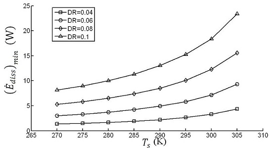
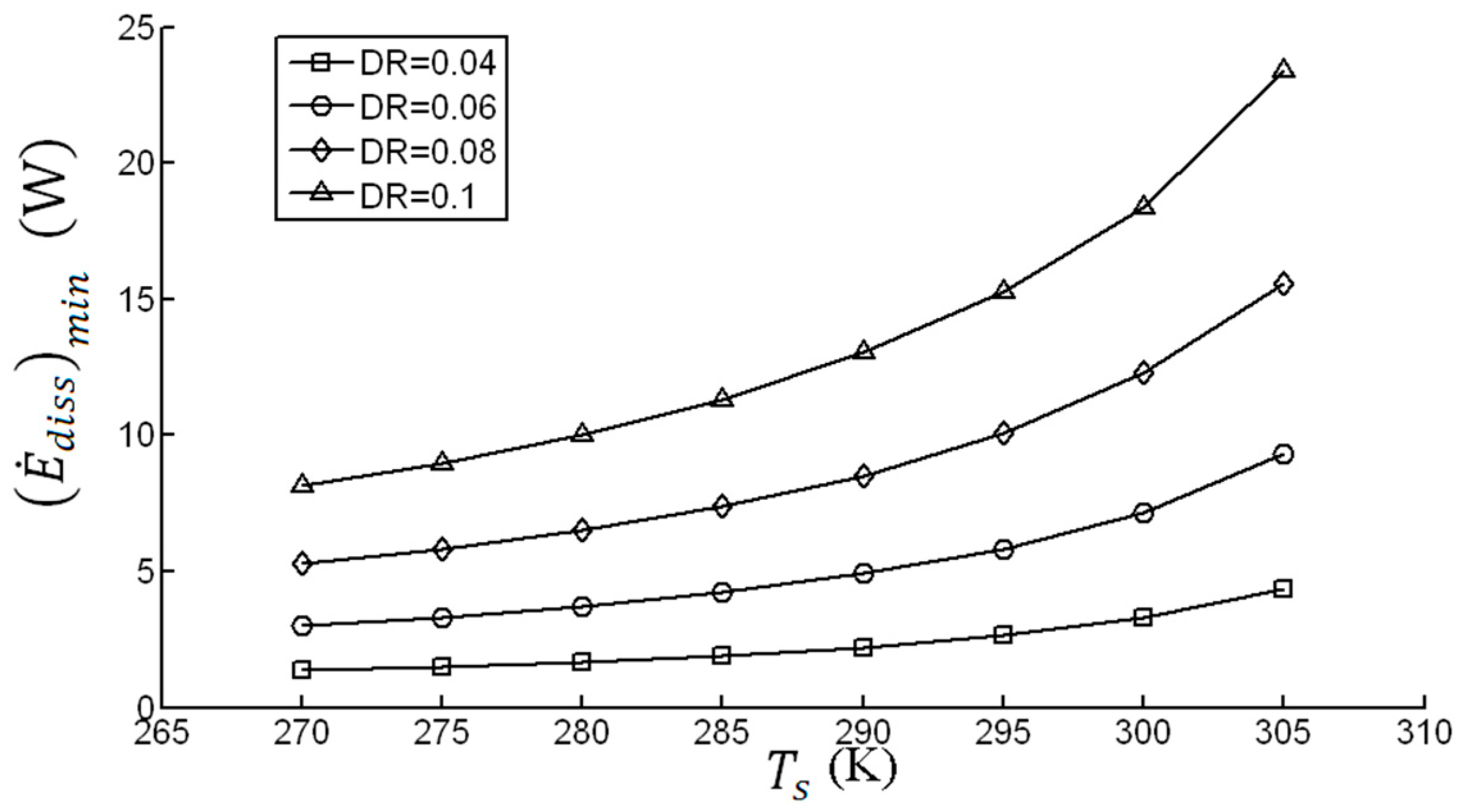
The design strategy, developed in the previous section and which is based on acoustic energy dissipation minimization, is applied to the model TAHX under study at different operating conditions. At various drive ratios and , the optimal configuration and its corresponding is determined, Figure 4. It can be seen that an increase of has a minor effect on at lower drive ratios; however, it has a major effect at larger drive ratios. To be exact, for a TAHX metal temperature of K, an increase of the drive ratio from 0.04 to 0.1 will increase six-fold the total dissipation.
The variation of with at different drive ratios is shown in Figure 5. It is evident that slightly decreases as increases. This decrease in has a lower magnitude at larger drive ratios. One may recall that as the TAHX metal temperature increases, the corresponding decreases—that is, the optimum diameter of the tube decreases. Theoretically, it is possible to obtain an optimum combination between the of the tube and TAHX metal temperature for a minimum acoustic power dissipation.
The variation of the heat exchanger surface area versus is plotted in Figure 6. It is evident that is proportional to and hence the acoustic power dissipated in the HX and so is nearly in proportion to . This result is in good agreement with the analysis in Section 2.1—that is, the thermal relaxation dissipation, which has the biggest impact in total dissipation in the HX, is proportional to .
3.3. The Influence of Drive Ratio (DR) on Acoustic Energy Dissipation
Further investigation is made on the impact of the drive ratio on the total acoustic energy dissipation, Figure 3a,b. A comparison between these figures reveals the strong dependency of the total acoustic energy dissipation on the drive ratio. Further, considering the drive ratio as an operating condition, analysis of the influence of drive ratio on the optimal TAHX configuration indicates the increase of the minimum energy dissipation with the drive ratio. This fact is clearly supported by the rearrangement of the previous results illustrated in Figure 7.
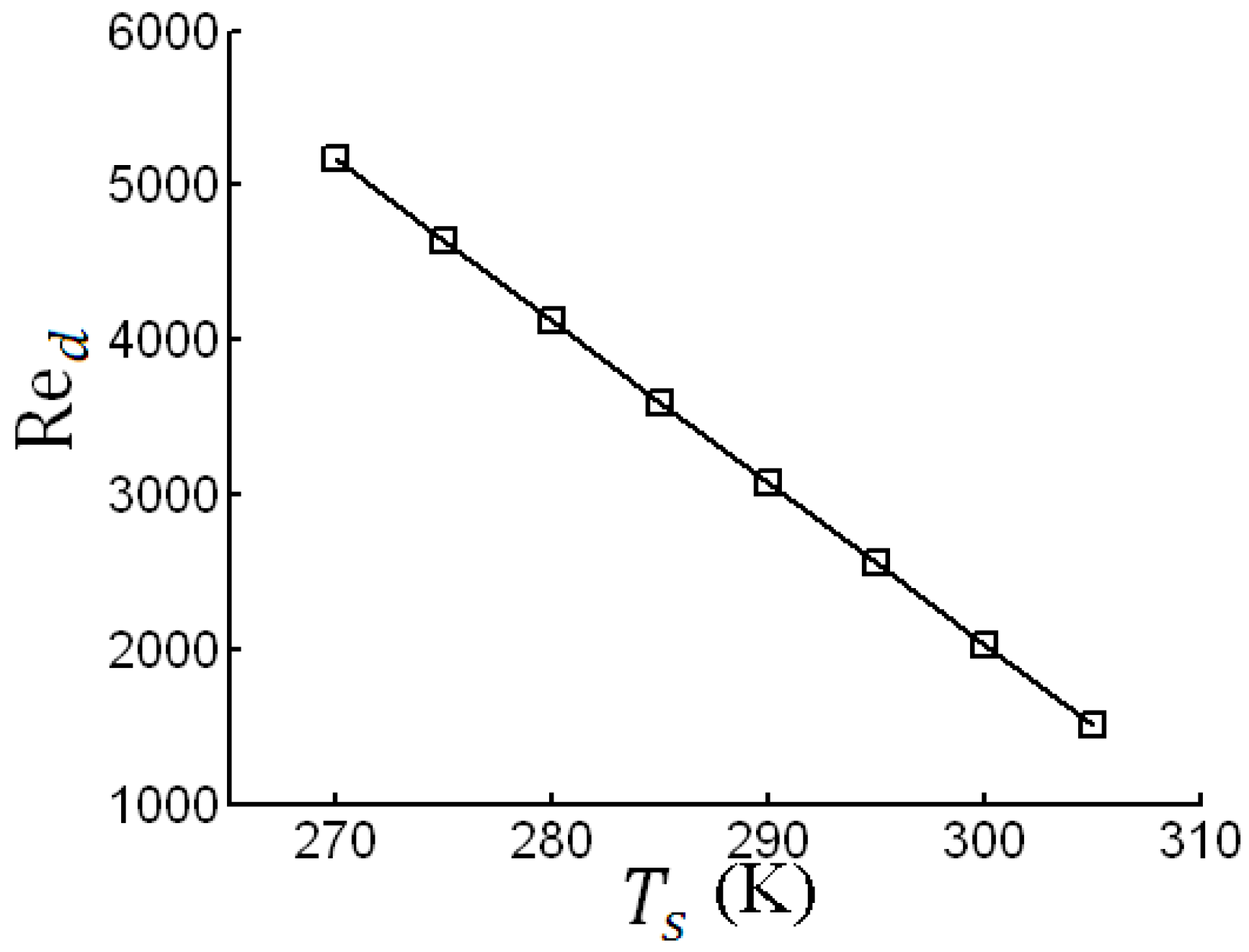
Finally, the variation of Reynolds number with TAHX metal temperatures is provided in Figure 8. As mentioned previously, one may specify the values for , , and to determine , the surface area of the HX. However, different HX configurations (,) might be designed to provide the same . Moreover, since the volume velocity of the gas entering the HX is constant for all the possible configurations, the volume velocity in each tube as well as changes. Nevertheless, remains constant at each and decreasing the temperature difference between the oscillating gas and the heat exchanger will result in a larger heat transfer area as shown in Figure 6. Further, the increment of heat transfer surface area is provided by increasing the number of tubes, consequently leading to a decrease of in correspondence with .
4. Conclusions
Today, thermoacoustic engines, coolers, and heat pumps are gaining more interest for commercialization. While thermoacoustic engines utilize heat to generate acoustic power, the thermoacoustic refrigerators consume the acoustic power to transfer heat from the cold reservoir. A key parameter in making thermoacoustic devices more competitive with classical products is the optimum design of the heat exchangers. Hence, a deeper knowledge of heat exchangers is required so that the gas mean temperature does not change along the flow oscillation and dissipate acoustic energy in the form of viscous and thermal relaxation while transferring the specified heat load.
This research is motivated by developing a simple but constructive methodology for comparison and evaluation of related heat exchangers with respect to acoustic energy dissipation, viscous loss, thermal relaxation loss, tube dimension, and drive ratio. In this paper, the performance of shell-and-tube TAHXs in the travelling-wave mode with ideal gases is investigated through a numerical model based on the classical linear thermoacoustic theory.
The results indicate that, at equal operating conditions, viscous dissipation and thermal relaxation dissipation have opposing behaviors. While decreases with , increases. Consequently, an optimum value of exists, denoted as , at which the total acoustic dissipation becomes a minimum, . The impact of the heat exchanger metal temperature on is also investigated. It is determined that, in general, increases with . Further, are obtained to be decreasing with metal temperature . In fact, heat transfer with minimum acoustic energy dissipation at lower temperature defects leads to . For example, at a drive ratio of 0.06 and metal temperature of 285, the minimum dissipation occurs around ; whereas at and higher, the minimum dissipation appears at relatively lower . The relation between the acoustic energy dissipation and the drive ratio for various is also presented. It is shown that the acoustic energy dissipation increases with the drive ratio. The growth rate, however, was lower for smaller values of .
The proposed model is able to put in evidence the strong dependence of the acoustic energy dissipation on both the diameter and the number of tubes and the existence of minima in correspondence with tube diameter normalized by thermal penetration depth. The different weight of the viscous and thermal losses affecting the HXs behavior is also highlighted with the second one dominating. Also important for design purposes is that acoustic energy dissipation minimization criterion can be effectively employed for the optimization of the configuration of the shell-and-tube TAHXs.
Acknowledgments
The present work has been supported in part by the office of research at Sharif University of Technology.
Author Contributions
Mohammad Gholamrezaei developed the algorithm, provided the results and wrote the draft. Kaveh Ghorbanian was in charge of technical examination and language proficiency. Both authors have read and approved the final manuscript.
Conflicts of Interest
The authors declare no conflict of interest.
Nomenclature
English letters:
| sound speed | (m·s−1) | |
| surface area | (m2) | |
| cross-sectional area of gas channels | (m2) | |
| tube outside diameters | (m) | |
| tube inside diameters | (m) | |
| drive ratio | - | |
| acoustic power dissipated | (W) | |
| acoustic power dissipated | (W) | |
| viscous dissipation of acoustic power | (W) | |
| thermal dissipation of acoustic power | (W) | |
| time averaged acoustic power | (W) | |
| spatially averaged diffusion function | - | |
| spatially averaged thermal diffusion function | - | |
| spatially averaged viscous diffusion function | - | |
| complex gain/attenuation constant for the volume flow rate | - | |
| shell-side heat transfer coefficient | (W·m−2·K−1) | |
| tube-side heat transfer coefficient | (W·m−2·K−1) | |
| gas thermal conductivity | (W·m−1·K−1) | |
| length of the tubes | (m) | |
| optimum length of thermoacoustic heat exchanger | (m) | |
| number of tube | - | |
| Acoustic pressure | (Pa) | |
| mean pressure | (Pa) | |
| heat transfer rate | (W) | |
| hydraulic diameter | (m) | |
| viscous resistance per unit length | (Pa·m−4·s) | |
| thermal resistance per unit length | (Pa·m−4·s) | |
| acoustic resistance per unit length | (Pa·m−4·s) | |
| tube side acoustic Reynolds number | - | |
| log-mean temperature | (K) | |
| gas temperature | (K) | |
| water outlet temperature | (K) | |
| water inlet temperature | (K) | |
| ambient temperature | (K) | |
| mean temperature | (K) | |
| oscillating volume flow rate | (m3·s) | |
| overall heat transfer coefficient | (W·m−2·K−1) | |
| overall heat transfer coefficient | (W·m−2·K−1) | |
| oscillating velocity | (m·s−1) |
Greek symbols:
| thermal penetration depth | (m) | |
| ratio of isobaric to isochoric specific heats | - | |
| thermal conductivity | (W·m−1·K−1) | |
| correction factor for finite solid heat capacity | - | |
| dynamic viscosity | (kg·m−1·s−1) | |
| density of the working gas | (kg·m−3) | |
| Prandtl number | - | |
| angular frequency | (s−1) | |
| minimum value of | (W) | |
| optimum value of | - |
Subscripts:
| dissipation | |
| mean | |
| minimum | |
| optimum | |
| thermal | |
| viscous | |
| 0 | “environment” or “ambient” |
| 1 | first order |
| 2 | second order |
References
- Swift, G.W. Thermoacoustic engines. J. Acoust. Soc. Am. 1988, 84, 1145–1180. [Google Scholar] [CrossRef]
- Backhaus, S.; Swift, G.W. A thermoacoustic Stirling heat engine: Detailed study. J. Acoust. Soc. Am. 2000, 107, 3148–3166. [Google Scholar] [CrossRef] [PubMed]
- Swift, G.W. Thermoacoustics: A Unifying Perspective for Some Engines and Refrigerators; Acoustical Society of America: Melville, NY, USA, 2002. [Google Scholar]
- Wu, F.; Wu, C.; Guo, F.; Li, Q.; Chen, L. Optimization of a Thermoacoustic Engine with a Complex Heat Transfer Exponent. Entropy 2003, 5, 444–451. [Google Scholar] [CrossRef]
- Zhibin, Y.; Jaworski, A.J. Impact of acoustic impedance and flow resistance on the power output capacity of the regenerators in travelling-wave thermoacoustic engines. Energy Conv. Manag. 2010, 51, 350–359. [Google Scholar]
- Tasnim, S.H.; Mahmud, S.; Fraser, R.A. Second law analysis of porous thermoacoustic stack systems. Appl. Therm. Eng. 2011, 31, 2301–2311. [Google Scholar] [CrossRef]
- Chaitou, H.; Nika, P. Exergetic optimization of a thermoacoustic engine using the particle swarm optimization method. Energy Conv. Manag. 2012, 55, 71–80. [Google Scholar] [CrossRef]
- Ishikawa, H.; Hobson, P.A. Optimization of heat exchanger design in a thermoacoustic engine using a second law analysis. Int. Commun. Heat Mass Transf. 1996, 23, 325–334. [Google Scholar] [CrossRef]
- Piccolo, A. Optimization of thermoacoustic refrigerators using second law analysis. Appl. Energy 2013, 103, 358–367. [Google Scholar] [CrossRef]
- Piccolo, A. Numerical Study of Entropy Generation Within Thermoacoustic Heat Exchangers with Plane Fins. Entropy 2015, 17, 8228–8239. [Google Scholar] [CrossRef]
- Swift, G.W.; Backhaus, S. A resonant, self-pumped, circulating thermoacoustic heat exchanger. J. Acoust. Soc. Am. 2004, 116, 2923–2938. [Google Scholar] [CrossRef]
- Incropera, F.P.; DeWitt, D.P.; Bergman, T.L.; Lavine, A.S. Introduction to Heat Transfer; John Wiley & Sons: Hoboken, NJ, USA, 2006. [Google Scholar]
- Ward, W.C.; Swift, G.W. Design environment for low-amplitude thermoacoustic engines. J. Acoust. Soc. Am. 1994, 95, 3671–3672. [Google Scholar] [CrossRef]
- Garret, S.L.; Perkins, D.K.; Gopinath, A. Thermoacoustic refrigerator heat exchangers: Design, analysis and fabrication. In Proceedings of the Tenth International Heat Transfer Conference, Brighton, UK, 14–18 August 1994; pp. 375–380.
- Swift, G.W. Analysis and performance of a large thermoacoustic engine. J. Acoust. Soc. Am. 1992, 92, 1551–1563. [Google Scholar] [CrossRef]
- Mozurkewich, G. Heat transfer from transverse tubes adjacent to a thermoacoustic stack. J. Acoust. Soc. Am. 2001, 110, 841–847. [Google Scholar] [CrossRef]
- Paek, I.; Braun, J.E.; Mongeau, L. Characterizing heat transfer coefficients for heat exchangers in standing wave thermoacoustic coolers. J. Acoust. Soc. Am. 2005, 118, 2271–2280. [Google Scholar] [CrossRef]
- Nsofor, E.C.; Celik, S.; Wang, X. Experimental study on the heat transfer at the heat exchanger of the thermoacoustic refrigerating system. Appl. Therm. Eng. 2007, 27, 2435–2442. [Google Scholar] [CrossRef]
- Kamsanam, W.; Mao, X.; Jaworski, A.J. Thermal performance of finned-tube thermoacoustic heat exchangers in oscillatory flow conditions. Int. J. Therm. Sci. 2016, 101, 169–180. [Google Scholar] [CrossRef]
Figure 1.
(a) of the HXs with different and at DR = 0.1; (b) of the HXs with different and (Zoom for Nt < 500).
Figure 1.
(a) of the HXs with different and at DR = 0.1; (b) of the HXs with different and (Zoom for Nt < 500).
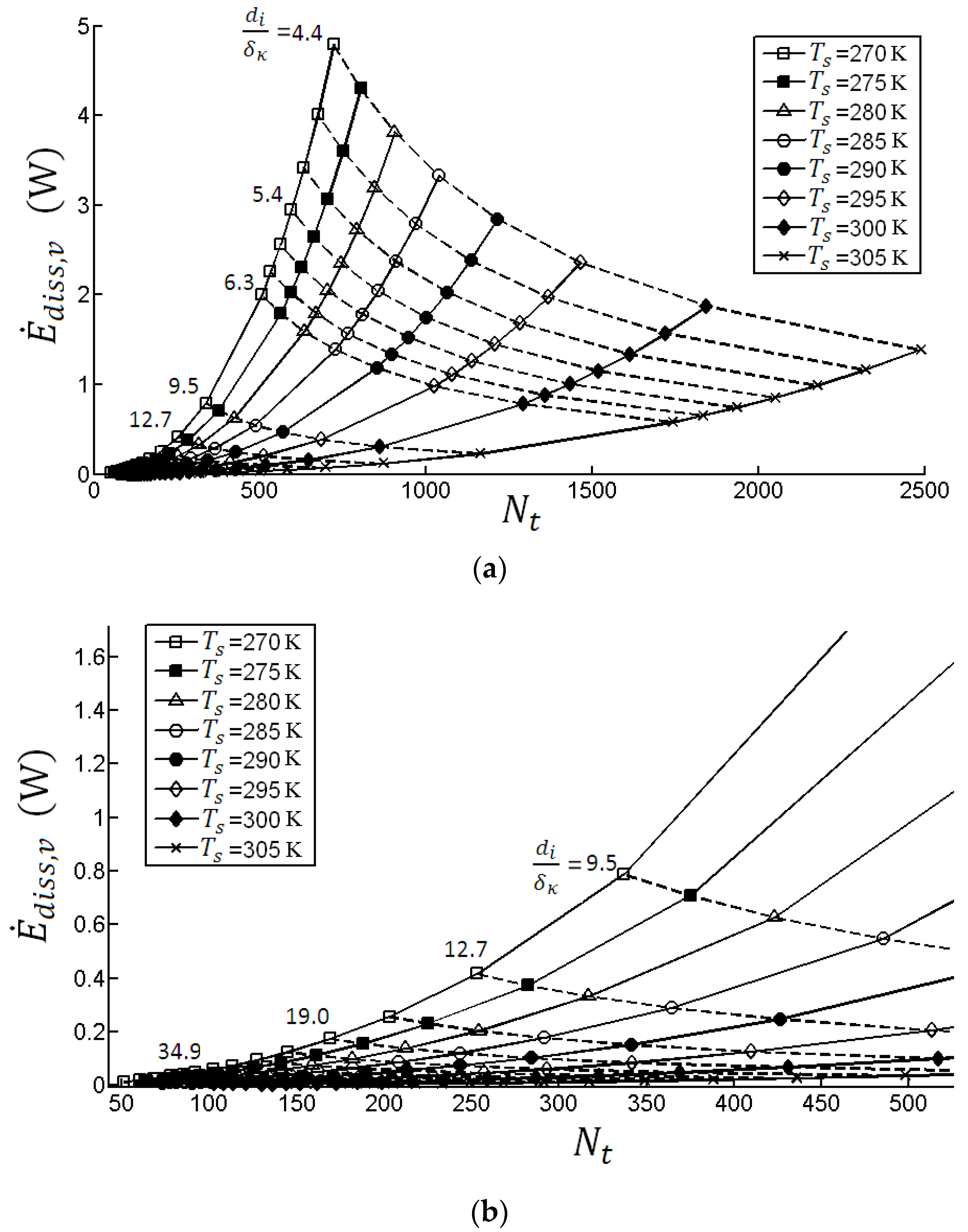
Figure 2.
of the HXs with different and at DR = 0.1.
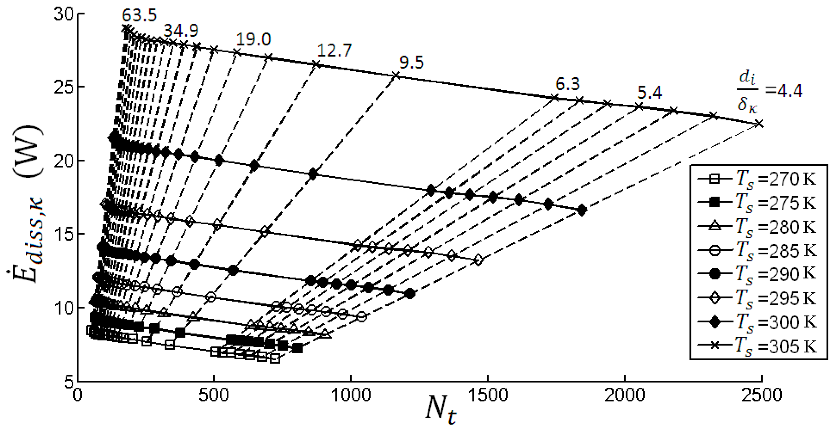
Figure 3.
of the HXs with different and (a) DR = 0.06; (b) DR = 0.1.
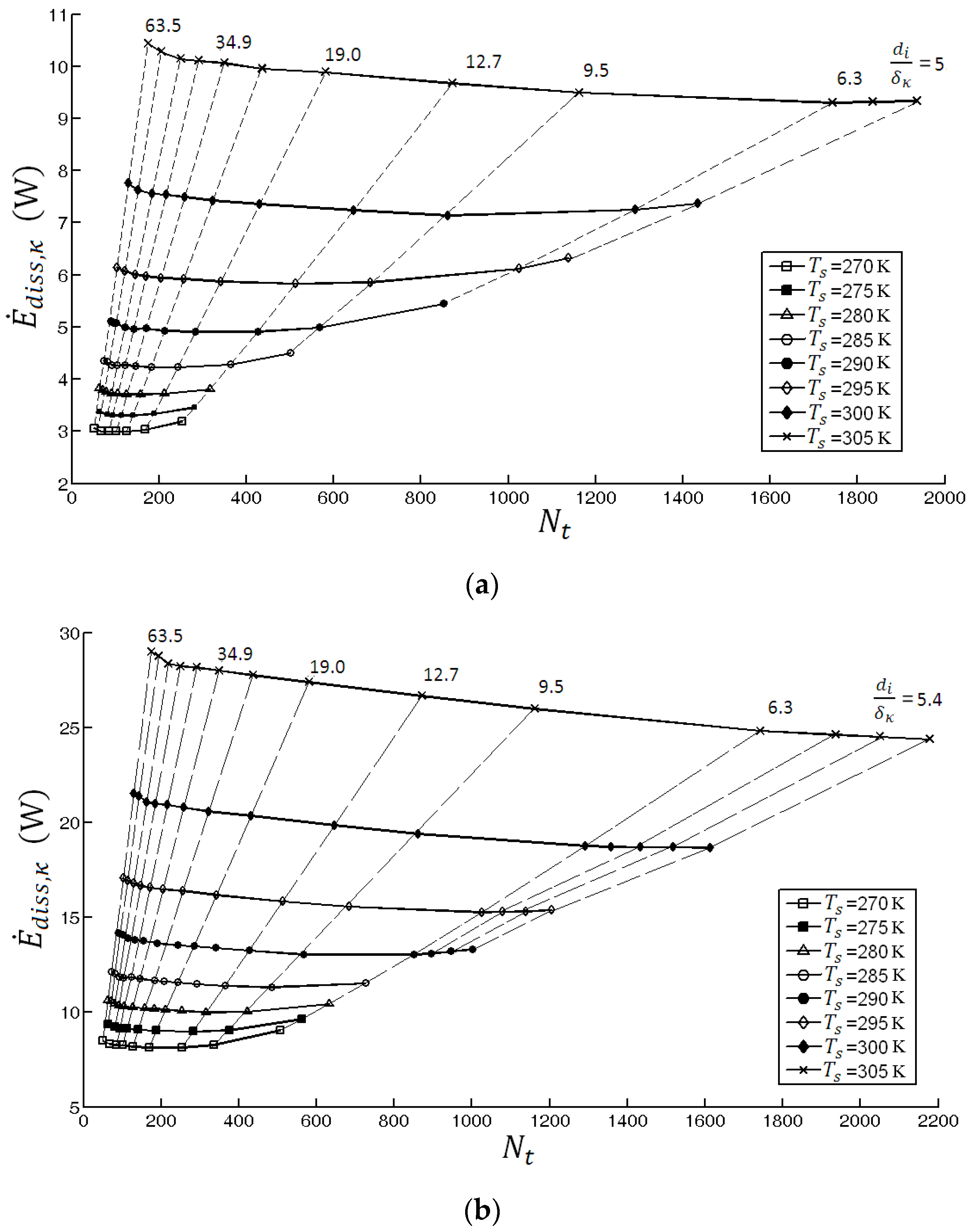
Figure 4.
at any .
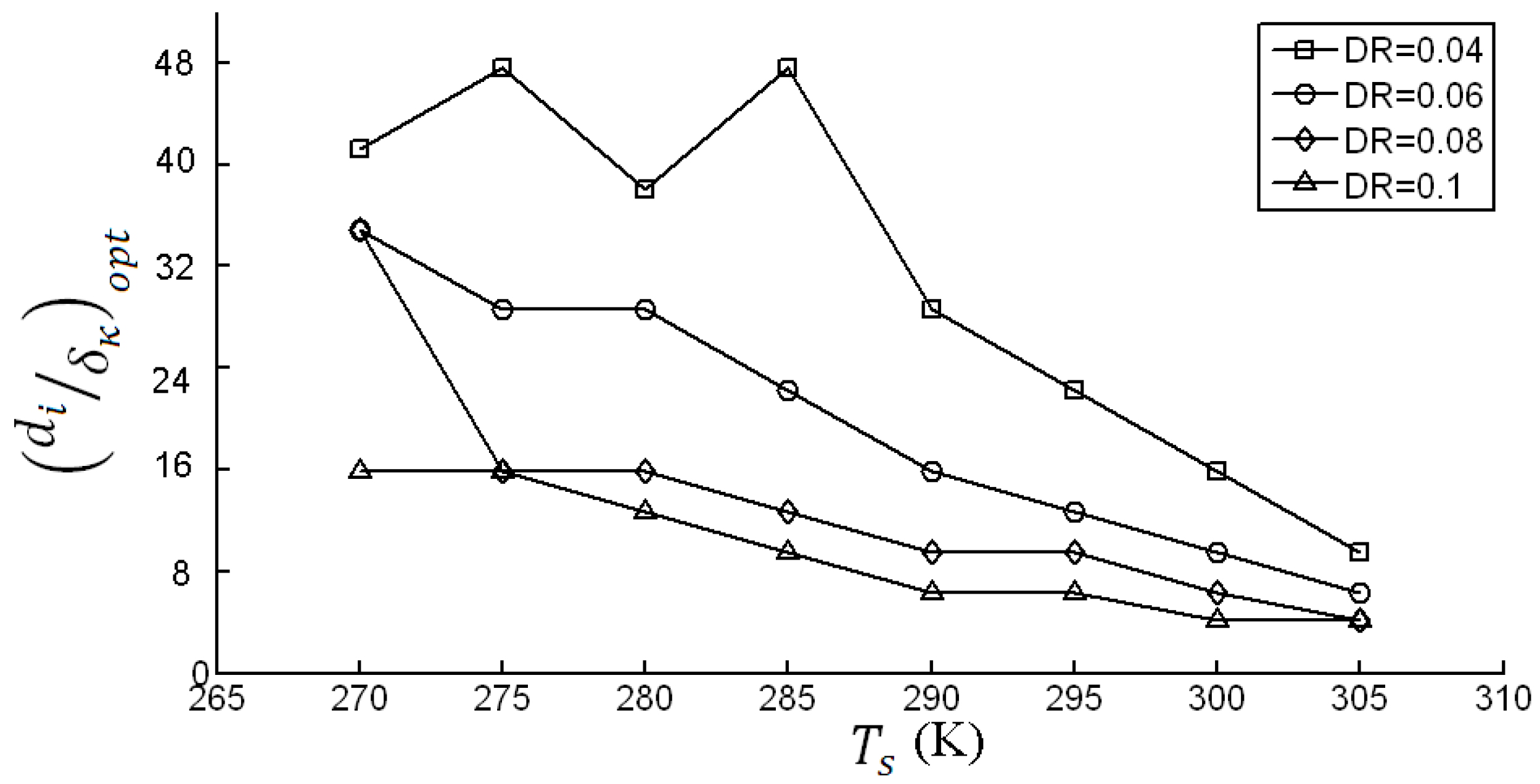
Figure 5.
at various .

Figure 6.
TAHX surface area variation with .
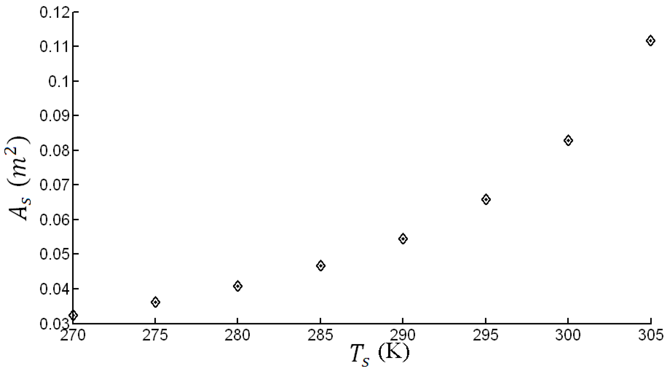
Figure 7.
variation with DR.
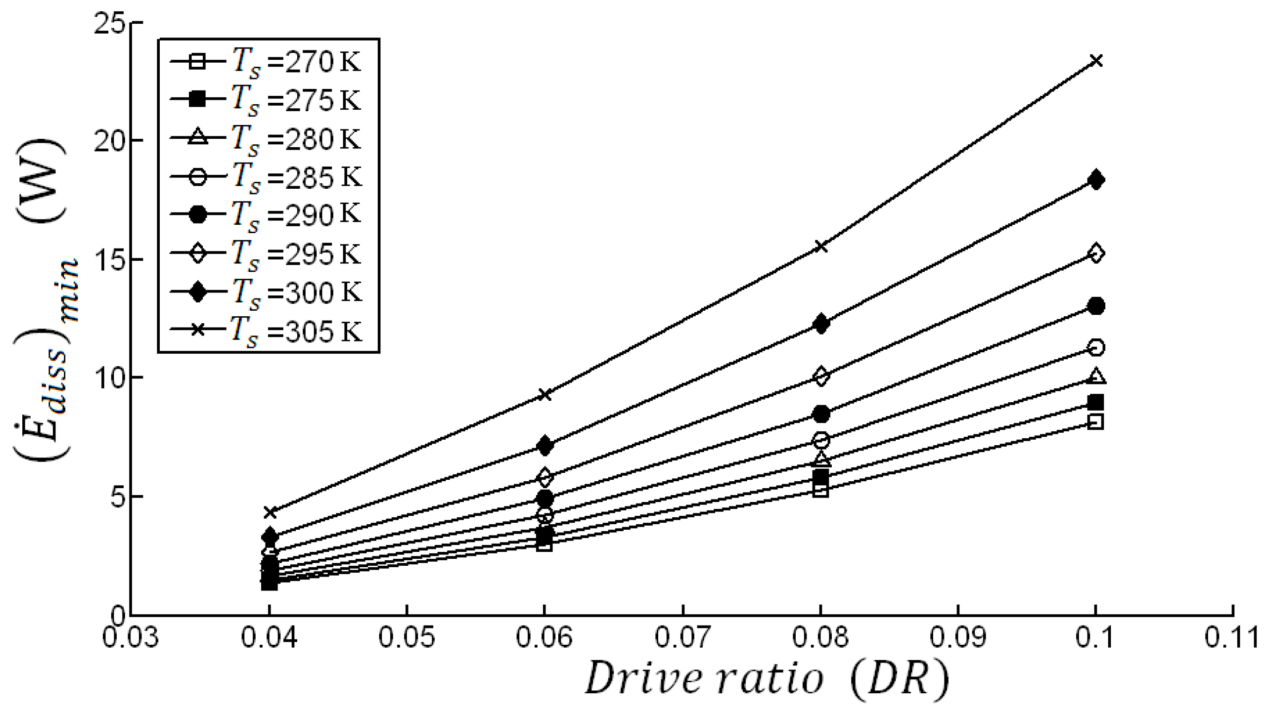
Figure 8.
variation with .


| Parameter | Symbol | Value | Units |
|---|---|---|---|
| Mean pressure | 3.1 | MPa | |
| Mean gas temperature | 319 | K | |
| Gas sound speed | 1060.8 | m/s | |
| Gas polytropic coefficient | 1.667 | - | |
| Gas Prandtl number | 0.428 | - | |
| Gas thermal conductivity | 0.159 | W/(m·K) | |
| Gas specific heat | 5193 | J/(kg·K) | |
| Gas kinematic viscosity | μ | 2.08 × 10⁻⁵ | kg/(s·m) |
| HX heat load | 1614 | W | |
| HX length | 20 | mm | |
| HX thermal conductivity | 14.858 | W/(m·K) | |
| HX specific heat | 464.89 | J/(kg·K) | |
| HX material density | 7909.1 | kg/m3 | |
| Operating frequency | 84 | Hz | |
| Gas thermal penetration depth | 0.157 | mm |
Table 2.
Comparison of the present model with experimental results of TAHX of TASHE [2] at DR = 0.1 and = 287 K.
| Parameter | Present Model | TAHX of TASHE [2] | Error (%) |
|---|---|---|---|
| Number of tubes () | 305 | 299 | 2% |
| Tubes diameter () | 2.4 mm | 2.5 mm | 4% |
| Acoustic energy dissipation | 11.7 | 12 W | 2.5% |
| (K) | (m2) | (-) | (W) | (-,mm) | (-) | (-) |
|---|---|---|---|---|---|---|
| 270 | 0.0325 | 5167.3 | 2.98 | (92,5.5) | 34.9 | 8.73 |
| 275 | 0.0361 | 4645.0 | 3.30 | (125,4.5) | 28.5 | 7.14 |
| 280 | 0.0408 | 4119.2 | 3.71 | (141,4.5) | 28.5 | 7.14 |
| 285 | 0.0467 | 3593.7 | 4.23 | (208,3.5) | 22.21 | 5.55 |
| 290 | 0.0543 | 3074.9 | 4.91 | (341,2.5) | 15.86 | 3.97 |
| 295 | 0.0658 | 2553.4 | 5.83 | (513,2) | 12.7 | 3.17 |
| 300 | 0.0829 | 2026.1 | 7.18 | (861,1.5) | 9.5 | 2.38 |
| 305 | 0.1118 | 1503.0 | 9.31 | (1742,1) | 6.3 | 1.59 |
| (K) | (m2) | (-) | (W) | (-,mm) | (-) | (-) |
|---|---|---|---|---|---|---|
| 270 | 0.0325 | 5167.3 | 8.12 | (203,2.5) | 3.97 | 15.8 |
| 275 | 0.0361 | 4645.0 | 8.95 | (225,2.5) | 3.97 | 15.8 |
| 280 | 0.0408 | 4119.2 | 9.99 | (317,2) | 3.17 | 12.7 |
| 285 | 0.0467 | 3593.7 | 11.30 | (485,1.5) | 2.38 | 9.5 |
| 290 | 0.0543 | 3074.9 | 13.03 | (567,1.5) | 2.38 | 9.5 |
| 295 | 0.0658 | 2553.4 | 15.25 | (1025,1) | 1.59 | 6.3 |
| 300 | 0.0829 | 2026.1 | 18.37 | (1986,0.065) | 1.03 | 4.1 |
| 305 | 0.1118 | 1503.0 | 23.40 | (2680,0.065) | 1.03 | 4.1 |
© 2016 by the authors; licensee MDPI, Basel, Switzerland. This article is an open access article distributed under the terms and conditions of the Creative Commons Attribution (CC-BY) license (http://creativecommons.org/licenses/by/4.0/).
Share and Cite
MDPI and ACS Style
Gholamrezaei, M.; Ghorbanian, K. Thermal Analysis of Shell-and-Tube Thermoacoustic Heat Exchangers. Entropy 2016, 18, 301. https://doi.org/10.3390/e18080301
AMA Style
Gholamrezaei M, Ghorbanian K. Thermal Analysis of Shell-and-Tube Thermoacoustic Heat Exchangers. Entropy. 2016; 18(8):301. https://doi.org/10.3390/e18080301
Chicago/Turabian StyleGholamrezaei, Mohammad, and Kaveh Ghorbanian. 2016. "Thermal Analysis of Shell-and-Tube Thermoacoustic Heat Exchangers" Entropy 18, no. 8: 301. https://doi.org/10.3390/e18080301
Note that from the first issue of 2016, this journal uses article numbers instead of page numbers. See further details here.