Article

General Approach for Composite Thermoelectric Systems with Thermal Coupling: The Case of a Dual Thermoelectric Cooler

Instituto Politecnico Nacional, SEPI ESIME-CUL, Av. Santa Ana 1000, Culhuacan, Coyoacan 04430,Mexico
*
Author to whom correspondence should be addressed.
Entropy 2015, 17(6), 3787-3805; https://doi.org/10.3390/e17063787
Submission received: 17 April 2015 / Accepted: 3 June 2015 / Published: 8 June 2015
(This article belongs to the Section Thermodynamics)

Abstract

:
In this work, we show a general approach for inhomogeneous composite thermoelectric systems, and as an illustrative case, we consider a dual thermoelectric cooler. This composite cooler consists of two thermoelectric modules (TEMs) connected thermally in parallel and electrically in series. Each TEM has different thermoelectric (TE) properties, namely thermal conductance, electrical resistance and the Seebeck coefficient. The system is coupled by thermal conductances to heat reservoirs. The proposed approach consists of derivation of the dimensionless thermoelectric properties for the whole system. Thus, we obtain an equivalent figure of merit whose impact and meaning is discussed. We make use of dimensionless equations to study the impact of the thermal conductance matching on the cooling capacity and the coefficient of the performance of the system. The equivalent thermoelectric properties derived with our formalism include the external conductances and all intrinsic thermoelectric properties of each component of the system. Our proposed approach permits us changing the thermoelectric parameters of the TEMs and the working conditions of the composite system. Furthermore, our analysis shows the effect of the number of thermocouples on the system. These considerations are very useful for the design of thermoelectric composite systems. We reproduce the qualitative behavior of a commercial composite TEM connected electrically in series.

1. Introduction

Composite thermoelectric systems, based on thermoelectric effects, such as Seebeck effect and Peltier effect, have a variety of uses nowadays. A composite thermoelectric cooling system (composite TECS) has many advantages in comparison with the traditional cooling systems, such as the lack of moving parts, low weight, does not need maintenance and the fact that it is environmentally friendly due to lack of cooling substances. Disadvantage of the TECS are the low cooling capacity Qc and coefficient of performance (COP). New techniques and thermoelectric materials have been proposed for designing new thermoelectric specific systems that allow the improvement of the device performance through the optimization of the thermal and electrical transport properties [13]. These TECS, known as solid-state devices, are used in many different applications, ranging from controlling the temperature of laser diodes, infrared detectors, superconductor applications, aerospace applications, electronic devices and food storage [4].
It is well known that the thermal conductance of ceramic plates plays a vital role in the performance of TECS. Yamanashi [5] has considered the effects of the thermal resistance of heat exchangers on the performance of a TEC, with a constant thermocouple number. He has obtained the design parameters through the dimensionless heat balance equations. On the other hand, Xuan [6], through introducing equivalent impedances to take into account the thermal contact effect of a single stage, have derived the maximum temperature difference, cooling capacity and COP. Recently, Pearson and Lents [7] have studied a thermal network with an integrated TEC and performed a dimensionless analysis. They concluded that dimensionless parameters reduce the complexity of the results, enabling the evaluation of the system without knowing the detailed information of the geometries or the materials. These proposals consider homogeneous TECS, i.e., TECS with thermoelectric modules (TEMs) that have the same thermoelectric properties, namely the Seebeck coefficient, electrical resistance and thermal conductance. However, the behavior of inhomogeneous composite TECS, i.e., composite TECS with TEMs that have different thermoelectric properties, can not be predicted.
Apertet et al. [8] have considered an inhomogeneous thermoelectric generator system (TEGS) composed of two different thermoelectric modules, electrically and thermally connected in parallel, using linear irreversible thermodynamics, and they have proposed equivalent parameters for an equivalent thermoelectric generator system, including realistic thermal coupling [9]. Using this linear approach, others authors [10,11] have considered different configurations for composite TEGS.
Moreover, a widely-considered approach in the analysis for both TECS and TEGS is Ioffe’s approach [12]. This approach includes the Joulean heat loss [5,6]. Thus, we are interested in the analysis of inhomogeneous composite TECS, and we propose a general approach, based in Ioffe’s approach, which includes all thermoelectric properties of the TEMs constituting the TECS. We illustrate this general approach for a dual thermoelectric cooling system that consists of two TEMs with different thermoelectric properties and thermal coupling. This approach can be useful for designing a composite solid-state device with thermal coupling for switching between low power consumption or high heat pumping performance [13].
The paper is organized as follows: In Section 2, we present the configuration of the dual thermoelectric cooler system. We derive the equivalent parameters for our system and transform it into its dimensionless form, in Section 3. In Section 4, we analyze our numerical results for COP and for cooling capacity, QC, and their behavior as a function of the thermal impedances. Finally, in Section 5, we present our conclusions, and future work is discussed briefly.

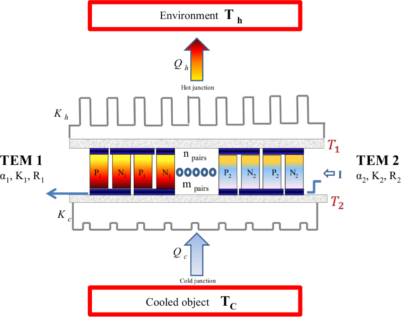
2. Dual Thermoelectric Cooling System

Our composite TEC system is composed of two thermoelectric modules thermally connected in parallel and electrically connected in series, as depicted in Figure 1. The system is coupled to two heat reservoirs by thermal exchangers, and the temperatures of the heat reservoirs are Tc and Th with Th > Tc. Kc and Kh are the thermal conductances of the heat exchangers at both sides, cold and hot, respectively. Each TEM is characterized by a Seebeck coefficient αi, thermal conductance Ki and an electrical resistanceRi, where i can be one or two as appropriate. The TEM1 and TEM2 are formed by m and n thermocouples number, respectively. I is the electrical current through the TEMs.

3. Heat Balance Equations

We assume that the heat flow between the TEMs and the surroundings is ignored, except for the cold and hot end of each TEM; also, the properties of the N- and P -type elements are assumed independent of temperature. In Figure 1, Qh is the heat rejected from the TEC system to the heat reservoir and Qc is the cooling capacity or the heat absorbed from the cooled object. Assuming that the heat flow between each stage and the heat reservoirs obey Newton’s law, we have:
Q h = K h ( T 1 T h )
Q c = K c ( T c T 2 )
The heat flux flowing through the dual TEC system is the sum of two heat fluxes flowing through TEM1 and TEM2,
Q h = Q h 1 + Q h 2
Q c = Q c 1 + Q c 2
The heat fluxes, Qci and Qhi (i = 1, 2), for each TEM are given by:
Q h 1 = m [ α 1 I T 1 + 1 2 I 2 R 1 K 1 ( T 1 T 2 ) ]
Q c 1 = m [ α 1 I T 2 1 2 I 2 R 1 K 1 ( T 1 T 2 ) ]
Q h 2 = n [ α 2 I T 1 + 1 2 I 2 R 2 K 2 ( T 1 T 2 ) ]
Q c 2 = n [ α 2 I T 2 1 2 I 2 R 2 K 2 ( T 1 T 2 ) ]
where m and n are the number of thermocouples for TEM1 and TEM2, respectively. Equations (5)(8) contain three terms, namely αIT, Peltier heat, I2R, the internal heat generated by the Joulean loss and K(T1T2), conduction heat loss. Clearly, the properties of different thermoelectric semiconductor materials of each TEM are included in the above equations.

3.1. Equivalent Dual TEC System

In this section, we derive the equivalent thermoelectric parameters of the dual TEC system as a whole. Combining Equations (1)(3), (5) and (7), we obtain for the heat rejected, Qh,
Q h = α e q H I T h + 1 2 I 2 R e q H K e q H ( T h T c )
where,
α e q H = ( m α 1 + n α 2 ) ( 1 + m α 1 I + n α 2 I K c ) 1 + ( m K 1 + n K 2 ) ( K c + K h ) K h K c + ( m α 1 I + n α 2 I ) ( K h K c ) K h K c ( m α 1 I + n α 2 I ) 2 K h K c
R e q H = ( m R 1 + n R 2 ) ( 1 + m α 1 I + n α 2 I K c + 2 m K 1 + n K 2 K c ) 1 + ( m K 1 + n K 2 ) ( K c + K h ) K h K c + ( m α 1 I + n α 2 I ) ( K h K c ) K h K c ( m α 1 I + n α 2 I ) 2 K h K c
K e q H = ( m K 1 + n K 2 ) 1 + ( m K 1 + n K 2 ) ( K c + K h ) K h K c + ( m α 1 I + n α 2 I ) ( K h K c ) K h K c ( m α 1 I + n α 2 I ) 2 K h K c
Similarly, combining Equations (1), (2), (4), (6) and (8), we have for absorbed heat Qc,
Q c = α e q C I T c 1 2 I 2 R e q C K e q C ( T h T c )
where:
α e q C = ( m α 1 + n α 2 ) ( 1 m α 1 I + n α 2 I K h ) 1 + ( m K 1 + n K 2 ) ( K c + K h ) K h K c + ( m α 1 I + n α 2 I ) ( K h K c ) K h K c ( m α 1 I + n α 2 I ) 2 K h K c
R e q C = ( m R 1 + n R 2 ) ( 1 m α 1 I + n α 2 I K h + 2 m K 1 + n K 2 K h ) 1 + ( m K 1 + n K 2 ) ( K c + K h ) K h K c + ( m α 1 I + n α 2 I ) ( K h K c ) K h K c ( m α 1 I + n α 2 I ) 2 K h K c
K e q C = ( m K 1 + n K 2 ) 1 + ( m K 1 + n K 2 ) ( K c + K h ) K h K c + ( m α 1 I + n α 2 I ) ( K h K c ) K h K c ( m α 1 I + n α 2 I ) 2 K h K c
The equivalent thermoelectric parameters of our dual TEC system are given by Equations (10)(12) and (14)(16). These equations generalize the previously obtained results for homogeneous thermoelectric cooling systems considered by other authors [6]. For example, the parameters αeqH and αeqC are the effective Seebeck coefficients for the hot and cold side, respectively. These equivalent parameters not only combine all intrinsic thermoelectric properties of both modules, but also they are significantly influenced by external thermal conductances. In Section 4.4, we will show that the numerical behavior of the figure of merit for the whole system satisfies Bergman’s theorem. Notice that the equivalent heat balance equations of the system (9) and (13), depend only on the temperatures Tc and Th. Furthermore, we will use these results and recover, as limit cases, the design parameters for TEC system, which have been previously studied by other authors; see Section 4.5.

3.2. Dimensionless Equivalent Heat Balance Equations

When a TEC system is optimized, it is convenient to rewrite the heat balance Equations (9) and (13), into the dimensionless form as follows [5],
q h = φ 1 + φ δ μ + 1 2 φ 2 1 Z e q T h 1 + φ δ + 2 δ μ 1 θ μ
q c = φ 1 φ ρ μ 1 2 φ 2 1 Z e q T c 1 φ ρ + 2 ρ μ 1 θ 1 μ
where dimensionless quantities are defined as,
θ = T c T h
δ = ( m K 1 + n K 2 ) K c
ρ = ( m K 1 + n K 2 ) K h
φ = I ( m α 1 + n α 2 ) ( m K 1 + n K 2 )
Z e q = ( m α 1 + n α 2 ) 2 ( m R 1 + n R 2 ) ( m K 1 + n K 2 )
q h = Q h ( m K 1 + n K 2 ) T h
q c = Q c ( m K 1 + n K 2 ) T c
μ = 1 + δ + ρ + ( δ ρ ) φ φ 2 δ ρ
In equations (17) and (18), the dimensionless current is represented by φ. The parameters δ and ρ are dimensionless thermal conductances normalized by the cold and hot external thermal conductances, respectively. θ is the temperature ratio of heat reservoirs. Zeq is the equivalent figure of merit and µ is a coupling factor. Notice that we recover the dimensionless quantities qh and qc, which have been considered as the entropy flow normalized by the intrinsic thermal conductances, mK1 + nK2, of the inhomogeneous TEC system.
The equivalent figure of merit Zeq, Equation (23), can be written in terms of the number of pairs of each TEM as:
Z e q = α 1 2 ( D + Z r ) 2 R 1 K 1 ( D + Z r ) 2 = Z 1 ( D + Z r ) 2 ( D + Z r ) 2
where the number of pairs ratio, D, and the figure of merit ratio, Zr, are given by:
D = m n
Z r = Z 1 Z 2
Now, the well-known COP for a cooling system,
C O P = Q c Q h Q c
can be written in terms of dimensionless heat quantities,
C O P = q c 1 θ q h q c
We point out that this approach can be used in the analysis of a thermoelectric heat pump.

4. Results and Discussion

In this section, we study the effect of the thermal conductance matching on the cooling capacity qc and the COP of the TEC system. In our calculations, we use values Tc = 286K and Th = 296K for the temperatures of the cold and hot reservoirs, respectively.

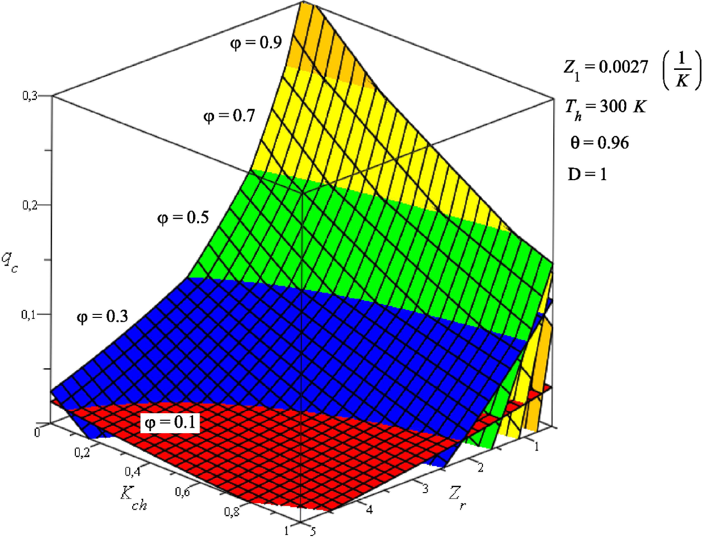
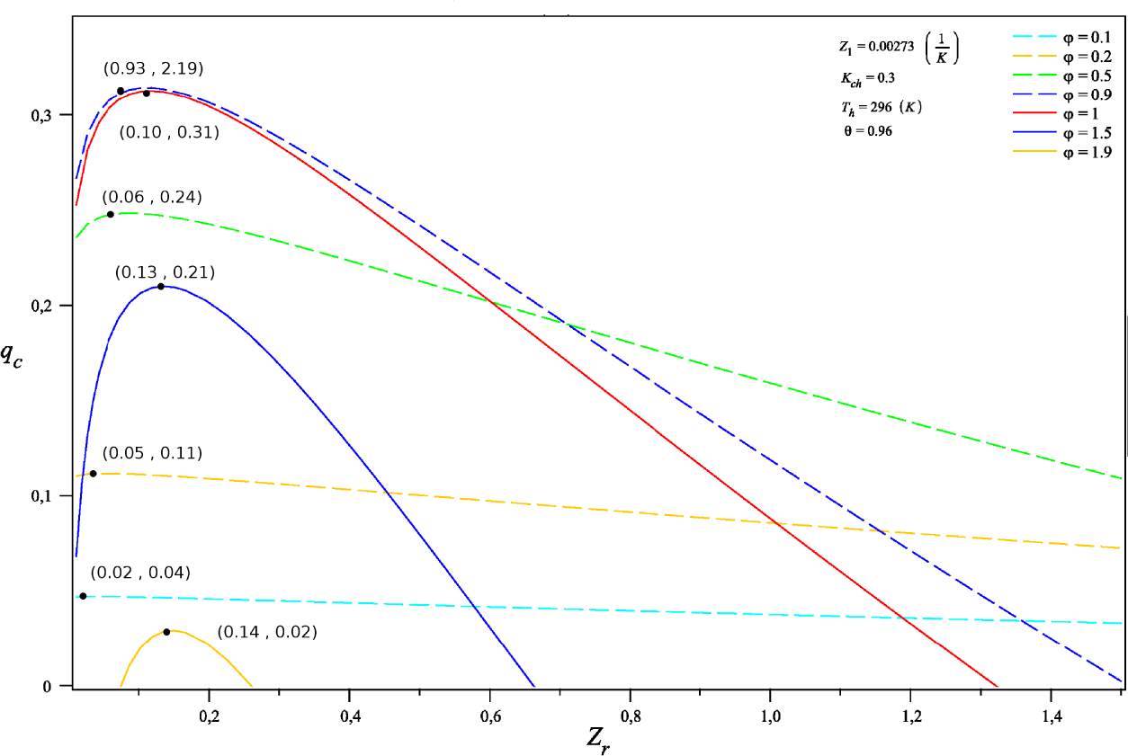
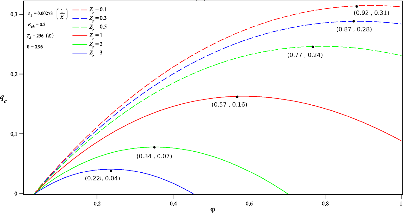
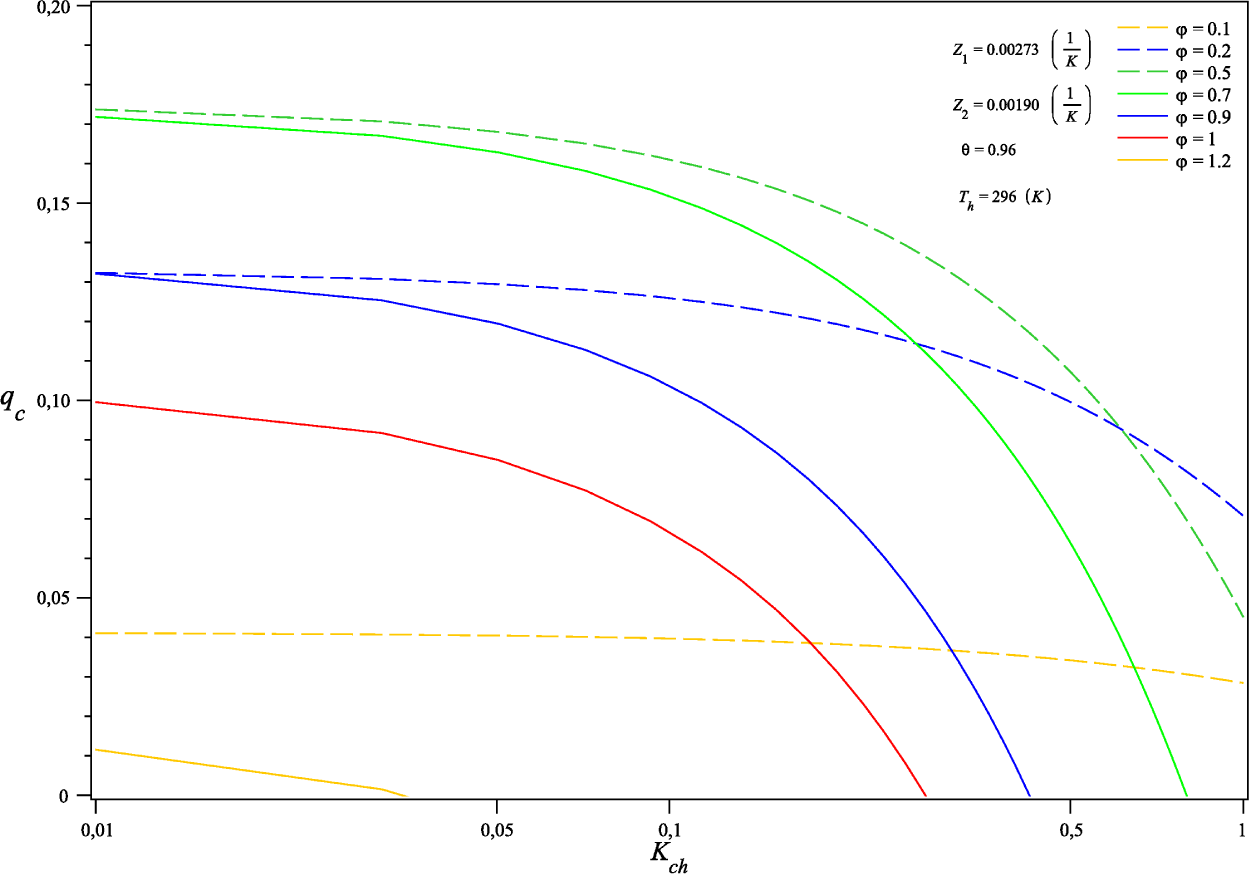
4.1. Cooling Capacity qc: External Conductances Match

The behavior of the cooling capacity and the COP as a function of the dimensionless current, φ, for different external conductance ratios,
K c h = K c K h
are shown by Figures 2 and 6, respectively (see also Figures 11, 13 in Appendix).
Figure 2 shows that a limit value of qc is reached as the ratio Kch decreases for a given value of φ when Kc < Kh. As the external conductance ratio decreases, the change in maximal values of the cooling capacity are determined by the electrical current φ. Moreover, the limit values of qc are determined by the ratio Kch. Thus, the condition Kc < Kh is bounded, because qc will reach limit values. Notice that it is possible to reach the same limit value of qc, using different values of electrical current, φ.
From the results obtained in Section 3, our approach permits us to calculate the cooling capacity, qc, in terms of any two thermoelectric parameters (φ, Kch, Zr) of the equivalent TEC system. For example, Figure 3 shows the behavior of qc as a function of the figure of merit ratio Zr and external conductances ratio, Kch, for different values of electrical current, φ.
Notice that the behavior of qc includes several effects that are contained in different planes of Figure 3. For example, maximum values for cooling capacity qc are shown in the plane qc vs. Zr, at different values of electrical current φ, for small figure of merit ratios, Zr, and thermal conductances ratios, Kch. This result is more clearly shown in Figure 4.
Our approach permits us to know the effect of (1) thermal conductances, Kch, and (2) the figure of merit ratio, Zr, on the cooling capacity qc at different working conditions. These effects are shown in Figures 11 and 12 of the Appendix.
Furthermore, we show the effect on qc of both φ and Zr, in Figure 5, for a given value of Kch.
In fact, Figure 5 shows the optimal values of qc in terms of φ and Zr for constant values of other parameters, namely Z1, Th, θ, Kch and D, which determine the working conditions of the composite TEC system.
We point out that our proposed approach permits us to change the thermoelectric parameters of the TEMs and the working conditions of the composite system. This fact is very useful for the design of thermoelectric composite systems.

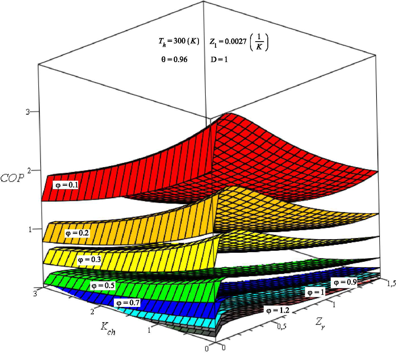
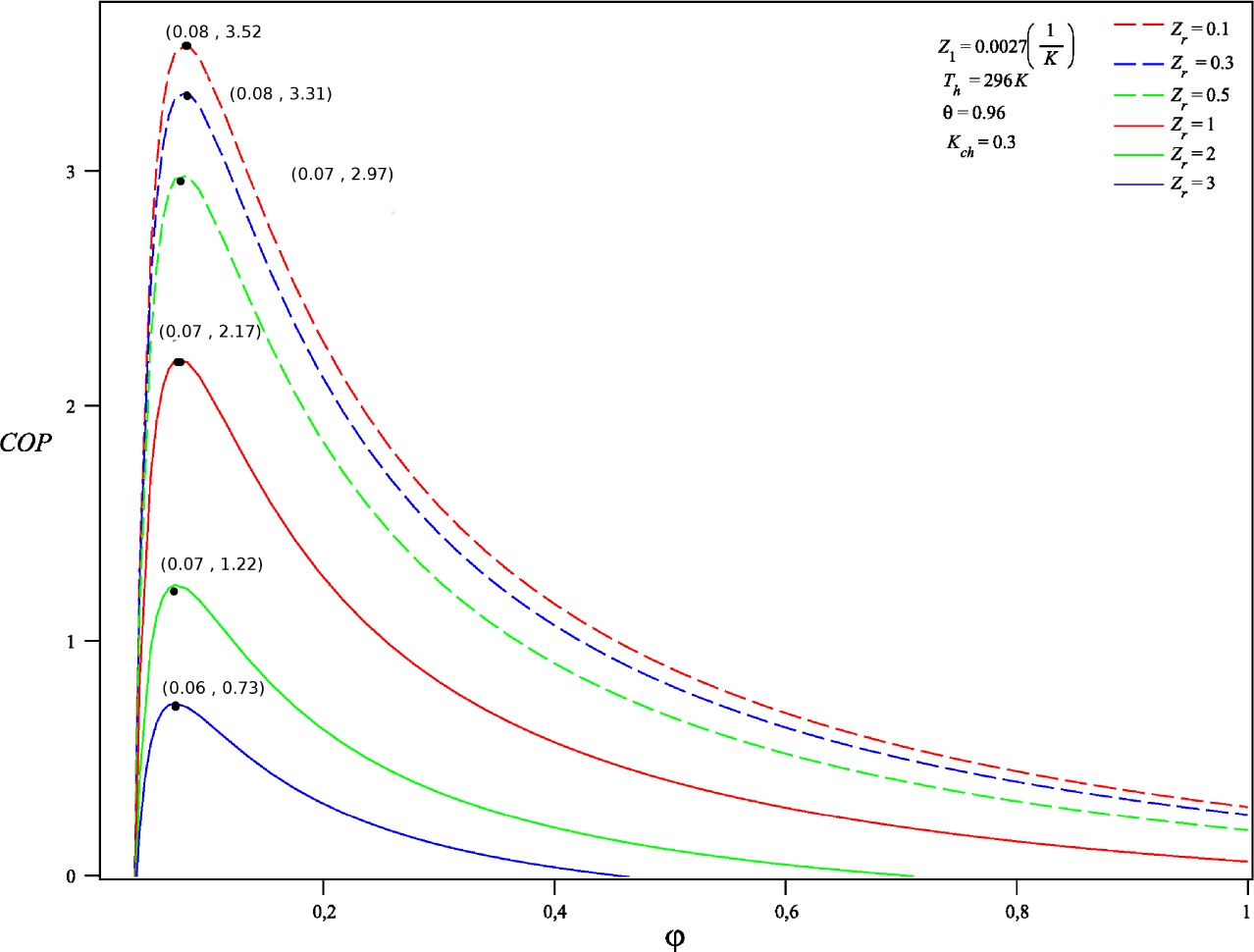
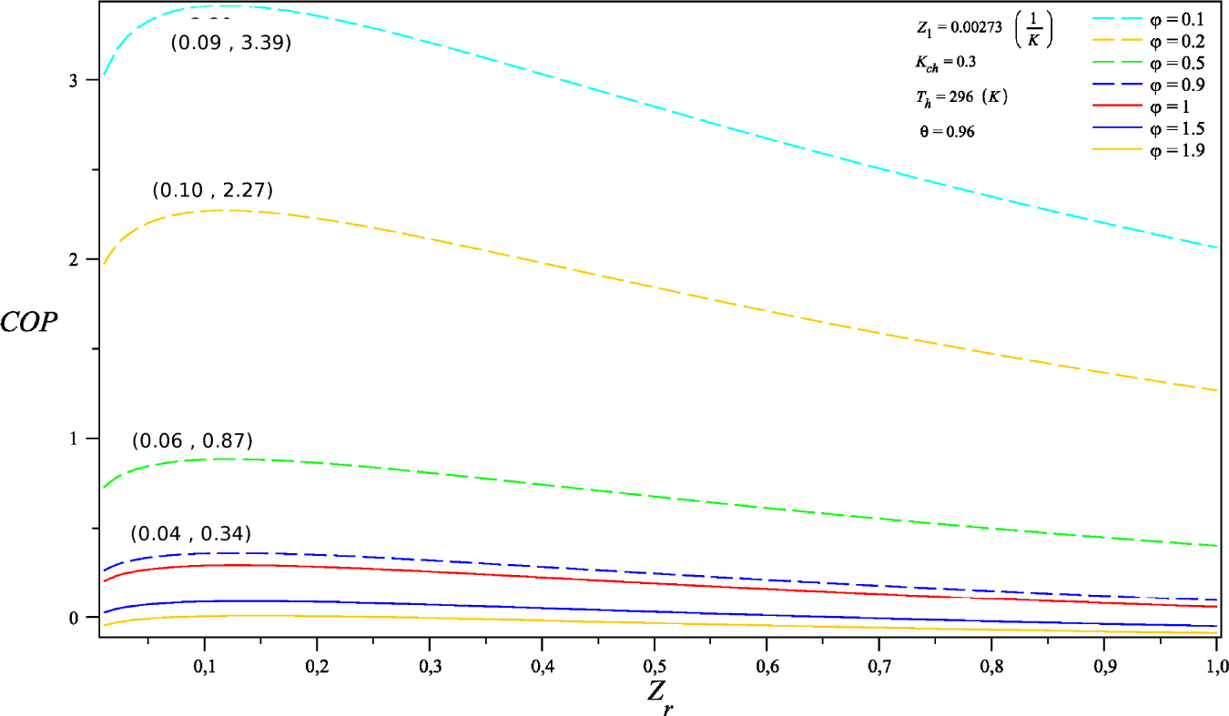
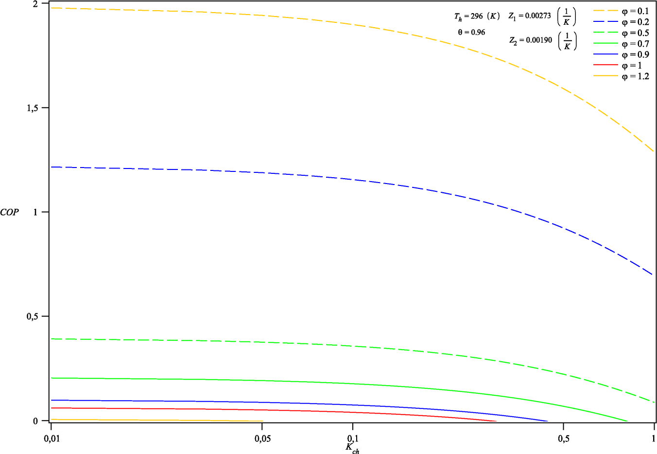
4.2. Coefficient of Performance (COP): External Conductances Match

Analogously, Figures 6, 7 and 8 show the corresponding behavior for COP of the system as a function of Kch, Zr and φ, respectively.
Again, we obtain several results for COP of the system, which are included in different planes of Figures 7 and 8. See Figures 13, 14 and 15 in the Appendix.
For example, Figures 6 and 13 show that the maximal values of the COP tend to a limit maximum value as the ratio Kch changes. This fact shows that it is not possible to optimize the system by just fixing the Kch, but also a limit for the external conductances Kch exists. Table 1 shows the behavior of limit values for COP as we change the ratio Kch.
As is well known, the optimal working conditions are different for both maximum values of qc and COP. A maximum value for qc is obtained for high values of φ; meanwhile, the maximum values of COP are obtained in low ranges of φ. In Section 4.3, we obtain the qualitative behavior of COP for a commercial composite TEM connected in series.

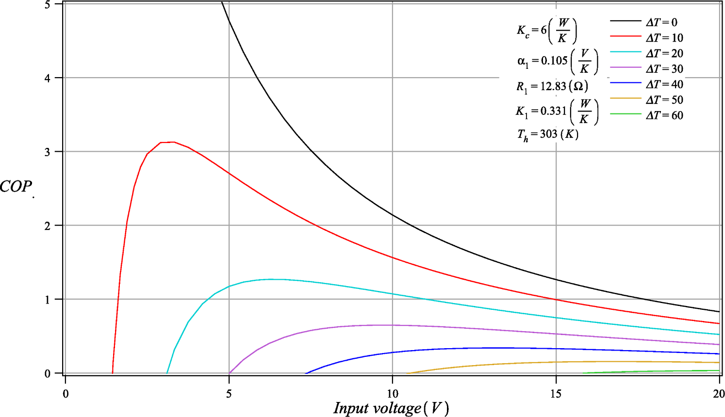
4.3. Numerical Validation

Firstly, Table 2 shows some values of Kch, δ and ρ used in our calculations, only for completeness reasons.
Nowadays, it is possible to fabricate composite TEMs connected in different configurations [13,14]. We use the thermoelectric parameters, α1 = α2 = αLuo, R1 = R2 = RLuo and K1 = K2 = KLuo, for a composite TEM connected in series proposed by Luo [15] for obtaining Figure 9. The behavior of the COP, shown in Figure 9, is very near to that reported in the datasheet for the SP − 254 − 1.0−2.5 (series) TEM connected electrically in series, with the same thermoelectric properties for each component of the TEM [16].

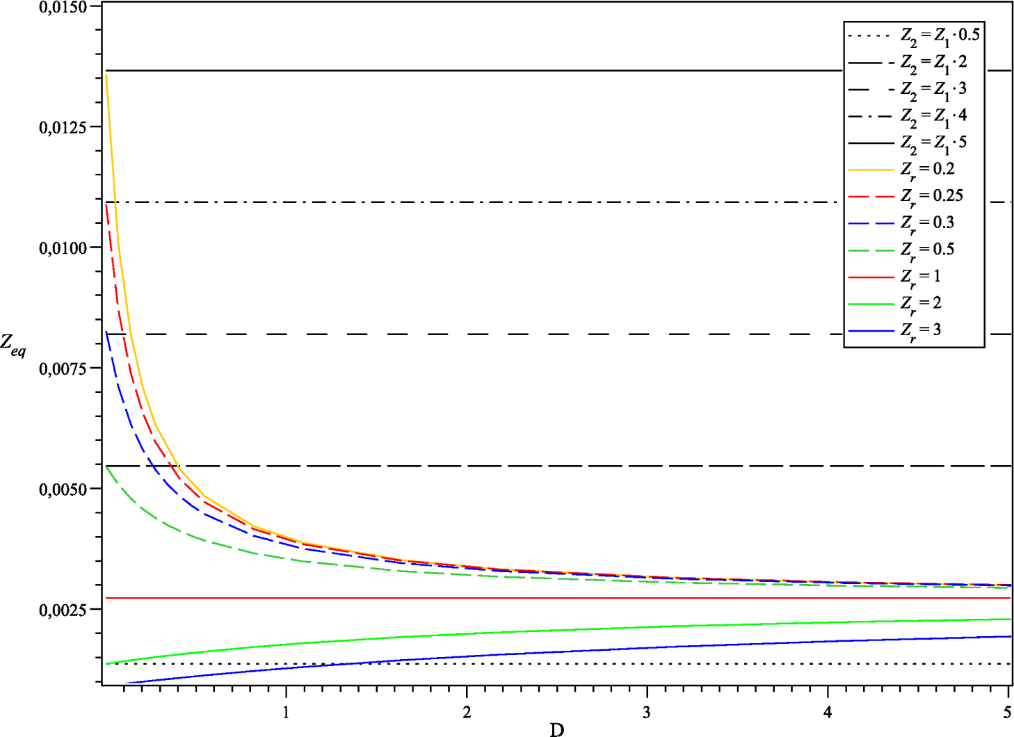
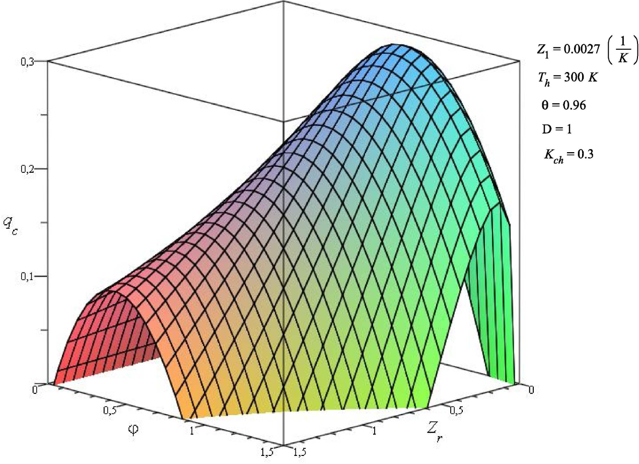
4.4. Role of the Equivalent Figure of Merit

In the previous section, we studied the effect of the external conductance matching on the performance and the cooling capacity of our system. In this section, we analyze the role of the equivalent figure of merit, Zeq, in the qc and COP parameters in terms of the number of pairs, n and m, and the figure of merit of each component TEM, Z1 and Z2.
Using Equation (23) or Equation (27) and the numerical values of the thermoelectric properties of TEM 2, shown in Table 3, for a fixed value of Z1 = 0.0027, we obtain Figure 10, which shows the equivalent figure of merit of the system as a function of the number pairs of each TEM.
Our results show that if the thermoelectric properties of both modules have the same value, Zr = 1, the equivalent figure of merit Zeq becomes independent of the number of pairs. On the other hand, if Zr ≠ 1, the equivalent figure of merit approaches Zr = 1, as the number of pairs increases. Meanwhile, if the number of pairs ratio decreases, the value of Zeq tends to the figure of merit that satisfies the Zr. Notice that the value of Zeq is not greater that the values of the figure of merit for each TEM of the system, independently of the number, n or m, of the number of pairs. Thus, the result is according to the theorem of Bergman [17], which says that the equivalent figure of merit of the TEM, can only be lower than the highest Z of the more efficient TEM. The value of Zeq is affected by the figure of merit ratio Zr. When Zr is lower than the unit, or Z2 > Z1, it is possible to increase the values of the equivalent figure of merit by having a lower number of pairs ratio n > m, but it is not possible to get a higher value than the Z2 that satisfies the Zr. Our analysis is consistent with the obtained results for thermoelectric generator systems [8] because of the generality of Bergman Theorem.

4.5. Simplified Approaches: Previously Considered Cases

Finally, in this section, we derive some results previously obtained for more simple models. From Equation (18), by setting qc = 0, it is possible to get the full solution for the temperature ratio θ,
θ = 1 φ ( 1 φ ρ ) 1 2 φ 2 1 φ ρ + 2 ρ Z e q T c + 1
In order to proceed with the approaches, it is necessary to define a new temperature ratio θh:
θ h = 1 θ = φ ( 1 φ ρ ) 1 2 φ 2 1 φ ρ + 2 ρ Z e q T c + 1 .
Now, solving d θ h d φ = 0, φmax can be approximated through a power series expansion, leading to:
φ max = Z e q T c ( 1 2 Z 2 T c 2 + 2 Z e q T c ) ρ + O ( ρ 2 )
and finally, substituting φmax into Equation (34) yields:
θ h ( max ) = φ max ( 1 φ max ρ ) 1 2 φ max 2 ( 1 φ max ρ + 2 ρ ) Z e q T c + 1
In the limit ρ → 0 or when Kc >> (mK1 + nK2), the maximum dimensionless current and temperature ratio are respectively reduced to:
φ max = Z e q T c
θ h ( max ) = 1 2 Z e q T c + 1
We highlight the fact that if the thermoelectric properties of the two modules are the same, i.e., α1 = α2 = α, R1 = R2 = R and K1 = K2 = K, then the equivalent figure of merit becomes the ordinary one, and from Equations (37) and (38) we obtain,
φ max = Z T c
θ h ( max ) = 1 2 Z T c + 1
Equations (39) and (40) have been previously obtained by many authors [5,6].

5. Conclusions

Using our proposed approach to analyze a composite TEC system, formed by two TEMs, with different thermoelectric properties each, connected thermally in parallel and electrically in series, equivalent thermoelectric properties have been derived. These equivalent properties depend on all thermoelectric parameters of the composite TEC system, namely Seebeck coefficients, α(1,2), thermal conductivity, K(1,2), the electrical resistance, R(1,2), of each TEM and external thermal conductances K(c,h). The corresponding dimensionless heat balance equations may be very useful for the design of composite thermoelectric systems, because they show the relation of the thermoelectric parameters of the TEM components of the system. The main parameters of the TEC system are external thermal conductances of heat exchangers, Kch, and the figures of merit ratio, Zr. The obtained results from this approach show the effect of two or more thermoelectric parameters on the COP and qc of the system. In this work, it is shown that the maximum values for COP and qc are determined by the external thermal conductances ratio Kch, with the condition Kc < Kh. In general, we have shown (see Section 4) that our approach permits us to determine the optimal values of qc and COP for different working conditions determined. The obtained results in this work are useful for designing composite TEC systems with thermal coupling, Kch. We show the consistency of our approach obtaining the COP as a function of the input voltage for a commercial thermoelectric module connected electrically in series. Furthermore, we have derived results previously obtained by many authors as limit cases of our approach. Finally, we point out that the proposed approach in this work can be easily extended to include many TEMs with different thermoelectric properties, each one connected thermally in parallel and electrically in series.

Acknowledgments

M.A.O.R. This work was financially supported by research grant 20150488 of Instituto Politecnico Nacional, Mexico. C.Y.F.N. was partially financially supported by CONACyT, Mexico (grant no. 514381). The authors acknowledge the editorial assistance of the editors to improve the manuscript.

A. Effect of the Thermoelectric Parameters in COP and Qc

In this Appendix, we list figures showing the effect of the thermoelectric parameters on COP and qc of the system. Notice that several results are included in the 3D figures discussed in the above sections. The figures in this Appendix show important limit intervals of the thermoelectric parameters.

A.1. Cooling Capacity qc

We reproduce several results for qc in terms of thermal conductances, Kc and Kh, electrical current, φ, and the figure of merit, Z.
Figure 11 shows the effect of the external conductances, Kch = Kc/Kh, on the cooling capacity qc. At the same electrical current φ, we can obtain different maximum values for qc for a given value of Zr = Z1/Z2.
On the other hand, for a given Kch, the behavior of cooling capacity qc vs. the electrical current is shown in Figure 12 when we change the figures of merit ratio Zr.

A.2. Coefficient of Performance

In this Appendix section, we obtain several results for COP in terms of thermal conductance, Kch, electrical current, φ, and figure of merit, Z, see Figures 1315. Our results contained in the Appendix show important intervals of limit values for the thermoelectric parameters. For example, as Zr increases in the TEMs, clearly, for the same current, we have different cooling capacities. In Figure 12, we show that there are intervals for φ in which qc is zero for a given Zr value. If Z of any TEM increases, qc increases also. Figure 4 shows some intervals for maximum values of qc for this condition.

Author Contributions

M.A.O.R. designed research; C.Y.F.N. calculated the data; M.A.O.R. and C.Y.F.N. analyzed data; I.L. supervised the dimensionless analysis, read and commented on the manuscript; M.A.O.R. and C.Y.F.N. wrote the paper. All authors have read and approved the final manuscript.

Conflicts of Interest

The authors declare no conflicts of interest.

Nomenclature

COP
Coefficient of performance
D
Number of pair ratio
I
Electric current through thermoelements  (A)
K
Thermal conductance of thermoelement
Kc
Thermal conductance of cold-end heat exchanger   ( W K )
Kch
Thermal conductance of heat exchangers ratio
Kh
Thermal conductance of hot-end heat exchanger   ( W K )
m
Total number of thermoelements at first TEM
n
Total number of thermoelements at second TEM
qc
Dimensionless cooling capacity
qh
Dimensionless heat rejection
Qc
Cooling capacity of the TEC system  (W)
Qh
Heat rejection of the TEC system  (W)
R
Electric resistance of thermoelement  ()
T1
Hot end temperature of TEMs  (K)
T2
Cold end temperature of TEMs  (K)
Tc
Temperature of the cold reservoir  (K)
Th
Temperature of the hot reservoir  (K)
V
Input voltage  (V)
Z
Figure of merit   ( 1 K )
Zr
Figures of merit ratio
Zeq
Equivalent figure of merit
Greek Letters
α
Seebeck coefficient of thermoelement   ( V K )
δ
Cold conductance ratio
T
Temperature across the TEMs  (K)
ρ
Hot conductance ratio
θ
Temperature of heat reservoirs ratio
φ
Dimensionless current
µ
Coupling factor
Subscripts
1
First TEM
2
Second TEM
eqH
Equivalent for hot side
eqC
Equivalent for cold side
ch
Heat exchangers conductances ratio
Lou
Thermoelectric value obtained through Z. Luo’s method
r
Ratio
max
Maximum

References

  1. Rowe, D.M. Thermoelectric Handbook, Macro to Nano; CRC Press: Taylor and Francis Group, Boca Raton, FL, USA, 2006. [Google Scholar]
  2. Nolas, G.S.; Sharp, J.; Goldsmid, H.J. Thermoelectrics: Basic Principles and New Materials Developments; Springer Verlag: Berlin, Germany, 2001. [Google Scholar]
  3. Shakouri, A. Recent Development in Semiconductor Thermoelectric Physics and Materials. Ann. Rev. Mater. Res. 2011, 41, 399–431. [Google Scholar]
  4. Riffat, S.B.; Ma, X. Thermoelectrics: A Review of Present and Potential Applications. Appl. Therm. Eng. 2003, 23, 913–935. [Google Scholar]
  5. Yamanashi, M. A New Approach to Optimum Design in Thermoelectric Cooling Systems. J. Appl. Phys. 1996, 80, 5494–5502. [Google Scholar]
  6. Xuan, X.C. Investigation of Thermal Contact Effect on Thermoelectric Coolers. Energ. Convers. Manage. 2003, 44, 399–410. [Google Scholar]
  7. Pearson, M.R.; Lents, C.E. Dimensionless Optimization of Thermoelectric Cooler Performance when Integrated within a Thermal Resistance Network. Proceedings of the ASME 2013, International Mechanical Engineering Congress and Exposition, San Diego, CA, USA, 15–21 November 2013; pp. V010T11A087–V010T11A087.
  8. Apertet, Y.; Ouerdane, H.; Goupil, C.; Lecoeur, P. Thermoelectric Internal Loops inside Inhomogeneous System. Phys. Rev. B 2012, 85, 033201. [Google Scholar]
  9. Apertet, Y.; Ouerdane, H.; Glavatskaya, O.; Goupil, C.; Lecoeur, P. Optimal Working Conditions for Thermoelectric Gnerators with Realistic Thermal Coupling. Europhys. Lett. 2012, 97, 28001. [Google Scholar]
  10. Vargas-Almeida, A.; Olivares-Robles, M.A.; Camacho-Medina, P. Thermoelectric System in Different Thermal and Electrical Configurations: Its Impact in the Figure of Merit. Entropy 2013, 15, 2162–2180. [Google Scholar]
  11. Camacho-Medina, P.; Olivares-Robles, M.A.; Vargas-Almeida, A. Maximum Power of Thermally and Electrically Coupled Thermoelectric Generators. Entropy 2014, 16, 2890–2903. [Google Scholar]
  12. Ioffe, A. Semiconductor Thermoelements and Thermoelectric Cooling; Infosearch: London, UK, 1957. [Google Scholar]
  13. Home page of TE Technology. Available online: http://tetech.com accessed on 1 February 2015.
  14. Home page of Thermal Force. Available online: http://thermalforce.de accessed on 1 June 2015.
  15. Luo, Z. A Simple Method to Estimate the Physical Characteristics of a Thermoelectric Cooler from Vendo Datasheet. Electon. Cool. 2008, 14, 22–27. [Google Scholar]
  16. Series-Parallel Modules. Available online: https://tetech.com/Peltier-thermoelectric-cooler-modules/series-parallel/ accessed on 5 June 2015.
  17. Bergman, D.J.; Levy, O. Thermoelectric Properties of a Composite Medium. J. Appl. Phys. 1991, 70, 6821–6833. [Google Scholar]
Figure 1. Schematic of a Dual Thermoelectric Cooling System.
Entropy 17 03787f1
Figure 2. Cooling capacity vs. the external conductance ratio with different dimensionless currents.
Entropy 17 03787f2
Figure 3. Cooling capacity vs. the external conductance ratio with different figure of merit ratios and dimensionless current.
Entropy 17 03787f3
Figure 4. Cooling capacity vs. the figure of merit ratio with different dimensionless current.
Entropy 17 03787f4
Figure 5. Cooling capacity vs. the figure of merit ratio and dimensionless current.
Entropy 17 03787f5
Figure 6. COP vs. the external conductance ratio with different dimensionless currents.
Entropy 17 03787f6
Figure 7. COP vs. the external conductances ratio with different figures of merit and dimensionless current.
Entropy 17 03787f7
Figure 8. COP vs. the figure of merit ratio and dimensionless current.
Entropy 17 03787f8
Figure 9. COP vs. the input voltage corresponding to an SP − 254 − 1.0 − 2.5 (series) TEC module connected in series.
Entropy 17 03787f9
Figure 10. Equivalent figure of merit vs. the number of pairs ratio with different figure of merit ratios.
Entropy 17 03787f10
Figure 11. Cooling capacity vs. dimensionless current with different external thermal conductances ratios.
Entropy 17 03787f11
Figure 12. Cooling capacity vs. dimensionless current with different figure of merit ratios.
Entropy 17 03787f12
Figure 13. COP vs. dimensionless current with different external conductances ratios.
Entropy 17 03787f13
Figure 14. COP vs. dimensionless current with different figure of merit ratios.
Entropy 17 03787f14
Figure 15. COP vs. the figure of merit ratio with different dimensionless currents.
Entropy 17 03787f15
Table 1. COP for different values Kch.
KchCOPCOP
01.98660.045
0.051.94160.0437
0.101.89790.0424
0.151.85550.0412
0.201.81430.0400
0.251.77430.0389
0.301.73540.0378
0.351.69760.0368
0.401.66080.0358
0.451.62500.0349
0.501.59010.0339
0.551.55620.0331
0.601.52310.0322
0.651.49090.0314
0.701.45950.0306
0.751.42890.0298
0.801.39910.0292
0.851.36990.0284
0.901.34150.0278
0.951.31370.0271
Table 2. Values of ρ and δ for given values of Kch.
Kch0.30.512
δ0.35220.35220.35220.3522
ρ0.105660.17610.35220.7044
Table 3. Numerical values of the thermoelectric properties of TEM 2 when Z1 = 0.0027.
Zrα2R2K2Z2
0.10.01700.3410.03130.0273
0.50.03811.7050.15650.0054
10.0543.410.3130.0027
20.07666.820.6260.0013
30.093510.230.9390.0009

