
Thermodynamics Analysis of Variable Viscosity Hydromagnetic Couette Flow in a Rotating System with Hall Effects

Abstract
:
1. Introduction
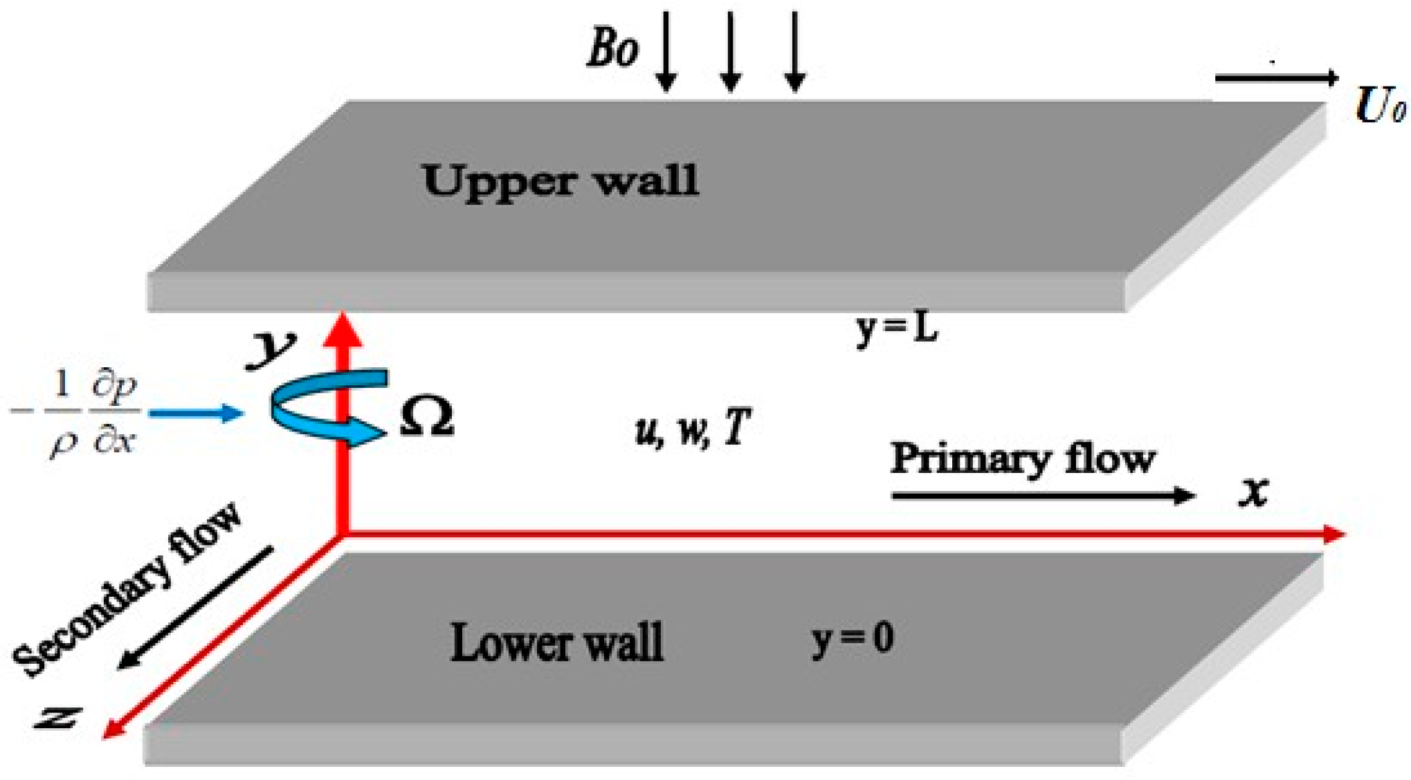
2. Mathematical Analysis
3. Numerical Procedure
4. Results and Discussion


5. Conclusions
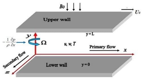
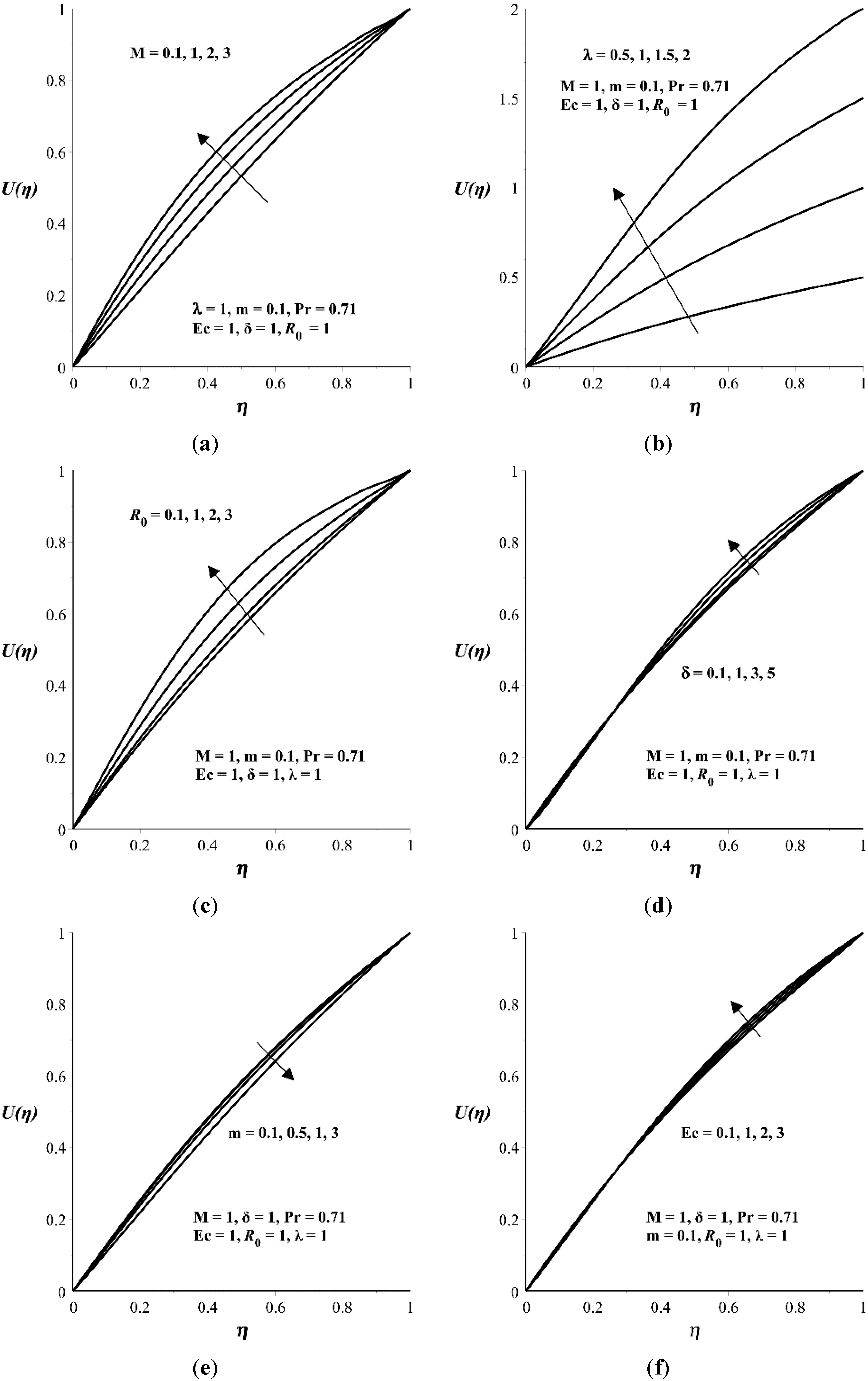
- The primary velocity profiles in x-direction increases with M, , , and δ but decreases with m.
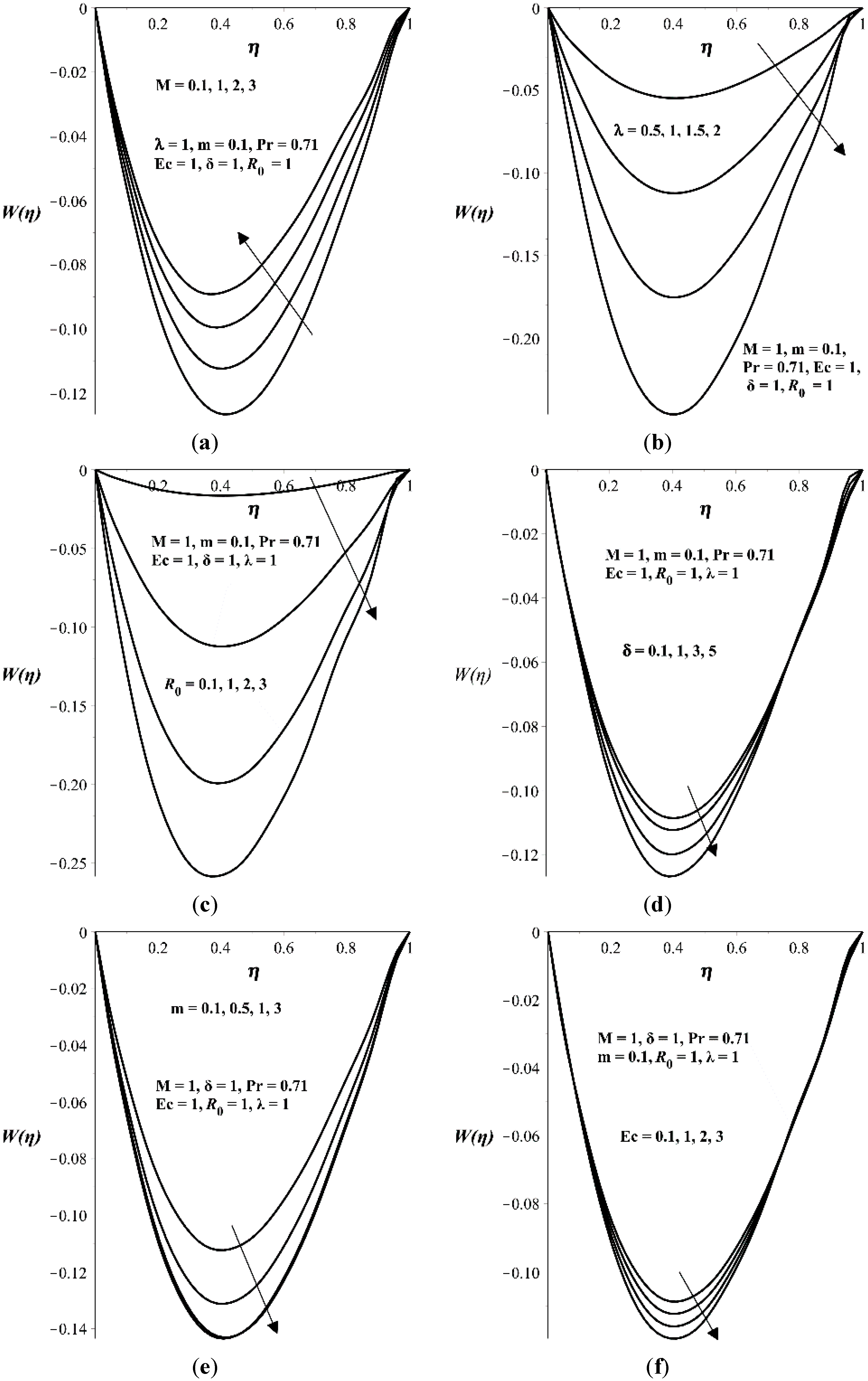
- The secondary velocity profiles in z-direction increases with M but decreases with , , δ and m.
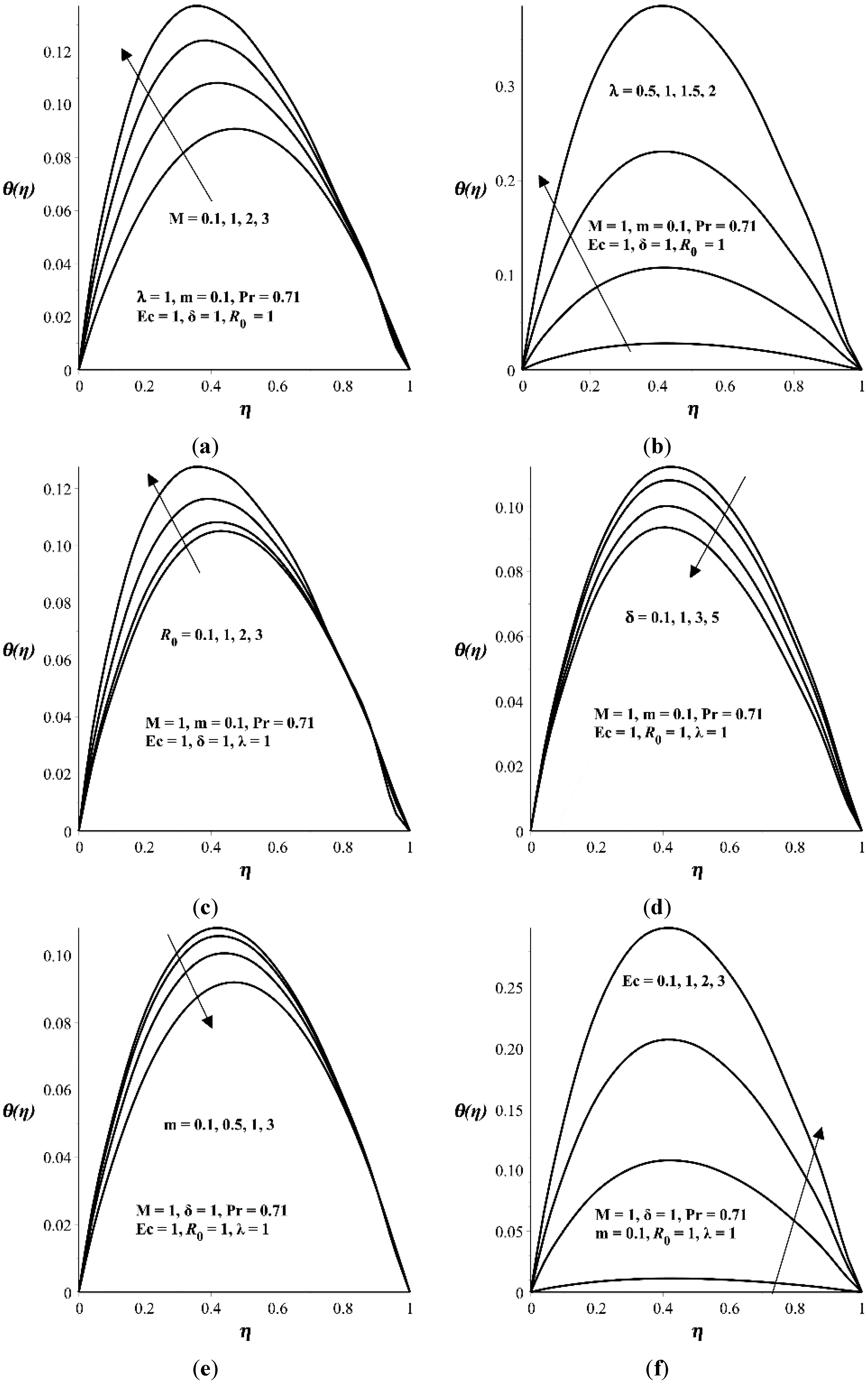
- The temperature profile increases with M, , , and Ec but decreases with m and δ.
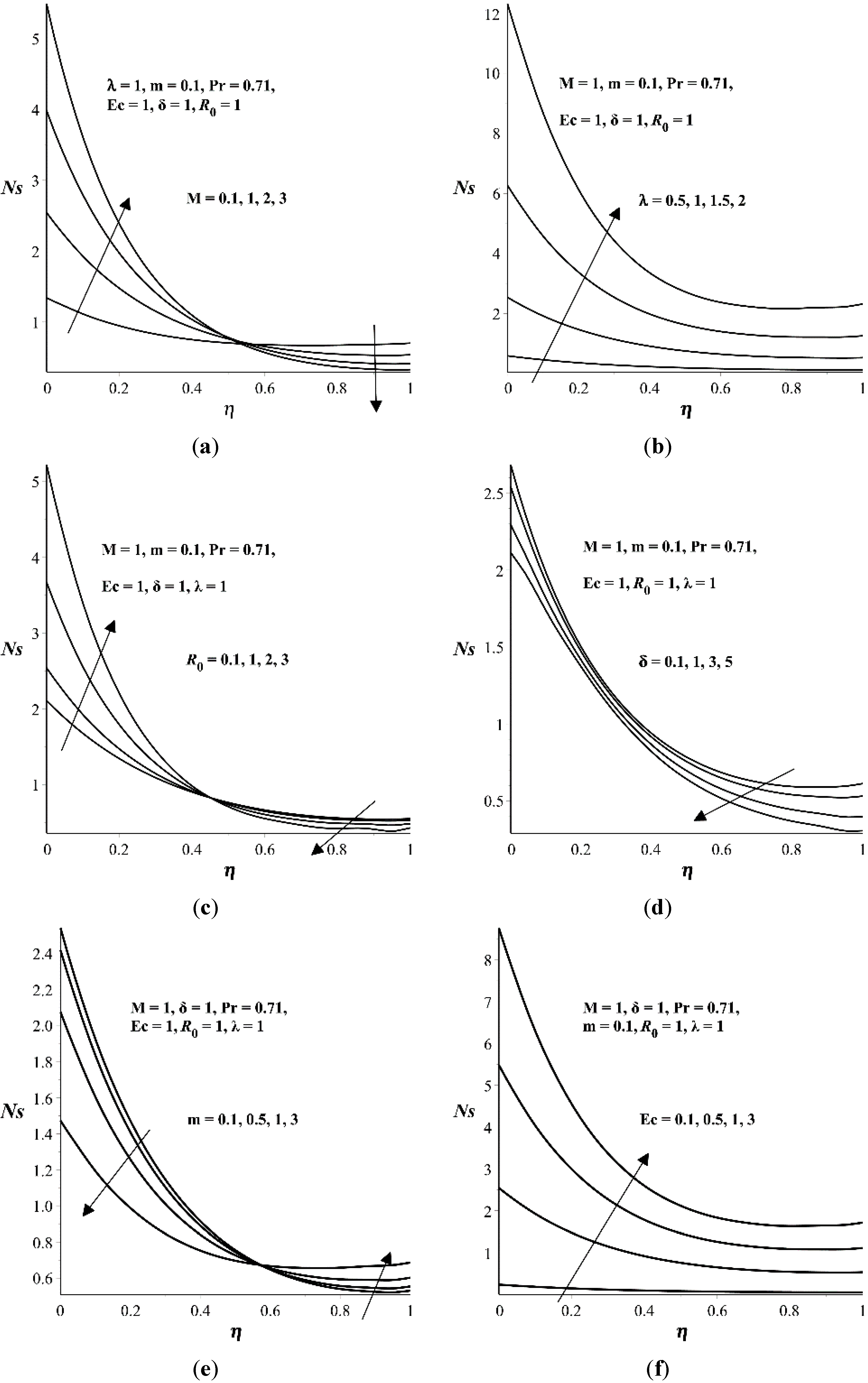
- The entropy generation rate increases with and Ec but decreases with δ.
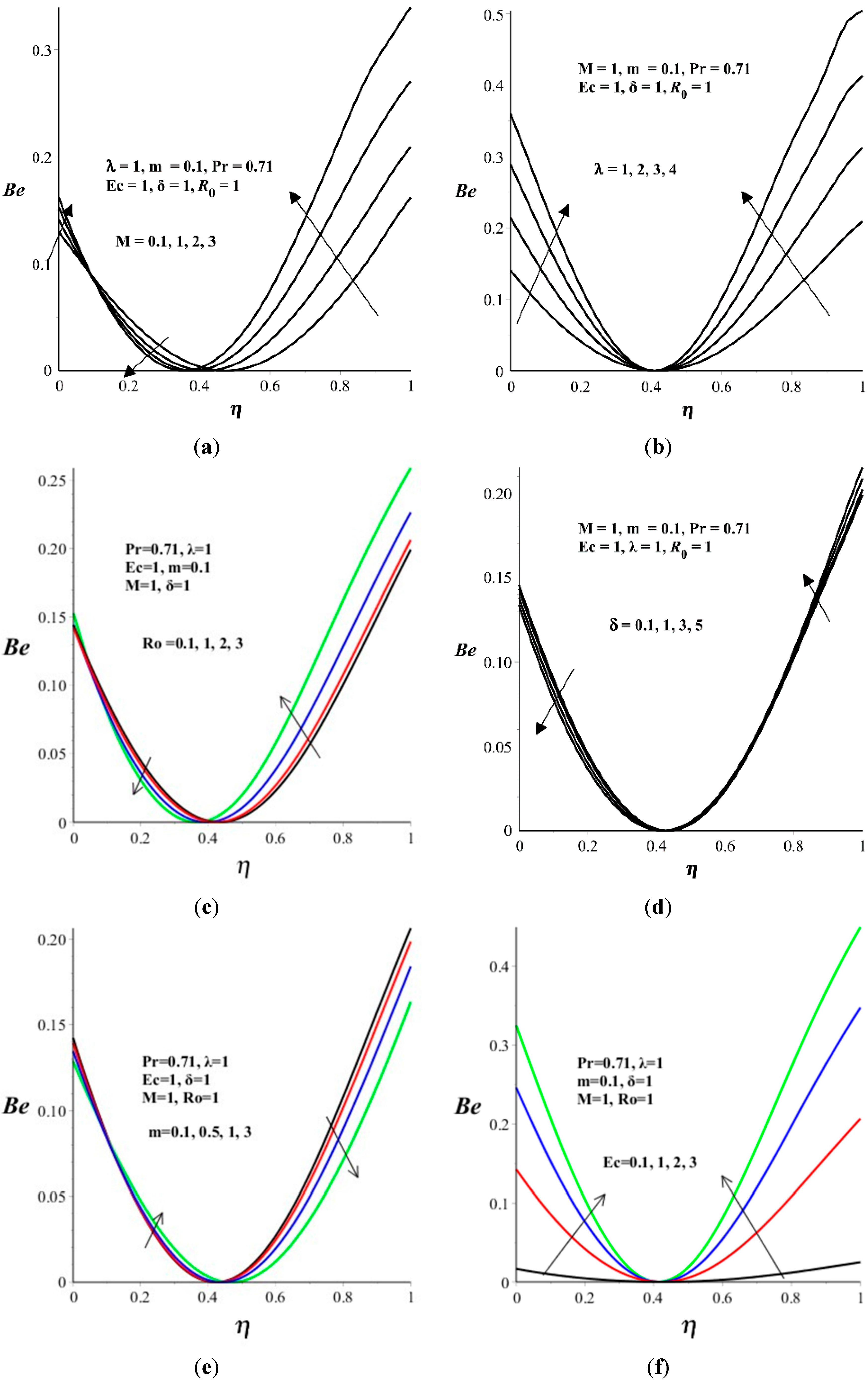
- Heat transfer irreversibility is more at the upper moving wall as compared to lower fixed wall. A point exists at η = 0.4 where the fluid friction and magnetic field irreversibility completely dominate the flow system. The Bejan number increases with λ and Ec.
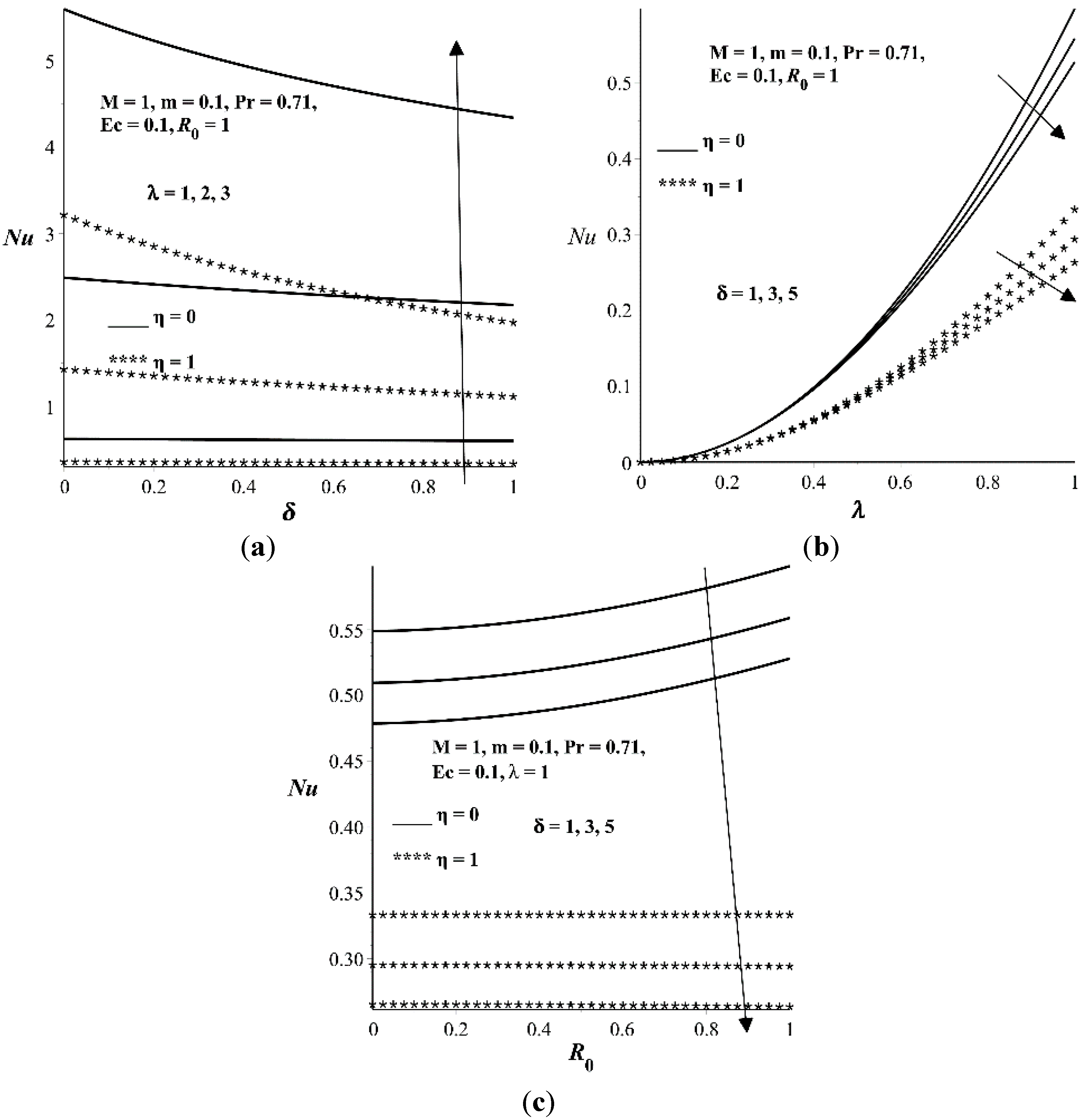
- The Nusselt number is higher at the lower wall as compared to upper wall. An increase in λ and increases Nu while an increase in δ decreases Nu.
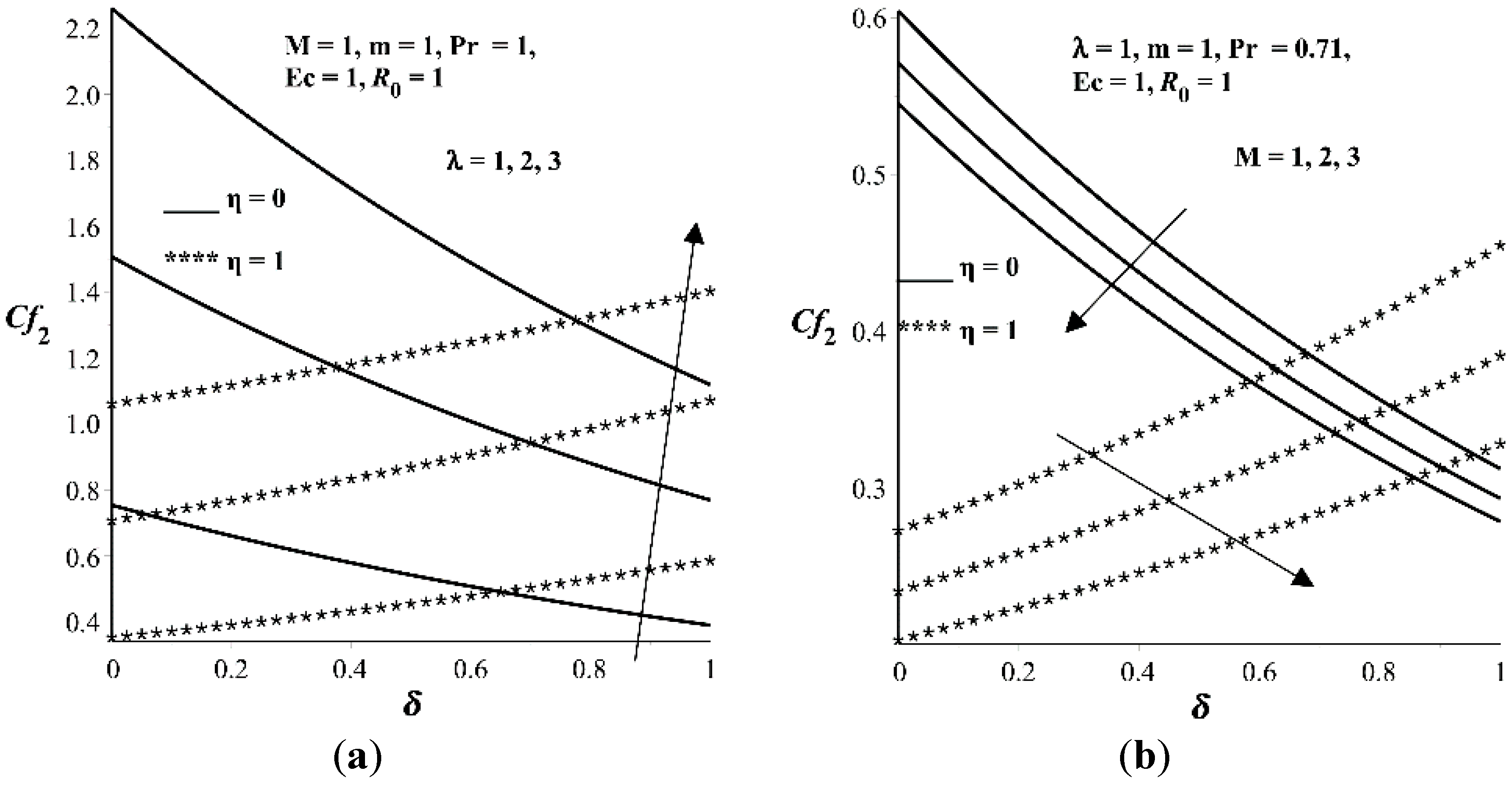
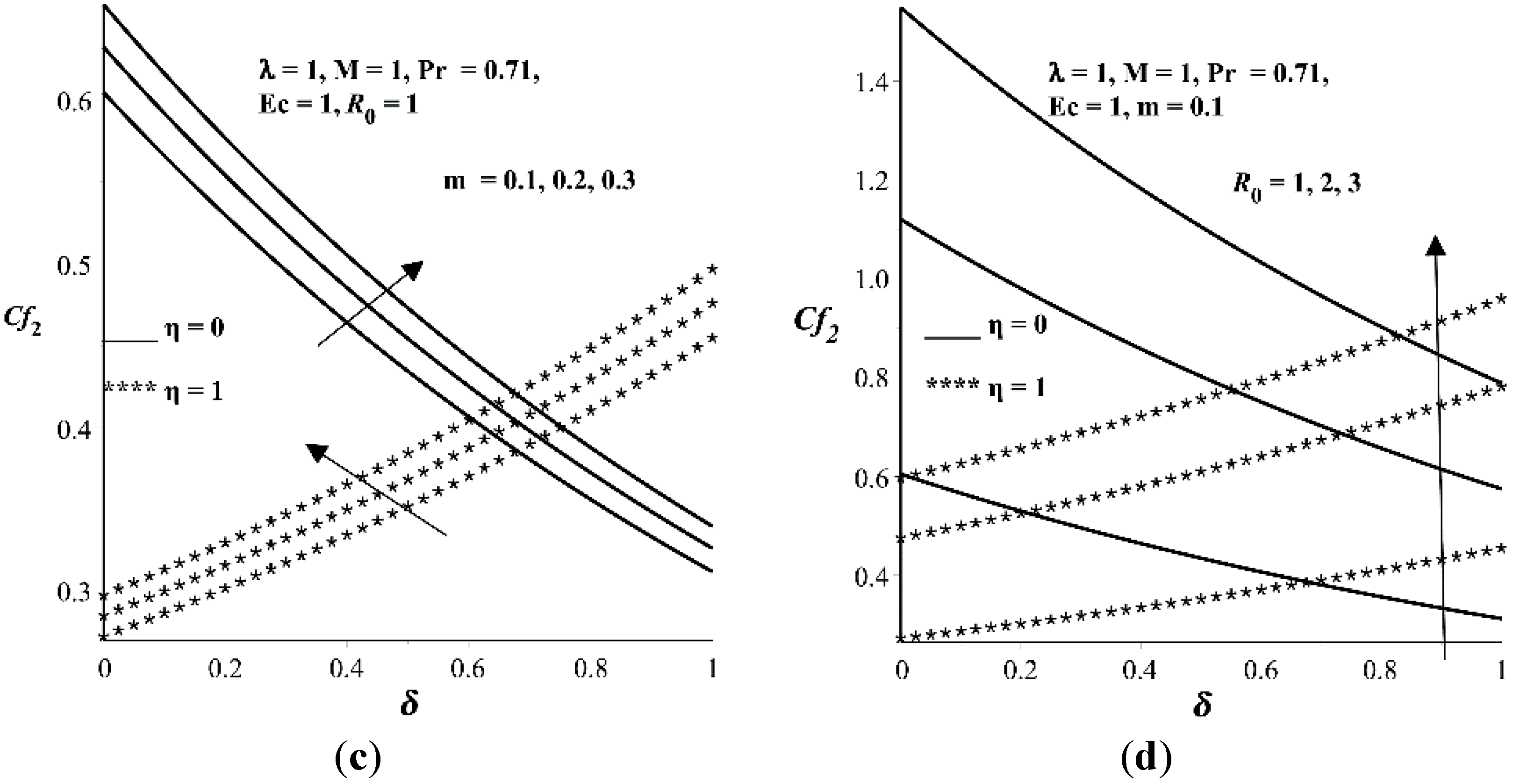
- The secondary flow skin friction coefficient increases with λ, m, and but decreases with M.
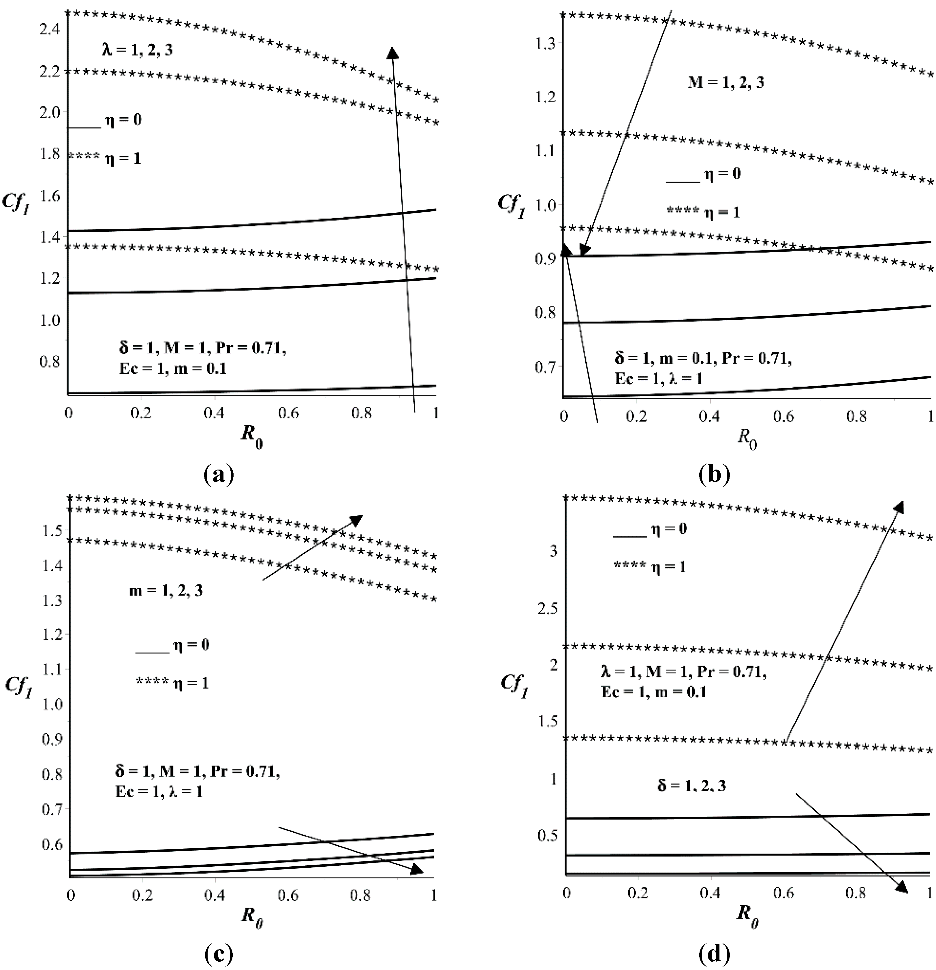
- Increase in and M increases the primary flow skin friction coefficient at the lower wall but decreases it at the upper wall. The trend is opposite with increasing parameter values of m and δ. An increase in λ increases the primary flow skin friction at both lower and upper walls.
Acknowledgments
Author Contributions
Conflicts of Interest
References
- Barikbin, Z.; Ellahi, R.; Abbasbandy, S. The Ritz–Galerkin method for MHD Couette flow of non-Newtonian fluid. Int. J. Ind. Math. 2014, 6, 235–243. [Google Scholar]
- Khan, A.A.; Ellahi, R.; Usman, M. The effects of variable viscosity on the flow of non-Newtonian fluid through a porous medium in an inclined channel with slip conditions. J. Porous Media 2013, 16, 59–67. [Google Scholar] [CrossRef]
- Rashad, A.M. Effects of radiation and variable viscosity on unsteady MHD flow of a rotating fluid from stretching surface in porous medium. J. Egypt. Math. Soc. 2014, 22, 134–142. [Google Scholar] [CrossRef]
- Torabi, M.; Zhang, K. First and second thermodynamic laws analyses between and inside two rotating solid cylindrical geometries with magnetohydrodynamic flow. Int. J. Heat Mass Transf. 2015, 89, 760–769. [Google Scholar] [CrossRef]
- Hayat, T.; Nadeem, S.; Siddiqui, A.M.; Asqhar, S. An oscillating hydromagnetic non-Newtonian flow in a rotating system. Appl. Math. Lett. 2004, 17, 609–614. [Google Scholar] [CrossRef]
- Eegunjobi, A.S.; Makinde, O.D. Second law analysis for MHD permeable channel flow with variable electrical conductivity and asymmetric Navier slips. Open Phys. 2015, 13, 100–110. [Google Scholar] [CrossRef]
- Attia, H.A. Effect of Hall current on transient hydromagnetic Couette–Poiseuille flow of a viscoelastic fluid with heat transfer. Appl. Math. Model. 2008, 32, 375–388. [Google Scholar] [CrossRef]
- Makinde, O.D.; Chinyoka, T. Numerical study of unsteady hydromagnetic Generalized Couette flow of a reactive third-grade fluid with asymmetric convective cooling. Comput. Math. Appl. 2011, 61, 1167–1179. [Google Scholar] [CrossRef]
- Eegunjobi, A.S.; Makinde, O.D. Entropy Generation Analysis in a Variable Viscosity MHD Channel Flow with Permeable Walls and Convective Heating. Math. Probl. Eng. 2013, 2013. [Google Scholar] [CrossRef]
- Shivakumara, I.S.; Lee, J.; Vajravelu, K.; Akkanagamma, M. Electrothermal convection in a rotating dielectric fluid layer: Effect of velocity and temperature boundary conditions. Int. J. Heat Mass Transf. 2012, 55, 2984–2991. [Google Scholar] [CrossRef]
- Nadeem, S.; Saleem, S. Analytical study of third grade fluid over a rotating vertical cone in the presence of nanoparticles. Int. J. Heat Mass Transf. 2015, 85, 1041–1048. [Google Scholar] [CrossRef]
- Turkyilmazoglu, M. Exact solutions for the incompressible viscous magnetohydrodynamic fluid of a porous rotating disk flow with Hall current. Int. J. Mech. Sci. 2012, 56, 86–95. [Google Scholar] [CrossRef]
- Zakinyan, A.; Nechaeva, O.; Dikansky, Y. Motion of a deformable drop of magnetic fluid on a solid surface in a rotating magnetic field. Exp. Therm. Fluid Sci. 2012, 39, 265–268. [Google Scholar] [CrossRef]
- Feiz-Dizaji, A.; Salimpour, M.R.; Jam, F. Flow field of a third-grade non-Newtonian fluid in the annulus of rotating concentric cylinders in the presence of magnetic field. J. Math. Anal. Appl. 2008, 337, 632–645. [Google Scholar] [CrossRef]
- Hayat, T.; Khan, L.A.; Ellahi, R.; Obaidat, S. Exact solutions on MHD flow past an accelerated porous plate in a rotating frame. Chin. Phys. Lett. 2011, 28. [Google Scholar] [CrossRef]
- Batista, M. Steady flow of incompressible fluid between two co-rotating disks. Appl. Math. Model. 2011, 35, 5225–5233. [Google Scholar] [CrossRef]
- Singh, A.K.; Singh, N.P.; Singh, U.; Singh, H. Convective flow past an accelerated porous plate in rotating system in presence of magnetic field. Int. J. Heat Mass Transf. 2009, 52, 3390–3395. [Google Scholar] [CrossRef]
- Malashetty, M.S.; Swamy, M.S.; Sidram, W. Thermal convection in a rotating viscoelastic fluid saturated porous layer. Int. J. Heat Mass Transf. 2010, 53, 5747–5756. [Google Scholar] [CrossRef]
© 2015 by the authors; licensee MDPI, Basel, Switzerland. This article is an open access article distributed under the terms and conditions of the Creative Commons Attribution license (http://creativecommons.org/licenses/by/4.0/).
Share and Cite
Makinde, O.D.; Eegunjobi, A.S.; Tshehla, M.S. Thermodynamics Analysis of Variable Viscosity Hydromagnetic Couette Flow in a Rotating System with Hall Effects. Entropy 2015, 17, 7811-7826. https://doi.org/10.3390/e17117811
Makinde OD, Eegunjobi AS, Tshehla MS. Thermodynamics Analysis of Variable Viscosity Hydromagnetic Couette Flow in a Rotating System with Hall Effects. Entropy. 2015; 17(11):7811-7826. https://doi.org/10.3390/e17117811
Chicago/Turabian StyleMakinde, Oluwole D., Adetayo S. Eegunjobi, and M. Samuel Tshehla. 2015. "Thermodynamics Analysis of Variable Viscosity Hydromagnetic Couette Flow in a Rotating System with Hall Effects" Entropy 17, no. 11: 7811-7826. https://doi.org/10.3390/e17117811