All articles published by MDPI are made immediately available worldwide under an open access license. No special
permission is required to reuse all or part of the article published by MDPI, including figures and tables. For
articles published under an open access Creative Common CC BY license, any part of the article may be reused without
permission provided that the original article is clearly cited. For more information, please refer to
https://www.mdpi.com/openaccess.
Feature papers represent the most advanced research with significant potential for high impact in the field. A Feature
Paper should be a substantial original Article that involves several techniques or approaches, provides an outlook for
future research directions and describes possible research applications.
Feature papers are submitted upon individual invitation or recommendation by the scientific editors and must receive
positive feedback from the reviewers.
Editor’s Choice articles are based on recommendations by the scientific editors of MDPI journals from around the world.
Editors select a small number of articles recently published in the journal that they believe will be particularly
interesting to readers, or important in the respective research area. The aim is to provide a snapshot of some of the
most exciting work published in the various research areas of the journal.
The rotated quasi-orthogonal space-time block code (RQSTBC) for asynchronous cooperative diversity is proposed in this paper. The source selects half of the symbols from a signal constellation set and the other half of them from that constellation rotated with the optimum angle. Meanwhile, it constructs orthogonal frequency division multiplexing (OFDM) frames to counterbalance time delays of the signals. Then, relays create the frequency domain quasi-orthogonal space-time block transmitted signals matrix in such a way that its items are staggered to take on the Jafarkhani code structure or time-reversion of it. These three stages let the received signals at the destination take on RQSTBC structure with diversity order 4, which results in the fast symbol-pair-wise maximum likelihood (ML) decoder. Simulation results have shown that the proposed scheme outperforms the other asynchronous cooperative diversity schemes considered in this paper.
Though multiple transmit antennas and receiver antennas at nodes would lead to substantial gains in channel capacity and robust abilities to combat with different kinds of interference over a scattering-rich wireless environment, constrained by the space complexities, it is impractical for nodes in ad hoc networks or distributed large scale wireless networks [1]. Meanwhile, the communication between the nodes accomplished by a single hop is severely affected by fading, path loss, etc. If the nodes between the source and the destination are regarded as the relay nodes that participate in the transmission, a virtual multi-antenna system, referred to as cooperative diversity, could be built, which leads the wireless ad hoc networks [1] being indispensable to the next generation broadband radio access networks [2].
The efficiency of the cooperative diversity for wireless ad hoc networks [1,2] would be evaluated by three aspects: (i) whether it achieves full diversity; (ii) whether it transmits symbols with maximum rate; and (iii) whether the receiver could exploit the decoder with both good performance and a lower complexity [1,3].
However, synchronization is essential to most of relevant researches on cooperative diversity, which violates the principle that the cooperative diversity is asynchronous since each relay is furnished with different antennas, each terminal of which operates in its own local working frequency. This in turn lets asynchronous cooperative diversity [4], an open research topic to deal with this problem, be attracted the most attention.
Taking into account asynchronous characteristic of different mobile nodes, almost all of the distributed space time codes can achieve full diversity [5,6,7]. However, a few of them give attention to three all. Among them is the Alamouti space time transmission scheme (ASTTS) [7] that stems from the ideas of orthogonal frequency division multiplexing (OFDM), time-reversion and complex conjugation. Nevertheless, confined to Alamouti code structure, its diversity order is 2. Previously, based on the quasi-orthogonal code structure in the Jafarkhani scheme [8], etc., a rotated quasi-orthogonal space time block code (RQSTBC) [3] that provides both full diversity and maximum rate was proposed for four transmit antennas. In this paper, based on the ideas in [3,7,8], we present a RQSTBC asynchronous cooperative scheme, diversity order of which is 4. In contrast to the original one in [7], our novel contribution constructs the frequency domain transmitted signals of the relay nodes in terms of combining the quasi-orthogonal criterion originally proposed in [8] with time-reversion in [7]. The application of this idea lets the received signals at the destination turn on Jafarkhani code [8] structure and thus guarantees both the maximum symbol transmission rate being 1 and fast symbol-pair-wise ML decoder being used. Moreover, the source not only picks half of the symbols from a signal constellation set and the other half of them from that constellation which is rotated with the optimum angle and but also creates OFDM frames to make up for time delays of the signals. In this way, the received signals at the destination take on RQSTBC with the Jafarkhani code structure. It is this step that the proposed scheme can ensure full diversity.
Theoretical analysis and simulation results show that the performance of the proposed scheme is superior to those of QSTBC scheme and ASTTS scheme. This is attributed to the higher diversity order of the new scheme.
Throughout this paper we adopt the following notational conventions. Boldface capitals and lower-case letters symbolize matrices and vectors, respectively, while ( )T and ( )H represent the transpose and Hermitian transpose, respectively. Furthermore, ζ( ) denotes the time-reversion of the signal, while ( )* expresses the complex conjugation of the signal. Finally, det[ ] is the determinant of a matrix.
2. System Model
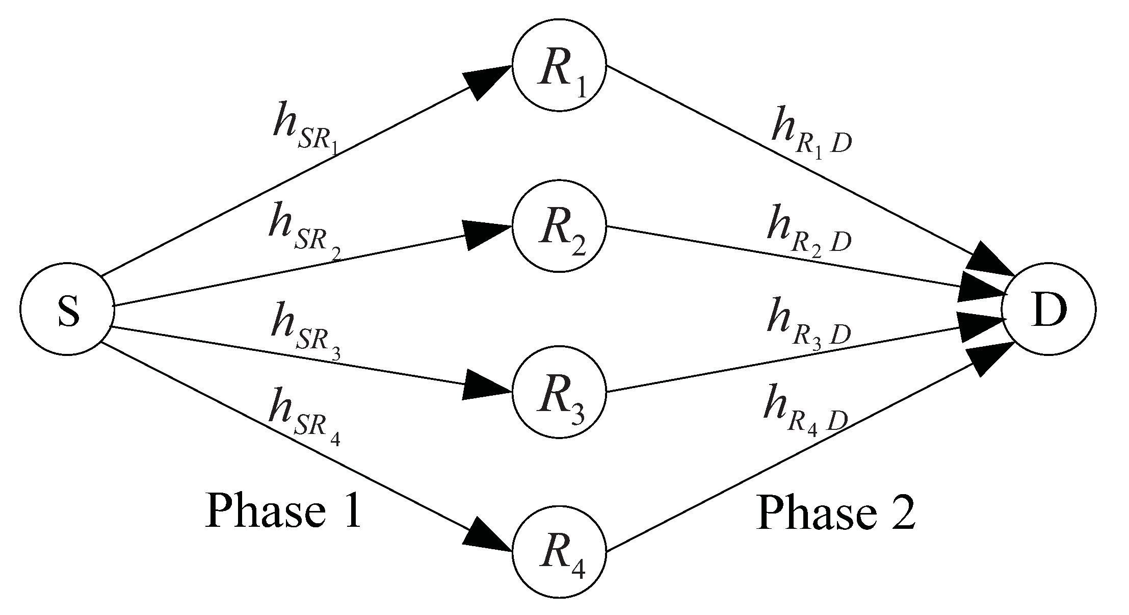
Considering a cooperative communication system with a source S, a number of potential relays Rj (j = 1, …, k, …, M = 2 K (To achieve full diversity and full symbol transmission rate, it is necessary that there are M = 4 relays in a two-hop cooperative communication system. Thus, there are only four relays in this figure.)) and a destination D. Constrained by the transmitted power and the distance, the data to be transmitted from the source node to the destination node have to be with the aid of the relay nodes, the cooperative communication of which are divided into two phases. In Phase I, S broadcasts its information to potential relays, and a destination D. In Phase II, S stops transmission, and potential relays start to transmit. The configuration of a cooperative communication system is depicted in Figure 1.
Figure 1.
The configuration of a cooperative communication system.
Figure 1.
The configuration of a cooperative communication system.
In this figure, each node is equipped with a single half duplex radio and a single antenna, while and denote the channel coefficients which link the source node to the jth relay node and the jth relay node to the destination node, respectively.
When all nodes work in an asynchronous cooperative communication mode, in a given time interval, D(t), the equivalent received signal is the superposition of the signals, obtained from a mapping from the M relays transmitted signals to the destination terminal, together with the white noise as expressed by:
where and are defined above, represents a mapping performed by the jth relay node, S(t) means transmitted symbol from the source node, and δj is the relative time delay of the signals arrived at the destination node from the source node, n(t) is the additive white Gaussian noise (AWGN) stochastic process with zero mean and unit variance at time t.
In order to obtain the most likely information transmitted from the source node, we apply the statistic features of time delay among potential paths of relays. By doing that, the constraint of synchronization is removed, and different kinds of asynchronous cooperative diversity scheme are also acquired.
Though asynchronous cooperative diversity can be achieved by asynchronous cooperative transmission through not only adjusting the transmitted time delays among relay nodes to ensure that the data are sent orthogonal but also enhancing the performance of the relevant receiver, this approach can not guarantee obtain full diversity gain [4]. It is to further devise the distributed space-time coding schemes, based on asynchronous cooperative diversity, with both higher transmission rate and higher diversity gain that serves as a motivation to write this paper.
With recent advances in space-time codes, more and more novelty achievements in this area have been applied to construct asynchronous cooperative diversity schemes to improve the performance of the distributed space-time coding schemes [5,6,7,9].
In [7], a scheme of the orthogonal frequency division multiplexing transmission combined with Alamouti space-time coding is applied to achieve asynchronous cooperative diversity. However, confined by the characteristic of Alamouti space-time coding, it has to use clusters to expand scale while increasing the number of relay nodes, which adds the difficulty of coordination among relay nodes. Meanwhile, the orthogonal complex signals with both full diversity gain and full symbol transmission rate can be designed iff the number of antennas is two. Therefore, the transmission rate of the asynchronous cooperative system, based on orthogonal space-time block codes, is less than one when the number of the cluster nodes increases.
Fortunately, QSTBC can have a given asynchronous cooperative system to transmit with maximum rate at the sacrifice of the orthogonal and part of diversity gain and would lead it to achieve the maximum diversity gain smaller than four with the code rate being one.
Furthermore, if QSTBC is merged with the proper rotation factor in the manner of performing rotation transformation on the modulated data symbols, a new system endowed with higher asynchronous cooperative diversity gain is obtained. By doing that, the simple fast symbol-pair-wise ML decoder can be exploited, which results in the proposed scheme with enhanced performances considered in this paper.
The proposed asynchronous cooperative communication system, based on RQSTBC, not only embeds OFDM but also merges the proper rotation factor into QSTBC. In the first place, the source selects half of the symbols from a signal constellation set and the other half of them from that constellation which is rotated with the optimum angle, which guarantees determinant of the coding gain distance (CGD) not being equal to zero and thus leads the diversity gain of the proposed scheme to approximate the diversity order. Second, the cycle prefix (CP) of the OFDM, performed at the source, is applied to compensate the timing delay of multi-streams (MS), which makes the signals among MS asynchronous cooperative, which is then mapped into frequency domain QSTBC at the relay nodes to ensure the full transmission rate as well as the full diversity. Finally, it implements the fast symbol-wise ML decoder for the global optimum, corresponding to the transmitted data, with the lower complexity. When it is applied to executing multi-hop communication, the working principle of it can be stated as follows.
3.1. Forming Transmitted Signals
Let us consider a cooperative system with one source node, one destination node, and four relay nodes, which communicates in bursts of length a frame over flat fading channels, the configuration of which is depicted in Figure 1. First, the source generates a modulated symbol matrix S = [s1, …, sk, …, s4] with sk = [sk 0, …, sk N−1]T, where N is the length of a sequence of modulated symbols to transmitted during kth interval, independent entries of which are carved in manner of half (k = 1, 2) of them from Z, the concentric rings of complex integers, and the other half (k = 3, 4) of them from eϕZ, which means that Z is rotated with an angle ϕ.
Subsequently, it performs N-point inverse discrete Fourier transform (IDFT) operation on s1s3 and N-point discrete Fourier transform (DFT) operation on s2s4, respectively. Each yielding vector is appended by a cycle prefix (CP), which is composed of the last Ncp symbols of the vector , as a protection interval to form one of 4 OFDM frames , expressed as:
Finally, the OFDM frames are broadcasted to the four relays. Note that here, we assume that the length of a CP is Ncp that is larger than the maximum of the relative time delays of the signals arrived at the destination from the source.
3.2. Mapping OFDM Frames into the Frequency Domain QSTBC
The k th frame equivalent low pass received signal of the jth relay corresponding to the kth OFDM frame is expressed by:
Yj k = hS RjXk + nj k
where Yjk = [Yjk(1),…, Yjk(l),…, Yjk(L)]T, njk = [njk(1),…, njk(l),…, njk(L)]T (1 ≤ j ≤ 4, 1≤ k ≤ 4, L = N + Ncp) is the additive white Gaussian noise (AWGN) sample vector with each item being zero mean and unit variance at the jth relay.
Each of the four frames of the received signal is allocated with the optimum power p (Here, the optimum means that if the source transmits the signals with half the total power P and the relays exploit the other half, the Chernoff bound on the pairwise error probability would be minimized [9]. Then, we assume that the transmitted power of source is P1, while the average transmitted power of each relay is P2 and let P1 = 4P2. Therefore, we have [7,9]). Thereafter, the resulting signals are subtly reordered by the individual relay in such a way that the frequency domain transmitted signals Yj k, its complex conjugation version and its time-reversion version act like QSTBC in a multiple-antenna system, denoted by:
where ζ(Yjk(l)) = Yjk(L − l) (j,k = 1,2,3,4, l = 0,…, L − 1) and Y(L) = Y(0).
3.3. The Fast Symbol-Pair-Wise ML Decoder Searching the Global Optimum Signals
First, the destination strips off the CPs from four OFDM frames. Then, it shifts the last Ncp samples of the N-point vector as the first Ncp samples to reconstruct the signals, which were manipulated by the relays with the time-reversion. Subsequently, the received signals are performed by the N-point DFT operation.
Second, due to the fact that (DFT(s))* = IDFT(s*), (IDFT(s))* = DFT(s*), DFT(ζ (DFT(s))) = s, we can deduce the sufficient statistics with respect to the transmitted signals by representing the resulting signals in terms of the (k,l) th entry skl (1 ≤ k ≤ 4, 0 ≤ l ≤ N − 1) of the modulated symbol matrix S, written by:
where and , Nj k(l) (1 ≤ j ≤ 4, 1 ≤ k ≤ 4) is the DFT of nj k(l), N′k(l) is the AWGN at the destination with zero mean and unit variance for the lth symbol of the kth OFDM frame, (where δj −1 is the relative time delay of the jth relay with respect to the first relay) denotes a phase drift in the frequency domain induced by the relative time delay in the time domain among different relays. From (5), it can be seen that the matrix Sl is of the Jafarkhani structure QSTBC code, which endows the proposed scheme with maximum rate.
The ML decoder for signals in (5) selects the symbol matrix with respect to the transmitted signal by minimizing the log of the likelihood function:
Moreover, the quasi-orthogonality of the matrix Sl simplified the optimum decision to express in the following sum as:
This leads to the fast symbol-pair-wise ML decoder with a lower complexity but best performance. Furthermore, we can find that it is due to the fact that the source selects half of the symbols from a rotated signal constellation set that ensures the proposed scheme with for any 0 ≤ l ≠ m ≤ N − 1, which, based on the analysis of [9], implies its diversity gain 4(1-loglogP/P), approaching the diversity order 4 when the total power P is large. Meanwhile, if in the proposed scheme, the source randomly picks up the symbols from a signal constellation set, the resulting scheme is of QSTBC characteristic, that is to say, it cannot guarantee (Sl − Sm) is full rank such that its diversity order is smaller than 4. Similarly, it would be inferred that the ASTTS scheme obtains diversity order 2. Since the diversity order determines the slope of the symbol error rate (SER) curve, the performance of the RQSTBC scheme is superior to those of QSTBC scheme and ASTTS scheme, which would be verified in our simulation in next section.
4. Simulation and Discussion
A simulation investigation is carried out to demonstrate the performance of the proposed scheme. We use four cooperative schemes, i.e., three asynchronous transmission schemes (RQSTBC, ASTTS, QSTBC), and one synchronous transmission scheme (decode forward quasi-orthogonal space time (DQST) [3,7]). The simulation results are described in two aspects, i.e., the performance of RQSTBC over a range of the rotation angles and the SER. Let us consider that, in a Rayleigh fading channel, there is a two-hop system, shared by one source, one destination, and four relays except for ASTTS where there are only two relays. The source employs the binary phase-shift keying modulation (BPSK) and 4-ary quadrature amplitude modulation (4-QAM). Assume that N = 64, Ncp = 16 and the delay δ is the integer which follows the uniform distribution in interval [0, 15].
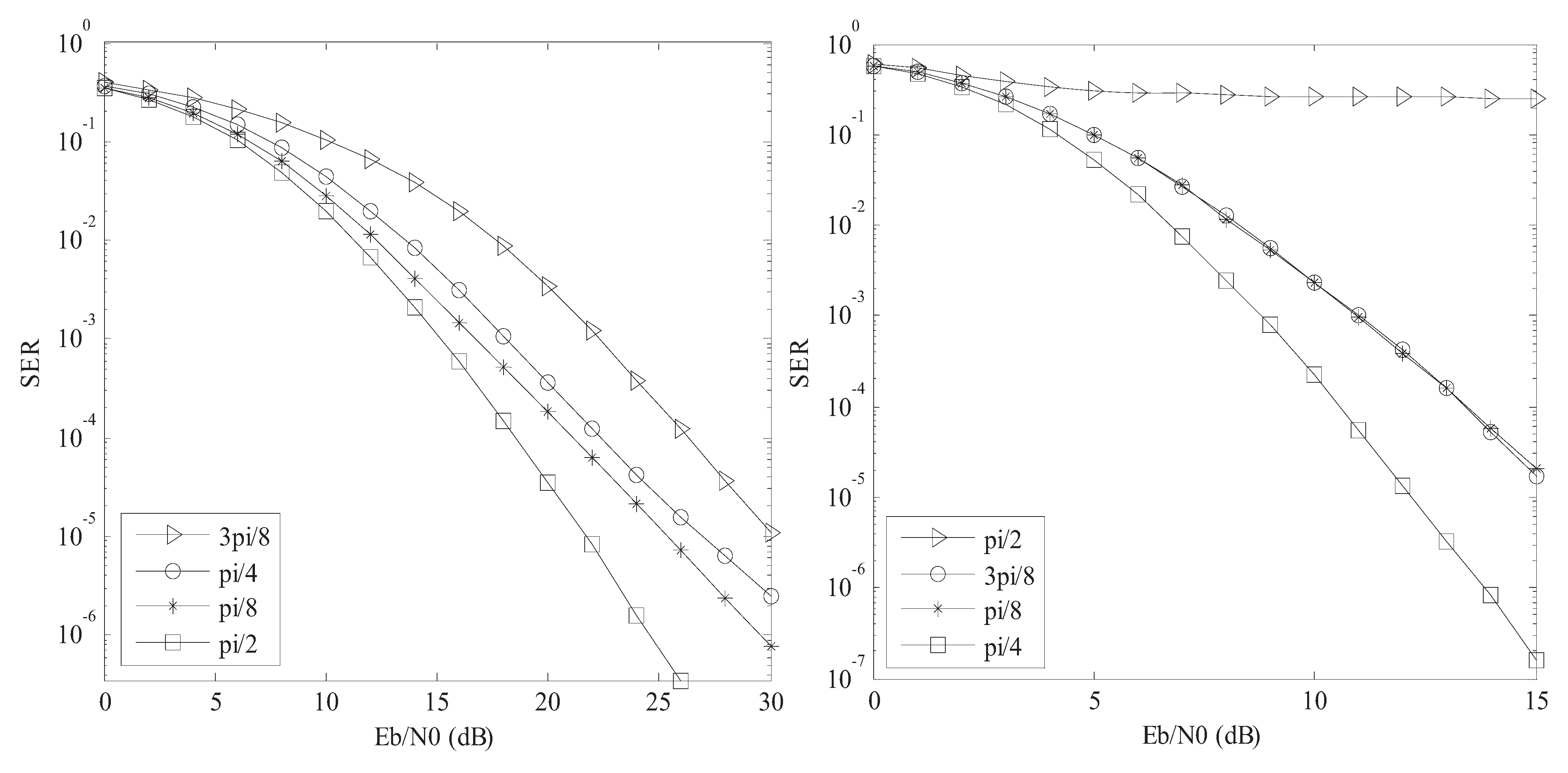
Figure 2 depicts the SERs of the RQSTBC scheme versus Eb/N0 values over a range of rotation angles, with the source using BPSK and 4-QAM, respectively.
Figure 2.
(a) The SERs of the RQSTBC scheme versus Eb/N0, for the rotation angles being equal to 1/8π, 1/4π, 3/8π, and 1/2π, with the source using BPSK (left). (b) The SERs of the RQSTBC scheme versus Eb/N0, for the rotation angles being equal to 1/8π, 1/4π, 3/8π, and 1/2π, with the source using 4QAM (right).
For the graphic clarification, not all of simulation results are shown. The optimal rotation angles (Here, the optimal rotation angle means that if the source selects half of the symbols from a constellation set rotated with this angle, the RQSTBC scheme would achieve the lowest SER performance bound.), which are used for the other simulations, are 1/2π for BPSK, and 1/4π for 4-QAM, respectively. Moreover, let the CGD between a pair of code words and from the RQSTBC in (5) be expressed by [10]:
If CGDmin(ϕ) represents the minimum CGD of the RQSTBC scheme, then, it could be found that this minimum CGD is a function of ϕ. Therefore, for a given constellation, to find an optima angle for any transmission scheme with QSTBC as its relay method, based on the determinant criterion, is equal to maximize CGDmin(ϕ) among all possible rotations. Manipulated as the same way in [3], we would derive the same results from (8), which are consistent with the results in [3].
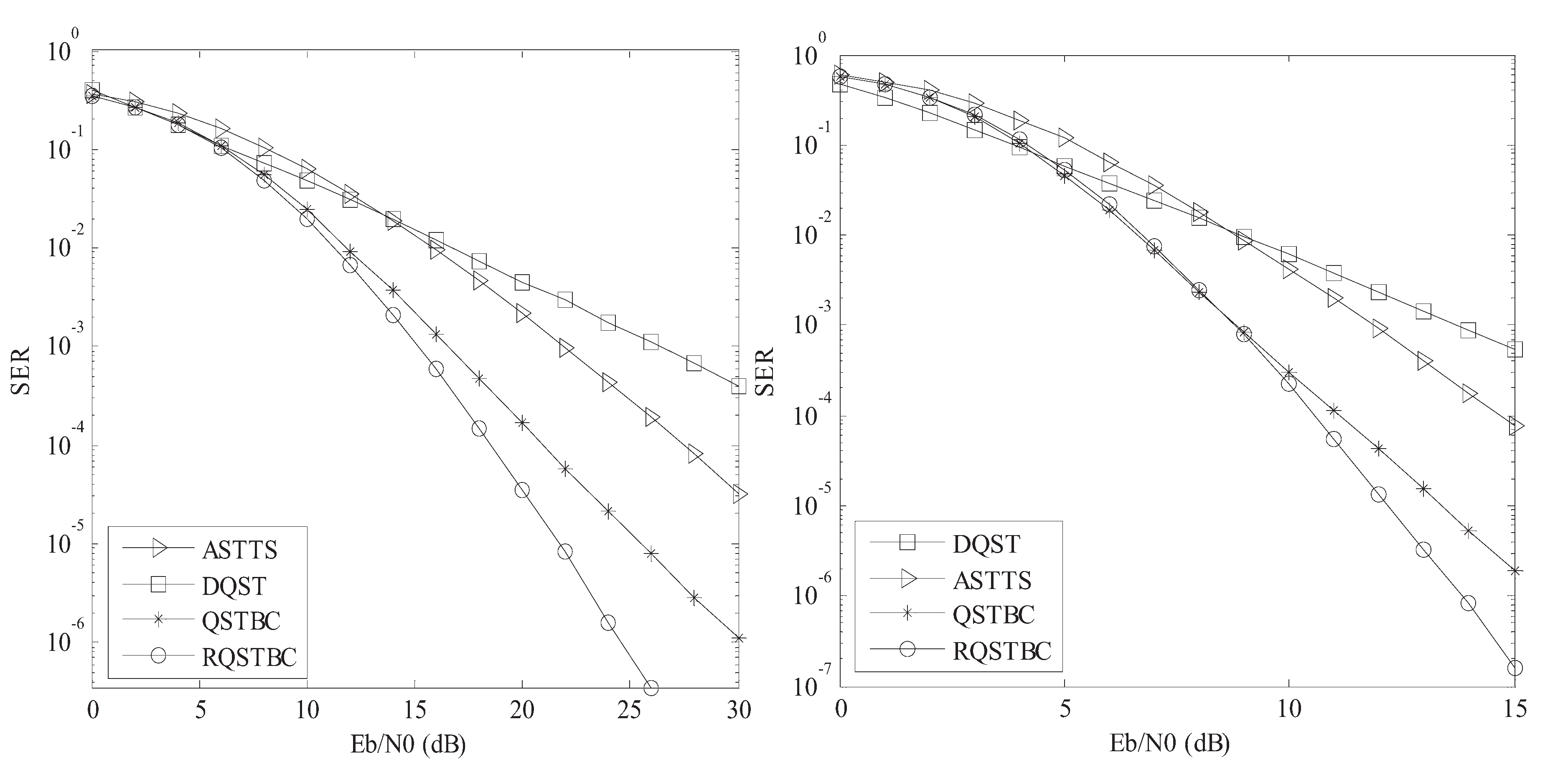
Figure 3 represents the SERs of four cooperative schemes versus Eb/N0, with the source using BPSK, the rotation angle of which for the RQSTBC scheme is 1/2π and 4-QAM, the rotation angle of which for the RQSTBC scheme is 1/4π, respectively.
Figure 3.
(a) The SERs of four cooperative schemes versus Eb/N0, with the source using BPSK, the rotation angle of which for the RQSTBC scheme is 1/2π (left). (b) The SERs of four cooperative schemes versus Eb/N0, with the source using 4QAM, the rotation angle of which for the RQSTBC scheme is 1/4π (right).
The SER of the proposed scheme is not only a few orders of magnitude lower than those of the ASTTS and the DQST but also lower than that of the QSTBC when the source uses BPSK. However, when the source employs 4-QAM, the SER of the proposed scheme is somewhat higher than those of the DQST and QSTBC when Eb/N0 is lower. This is because in this circumstance, the symbol, which is picked up from the rotated constellation, makes the destination more difficult to discern the truth. But, when EB/N0 is higher, the higher diversity order makes the proposed scheme achieve the best performance. These conclusions also coincide with the results provided by [10] for the rotated QSTBC at a scale factor since both of the proposed scheme and the ones in [10] are endowed with maximum transmission rate and full diversity though the scenario for them to operate is far from each other. Moreover, according to where Pe is the bit error rate [11] and SNR is signal-to-noise ratio, we can discover that the diversity gain of the proposed scheme approximates diversity order 4 as the SNR increases. Again, it demonstrates that the proposed scheme has the highest diversity gain. Its performance is superior to all other schemes considered in this context.
5. Conclusions
A new space-time block code asynchronous cooperative scheme is proposed. The rotated constellation is introduced to select half of transmitted signals at the source. The Jafarkhani structure combined with time-reversion is then extended to constitute a virtual array with maximum rate as well as full diversity. By doing that, the fast symbol-pair-wise ML decoder converges to the global optimum rapidly, accompanied by a lower SER with no observable gain in complexity. Moreover, if we assume that if the relays construct space-time block transmitted signals matrix in manner of the Tirkkonen, Boariu, and Hottinen structure [12], the Papadias-Foschini structure [13] in a two-hop cooperative communication system, we can generalize this system to universal RQSTBC systems with maximum rate. Furthermore, if we let Sl m(s1, …, sm) denote a m × m orthogonal matrix in complex symbols s1, s2, …, sm , we can extend the quasi-orthogonality matrix Sl in (5) by Sl2m of size 2m × 2m in complex symbols s1, s2, …, s2m, expressed as [10]:
where Sl A = Sl m(s1, s2, …, sm) and Sl B = Sl m(sm+1, sm+2, …, s2m). Then, with the same method similar to (4), we can generalize all RQSTBCs to be used in asynchronous cooperative systems. Meanwhile, the propose scheme can be relatively straightforwardly applied to analyze and discuss those systems.
Acknowledgments
The authors thank all of the reviewers for their valuable comments, which have considerably helped in improving the overall quality of the work presented in the revised paper. This work is supported by the key Programs of Natural Science Research of Universities of Anhui Province under Grant KJ2009A151 and the Natural Science Foundation of Anhui Province under Grant 11040606M125.
References
Stankovic, V.; Host-Madsen, A.; Xiong, Z. Cooperative diversity for wireless ad hoc networks. IEEE Signal Process. Mag.2006, 23, 37–49. [Google Scholar] [CrossRef]
Li, Q.; Li, G.; Lee, W.; Lee, M.; Mazzarese, D.; Clerckx, B.; Li, Z. MIMO techniques in WiMAX and LET: A feature overview. IEEE Commun. Mag.2010, 48, 86–92. [Google Scholar] [CrossRef]
Su, W.; Xia, X.-G. Signal constellations for quasi-orthogonal space-time block codes with full diversity. IEEE Trans. Inf. Theory2004, 50, 2331–2347. [Google Scholar] [CrossRef]
Li, Y.; Xia, X.-G. A family of distributed space-time trellis codes with asynchronous cooperative diversity. IEEE Trans. Commun.2007, 55, 790–800. [Google Scholar] [CrossRef]
Guo, X.; Xia, X.-G. Distributed linear convolutive space-time codes for asynchronous cooperative communication networks. IEEE Trans. Wirel. Commun.2008, 7, 1857–1861. [Google Scholar]
Li, Z.; Xia, X.-G. A simple Alamouti space-time transmission scheme for asynchronous cooperative systems. IEEE Signal Process. Lett.2007, 14, 804–807. [Google Scholar] [CrossRef]
Jafarkhani, H. A quasi-orthogonal space-time block code. IEEE Trans. Commun.2001, 49, 1–4. [Google Scholar] [CrossRef]
Jing, Y.; Hassibi, B. Distributed space-time coding in wireless relay networks. IEEE Trans. Wirel. Commun.2006, 5, 3524–3536. [Google Scholar] [CrossRef]
Jafarkhani, H. Space-Time Coding: Theory and Practice; Cambridge University Press: New York, NY, USA, 2005; pp. 110–125. [Google Scholar]
Zheng, L.; Tse, D.N.C. Diversity and multiplexing a fundamental tradeoff in multiple-antenna channels. IEEE Trans. Inf. Theory2003, 49, 1073–1096. [Google Scholar] [CrossRef]
Tirkkonen, O.; Boariu, A.; Hottinen, A. Minimal nonorthogonality rate 1 space-time block code for 3+Tx antennas. In Proceedings of IEEE Sixth International Symposium on Spread Spectrum Techniques and Applications, Parsippany, NJ, USA, September 2000; pp. 429–432.
Papadias, C.B.; Foschini, G.J. Capacity-approaching space-time codes for systems employing four transmitter antennas. IEEE Trans. Inf. Theory2003, 49, 726–732. [Google Scholar] [CrossRef]
Ni, L.-F.; Yao, F.-K.; Zhang, L.
A Rotated Quasi-Orthogonal Space-Time Block Code for Asynchronous Cooperative Diversity. Entropy2012, 14, 654-664.
https://doi.org/10.3390/e14040654
AMA Style
Ni L-F, Yao F-K, Zhang L.
A Rotated Quasi-Orthogonal Space-Time Block Code for Asynchronous Cooperative Diversity. Entropy. 2012; 14(4):654-664.
https://doi.org/10.3390/e14040654
Chicago/Turabian Style
Ni, Liang-Fang, Fu-Kui Yao, and Li Zhang.
2012. "A Rotated Quasi-Orthogonal Space-Time Block Code for Asynchronous Cooperative Diversity" Entropy 14, no. 4: 654-664.
https://doi.org/10.3390/e14040654
Article Metrics
No
No
Article Access Statistics
For more information on the journal statistics, click here.
Multiple requests from the same IP address are counted as one view.
Ni, L.-F.; Yao, F.-K.; Zhang, L.
A Rotated Quasi-Orthogonal Space-Time Block Code for Asynchronous Cooperative Diversity. Entropy2012, 14, 654-664.
https://doi.org/10.3390/e14040654
AMA Style
Ni L-F, Yao F-K, Zhang L.
A Rotated Quasi-Orthogonal Space-Time Block Code for Asynchronous Cooperative Diversity. Entropy. 2012; 14(4):654-664.
https://doi.org/10.3390/e14040654
Chicago/Turabian Style
Ni, Liang-Fang, Fu-Kui Yao, and Li Zhang.
2012. "A Rotated Quasi-Orthogonal Space-Time Block Code for Asynchronous Cooperative Diversity" Entropy 14, no. 4: 654-664.
https://doi.org/10.3390/e14040654


 for any 0 ≤ l ≠ m ≤ N − 1, which, based on the analysis of [9], implies its diversity gain 4(1-loglogP/P), approaching the diversity order 4 when the total power P is large. Meanwhile, if in the proposed scheme, the source randomly picks up the symbols from a signal constellation set, the resulting scheme is of QSTBC characteristic, that is to say, it cannot guarantee (Sl − Sm) is full rank such that its diversity order is smaller than 4. Similarly, it would be inferred that the ASTTS scheme obtains diversity order 2. Since the diversity order determines the slope of the symbol error rate (SER) curve, the performance of the RQSTBC scheme is superior to those of QSTBC scheme and ASTTS scheme, which would be verified in our simulation in next section.

