Entropy-Based Block Processing for Satellite Image Registration

1
School of Information and Mechatronics, Gwangju Institute of Science and Technology (GIST), 123 Cheomdan gwagiro, Buk-Gu, Gwangju 500-712, South Korea
2
Satellite Data Cal/Val Team, Korea Aerospace Research Institute, 45 Eundong Yusunggu, Daejon 305-333, South Korea
*
Author to whom correspondence should be addressed.
Entropy 2012, 14(12), 2397-2407; https://doi.org/10.3390/e14122397
Submission received: 8 October 2012
/
Revised: 14 November 2012
/
Accepted: 19 November 2012
/
Published: 27 November 2012
Abstract
:Image registration is an important task in many computer vision applications such as fusion systems, 3D shape recovery and earth observation. Particularly, registering satellite images is challenging and time-consuming due to limited resources and large image size. In such scenario, state-of-the-art image registration methods such as scale-invariant feature transform (SIFT) may not be suitable due to high processing time. In this paper, we propose an algorithm based on block processing via entropy to register satellite images. The performance of the proposed method is evaluated using different real images. The comparative analysis shows that it not only reduces the processing time but also enhances the accuracy.
1. Introduction
Image registration is an important task in many computer vision applications such as fusion systems, 3D shape recovery and earth observation. Particularly, satellite image registration is a challenging task due to large image size and huge resources consumption. A satellite image can occupy hundreds of megapixels in several spectral bands. Though the high resolution images provide more details, it is not efficient to process the whole image for registration due to the limited resources. Moreover, common global transformations provide limited performance on high resolution image.
Mikojclyk and Schmid [1] evaluated the performance of local descriptors and showed that scale-invariant feature transform (SIFT) provides the best performance with respect to other descriptors, including shape context [2], steerable filter [3], differential invariants [4], and spin image [5]. In the literature, SIFT [6,7] has been used to register spectral images. The major drawback of the SIFT-based method is its high time complexity. In order to reduce its processing time, a few attempts have been made, such as principal component analysis SIFT (PCA-SIFT) [8] and speeded up robust features (SURF) [9]. These methods are able to speed up the basic SIFT method; however, the accuracy is deteriorated [10]. In addition, a few approaches based on fast-matching techniques have been proposed to overcome these problems, especially to improve the speed. These works include the nearest neighbor distance ratio (NNDR) [1], which uses the threshold for the ratio between the first and the second nearest neighbor descriptors, and the kd-tree [7,11], which is widely used to determine the feature index and hierarchical structure to find the nearest neighbor relationships and similarity query in a set of multi-dimensional points. These methods may provide gains in efficiency but they do not improve the speed for an exhaustive search in a 10-dimensional or higher space. Moreover, the above-mentioned feature-based methods and area-based methods [12] are not suitable for satellite image registration due to their expensive computation and large memory requirement.
In order to overcome these above-mentioned problems, in this paper, we propose an algorithm based on SIFT and block processing to register satellite images. The performance of the proposed method is evaluated using different real images. The comparative analysis shows that it not only reduces the processing time but also enhances the accuracy.
2. Scale-invariant Feature Transform
The SIFT detector extracts blob/region in a scale space. In the first step, the scale space is constructed by convolution between an input image and a variable-scale Gaussian [13,14]
In the second step, the blob is detected as the local extrema of the DoG scale-space.
To extract the local maxima in a DoG scale-space, 3 × 3 × 3 neighborhoods are computed for each point 3 × 3 window. The points having local maxima or minima are considered keypoints. In the third step, keypoints are further refined by eliminating low contrast and edge responses. In the fourth step, each candidate keypoint is assigned magnitude and orientation , such that
In the last step, the descriptors are constructed by computing the histogram of the image gradient and orientations. For orientation invariance, the sampling grid for the histograms is rotated to the main orientation of each keypoint. The grid is a 4 × 4 array of 4 × 4 sample cells of 8-bin orientation histograms, which produces 128-dimensional feature vectors. To achieve the invariance of illumination changes, the descriptor is normalized with respect to the unit length. Gaussian weighted function is applied to give less importance to gradients farther from the descriptor center and to avoid sudden changes. SIFT-based methods have problems such as high computational complexity. During the detection process, image size affects the processing time. SIFT uses the Gaussian convolution and sampling iteratively. The SIFT descriptor is a 128-dimensional vector. If the detector extracts 100 features, then the descriptor dimension is 100 × 128. Euclidean distance is used for descriptor matching. It uses the first and the second nearest neighbor descriptors. If the descriptor dimension is high, the matching process will require high processing time.
3. Proposed Method
In the case of satellite image registration, feature extraction using whole image is not suitable for registration. Table 1 depicts the processing time for each major step involved in image registrations. Table 1 shows that the majority of time is consumed by the descriptor step and the matching step due to the high dimensionality; the descriptor step consumes 36.45% and the matching step consumes 32.70% of the time, respectively.

| Step | Process | Time Consumed |
|---|---|---|
| Detector | Scale space | 96.64 |
| Difference of Gaussian (DoG) | ||
| DoG extrema | ||
| Localization: Filter edge and low contrast responses | ||
| Descriptor | Assign keypoints orientations | 114.17 |
| Histogram, Normalization, Gaussian weighting | ||
| Matching | Feature matching | 102.42 |
3.1. Block Processing
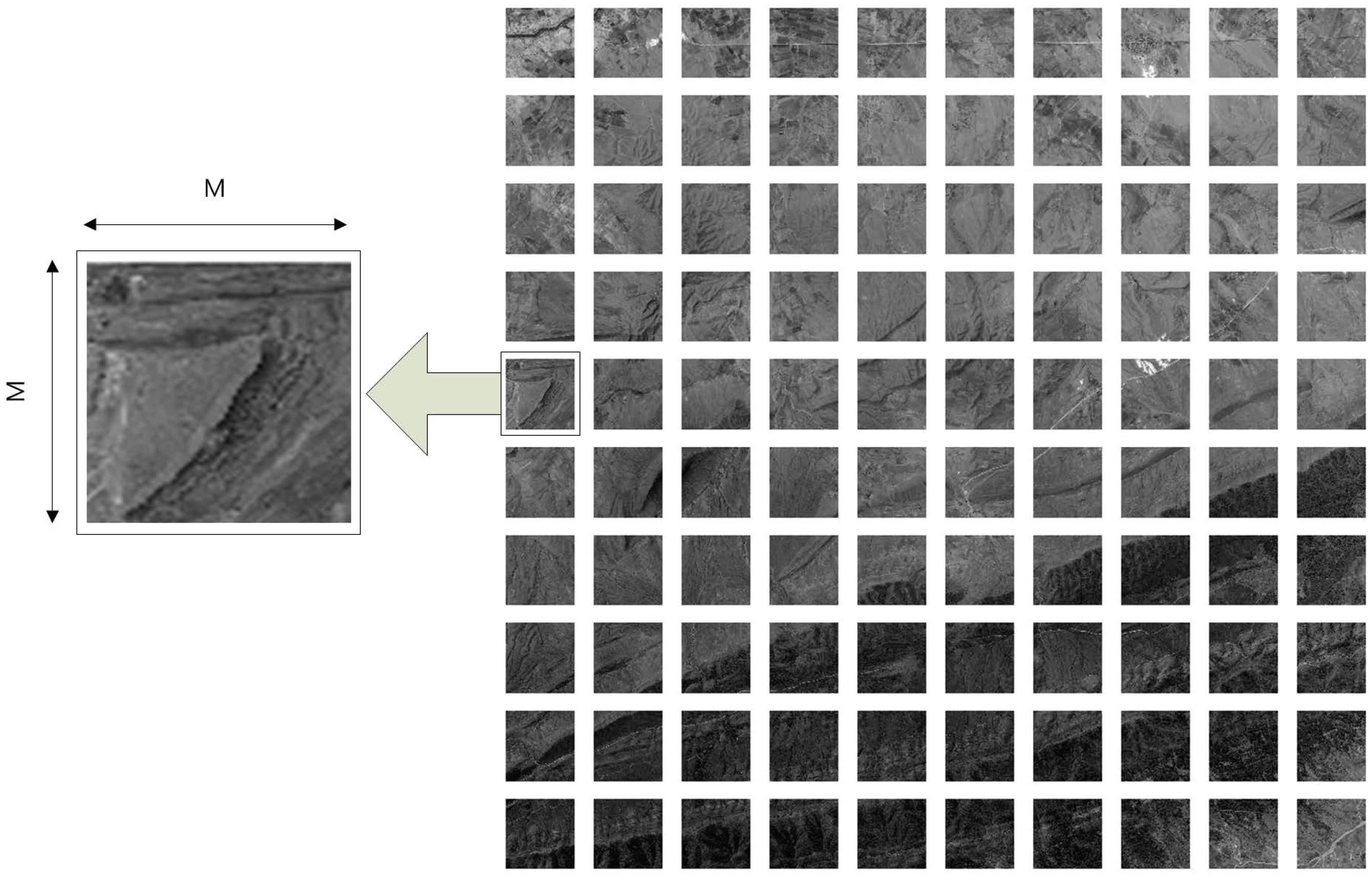
To reduce the descriptor size and thus reduce computational time, we divide the image into small blocks as shown in Figure 1.
Mathematical representation of small image block is as follows:
where M is the size of image block . Table 2 shows the processing time for various sizes of the image block. The processed image size also affects the computational time; however, a small image block allows small descriptor and small matching area that consume less processing time. For example, the number of features in a image block is 43, while the image block has 167 features. Larger image has more information and can extract more features. This phenomenon is natural and understandable. It means that the descriptor size is for the image block, and the image block has a descriptor size of . Smaller image block allows less dimensionality due to the number of extracted features. In the case of image block size, the processing time is 0.040162 s, while the image block size takes 0.163099 s. Hence, the block size plays an important role in determining the overall accuracy and speed. Generally, a smaller block size reduces the processing time, although it may not provide optimal results. In some cases, a smaller block size does not provide any control points due to the smaller overlapped area, whereas a larger block size consumes time. Therefore, it is important to determine the optimal block size.
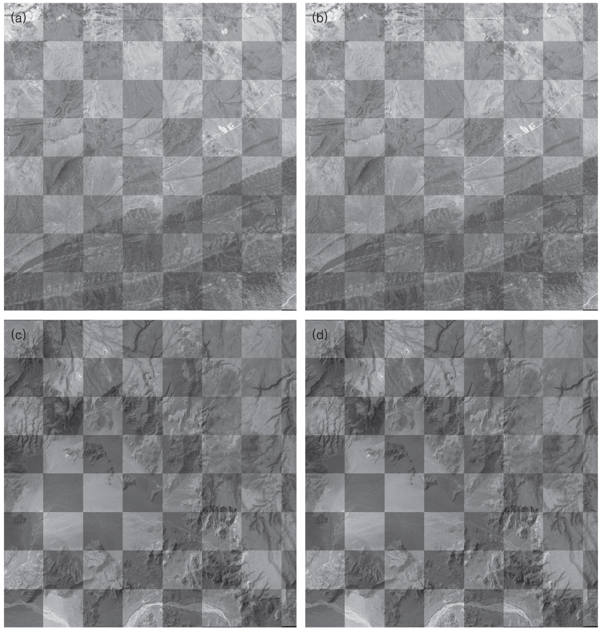
Figure 1.
Partitioning of sample satellite image.

Table 2.
Comparison of the number of features and computational time for non-block and block-based processing.
| Block size | Non-block | |||
|---|---|---|---|---|
| The number of features | 5532 | 3361 | 5756 | 6987 |
| Processing time(s) | 9531.3993 | 436.4116 | 497.1570 | 520.8296 |
3.2. Determination of Optimal Block Size
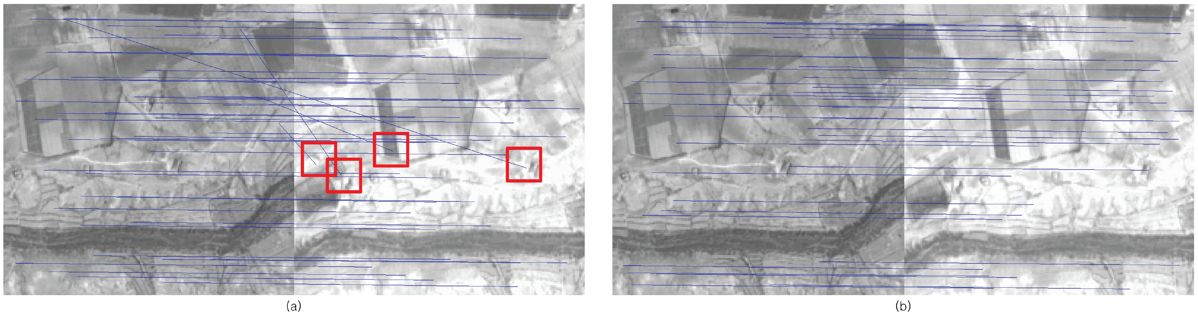
The accuracy of the block-processing image registration method depends on the block size and the number of features extracted from the block. In literature [15,16,17], the effect of the number of features was analyzed in terms of registration error and accuracy, in which a larger number of features was found to provide better results. In order to determine optimal block size (OBS), whole image processed features (WF) are compared with block processed features (BF). Even the number of WF is similar to BF, the accuracy of the registration results may differ, because the use of block processing helps to reduce false matching features with geometrical constraint. Figure 2 shows the comparison of matching features between non-block processing and block-based processing. From the figure, we can observe that the block-based method provides more accurate matching features, whereas a non-block processing method has false matching features (red square box). In the proposed approach, if the BF is greater than WF, then this block size is considered as the optimal block size. Otherwise, the block size is increased by adding square blocks (SB). In our case, we set .
The process is iterated until the criterion is fulfilled with the maximum block size constraint. The maximum block size constraint is determined by entropy, which is defined as:
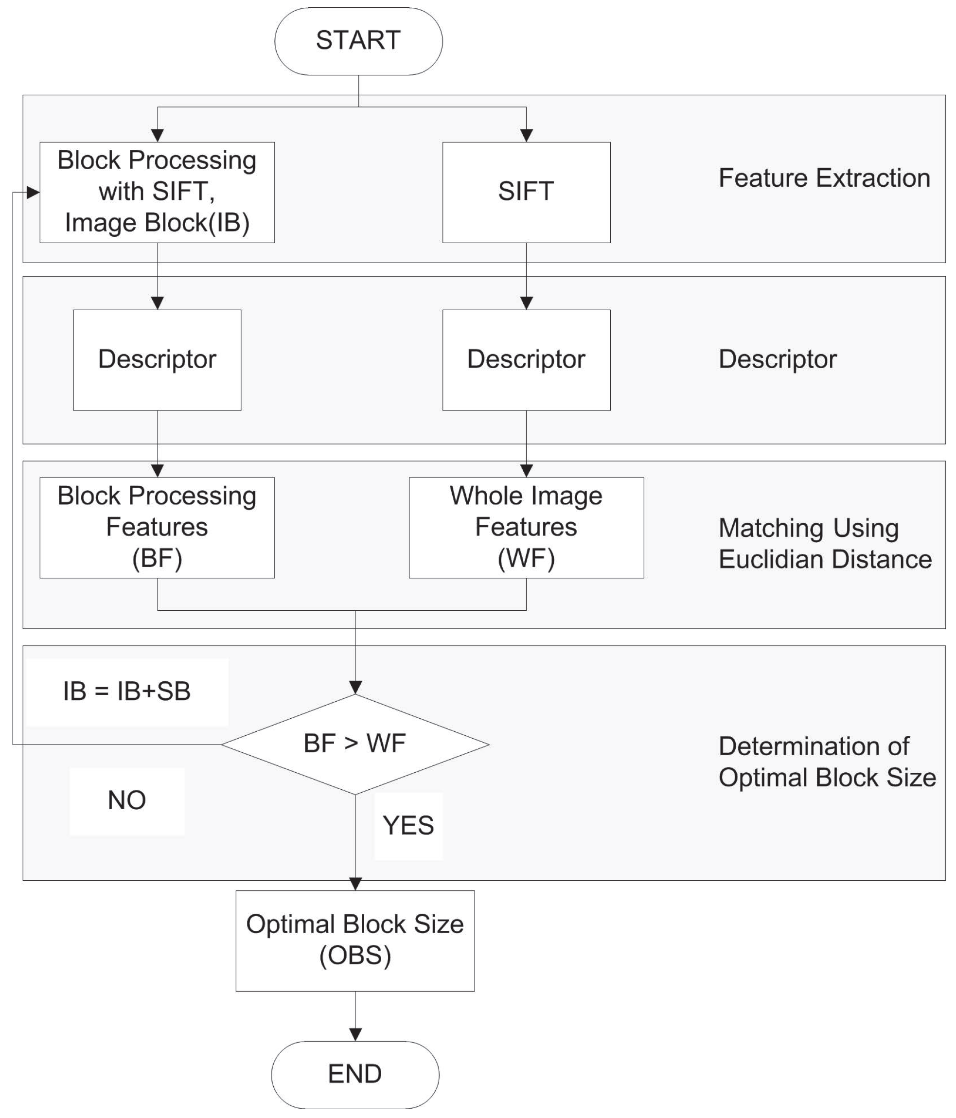
where p is the frequency of the grey level. E takes its maximum value when all p are equal. By this definition, more pixel variation (more information) will have greater entropy. In Figure 3, the histogram of the grey level values is shown. It can be observed that Figure 3c has the greatest pixel variation. Figure 4 shows the entropy along various block sizes. From the figure, we can observe that the block size has maximum entropy. By this analysis, is used as the maximum block size for the determination of the optimal block size (OBS). The proposed block-based algorithm is represented in Figure 5. Through various experiments, we determine the optimal block size to be . In order to extract the features, the panchromatic reference image and the multi-spectral sensed image are used. Then, matching points are selected by the Euclidean distance between descriptors.
where , are the first and the second descriptors, respectively.
Figure 2.
Matching features comparison: (a) non-block processing; (b) block processing.

Figure 3.
Histogram of each block size: (a) ; (b) ; (c) .
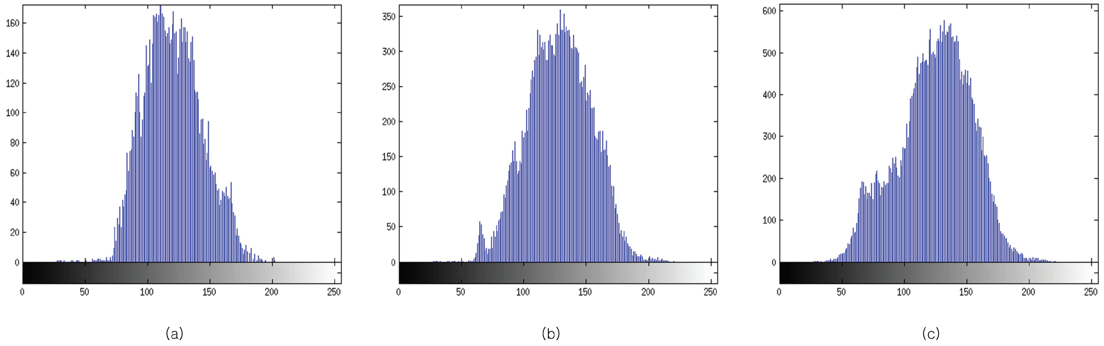
Figure 4.
Entropy plot for various block sizes.
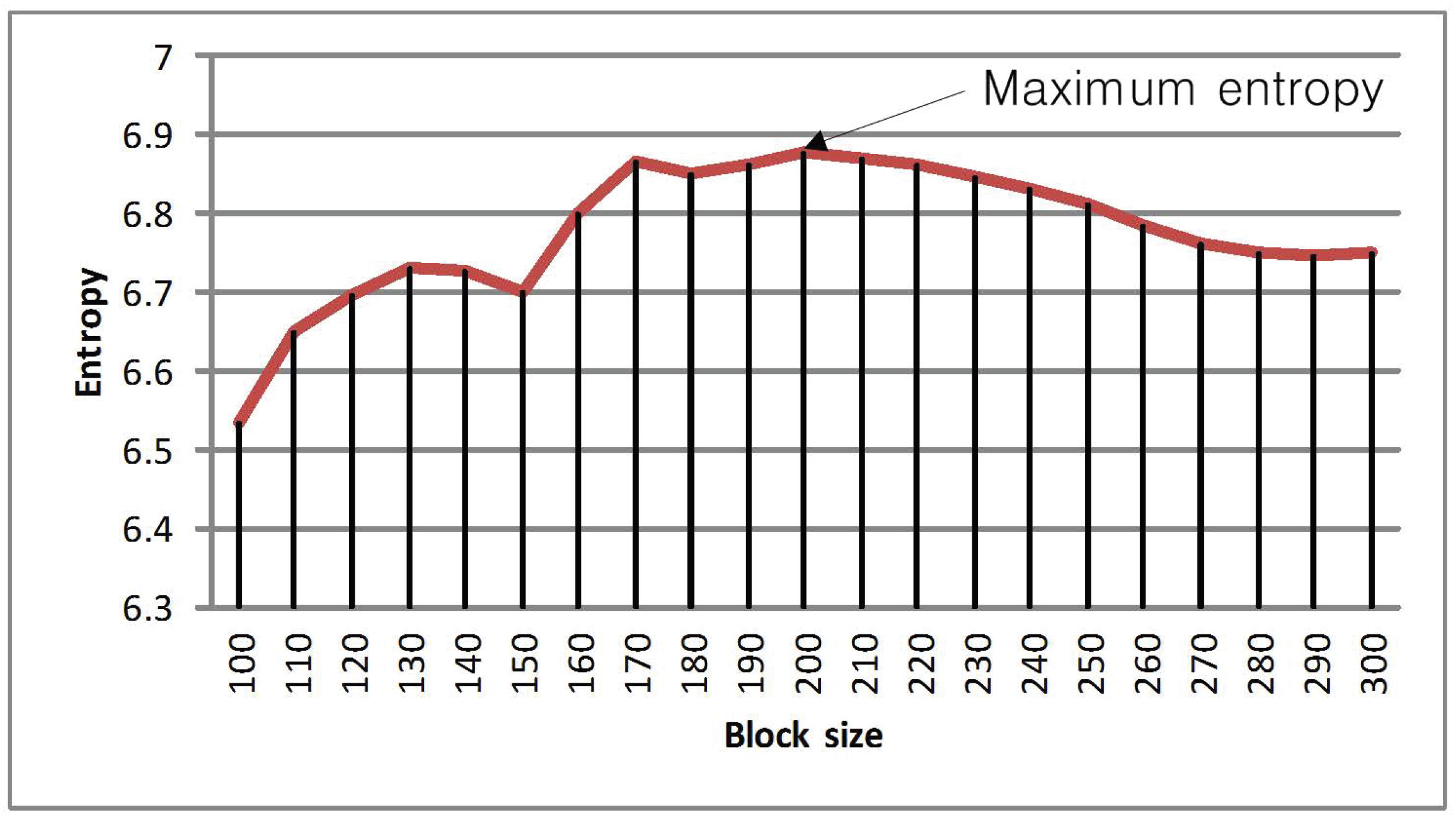
Figure 5.
Flowchart of the block-based algorithm.

4. Experimental Results
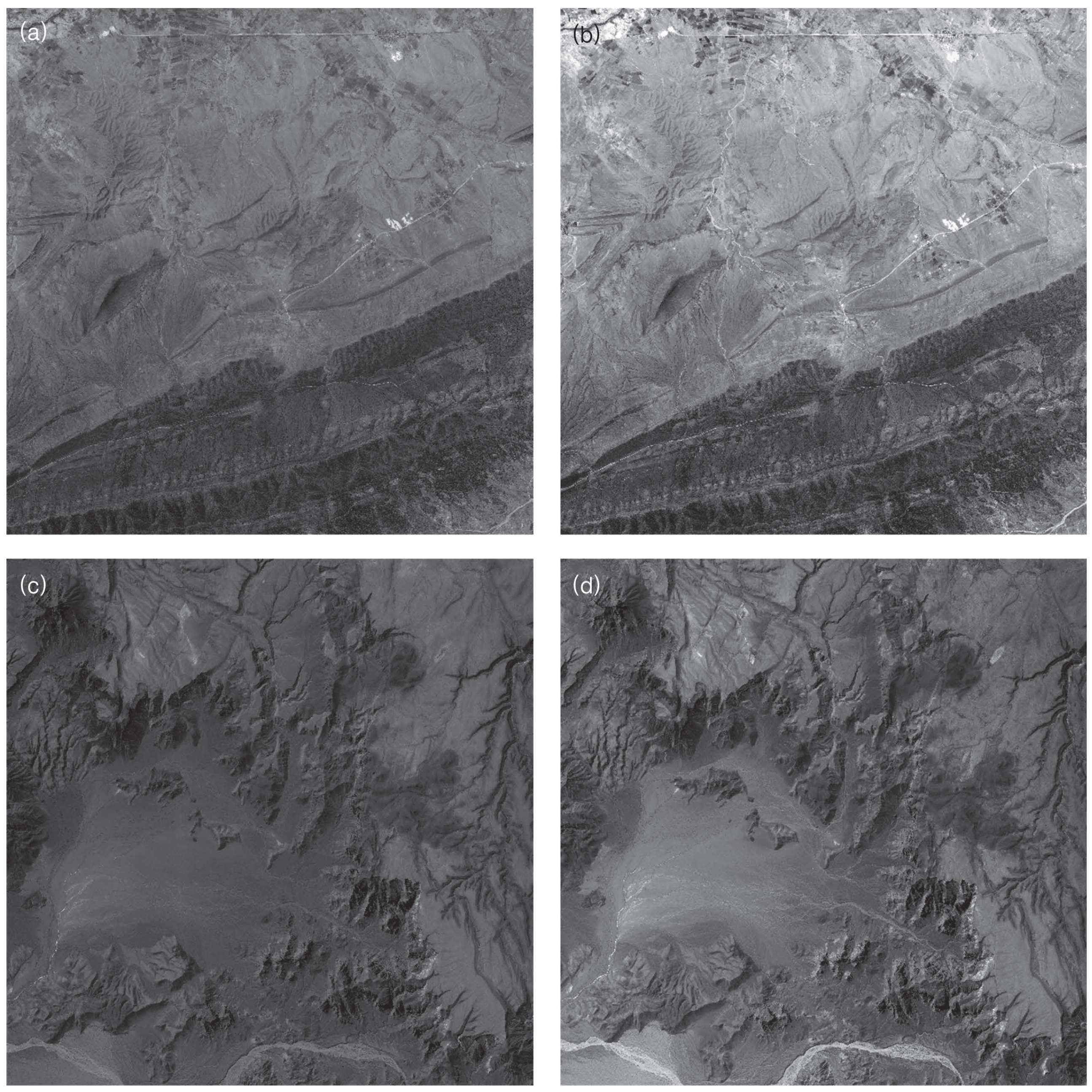
The size of the panchromatic image is approximately pixels and it is 500 MB large. The multi-spectral image has a size of and it is 40 MB large, as shown in Figure 6. The matching ratio parameter is 10. If the matching ratio is decreased, the number of matching points will increase with more processing time required and less accurate feature points. The SIFT parameters may affect the performance of feature detection and descriptor construction. In our case, we modified the original SIFT parameters due to the need for more feature points. The values for main parameters are described in Table 3. Figure 7 presents the composite images of Samples 1 and 2; however, it is not clear how much they are accurately warped. In medical image, these composite images are used for visual comparison of registration accuracy. It is not a suitable method for remote sensing images due to the large image size. In Figure 8, the accuracy between conventional and proposed methods is clearer and distinguishable. The figures are in color (Red: Registered output image of multi-spectral , Green: panchromatic , Blue: panchromatic ). In the case of accurate registration, there should be less red color component in the RGB image, as it can be observed in the output image of the proposed method shown in Figure 8b and 8d. Table 4 shows the number of features and processing time for different block sizes. It also shows the comparison of registration accuracy using root mean square error (RMSE). The proposed method provides the lowest RMSE value and more distinct features as compared with the non-block processing method. In addition, the processing time of the proposed method is much shorter than the non-block method.
Figure 6.
Test images: Sample 1 (first row), Sample 2 (second row), panchromatic images (first column), multi-spectral images (second column).
Figure 6.
Test images: Sample 1 (first row), Sample 2 (second row), panchromatic images (first column), multi-spectral images (second column).

| Parameter | Value |
|---|---|
| (a) Scale space | |
| Number of octaves in scale space | 9 |
| Number of scale per octave | 3 |
| Nominal pre-smoothing | 0.05 |
| (b) Detector | |
| Local extrema threshold | 0.001 |
| Local extrema localization threshold | 2 |
| (c) Descriptor | |
| Descriptor window magnification | 3.0 |
| Number of spatial bins | 4 |
| Number of orientation bins | 8 |
Figure 7.
Composite images: (a) non-block method of Sample 1; (b) proposed method of Sample 1; (c) non-block method of Sample 2; and (d) proposed method of Sample 2.
Figure 7.
Composite images: (a) non-block method of Sample 1; (b) proposed method of Sample 1; (c) non-block method of Sample 2; and (d) proposed method of Sample 2.

Figure 8.
Samples of warped RGB images: sample 1 (first row), sample 2 (second row), non-block processing images (first column), proposed method (second column).
Figure 8.
Samples of warped RGB images: sample 1 (first row), sample 2 (second row), non-block processing images (first column), proposed method (second column).
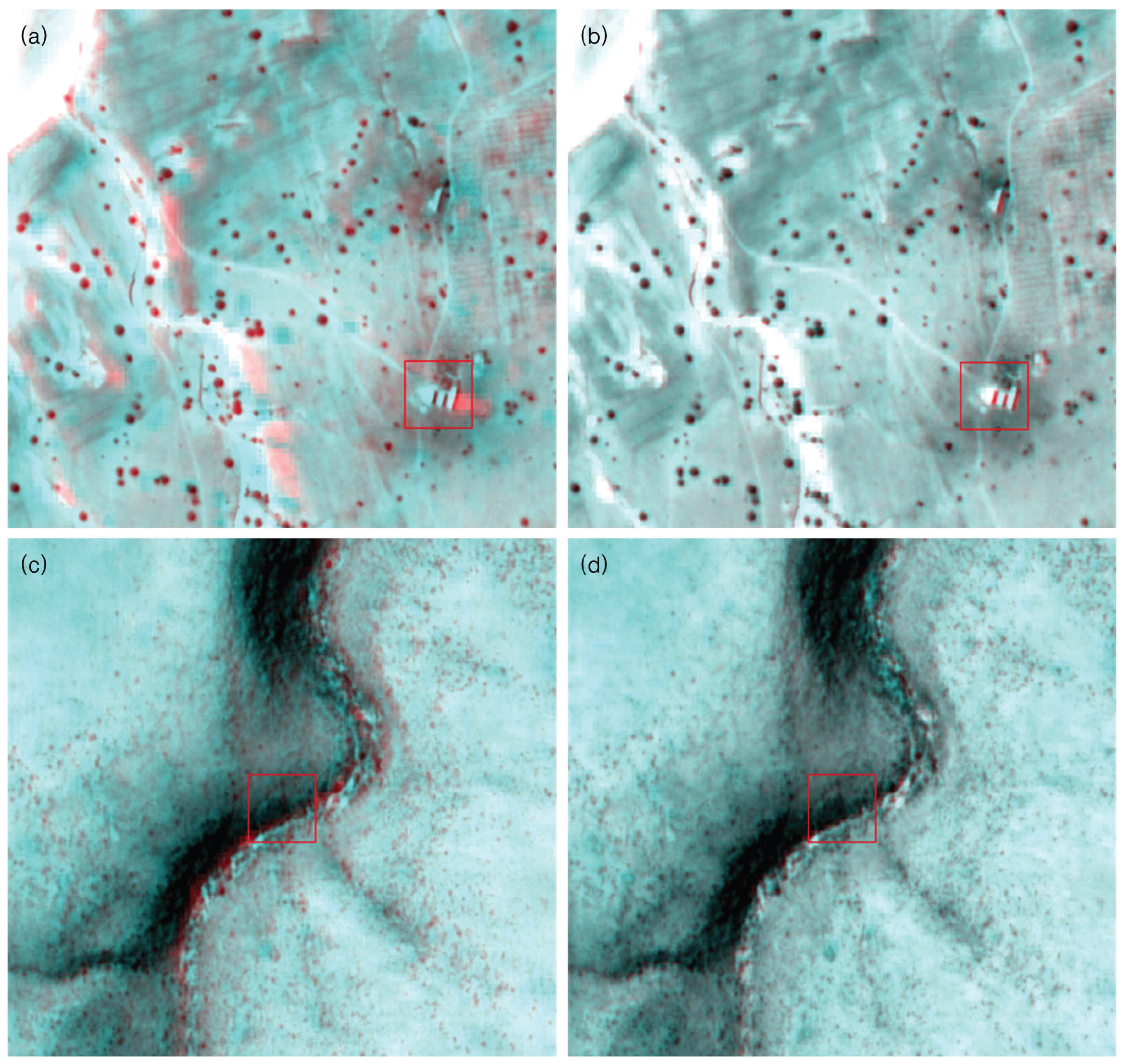
Table 4.
The number of features and computational time comparison for non-block and block-based processing.
| Block size | Non-block | |||
|---|---|---|---|---|
| (a) Sample 1 | ||||
| Total matching points | 5532 | 3361 | 5756 | 6987 |
| Processing time(s) | 9531.3993 | 436.4116 | 497.1570 | 520.8296 |
| RMSE | 0.3760 | 0.3536 | 0.3010 | 0.3075 |
| (a) Sample 2 | ||||
| Total matching points | 1742 | 1206 | 2062 | 2351 |
| Processing time(s) | 8404.5322 | 295.9979 | 322.8102 | 338.1715 |
| RMSE | 0.7987 | 0.5963 | 0.4597 | 0.4830 |
5. Conclusions
In this letter, we have proposed a method for the registration of satellite images based on SIFT and block processing. The proposed block-based method is capable of providing better results than non-block processing. The experimental results have demonstrated that the proposed method is much faster and more accurate than non-block processing method.
Acknowledgment
This research was supported by Space Core Technology Development Program through the National Research Foundation of Korea by the the Ministry of Education, Science and Technology (No. 2012M1A3A3A02033352).
References
- Mikolajczyk, K.; Schmid, C. A performance evaluation of local descriptors. IEEE Trans. Pattern Anal. Mach. Intell. 2005, 27, 1615–1630. [Google Scholar] [CrossRef] [PubMed]
- Belongie, S.; Malik, J.; Puzicha, J. Shape matching and object recognition using shape contexts. IEEE Trans. Pattern Anal. Mach. Intell. 2002, 24, 509–522. [Google Scholar] [CrossRef]
- Freeman, W.; Adelson, E. The design and use of steerable filters. IEEE Trans. Pattern Anal. Mach. Intell. 1991, 13, 891–906. [Google Scholar] [CrossRef]
- Koenderink, J.; van Doorn, A. Representation of local geometry in the visual system. Biol. Cybern. 1987, 55, 367–375. [Google Scholar] [CrossRef] [PubMed]
- Lazebnik, S.; Schmid, C.; Ponce, J. A sparse texture representation using affine-invariant regions. In Proceedings of the Computer Vision and Pattern Recognition, IEEE Computer Society Conference, Madison, USA, 18-20 June 2003; Volume 2, pp. 319–324.
- Lowe, D. Object Recognition From Local Scale-Invariant Features. In Proceedings of the Computer Vision and Pattern Recognition, IEEE Computer Society Conference, Ft. Collins, USA, 23-25 June 1999; Volume 2, pp. 1150–1157.
- Lowe, D. Distinctive image features from scale-invariant keypoints. Int. J. Comput. Vision 2004, 60, 91–110. [Google Scholar] [CrossRef]
- Ke, Y.; Sukthankar, R. PCA-SIFT: A More Distinctive Representation for Local Image Descriptors. In Proceedings of the Computer Vision and Pattern Recognition, IEEE Computer Society Conference, Washington, D.C., USA, 27 June - 2 July, 2004; Volume 2, pp. 506–513.
- Bay, H.; Ess, A.; Tuytelaars, T.; Van Gool, L. Speeded-up robust features (SURF). Computer vision and image understanding 2008, 110, 346–359. [Google Scholar] [CrossRef]
- Juan, L.; Gwun, O. A comparison of sift, pca-sift and surf. Int. J. Image Process. 2009, 3, 143–152. [Google Scholar]
- Friedman, J.; Bentley, J.; Finkel, R. An algorithm for finding best matches in logarithmic expected time. ACM Trans. Math. Softw 1977, 3, 209–226. [Google Scholar] [CrossRef]
- Vila, M.; Bardera, A.; Feixas, M.; Sbert, M. Tsallis mutual information for document classification. Entropy 2011, 13, 1694–1707. [Google Scholar] [CrossRef]
- Koenderink, J. The structure of images. Biol. Cybern. 1984, 50, 363–370. [Google Scholar] [CrossRef] [PubMed]
- Lindeberg, T. Scale-space Theory in Computer Vision; Springer: Berlin/Heidelberg, Germany, 1993. [Google Scholar]
- Bernstein, R. Image geometry and rectification. Man. Remote Sens. 1983, 1, 873–922. [Google Scholar]
- Chen, H.; Arora, M.; Varshney, P. Mutual information-based image registration for remote sensing data. Int. J. Remote Sens. 2003, 24, 3701. [Google Scholar] [CrossRef]
- Hong, G.; Zhang, Y. Wavelet-based image registration technique for high-resolution remote sensing images. Comput. Geosci. 2008, 34, 1708–1720. [Google Scholar] [CrossRef]
© 2012 by the authors; licensee MDPI, Basel, Switzerland. This article is an open access article distributed under the terms and conditions of the Creative Commons Attribution license (http://creativecommons.org/licenses/by/3.0/).
Share and Cite
MDPI and ACS Style
Lee, I.; Seo, D.-C.; Choi, T.-S. Entropy-Based Block Processing for Satellite Image Registration. Entropy 2012, 14, 2397-2407. https://doi.org/10.3390/e14122397
AMA Style
Lee I, Seo D-C, Choi T-S. Entropy-Based Block Processing for Satellite Image Registration. Entropy. 2012; 14(12):2397-2407. https://doi.org/10.3390/e14122397
Chicago/Turabian StyleLee, Ikhyun, Doo-Chun Seo, and Tae-Sun Choi. 2012. "Entropy-Based Block Processing for Satellite Image Registration" Entropy 14, no. 12: 2397-2407. https://doi.org/10.3390/e14122397