1. Introduction
The most recent surveys ascertain that the demand for building cooling has been increasing in the past few years and will continue to do so dramatically in the near future. The AUDITAC study [
1,
2,
3] showed that in 1990 about 10,000 GWh of primary energy were consumed in Europe by small Room Air Conditioners (RAC) (<12 kW) with 540 Mm
2 (million square meters) of cooled floor area and that in 2020 this value is expected to increase by a factor of four to about 44,000 GWh, with a cooled area of 2,400 Mm
2. Although high, this value does not include centralized systems, generally installed in large commercial buildings.
The reasons for such a forecast in cooling demand are several, but mostly due to the more and more popular tendency of modern architecture to use glass façade surface areas, higher demand for comfort, quantitative increase of office and service buildings, increasing number of electric appliances and, in one word, expected economic growth.
All that implies energy, economic and environmental consequences. The technologies currently available are those based on electrically driven compression chillers and thermally driven sorption chillers. Actually, with electric chillers being dominant, the concern is about electricity consumption and, more importantly, black-out risks which may occur in large urban areas, when several thousands of small and large size air-conditioning units are likely to be activated almost simultaneously during the hottest hours of the day in the summer season.
The shift to thermally driven chillers and/or the district cooling may be an option, although not effective, considered the limited market share in perspective for these technologies. Potentially better could be a substantial increase in the energy efficiency of chillers and the air-conditioning plant schemes.
This paper deals more with the latter than with the former issue, in the sense that we will analyze the most common air-conditioning systems in order to detect the processes and/or components most responsible of the thermodynamic drawbacks and pinpoint the potential for the improvement of energy efficiency.
2. General Overview on the First and Second Law Efficiency of Cooling Technologies
Air conditioning for the summer season mostly relies on cooling and cooling is mostly based on either electrically-driven or thermally-driven chillers. The energy indicator for both is the well known Coefficient of Performance (COP) which, for the two technologies, is defined respectively as:
being
Q the cooling power (useful effect),
Pel the electricity required to drive the chiller and
Qg the thermal power offered to the generator of the thermal (or sorption) chiller. Actual values for the COP lay in the following range: COP
el = 2 ÷ 4; COP
th = 0.6 ÷ 1.2.
On the basis of these numbers one should not conclude that electric chillers are better than thermal chillers, because such a comparison is not properly stated. Indeed the two definitions of COP refer to energy of different quality: heat (
Qg) for the sorption machine and electricity (
Pel) for the compression machine. A more rational basis for comparison is the Primary Energy Ratio, defined as the ratio of the delivered useful cold (
Q) to the Primary Energy (
PE) consumption to drive the machine:
The
PE in the currently accepted definition is “energy that has not been subjected to any conversion or transformation process” [
4], therefore one may consider fossil fuels as sources of PE. As a result, the PER may be assessed by combining the previous equations, such as:
Being
![Entropy 12 00859 i004]()
the efficiency of the electric system (nationwide efficiency) and
![Entropy 12 00859 i005]()
the efficiency of the boiler driving the sorption chiller. Rough numbers may be as follows:
ηel = 0.40 (recommended value for Europe);
ηg = 0.90, thus:
PERel = (2 ÷ 4) · 0.4 = 0.8 ÷ 1.6 and
PERth = (0.7 ÷ 1.2) · 0.9 = 0.63 ÷ 1.08.
Looking at these results one may conclude that current technologies for cooling are quite acceptable, and in certain cases (for PER > 1), apparently able to provide the user with a cooling energy even greater than the exploited PE. Of course there is no violation of the physics laws, since COPs do not include, by definition, the energy taken from the environment.
A quite different picture appears when one looks at the problem from a second law perspective. In this case we have to judge the technologies on the basis of the exergy efficiency, defined as the ratio of the exergy required by the end-use to that exploited to drive the system. Now the purpose is to extract from the building the heat Q in order to maintain the interior spaces at temperature T (e.g., T = 26 °C = 299 K) against an outdoor (environment) temperature To (e.g., To = 33 °C = 306 K).
For an electric chiller the exploited exergy is Pel (electric energy is pure exergy). For a sorption chiller, the thermodynamic potential which drives the machine may be assessed as Qg (1– To/Tg ). The maximum temperature Tg of the energy source, for a chiller powered by a conventional gas boiler, may be assumed equal to the flame temperature (e.g., Tg = 1,500 K).
The results reveal that, under the light of the 2nd law, the current technologies for cooling are not as good as described, via COP and REP, by the first law. The poor exergy efficiencies tell us something about the improper use we make of the energy sources in this field. The sad thing is that these technologies are also the most widespread in the world and involve both the civil and the industrial sectors.
The deep reasons of such outcomes can be clarified by conducting a detailed analysis of air conditioning systems. That will be done by using the exergy approach to the most common HVAC plant schemes. Detecting the most responsible processes and/or components for thermodynamic inefficiencies will give us the opportunity either to improve the design or to find new technologies.
3. Basic Formulas for Exergy Analysis of Psychrometric Processes
Air conditioning systems are complex systems able to perform such a sequence of thermodynamic processes to bring an air stream from natural outdoor conditions to suitable supply conditions. To put HVAC systems under the light of the 2nd law, it is necessary to evaluate the irreversibility production both for every single process and for the systems as a whole. That can be accomplished by means of the exergy balance (or Gouy-Stodola) equation:
where
![Entropy 12 00859 i008]()
is the exergy of a flowing stream of matter, the term
To σ represents the irreversibility, and
To a reference temperature.
Many processes of practical interest have not only a thermal (through temperature) and mechanical (through pressure) but also a chemical interaction with the environment, in the sense that the mass may be released to the environment and/or have chemical reactions with it. That is typically occurring in most HVAC applications where, for instance, air and water are taken from and/or released to the environment.
In these cases it is necessary to evaluate the energy availability (exergy) of the stream of matter against its “ultimate” dead state, achieved when the thermal, mechanical and chemical equilibrium is reached with the environment.
To obtain an operative formula, it is necessary to start with the chemical potential of the constituents and carry out an extensive theoretical treatment. That was done by the seminal work of Wepfer, Gaggioli and Obert and published in a fundamental article of 1979 [
5]. Here, under the hypothesis of negligible kinetic and potential terms, the following relationship was stated for the evaluation of the exergy of a humid air stream, as a function of its pressure
p, temperature
T, and absolute humidity
x:
Here:
![Entropy 12 00859 i010]()
,
cpa and
cpv are the specific heat for the dry air and water vapour respectively, whereas
Ra is the gas constant for the dry air. The
ea is evaluated on a dry air mass basis (kJ/kg of dry air).
As to the reference condition for psychrometric processes, many approaches are discussed in the literature. Some authors adopt the same conditions as outdoors (T,p,x), others consider for the air the outdoor temperature but at saturation condition, and others the outdoor air at the wet bulb conditions.
In this paper, which compares different HVAC systems in the same climatic context (indoor and outdoor), apart from small differences in single numbers, the adoption of either approach does not matter. Therefore, the reference state is considered to be that of the external air in its design conditions:
xo = xE;
To = TE; po = pE;
eE = eo = 0. Furthermore, being all processes occurring at nearly atmospheric pressure,
![Entropy 12 00859 i011]()
, thus
ea = e(T,x).The exergy of a water flow rate, with mass interaction with the environment (if any), but with negligible kinetic and potential terms, can be assessed as:
where
cpw is the specific heat for liquid water,
Rv the water vapour constant and
ϕo the relative humidity for the reference state (
ϕo =
ϕE). By using these formulas and on the basis of the
Gouy-Stodola equation, we can proceed with the study of the basic processes of the air conditioning for each HVAC plant scheme, from a second law perspective.
4. The Case Study
In this analysis, the following three HVAC typologies have been considered: All-air, Dual-duct and Fan-coil systems. The three conceptual lay-outs and thermal cycles are given in
Figure 1,
Figure 2 and
Figure 3, while the design data are collected in
Table 1 and
Table 2. The other data were deduced accordingly, on the basis of energy, exergy and mass balances. In all cases the air conditioning plant is supposed to serve a building where the sensible to the total load ratio is R =
Qs/Qt = 0.75, as typical of residential buildings.
Given the indoor conditions (point A in all cases) and R, it is possible to draw the room line (r = Δh/Δx). Point I represents the thermodynamic state for the supply air: because of thermodynamic reasons, it has to belong to the room line and its deviation in temperature from the indoor temperature must not exceed 8–10 °C, because of thermal comfort reasons.
Furthermore, since the second law performance of both heating (hc) and cooling coil (cc) is a function of the Δ
T and of the water inlet temperature (
T1),
Table 1 shows the adopted values for (Δ
T)
hc, (Δ
T)
cc, (
T1)
hc and (
T1)
hc. All the calculations were conducted under the hypothesis of a mass flow rate of supply air m = 1 kg/s and an air recirculation rate
β =
mr /m = 0.3. Further design data, such as the temperature of the reheated primary air (
TC), and the air supply temperature
TB of the local fan coil, are shown in
Table 2. The values adopted for this case-study are considered reasonable assumptions for this type of problem.
Table 1.
Design data.
| TE = To = 32 °C | ϕ E = 70% | TA = 26 °C | ϕ A = 50% | β = 30% |
| (T1 )cc = 8 °C | Tac = 1,500 °C | ηBL = 90% | BF= 0.15 | COP = 2.5 |
| (T1 )hc = 60 °C | ΔThc = 8 °C | TR = 10 °C | ΔTcc = 5 °C | R = 0.75 |
Table 2.
Further design data. Subscripts refer to the thermal cycle drawn on the psychrometric chart.
Table 2.
Further design data. Subscripts refer to the thermal cycle drawn on the psychrometric chart.
| All Air system | TI = 16 °C | |
| Dual duct | TC = 40 °C | |
| Fan coil system | TC = 20 °C | TB = 18 °C |
Figure 1.
Figure 1. All air system (Exergy data in kJ/kg of supply air).
Figure 1.
Figure 1. All air system (Exergy data in kJ/kg of supply air).
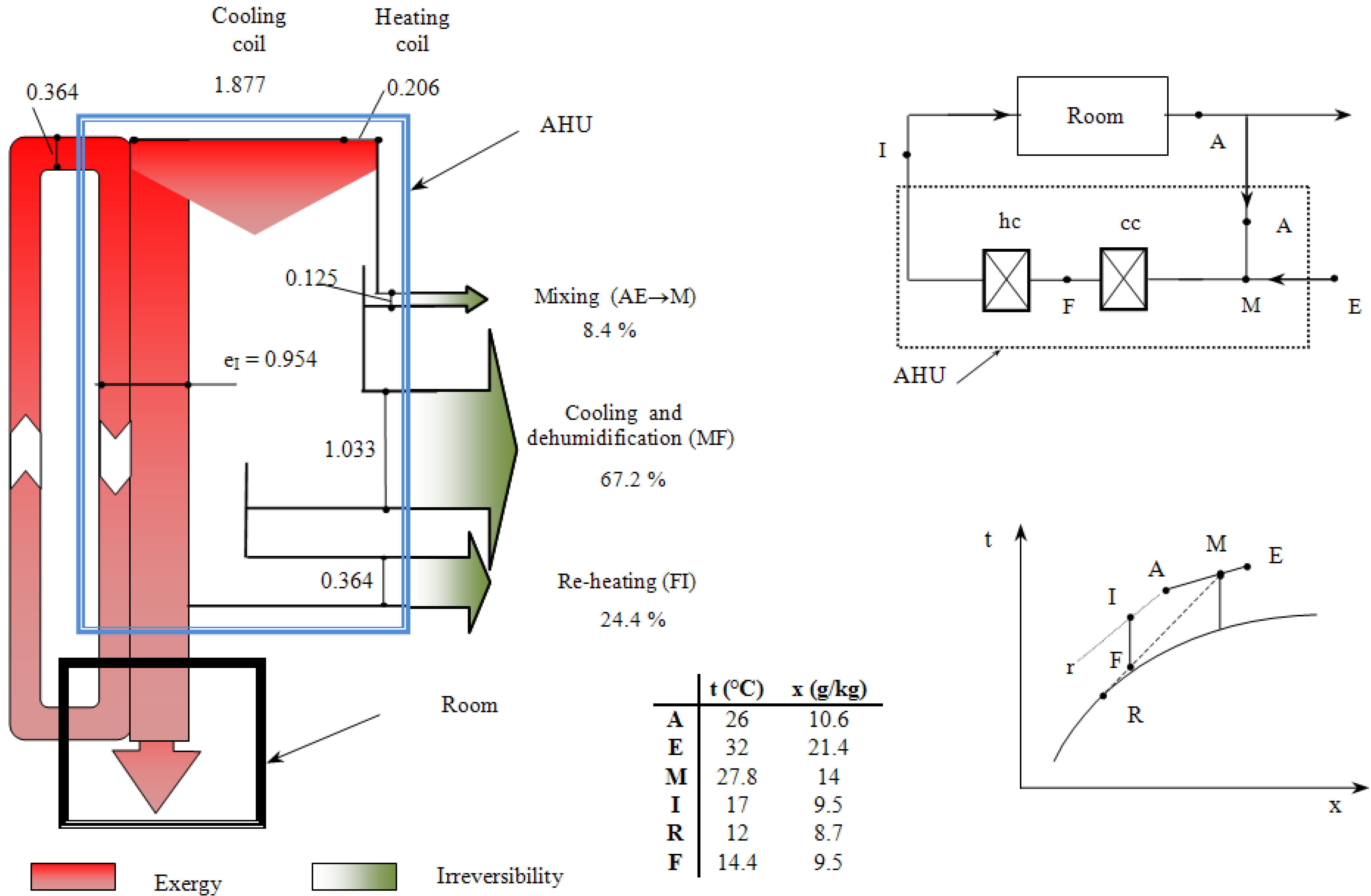
Figure 2.
Dual duct system (Exergy data in kJ/kg of supply air).
Figure 2.
Dual duct system (Exergy data in kJ/kg of supply air).
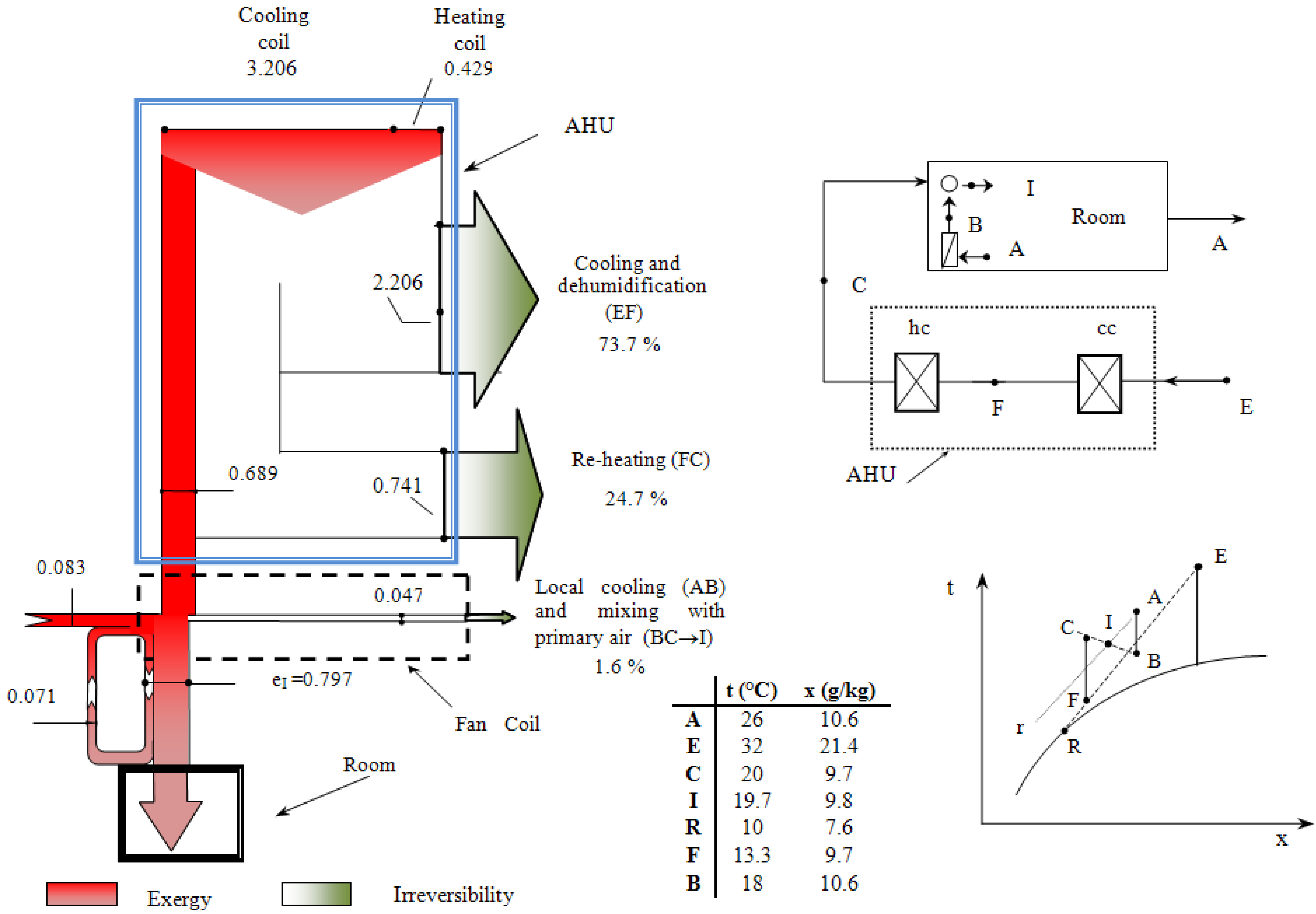
Figure 3.
Fan coil system (Exergy data in kJ/kg of supply air).
Figure 3.
Fan coil system (Exergy data in kJ/kg of supply air).
5. Definition of Exergy Efficiency
A fundamental step in this analysis is the evaluation of the exergy efficiency of various processes and/or components. Now, going through the literature, there is much discussion about the definition of exergy efficiency and namely that one of psychrometric processes. Although all authors agree on the concept that exergy efficiency is the ratio of exergy output to exergy input for any given process, there is not a general agreement on the operative definition of it, see for instance [
5,
6,
7,
8,
9].
To illustrate the various positions, let us consider, for example, the case of the cooling coil for the all-air system. With reference to
Figure 1, it is possible to state the irreversibility production per unit of air mass as:
where
(e1)
cc and
(e2)
cc is the exergy of the supply water at the inlet and outlet section of the cooling coil;
eM and
eF is the exergy of the air stream at M and F read on the psychrometric chart;
ew is the exergy of the condensate. Furthermore:
γ =
mcc/m and‖
δ =
mw/m.
Since the condensate is wasted, the irreversibility for the cooling coil may be assessed as follows:
As to the exergy efficiency, the following definitions are possible:
- (a)
"overall" outlet to "overall" inlet exergy ratio
- (b)
"net" useful product exergy to "net" exergy supply ratio
- (c)
“useful product” exergy to overall exergy supply ratio
Now a short comment follows. Definition a) does not seem suitable because it merges elements of a different nature, such as eF (the actually "useful product" of the process) and γ (e2 )cc (a "by-product").
Definition b) makes a clear distinction between the "net useful product" of the process (numerator) and the "net exergy supply" (denominator). However, difficulties may arise, in the case of the heating coil, where the exergy supply is used not to upgrade the exergy of the air stream but to lower it. Indeed, since both
TF and
TI are lower than the reference temperature
To, the process from F to I (
Figure 1) yields
ζ <
0! This may be an unexpected result, but reveals that the process under consideration is making an irrational use of exergy: indeed the net exergy content of one stream is used not to upgrade but to destroy the exergy level of the other stream.
Statement c) is free from the drawbacks mentioned for definition a), but may not reveal cases affected by thermodynamic irrationality with the same emphasis as does definition b). As a result, definition b) will be preferred in this study.
6. The Second Law Analysis of the AHU
As far as the Air Handling Unit (AHU) is concerned, the results of this analysis can be seen in
Figure 1,
Figure 2 and
Figure 3. Besides the already mentioned conceptual scheme and the thermal cycle in the psychrometric chart, each figure includes the design data and the exergy flow diagram, whereas
Table 3,
Table 4 and
Table 5 report both the irreversibility production and the exergy efficiency. The exergy flow diagrams clearly show that the irreversibility production, in all cases, is first attributable to the cooling and dehumidification process, then to the re-heating process and finally to the mixing of humid air streams.
It can be seen from
Table 1,
Table 2 and
Table 3 , the exergy efficiencies of the AHU for the three cases, assessed after definition b), lay in the range 20 ÷ 30%. The lowest value pertains to the fan coil system, because no recirculation occurs and because treatment of the primary air requires a great deal of energy. The cooling and mixing with primary air, within the room, entails very low irreversibility production because of the low mass flow rate treated by the local fan coil, relative to the primary air.
Table 3.
All‑air system.
Process
(Reference Figure 1) | Exergy efficiency | Irreversibility% |
| Primary air mixing (AE → M) | 65.5% | 8.4% |
| Cooling and dehumidification (MF) | 46.5% | 67.2% |
| Re‑heating (FI) | <0 | 22.4% |
| Air Handling Unit | 28.4% | 100% |
Table 4.
Dual duct system.
Table 4.
Dual duct system.
Process
(Reference Figure 2) | Exergy efficiency | Irreversibility |
| Primary air mixing(AE→M) | 65.5% | 8.9% |
| Cooling and dehumidification (MF) | 50.0% | 61.4% |
| Re‑heating (MC) | < 0 | 12.2% |
| Secondary mixing (FC → I) | 78.1% | 17.5% |
| Air Handling Unit | 26.7% | 100% |
Table 5.
Fan coil system.
Table 5.
Fan coil system.
| Process (Reference Figure 1) | Exergy efficiency | Irreversibility |
| Cooling and dehumidification of primary air (EF) | 31.2% | 73.7% |
| Re‑heating of primary air (FC) | <0 | 24.7% |
| Local cooling of secondary air and mixing with primary air (AB + CB→I) | 93.9% | 1.6% |
| Air Handling Unit | 19.5 % | 100% |
As a general remark, we can say that cooling and dehumidification is a quite exergy expensive process, due to the deviation of the thermodynamic final state of the air stream (F), form the reference state (E), both for temperature and absolute humidity. In general between the two, cooling is more demanding, in terms of exergy, than dehumidifying. Also, there is a by-product wasted to the environment: the condensate, dripping out from the cooling coil.
As outlined above, reheating is indeed a quite irrational process. Besides a great deal of exergy to cool and dehumidify the air stream from M (or E) to F, one uses further exergy to bring the air from a higher to a lower exergy level (from F to I). Of course there is a practical reason for that: from one hand, one has to dehumidify from M to F; from the other hand, it is necessary to supply the air at 15–18 °C, to comply with comfort requirements.
With conventional technologies the problem is currently solved by reheating the air with a water-to-air heat exchanger. However, although that can be a quite practical and cheap solution, it proves to be unsatisfactory from the thermodynamic point of view. For a more appropriate approach, a low grade (or zero) exergy source should be used instead. More appropriate solutions may be using the chiller rejected heat or a heat exchanger between the supply and the outdoor air. Of course these solutions are much more expensive, that is why a reasonable compromise should be sought between energy (exergy!) and economic issues. An approach to this aim is provided by exergonomics. Some applications in the realm of HVAC systems can be seen in [
10,
11,
12].
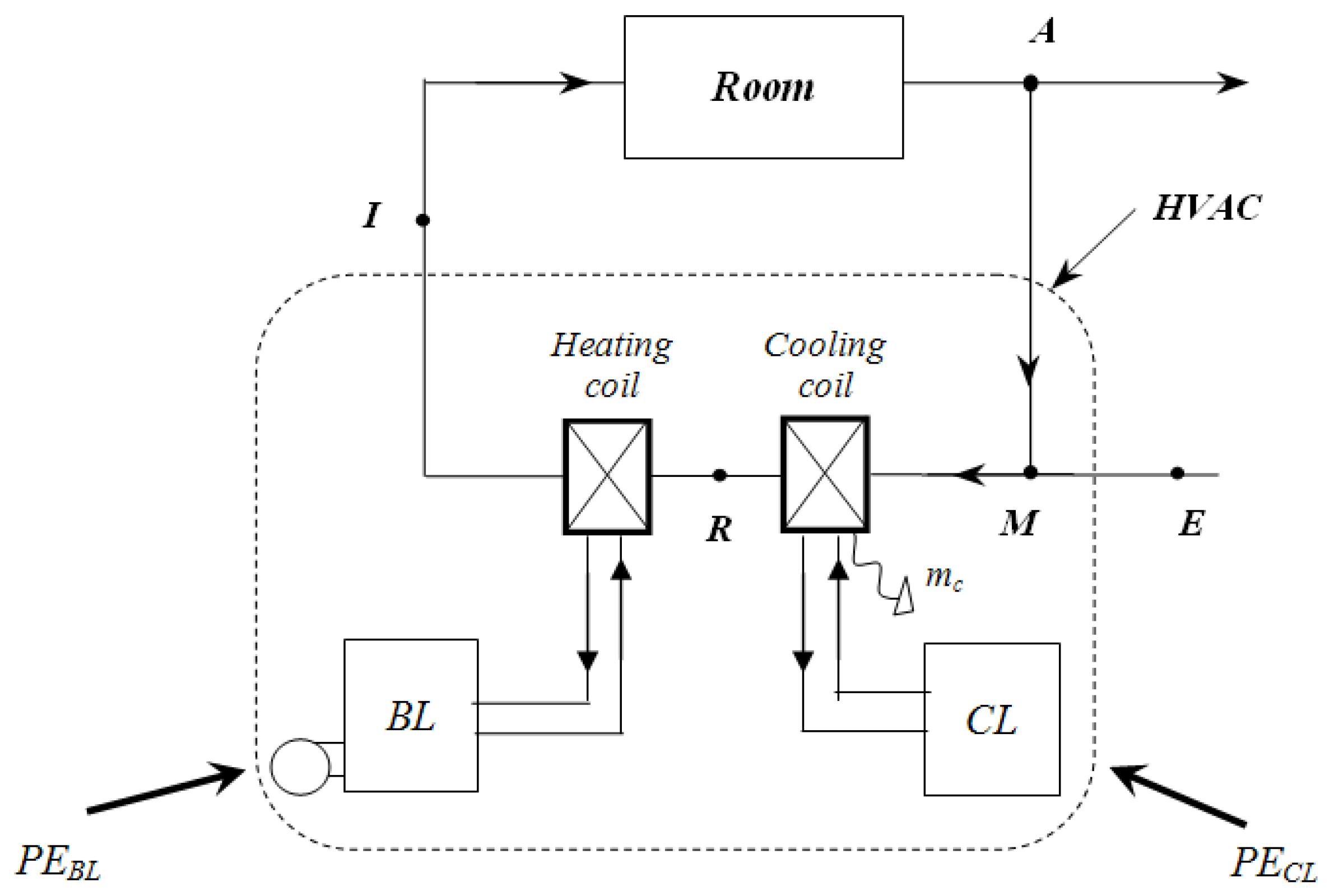
7. Enlarging the Control Volume: Electric and Thermal Power Sources
The exergy analysis of the HVAC can be completed by including what stands behind the AHU, e.g., power technologies (chillers, boilers) and auxiliary equipment (pumps, fans, control devices
etc.). That implies the enlargement of the previous control volume in
Figure 4 to that shown in
Figure 5.
Figure 4.
Control volume for the study of AHU.
Figure 4.
Control volume for the study of AHU.
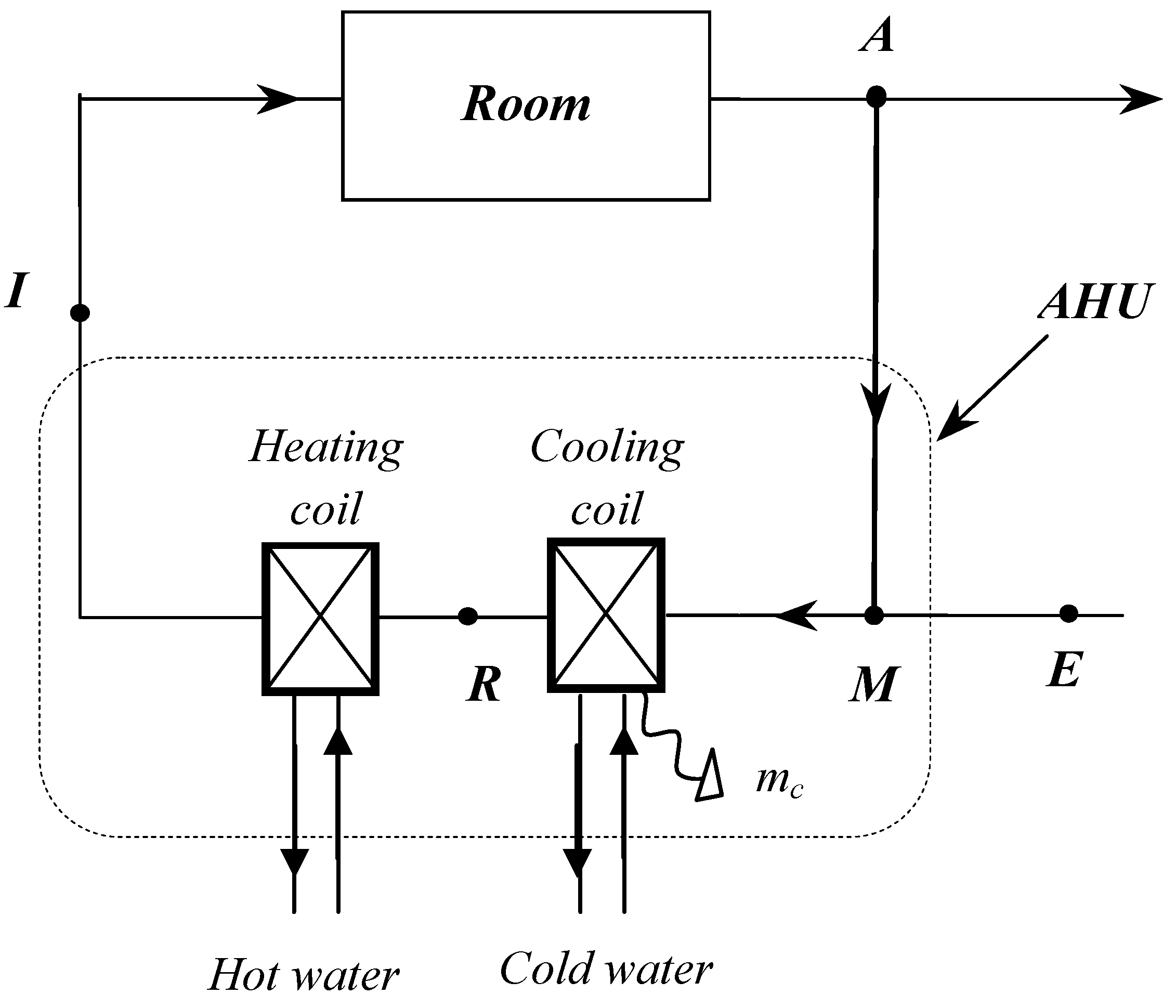
Figure 5.
Control volume for the study of the whole HVAC.
Figure 5.
Control volume for the study of the whole HVAC.
However, in order to give the most complete picture of HVAC technologies from the point of view of the energy use, we must also account for the primary energy sources.
To this aim, let
ηBL be the energy efficiency of the boiler and
COP the coefficient of performance of the chiller. Thus the Primary Energy (PE) required to drive the boiler and the chiller respectively is:
being
QBL the thermal load of the heating coil and
ηel the efficiency of the electric system assessed at national level (for EU
ηel = 0.4).
Now for the evaluation of the exergy content (E
s) of the PE, either of the following expressions may be used:
The rationale of equations (a) or (b) is that the exergy content for a PE source may be linked either to the Carnot Factor associated with the flame temperature
Tf occurring in the furnace (being
Tf the highest temperature of the system and, as such, representative of its highest thermodynamic potential); or to a corrective factor
ψ, defined as the fuel availability to the lower heating value (
Hi) ratio. Such a datum is reported in the literature [
7,
13,
14] and very close to unity for the most common fuels.
In case of lack of data, the following approximation may be adopted:
being
Hs/Hi the higher to the lower heating value ratio.
Please note that in any case, for the evaluation of ψ, reference is made to what is actually burnt in the furnace. So in practice, for a boiler fed with natural gas ψBL = (Hs/Hi)BL ≅ 1.1 and for central power stations, based on a nationwide mix of fuels, where oil is dominant, we should use ψCL = (Hs/Hi)CL ≅ 1.06.
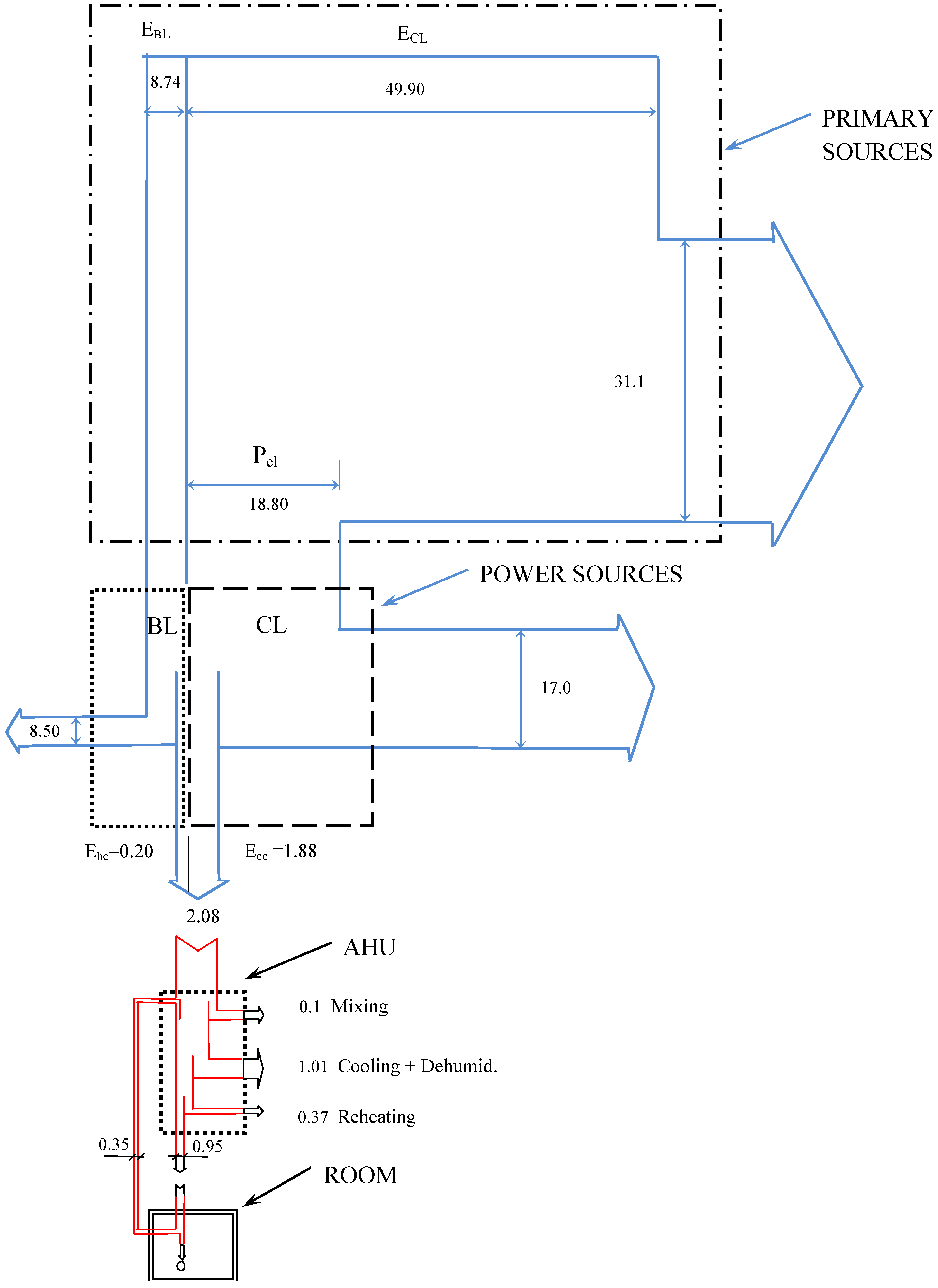
Figure 6.
Exergy flows for the whole HVAC (data in kJ/kg of supply air).
Figure 6.
Exergy flows for the whole HVAC (data in kJ/kg of supply air).
Actually the use of equation (a), affected by the flame temperature, is more instructive because it makes the designer aware of the distance between the energy potential of the primary source and that of the final use, as proportional to the distance in temperatures; as such, it can be recommended in the educational context. On the other hand, it implies assumptions on the flame temperature. Instead, the assessment of the (Hs/Hi) ratio may allow higher precision, on the basis of tabular data for the given fuel or mix of fuels. That‘s why, in the following, the latter approach will be used.
8. The Results
With reference to the most relevant design data collected in
Table 6 and on the basis of the approach outlined above, it is possible to carry out the exergy analysis of the whole system, from the PE sources down to AHU, via the power sources. The HVAC considered in this analysis is the all-air system. The results are reported in
Figure 6, where they appear as an exergy flow diagram.
Table 6.
Relevant design data for the all-air system.
Table 6.
Relevant design data for the all-air system.
| Building thermal load | 10.2 kW |
| Thermal power for the heating coil | 5.3 kW |
| Cooling power for the cooling coil | 52.6 kW |
| Chiller COP | 2.8 |
| Boiler efficiency | 90% |
| Efficiency of the national electric system | 40% |
| Hs/Hi for electricity | 1.06 |
| Hs/Hi for the boiler | 1.1 |
The picture allows the detection of four blocks: Primary Sources, Power Sources, AHU and the Room. Each block is connected to the other by one or more exergy flows. The numerical values represent the exergy content of each flow in kJ/kg of supply air. It is understood that flows directed downwards represent the exergy allowed from one block to the other, whereas flows directed rightwards represent the exergy loss due to the irreversibility production occurring in the block. By using the reported values it is easy to calculate the exergy efficiency for each section. The results are summarized in
Table 7.
Table 7.
Exergy efficiency of the main processes for the HVAC, (°) Numerical values taken from
Figure 6.
Table 7.
Exergy efficiency of the main processes for the HVAC, (°) Numerical values taken from Figure 6.
| | Calculations (°) | Exergy efficiency |
|---|
| Primary Sources | (18.80 + 8.74) / ( 49.90 + 8.74) = | 46.9% |
| Power Sources | 2.08 / (18.80 + 8.74) = | 7.6% |
| AHU | (0.95 – 0.35) / 2.08 = | 28.8% |
| Overall System | (0.95 – 0.35) / (49.9 + 8.74) = | 1.0% |
The messages arising from this analysis are several. First of all, each passage from one block to the other reduces heavily the exergy content of the incoming flow. That implies a large distance between the theoretical minimum exergy to achieve a given end-use and the exergy level we are using to perform the process with technical means. This can be understood for example by comparing the exergy offered by the boiler (EBL = 8.74 kW) to that found in the hot water stream (Ew = 8.74 – 8.50 = 0.24 kW), which parallels the distance between the boiler flame temperature (1,300 °C) and that required to produce hot water (60 °C), not to mention the final air stream re-heating temperature (TI = 16 °C).
Furthermore, the extremely low exergy efficiency of the system as a whole (1.0%), tells us about the improper use we make of the energy sources. Look also at the picture of the exergy flows across the whole system: it gives a dramatic perception of the huge amount of the energy potential (exergy) exploited to produce a stream of fresh air.
The picture also shows that, in order to save exergy, it is important to use electricity as little as possible. Electricity is indeed pure exergy and its use should be limited to drive the electric equipment (pumps, fans, control devices etc.). Thus a technology should be sought for cooling and dehumidification other than the electric chiller.
In conclusion, the messages arising from this analysis can be summarized as follows:
For each process, adopt an energy potential as close as possible to that strictly required by the end-use.
Avoid any unnecessary use of electricity (i.e., try to find substitutes for the chiller).
Find a convenient way to use renewable energy for air conditioning.
9. The Future of Air-Conditioning: Solar Cooling
Currently, one of the most promising answers to the previous key-points comes from thermally driven cooling technologies, where solar energy can be used as a heat source. Today, most of the installations of this kind are provided with absorption machines in closed cycle arrangement, while much less widespread are the solar cooling systems based on adsorption chillers. In the most recent times, a great interest is being devoted to the open-cycle systems based on desiccant materials due to the ability of producing conditioned air in a direct way, i.e., without preliminary production of chilled water. Desiccants may be of liquid or solid type, but in general it is possible to use solar energy for regenerating the sorbent.
Actually, most promising are those desiccant systems based on solid sorbents, (silica gel, metal silicate or synthetic zeolite) arranged in rotating desiccant wheels (DW). From the energy savings point of view, a very effective design can be achieved by combining in a proper way one DW, a gas-to-gas heat exchanger (HX) and one or two evaporative coolers (EC) [
15,
16,
17,
18]. Apart electricity-driven equipment (pumps, fans, control devices), the system can be totally powered by solar energy (solar DEC).
In reality, the exergy efficiency (and energy savings) of a solar DEC depends also on the solar fraction (F
s),
i.e., the fraction of the heating load for regeneration covered by solar. An analysis, carried out for a solar DEC, in operative conditions close to the ones considered in this paper, shows that the exergy efficiency rises sharply with F
s [
19]. That has a clear meaning: solar energy, with its relatively low energy potential—when made available by a low-to-medium temperature collector-, is much closer than the conventional power sources to the exergy levels required by the final uses in this field of applications:
i.e., heating fluids at moderate temperatures. As such, it represents a more appropriate energy source to air-conditioning than conventional chillers and boilers.
The study also shows the pathways to even better thermodynamic performance of solar-cooling systems, such as: 1) reducing the regeneration temperature, achievable through R&D activity on the materials (this would also permit flat plate solar collectors, instead of focusing collectors, with great economical benefit); 2) using enthalpy wheels, with important simplification in the design of the whole system.
The interpretation of these new technologies in terms of exergy will be dealt with in a future paper. Here it is important to outline some critical points related to the solar cooling technologies, such as the energy investment for the production of the solar components (embodied energy), parasitic consumption (for the air flow across desiccant wheel, heat recovery systems, dampers etc.), hot and/or cold storage , etc., not to mention the still high investment costs.
Nevertheless, is high the interest of the scientific community to these topics: it is worth mentioning the SACE Project (Solar Air conditioning in Europe), launched in 2002, sustained by five EU countries and aimed to assess state-of-the-art, future needs and overall prospects of solar cooling in the European Union [24]. More recently this topic deserved the attention of the International Energy Agency (IEA) with Task 25 (2002–2005) and Task 38 (2006–2010), which now gather 55 research groups and 13 Countries [25].
10. Conclusions
The 2nd law analysis outlined above reveals the poor performance of the most common air-conditioning system plant schemes. Most responsible for the production of irreversibility within a conventional air-handling unit is the cooling and dehumidification process, but also the reheating (although necessary to fulfill the comfort requirements) is very irrational from the thermodynamic point of view because it uses exergy to destroy exergy. The exergy efficiency proves to be low for the AHU as a whole and even lower, up to a few percent, when the power sources are taken into account.
The use of electricity to drive the compression chiller—with its very high exergy content—and the use of boilers to perform reheating—with a flame temperature much higher than that required by the supply air—are the proofs of the disproportion between the theoretically minimum and the exergy level actually used to perform a given process. In practical terms, it is the mark of the improper use we make of energy sources in this field, with the current technologies.
The second law analysis has indicated the most promising directions to follow. Chemical dehumidification combined with solar energy into the solar cooling technology seems to be very interesting. At the present it is actively pursued by the scientific community, although a lot of R&D must be done before a large scale application.


 the efficiency of the electric system (nationwide efficiency) and
  the efficiency of the boiler driving the sorption chiller. Rough numbers may be as follows: ηel = 0.40 (recommended value for Europe); ηg = 0.90, thus: PERel = (2 ÷ 4) · 0.4 = 0.8 ÷ 1.6 and PERth = (0.7 ÷ 1.2) · 0.9 = 0.63 ÷ 1.08.

 is the exergy of a flowing stream of matter, the term To σ represents the irreversibility, and To a reference temperature.
 , cpa and cpv are the specific heat for the dry air and water vapour respectively, whereas Ra is the gas constant for the dry air. The ea is evaluated on a dry air mass basis (kJ/kg of dry air).
  , thus ea = e(T,x).
