Light-Emitting Porphyrin Derivative Obtained from a Subproduct of the Cashew Nut Shell Liquid: A Promising Material for OLED Applications

 , ,
, ,  ,
,
Abstract
:1. Introduction
2. Materials and Methods
2.1. General
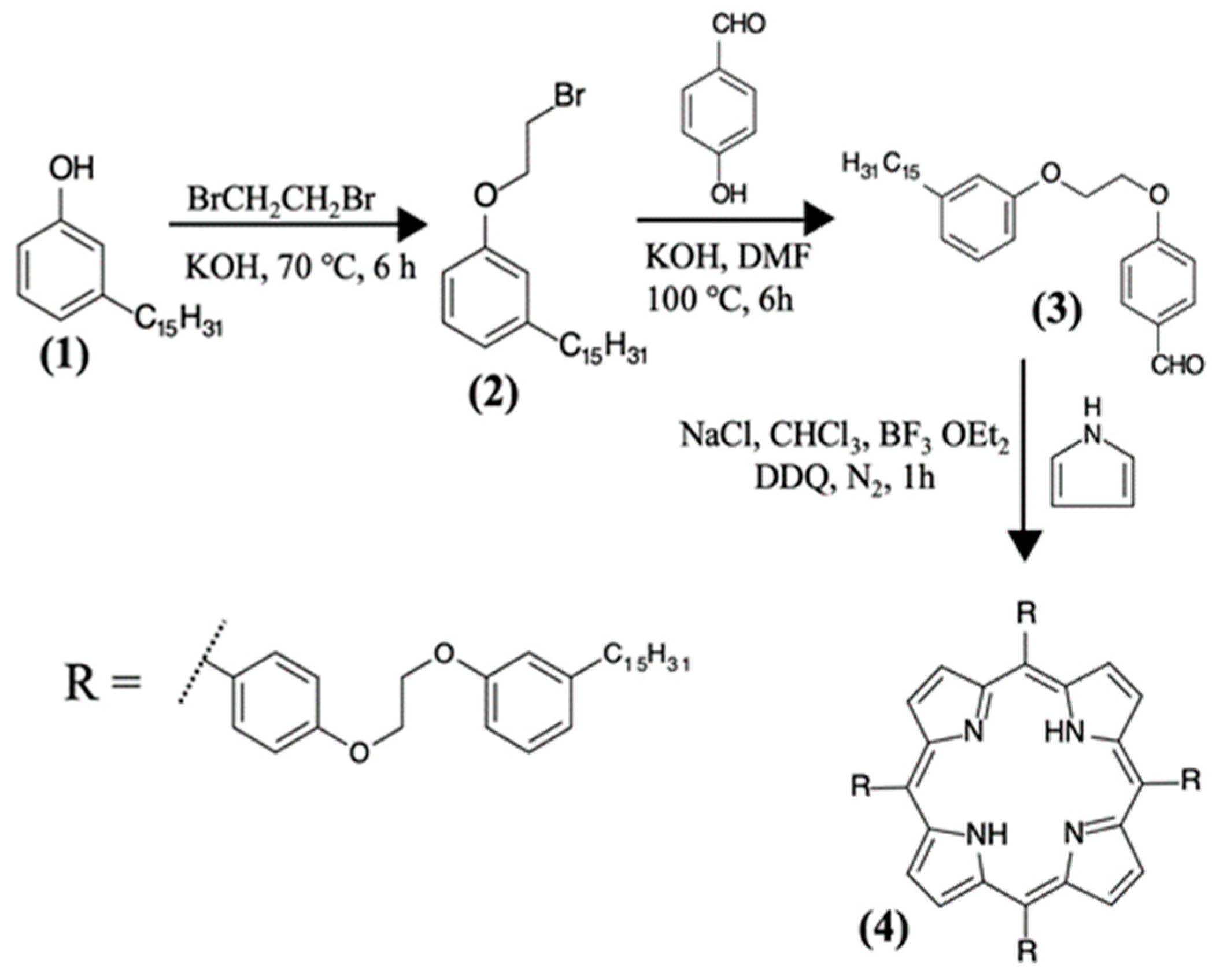
2.2. Synthesis of the H2P, ZnP, and CuP porphyrins from Cardanol
2.3. Fabrication and Characterization of the OLEDs
3. Results and Discussion
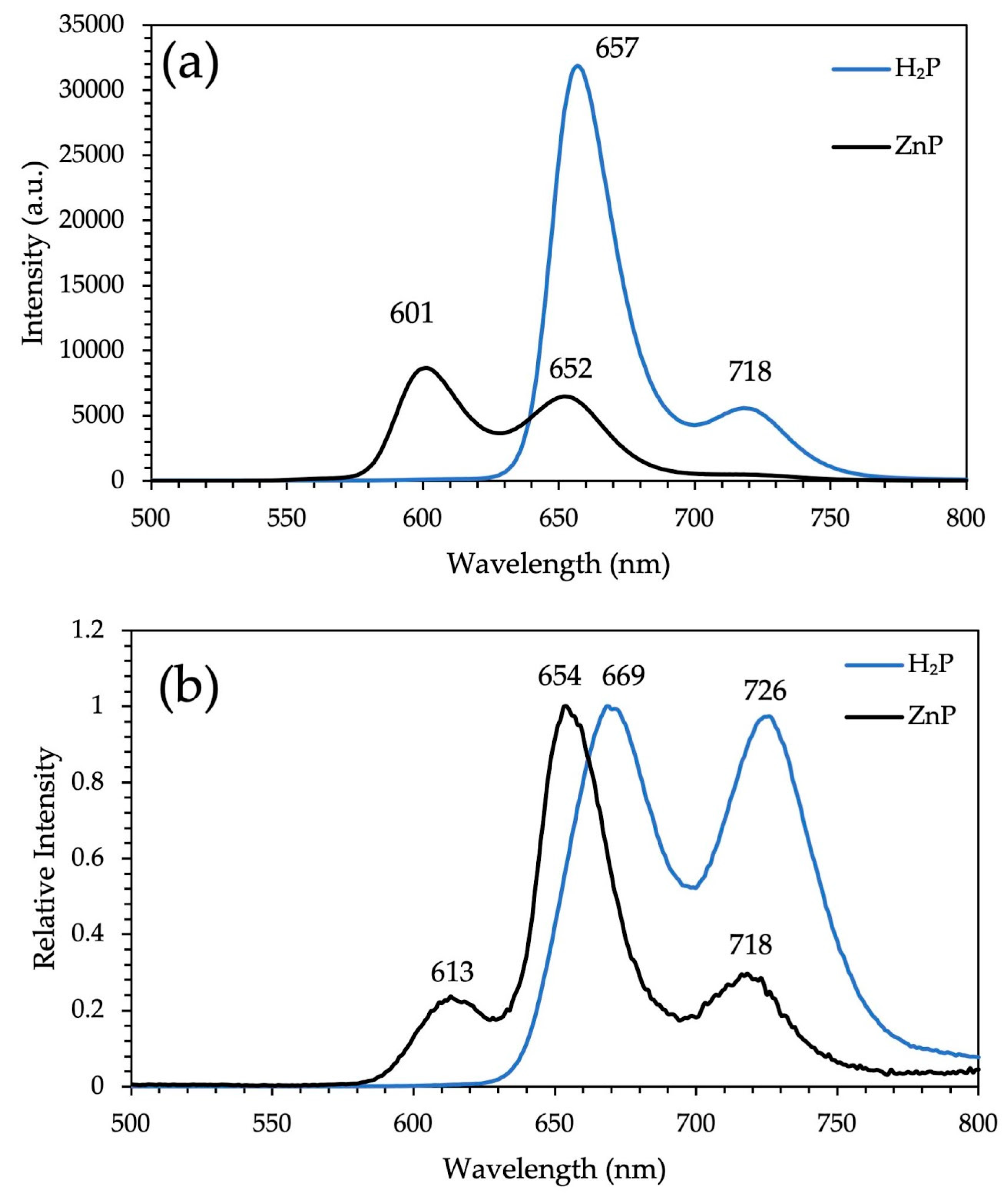
3.1. XRD Analysis, Absorption, and Photoluminescence Properties
3.2. Electrochemical Properties
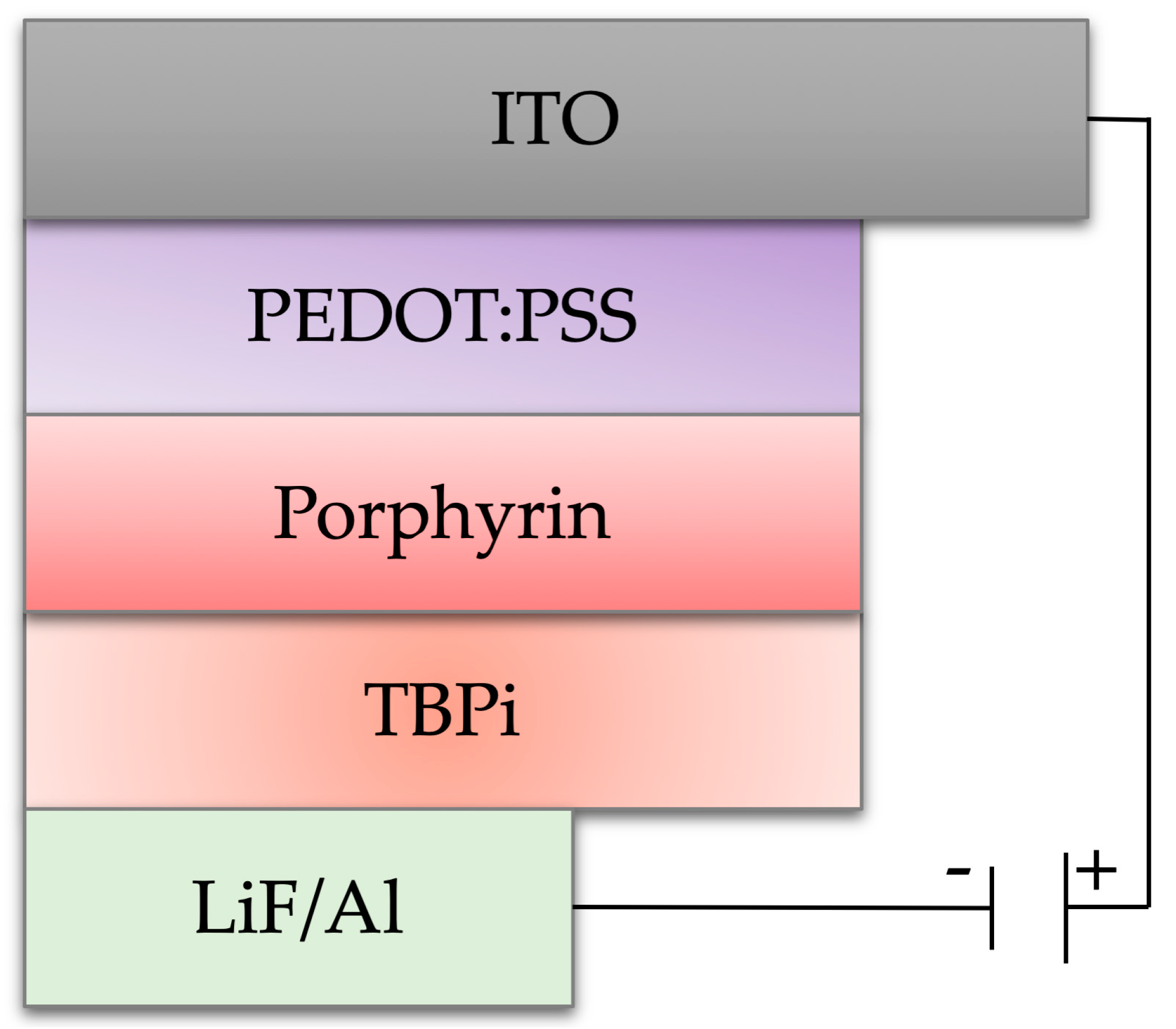
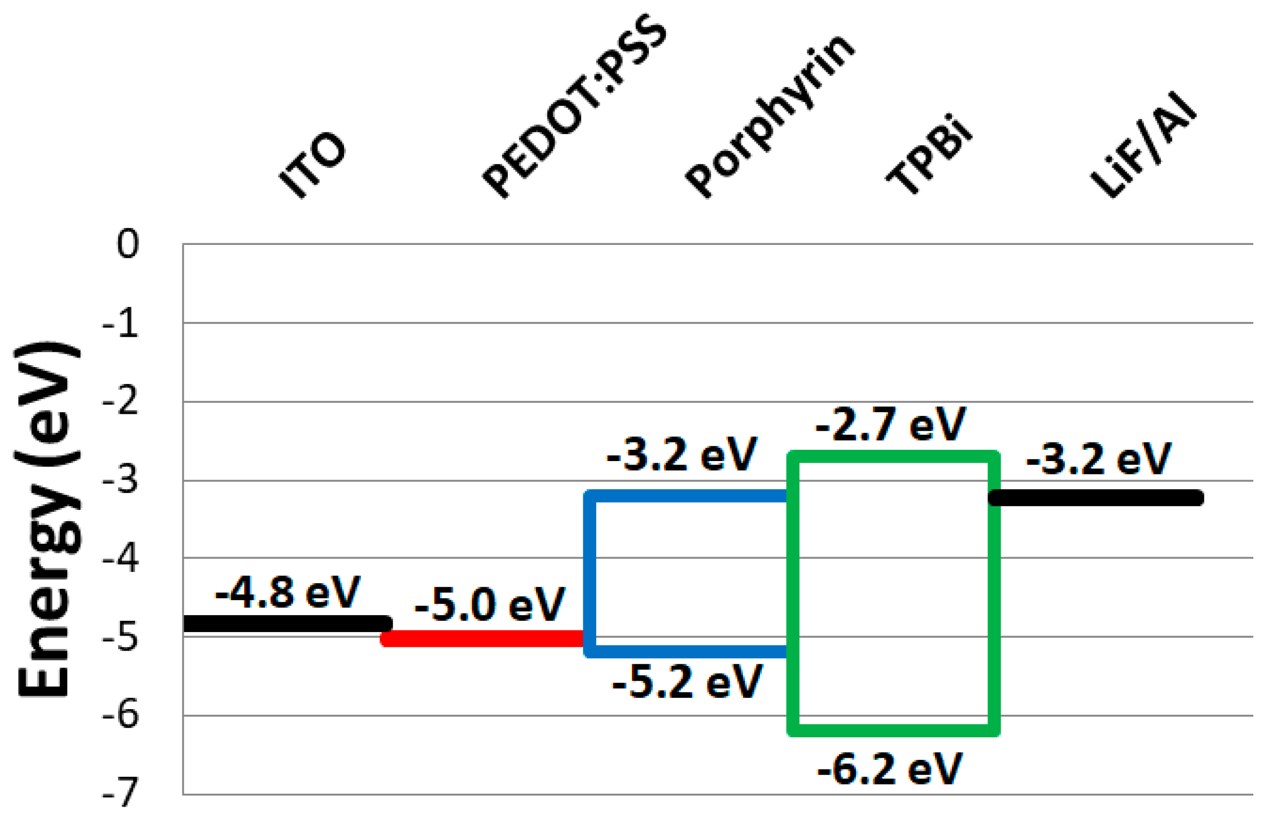
3.3. Fabrication of the OLEDs Ddevices
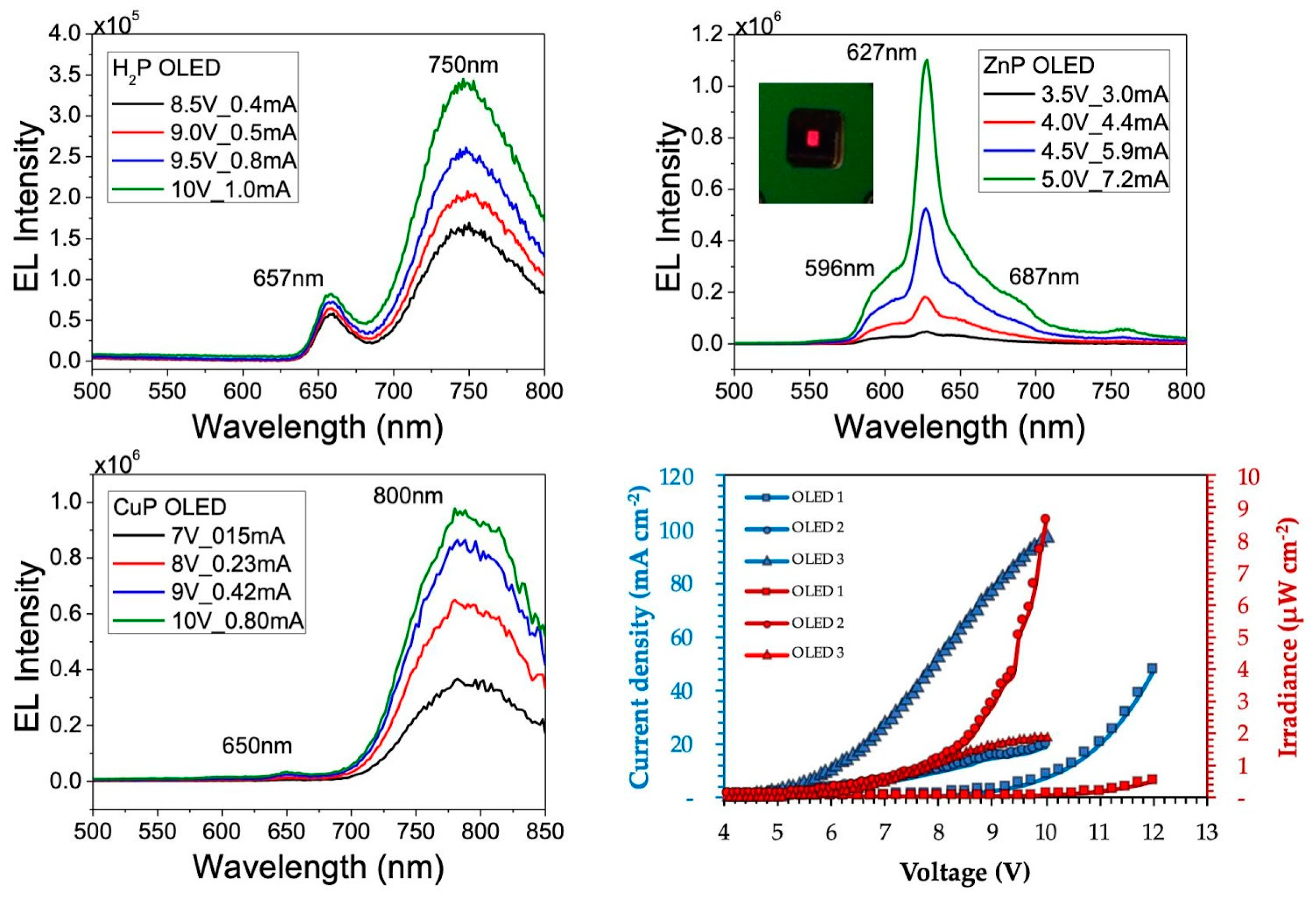
3.4. Electroluminescence (EL)
4. Conclusions
Supplementary Materials
Author Contributions
Funding
Acknowledgments
Conflicts of Interest
References
- Giovanella, U.; Pasini, M.; Botta, C. Organic Light-Emitting Diodes (OLEDs): working principles and device technology. In Applied Photochemistry, 1st ed.; Bergamini, G., Silvi, S., Eds.; Springer: Cham, Switzerland, 2016; pp. 145–196. ISBN 978-3-319-31669-7. [Google Scholar]
- Graham, K.R.; Yang, Y.; Sommer, J.R.; Shelton, A.H.; Schanze, K.S.; Xue, J.; Reynolds, J.R. Extended Conjugation Platinum(II) Porphyrins for use in Near-Infrared Emitting Organic Light Emitting Diodes. Chem. Mater. 2011, 23, 5305–5312. [Google Scholar] [CrossRef]
- Vasilopoulou, M.; Georgiadou, D.G.; Soultati, A.; Douvas, A.M.; Papadimitropoulos, G.; Davazoglou, D.; Pistolis, G.; Stathopoulos, N.A.; Kamalakis, T.; Alexandropoulos, D.; et al. Solution processed multi-color organic light emitting diodes for application in telecommunications. Microelectron Eng. 2015, 145, 21–28. [Google Scholar] [CrossRef]
- Wang, J.; Zhang, F.; Zhang, J.; Tang, W.; Tang, A.; Peng, H.; Xu, Z.; Teng, F.; Wang, Y. Key issues and recent progress of high efficient organic light-emitting diodes. J. Photochem. Photobiol. C 2013, 17, 69–104. [Google Scholar] [CrossRef]
- Volz, D.; Wallesch, M.; Fléchon, C.; Danz, M.; Verma, A.; Navarro, J.M.; Zink, D.M.; Bräse, S.; Baumann, T. From iridium and platinum to copper and carbon: new avenues for more sustainability in organic light-emitting diodes. Green Chem. 2015, 17, 1988–2011. [Google Scholar] [CrossRef]
- Quirino, W.G.; Teixeira, K.C.; Legnani, C.; Calil, V.L.; Messer, B.; Vilela Neto, O.P.; Pacheco, M.A.C.; Cremona, M. Improved multilayer OLED architecture using evolutionary genetic algorithm. Thin Solid Films 2009, 518, 1382–1385. [Google Scholar] [CrossRef]
- Bagatin, I.A.; Legnani, C.; Cremona, M. Investigation on Al(III) and Zn(II) complexes containing a calix [4] arene bearing two 8-oxyquinoline pendant arms used as emitting materials for OLEDs. Mater. Sci. Eng. C 2009, 29, 267–270. [Google Scholar] [CrossRef]
- Roth, C.O.P.; Drouet, S.; Merhi, A.; Williams, J.A.G.; Gildea, L.F.; Pearson, C.; Petty, M.C. Synthesis of platinum complexes of fluorenyl-substituted porphyrins used as phosphorescent dyes for solution-processed organic light-emitting devices. Tetrahedron 2013, 69, 9625–9632. [Google Scholar] [CrossRef] [Green Version]
- Janghouri, M.; Adineh, M. Color optimization of red organic light emitting diodes (OLEDs) through dihydroxyphenyl-substituted zinc porphyrins emitters. J. Photochem. Photobiol. A 2017, 341, 31–38. [Google Scholar] [CrossRef]
- Barrientos, H.; Arias, E.; Moggio, I.; Romero, J.; Rodriguez, O.; Giorgetti, E.; Del Rosso, T. Dodecanoxy-phenylethynylene oligomers for light emitting diodes. Synth. Met. 2004, 147, 267–270. [Google Scholar] [CrossRef]
- Shan, T.; Gao, Z.; Tang, X.; He, X.; Gao, Y.; Li, J.; Sun, X.; Liu, Y.; Liu, H.; Yang, B.; et al. Highly efficient and stable pure blue nondoped organic light-emitting diodes at high luminance based on phenanthroimidazole-pyrene derivative enabled by triplet-triplet annihilation. Dyes Pigm. 2017, 142, 189–197. [Google Scholar] [CrossRef]
- Gudeika, D.; Volyniuk, D.; Mimaite, V.; Lytvyn, R.; Butkute, R.; Bezvikonnyi, O.; Buika, G.; Grazulevicius, J.V. Carbazolyl-substituted quinazolinones as high-triplet-energy materials for phosphorescent organic light emitting diodes. Dyes Pigm. 2017, 142, 394–405. [Google Scholar] [CrossRef]
- Wang, P.; Fan, S.; Liang, J.; Ying, L.; You, J.; Wang, S.; Li, X. Carbazole-diphenylimidazole based bipolar material and its application in blue, green and red single layer OLEDs by solution processing. Dyes Pigm. 2017, 142, 175–182. [Google Scholar] [CrossRef]
- Jafari, M.R.; Bahrami, B. Emission properties of porphyrin compounds in new polymeric PS: CBP host. Appl. Phys. A 2015, 119, 1491–1497. [Google Scholar] [CrossRef]
- Shahroosvand, H.; Zakavi, S.; Sousaraei, A.; Mohajeranic, E.; Mahmoudic, M. Unusual near-white electroluminescence of light emitting diodes based on saddle-shaped porphyrins. Dalton Trans. 2015, 44, 8364–8368. [Google Scholar] [CrossRef] [PubMed]
- Lomonaco, D.; Mele, G.; Mazzetto, S.E. Cashew Nutshell Liquid (CNSL): from an agro-industrial waste to a sustainable alternative to petrochemical resources. In Cashew Nut Shell Liquid: A Goldfield for Functional Materials, 1st ed.; Anilkumar, P., Ed.; Springer: Cham, Switzerland, 2017; pp. 19–38. ISBN 978-3-319-47455-7. [Google Scholar]
- Mele, G.; Lomonaco, D.; Mazzetto, S.E. Cardanol-based heterocycles: synthesis and applications. In Cashew Nut Shell Liquid; Anilkumar, P., Ed.; Springer: Cham, Switzerland, 2017; pp. 39–56. ISBN 978-3-319-47455-7. [Google Scholar]
- Ribeiro, V.G.P.; Marcelo, A.M.P.; Silva, K.T.; Silva, F.L.F.; Mota, J.P.F.; Nascimento, J.P.C.; Sombra, A.S.B.; Clemente, C.S.; Mele, G.; Carbone, L.; et al. New ZnO@Cardanol Porphyrin Composite Nanomaterials with Enhanced Photocatalytic Capability under Solar Light Irradiation. Materials 2017, 10, 1114. [Google Scholar] [CrossRef] [PubMed]
- Vasapollo, G.; Mele, G.; del Sole, R.; Pio, I.; Li, J.; Mazzetto, S.E. Use of Novel Cardanol-Porphyrin Hybrids and Their TiO2-Based Composites for the Photodegradation of 4-Nitrophenol in Water. Molecules 2011, 16, 5769–5784. [Google Scholar] [CrossRef] [PubMed]
- Attanasi, O.A.; Berretta, S.; Fiani, C.; Filippone, P.; Mele, G.; Saladino, R. Synthesis and reactions of nitro derivatives of hydrogenated cardanol. Tetrahedron 2006, 62, 6113–6120. [Google Scholar] [CrossRef]
- Mota, J.P.F.; Júnior, A.E.C.; Ribeiro, V.G.P.; Sampaio, S.G.; Lima, N.M.A.; Silva, F.L.F.; Clemente, C.S.; Mele, G.; Lomonaco, D.; Mazzetto, S.E. Synthesis, Characterization and Dielectric Properties of New 5-(4-Hydroxyphenyl)-10,15,20-tri-4-[2-(3-pentadecylphenoxy)ethoxy] phenyl porphyrin and Their Ni, Co and Cu Complexes. J. Braz. Chem. Soc. 2016, 28, 1063–1073. [Google Scholar] [CrossRef]
- Voirin, C.; Caillol, S.; Sadavarte, N.V.; Tawade, B.V.; Boutevin, B.; Wadgaonkar, P.P. Functionalization of cardanol: towards biobasedpolymers and additives. Polym. Chem. 2014, 5, 3142–3162. [Google Scholar] [CrossRef]
- Clemente, C.S.; Ribeiro, V.G.P.; Sousa, J.E.A.; Maia, F.J.N.; Barreto, A.C.H.; Andrade, N.F.; Denardin, J.C.; Mele, G.; Carbone, L.; Mazzetto, S.E.; et al. Porphyrin synthesized from cashew nut shell liquid as part of a novel superparamagnetic fluorescence nanosystem. J Nanopart Res. 2013, 15, 1739–1749. [Google Scholar] [CrossRef]
- Deyab, M.A.; Mele, G.; Al-Sabagh, A.M.; Bloise, E.; Lomonaco, D.; Mazzetto, S.E.; Clemente, C.D.S. Synthesis and characteristics of alkyd resin/M-Porphyrins nanocomposite for corrosion protection application. Prog. Org. Coat. 2017, 105, 286–290. [Google Scholar] [CrossRef]
- Sandrino, B.; Clemente, C.D.S.; Oliveira, T.M.B.F.; Ribeiro, F.W.P.; Pavinatto, F.J.; Mazzetto, S.E.; Neto, P.L.; Correia, A.N.; Pessoa, C.A.; Wohnrath, K. Amphiphilic porphyrin-cardanol derivatives in Langmuir and Langmuir–Blodgett films applied for sensing. Colloids Surf. A 2013, 425, 68–75. [Google Scholar] [CrossRef]
- Bloise, E.; Carbone, L.; Colafemmina, G.; D’Accolti, L.; Mazzetto, S.E.; Vasapollo, G.; Mele, G. First Example of a Lipophilic Porphyrin-Cardanol Hybrid Embedded in a Cardanol-Based Micellar Nanodispersion. Molecules 2012, 17, 12252–12261. [Google Scholar] [CrossRef] [PubMed] [Green Version]
- Attanasi, O.A.; del Sole, R.; Filipponea, P.; Mazzetto, S.E.; Mele, G.; Vasapollo, G. Synthesis of novel lipophilic porphyrin-cardanol derivatives. J. Porphyrins Phthalocyanines 2004, 8, 1276–1284. [Google Scholar] [CrossRef]
- Valicsek, Z.; Horváth, O. Application of the electronic spectra of porphyrins for analytical purposes: The effects of metal ions and structural distortions. Microchem. J. 2013, 107, 47–62. [Google Scholar] [CrossRef] [Green Version]
- Xu, Z.; Mei, Q.; Hua, Q.; Tian, R.; Weng, J.; Shi, Y.; Huang, W. Synthesis, characterization, energy transfer and photophysical properties of ethynyl bridge linked porphyrin–naphthalimide pentamer and its metal complexes. J. Mol. Struct. 2015, 1094, 1–8. [Google Scholar] [CrossRef]
- Kumar, P.R.; Mothi, E.M.; Ramesh, M.; Kathiravan, A. Zn Porphyrin propped with hydantoin anchor: synthesis, photophysics and electron injection/recombination dynamics. Phys. Chem. Chem. Phys. 2018, 20, 5117–5127. [Google Scholar] [CrossRef]
- Verma, S.; Ghosh, H.N. Exciton Energy and Charge Transfer in Porphyrin Aggregate/Semiconductor (TiO2) Composites. J. Phys. Chem. Lett. 2012, 3, 1877–1884. [Google Scholar] [CrossRef] [PubMed]
- Zhang, G.; Chen, Q.; Zhang, Y.; Kong, L.; Tao, X.; Lu, H.; Tian, Y.; Yang, J. Bulky group functionalized porphyrin and its Zn (II) complex with high emission in aggregation. Inorg. Chem. Commun. 2014, 46, 85–88. [Google Scholar] [CrossRef]
- Hong, Y.; Lam, J.W.Y.; Tang, B.Z. Aggregation-induced emission. Chem. Soc. Rev. 2011, 40, 5361–5388. [Google Scholar] [CrossRef] [PubMed]
- Jana, A.; McKenzie, L.; Wragg, A.B.; Ishida, M.; Hill, J.P.; Weinstein, J.A.; Baggaley, E.; Ward, M.D. Porphyrin/platinum(II) C^N^N acetylide complexes: synthesis, photophysical properties, and singlet oxygen generation. Chem. Eur. J. 2016, 22, 4164–4174. [Google Scholar] [CrossRef] [PubMed]
- Xu, X.D.; Zhang, J.; Chen, L.J.; Guo, R.; Wang, D.X.; Yang, H.B. Design and synthesis of branched platinum–acetylide complexes possessing a porphyrin core and their self-assembly behaviour. Chem. Commun. 2012, 48, 11223–11225. [Google Scholar] [CrossRef] [PubMed]
- Fushimi, Y.; Koinuma, M.; Yasuda, Y.; Nomura, K.; Asano, M.S. Effects of end-groups on photophysical properties of poly(9,9-di-n-octylfluorene-2,7-vinylene)s linked with metalloporphyrins: synthesis and time-resolved fluorescence spectroscopy. Macromolecules 2017, 50, 1803–1814. [Google Scholar] [CrossRef]
- Szintay, G.; Horva’th, A. Five-coordinate complex formation and luminescence quenching study of copper(II) porphyrins. Inorg. Chim. Acta 2001, 324, 278–285. [Google Scholar] [CrossRef]
- Milot, R.L.; Moore, G.F.; Crabtree, R.H.; Brudvig, G.W.; Schmuttenmaer, C.A. Electron injection dynamics from photoexcited porphyrin dyes into SnO2 and TiO2 nanoparticles. J. Phys. Chem. C 2013, 117, 21662–21670. [Google Scholar] [CrossRef]
- Verma, S.; Ghosh, A.; Das, A.; Ghosh, H.N. Ultrafast exciton dynamics of J- and H-Aggregates of the porphyrin-catechol in aqueous solution. J. Phys. Chem. B 2010, 114, 8327–8334. [Google Scholar] [CrossRef]
- Ranjith, K.; Swathi, S.K.; Kumar, P.; Ramamurthy, P.C. Dithienylcyclopentadienone derivative-co-benzothiadiazole: An alternating copolymer for organic photovoltaics. Sol. Energy Mater. Sol. Cells 2012, 98, 448–454. [Google Scholar] [CrossRef]
- Stute, S.; Götzke, L.; Meyer, D.; Merroun, M.L.; Rapta, P.; Kataeva, O.; Seichter, W.; Gloe, K.; Dunsch, L.; Gloe, K. Molecular Structure, UV/Vis Spectra, and Cyclic Voltammograms of Mn(II), Co(II), and Zn(II) 5,10,15,20-Tetraphenyl-21-oxaporphyrins. Inorg. Chem. 2013, 52, 1515–1524. [Google Scholar] [CrossRef]
- Nasri, S.; Zahou, I.; Turowska-Tyrk, I.; Roisnel, T.; Loiseau, F.; Saint-Amant, E.; Nasri, H. Synthesis, electronic spectroscopy, cyclic voltammetry, photophysics, electrical properties and X-ray molecular structures of meso -{Tetrakis[4-(benzoyloxy)phenyl]porphyrinato}zinc(II) complexes with aza ligands. Eur. J. Inorg. Chem. 2016, 31, 5004–5019. [Google Scholar] [CrossRef]
- Zerner, M.; Gouterman, M. Porphyrins - IV. Extended Hückel calculations on transition metal complexes. Theor. Chim. Acta 1966, 4, 44–63. [Google Scholar] [CrossRef]
- Li, J.; Nomura, H.; Miyazaki, H.; Adachi, C. Highly efficient exciplex organic light-emitting diodes incorporating a heptazine derivative as an electron acceptor. Chem. Commun. 2014, 50, 6174–6176. [Google Scholar] [CrossRef] [PubMed]
- Matsumoto, N.; Nishiyama, M.; Adachi, C. Exciplex formations between tris(8-hydoxyquinolate)aluminum and hole transport materials and their photoluminescence and electroluminescence characteristics. J. Phys. Chem. C 2008, 112, 7735–7741. [Google Scholar] [CrossRef]
- Zhu, L.J.; Wang, J.; Reng, T.G.; Li, C.Y.; Guo, D.C.; Guo, C.C. Effect of substituent groups of porphyrins on the electroluminescent properties of porphyrin-doped OLED devices. J. Phys. Org. Chem. 2010, 23, 190–194. [Google Scholar] [CrossRef]
- Andreasson, M.H.; Martensson, J.; Andersson, T.G. Porphyrin doping of Alq3 for electroluminescence. Curr. Appl Phys. 2008, 8, 163–166. [Google Scholar] [CrossRef]


| UV-vis λmax (nm) Soret; Q (log εmax/ M−1 cm−1) | PL λmax (nm) | ||||
|---|---|---|---|---|---|
| Compound | In Solution a | In Film b | In Solution | In Film | ΦF |
| H2P | 421 (5.6); 515 (4.3); 556 (4.2); 592 (4.1); 650 (4.1) | 437; 522; 559; 596; 652 | 657; 718 | 669; 726 | 0.17 |
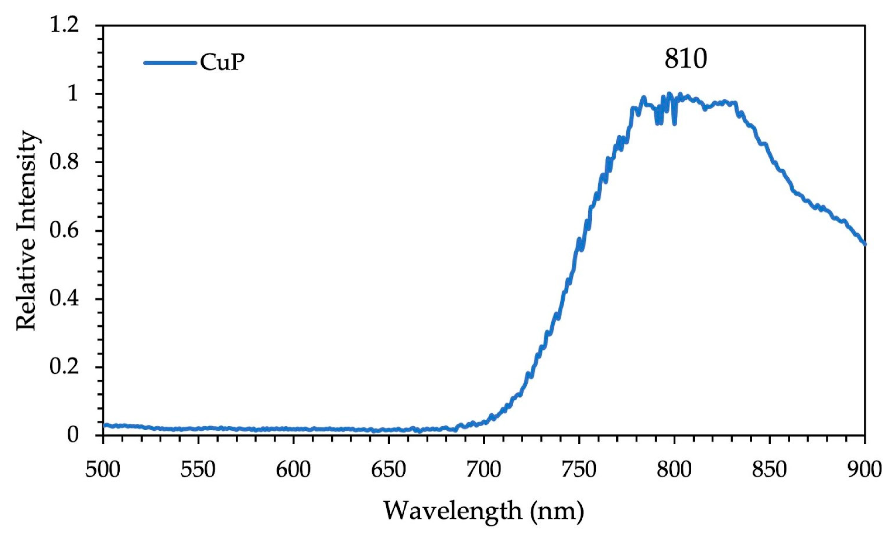
| CuP | 418 (5.5); 541 (4.2); 579 (4.0) | 421; 545 | ____ | 810 | ____ |
| ZnP | 423 (5.6); 550 (4.3); 590 (4.1) | 451; 560 | 601; 652 | 613; 654; 718 | 0.13 |
| Compound | EHOMO (eV) | ELUMO (eV) | GAP (eV) |
|---|---|---|---|
| H2P | −5.20 | −3.20 | 2.00 |
| ZnP | −5.10 | −3.00 | 2.10 |
| CuP | −5.20 | −3.00 | 2.20 |
© 2019 by the authors. Licensee MDPI, Basel, Switzerland. This article is an open access article distributed under the terms and conditions of the Creative Commons Attribution (CC BY) license (http://creativecommons.org/licenses/by/4.0/).
Share and Cite
de Amorim Lima, N.M.; Camargo Avila, H.J.; do Nascimento Marchiori, C.F.; Gondim Sampaio, S.; Ferreira Mota, J.P.; Gomes Pereira Ribeiro, V.; da Silva Clemente, C.; Mele, G.; Cremona, M.; Mazzetto, S.E. Light-Emitting Porphyrin Derivative Obtained from a Subproduct of the Cashew Nut Shell Liquid: A Promising Material for OLED Applications. Materials 2019, 12, 1063. https://doi.org/10.3390/ma12071063
de Amorim Lima NM, Camargo Avila HJ, do Nascimento Marchiori CF, Gondim Sampaio S, Ferreira Mota JP, Gomes Pereira Ribeiro V, da Silva Clemente C, Mele G, Cremona M, Mazzetto SE. Light-Emitting Porphyrin Derivative Obtained from a Subproduct of the Cashew Nut Shell Liquid: A Promising Material for OLED Applications. Materials. 2019; 12(7):1063. https://doi.org/10.3390/ma12071063
Chicago/Turabian Stylede Amorim Lima, Nayane Maria, Harold José Camargo Avila, Cleber Fabiano do Nascimento Marchiori, Samuel Gondim Sampaio, João Paulo Ferreira Mota, Viviane Gomes Pereira Ribeiro, Claudenilson da Silva Clemente, Giuseppe Mele, Marco Cremona, and Selma Elaine Mazzetto. 2019. "Light-Emitting Porphyrin Derivative Obtained from a Subproduct of the Cashew Nut Shell Liquid: A Promising Material for OLED Applications" Materials 12, no. 7: 1063. https://doi.org/10.3390/ma12071063