
Opoka—Sediment Rock as New Type of Hybrid Mineral Filler for Polymer Composites

 ,
,  , and
, and
Abstract
:1. Introduction
2. Materials and Methods
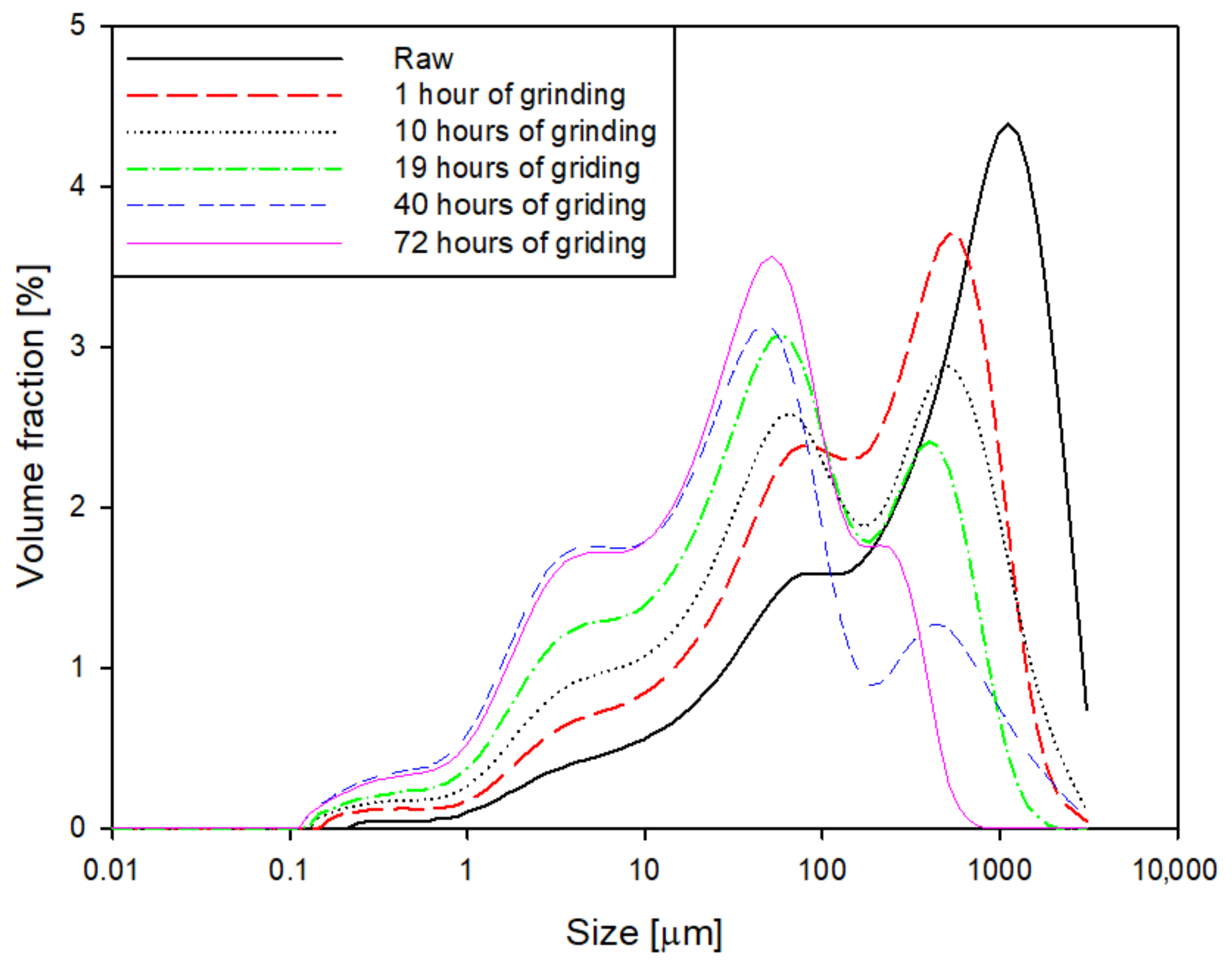
2.1. Particle Size Distribution
2.2. pH Measurements
- -
- 25 mL of distilled water for the first series
- -
- 25 mL of 1 M KCl for the second series.
2.3. X-ray Diffraction Analysis
2.4. Digital Light Microscopy
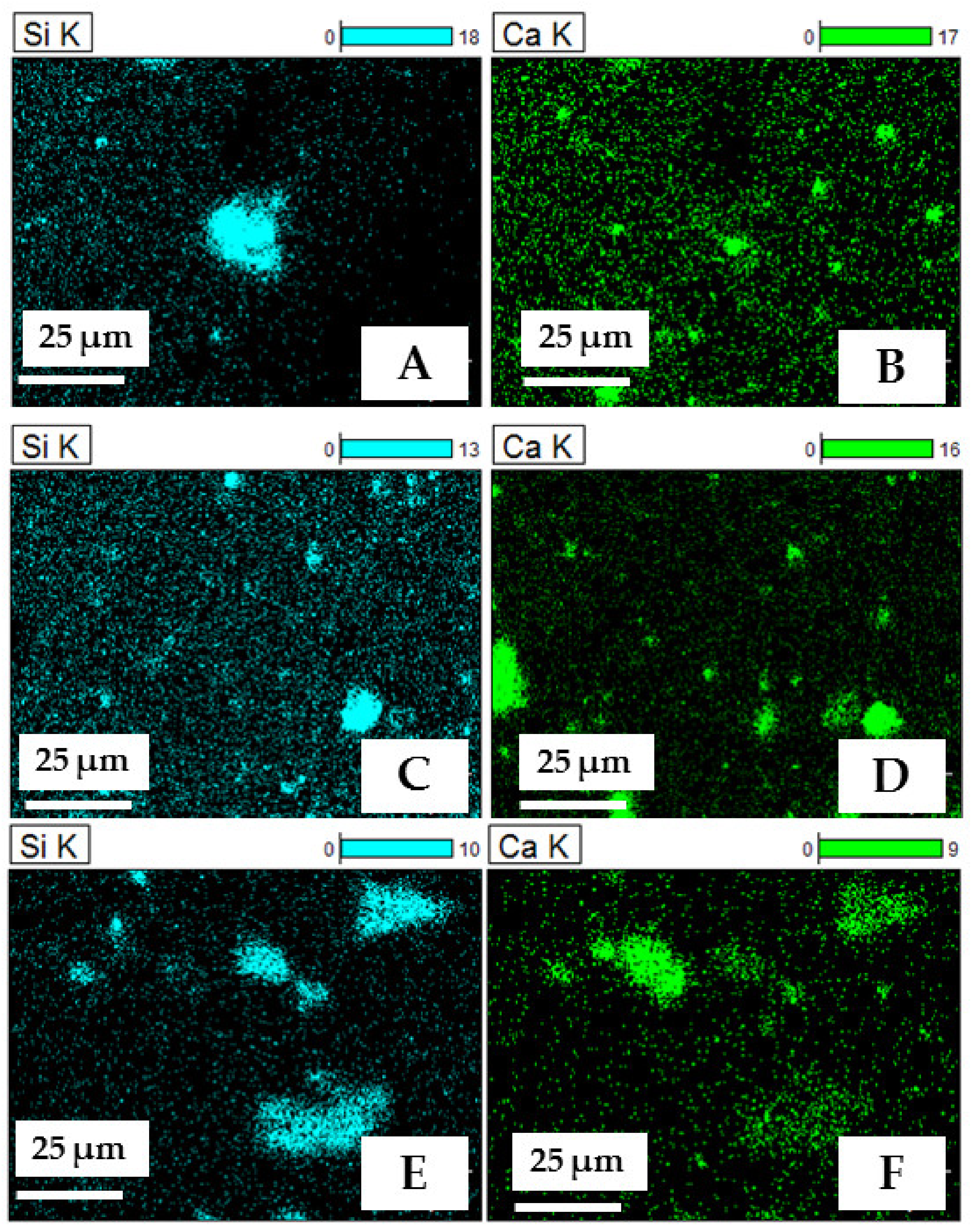
2.5. SEM and SEM—EDS (Energy Dispersive Spectroscopy) Analysis
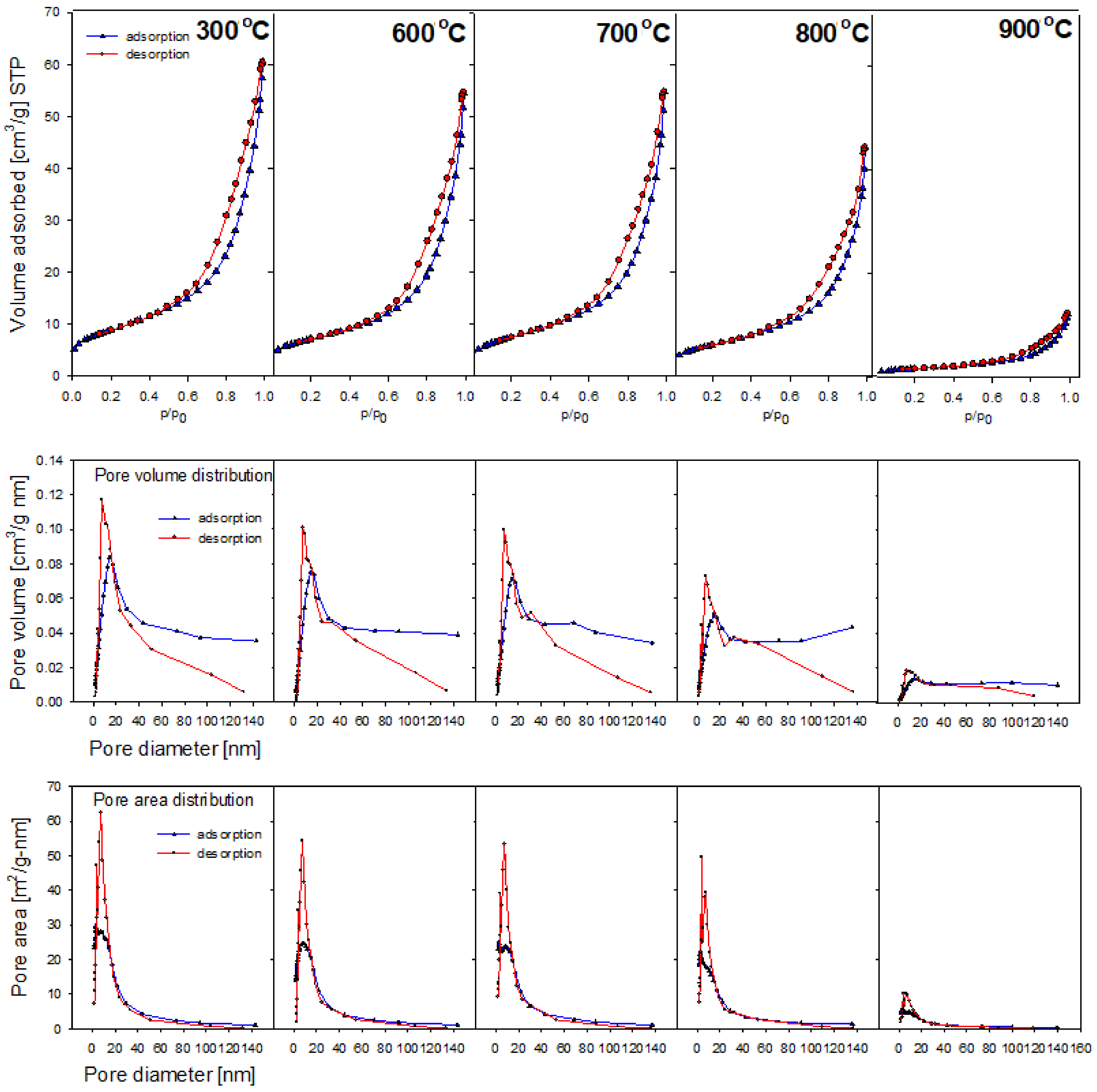
2.6. Porous Structure
2.7. FTIR Measurements
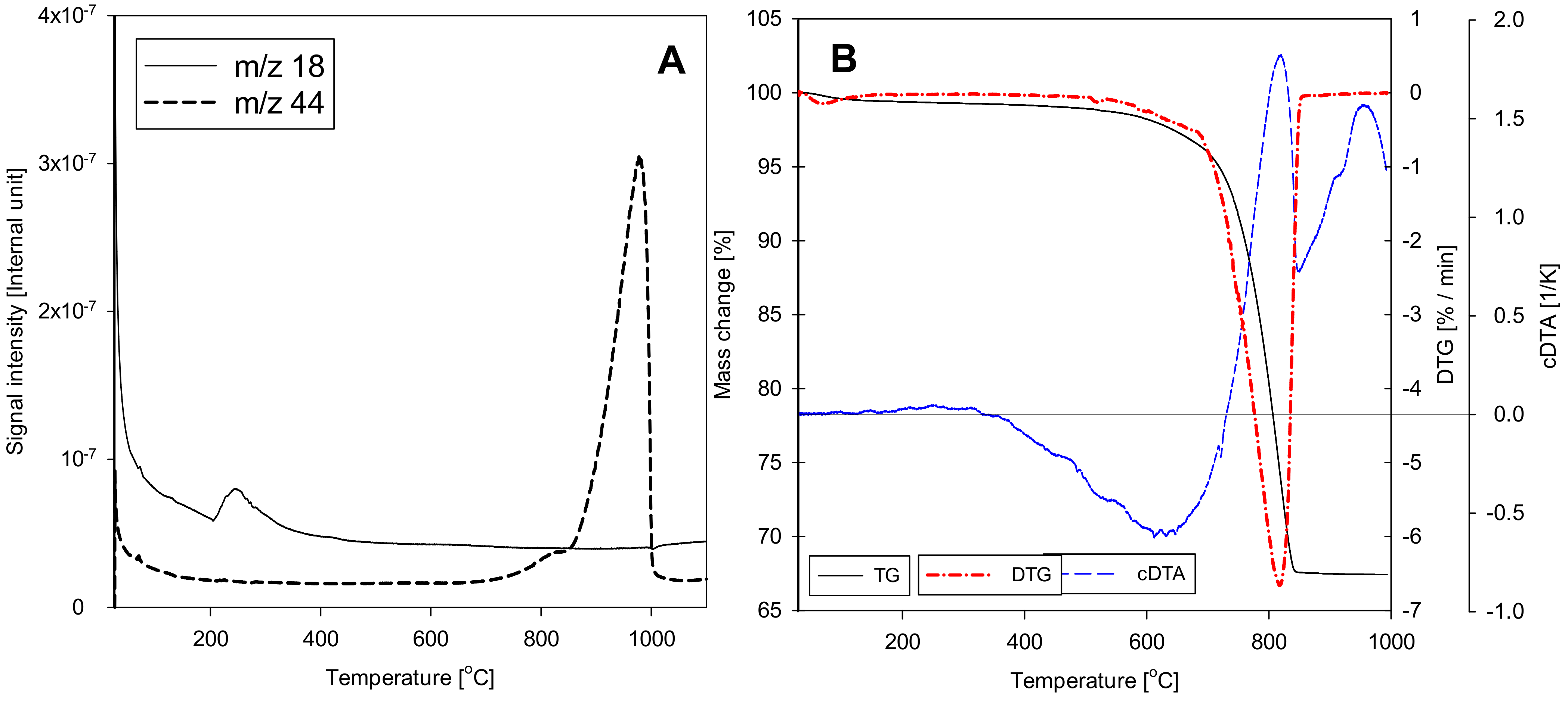
2.8. Thermogravimetry
2.9. Mechanical Properties
2.10. Preparation of Composites
3. Results and Discussion
4. Conclusions
- (1)
- It has been shown that opoka can be an effective hybrid filler in thermoplastic systems. The mechanical properties of the composite are comparable to those of the reference materials used (Aerosil 200 silica and CaCO3), proving opoka applicability.
- (2)
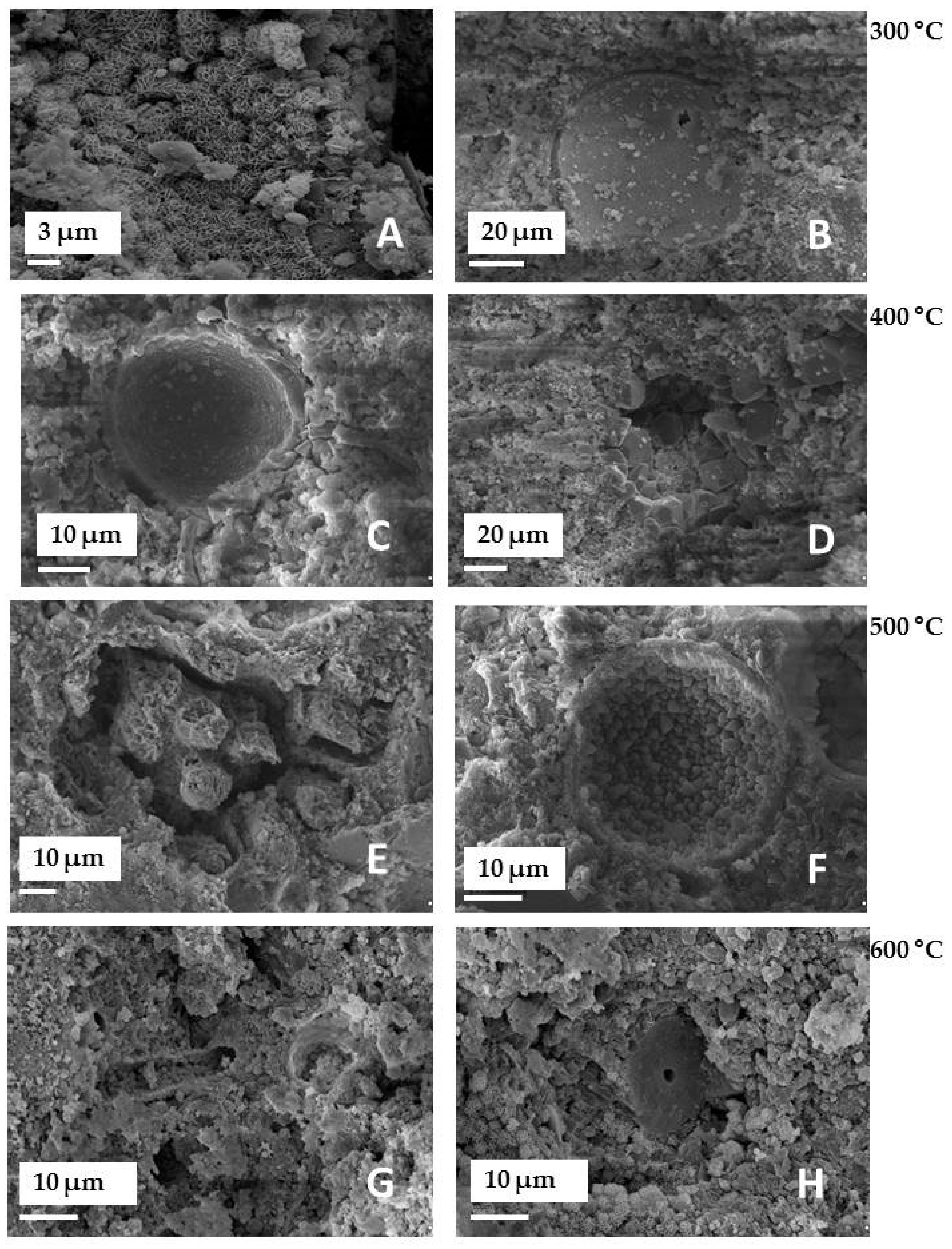
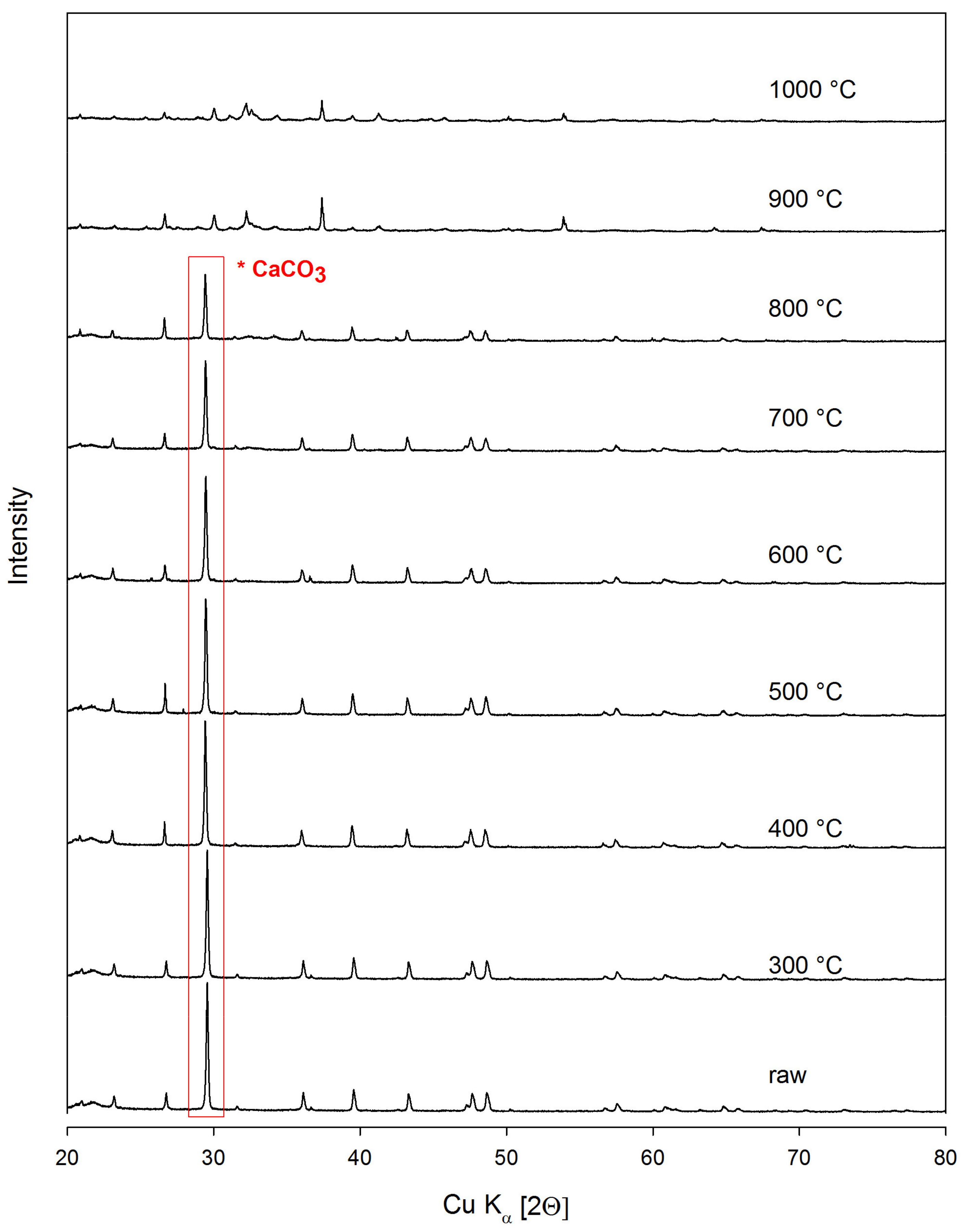
- Heat treatment has a significant influence on the structural properties, morphology, as well as the alkalinity of the mineral. For this reason, it is possible to direct the desired material properties depending on the needs. E.g. the alkalinity of the material can be increased easily or the porosity can be reduced. As a result of structural and chemical transformations after the thermal treatment, an improvement in the dispersion degree of the filler in the matrix was observed, as well as subtle differences in the mechanical properties of the composites formed (increased elongation at break).
- (3)
- Despite the fact that the opoka rock’s particle size is several times larger than that of the chalk or silica used in the study, it shows satisfactory behaviour in thermoplastic composites. Opoka composites possess similar susceptibility to deformation without breaking comparing to those filled with chalk or synthetic silica. However, secondary agglomeration of the filler indicates that it is not fully compatible with the polymer matrix due to the unfavourable physicochemical properties of the particles’ surface. This indicates the necessity of chemical surface treatment, e.g., with the use of silane coupling agents. The above observations point out that, after appropriate micronisation, opoka rock may be a superior mineral filler when compared with chalk.
- (4)
- It has been shown that the thermogravimetric method is accurate in determination of the CaCO3 content in limestone rocks. There is a great agreement of results between this technique and EDS. However, the accuracy of the TG method is higher than that of the EDS, which working principle is based on measuring the very thin layer near the surface of the sample, and not the full volume of the sample.
- (5)
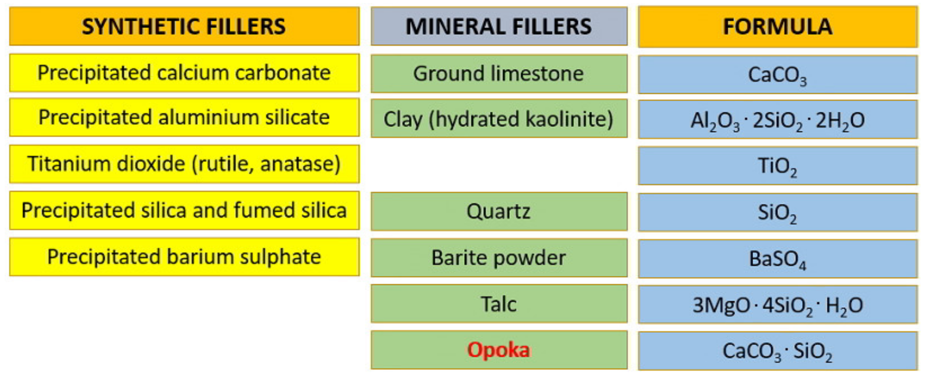
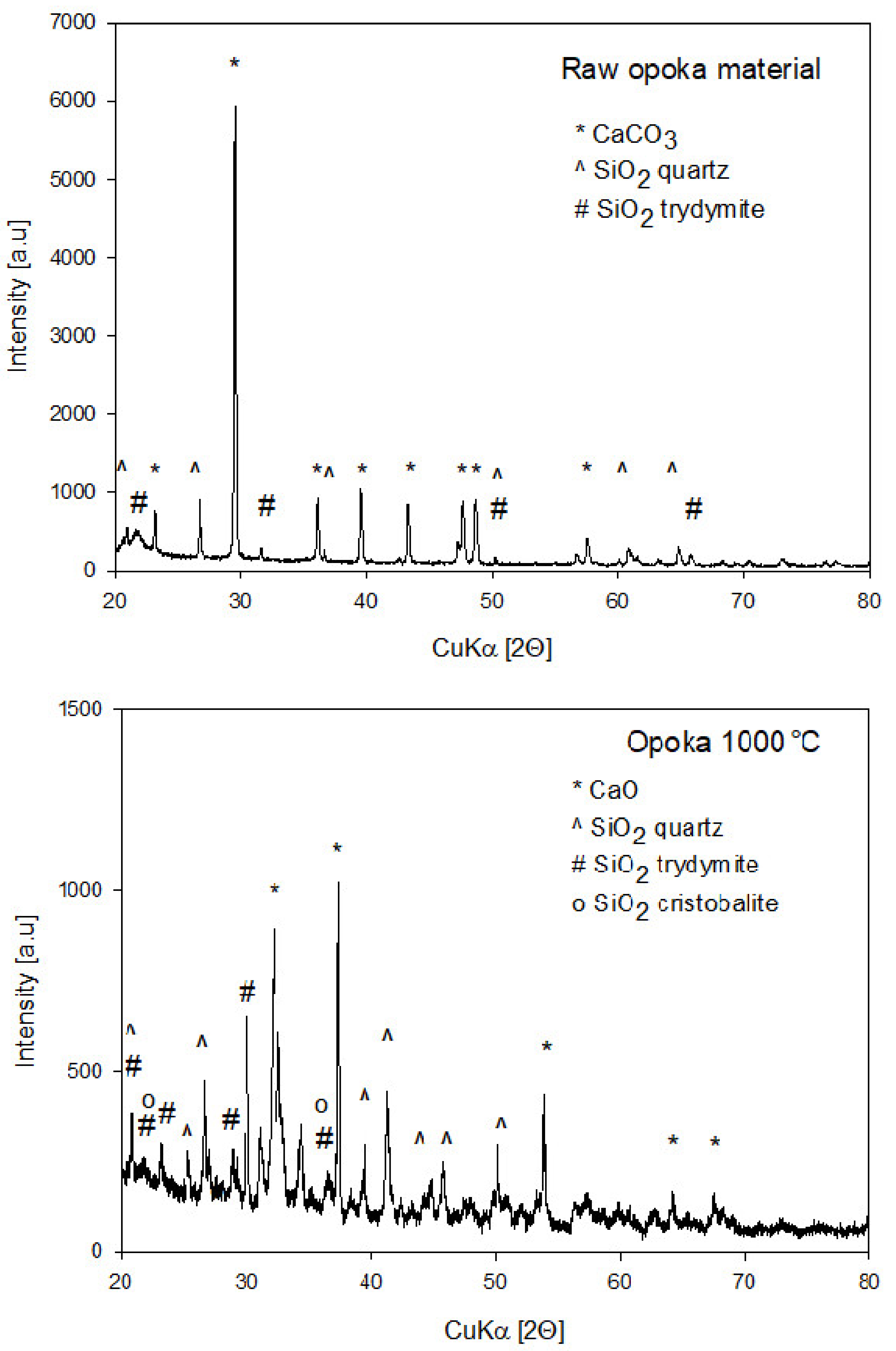
- The observed complexity and structural heterogeneity may be a significant advantage of this raw material over synthetic options. It proves that mineral materials of more complex composition than single ingredient ones (such as synthetic chalk or SiO2), often occurring as natural raw materials, may be effectively conditioned into proper polymer fillers upon simple physical treatment, such as micronisation and calcination.
Author Contributions
Funding
Institutional Review Board Statement
Informed Consent Statement
Data Availability Statement
Conflicts of Interest
References
- Hubbe, M.; Gill, R.A. Fillers for Papermaking: A Review of their Properties, Usage Practices, and their Mechanistic Role. BioResources 2016, 11, 2886–2963. [Google Scholar] [CrossRef] [Green Version]
- Unterweger, C.; Duchoslav, J.; Stifter, D.; Fürst, C. Characterization of carbon fiber surfaces and their impact on the mechanical properties of short carbon fiber reinforced polypropylene composites. Compos. Sci. Technol. 2015, 108, 41–47. [Google Scholar] [CrossRef]
- John, J.; Gangadhar, S.A.; Shah, I. Flexural strength of heat-polymerized polymethyl methacrylate denture resin reinforced with glass, aramid, or nylon fibers. J. Prosthet. Dent. 2001, 86, 424–427. [Google Scholar] [CrossRef] [PubMed]
- Mohanty, A.K.; Misra, M.; Drzal, L.T. Natural Fibers. In Biopolymers and Biocomposites, 1st ed.; CRC Press: Boca Raton, FL, USA, 2005. [Google Scholar]
- Buasri, A.; Chaiyut, N.; Borvornchettanuwat, K.; Chantanachai, N.; Thonglor, K. Thermal and Mechanical Properties of Modified CaCO3/PP Nanocomposites. Int. J. Civ. Environ. Eng. 2012, 6, 374–377. [Google Scholar]
- Kahraman, M.; Kızılca, N.; Oral, M.A. Influence of mica mineral on flame retardancy and mechanical properties of intumescent flame retardant polypropylene composites. Open Chem. 2021, 19, 904–915. [Google Scholar] [CrossRef]
- Kenig, S. Processing of Polymer Nanocomposites; Carl Hanser Verlag GmbH & Company KG: Munich, Germany, 2019; p. 520. [Google Scholar]
- Dekkers, M.E.; Heikens, D. The Effect of Interfacial Adhesion on the tensile Behavior of Polystyrene-Glass-Bead Composites. J. Appl. Polym. Sci. 1988, 28, 3809–3815. [Google Scholar] [CrossRef] [Green Version]
- Fuad, M.Y.A.; Hanim, H.; Zarina, R.; Ishak, Z.A.M.; Hassan, A. Polypropylene/calcium carbonate nanocomposites–effects of processing techniques and maleated polypropylene compatibiliser. Express Polym. Lett. 2010, 4, 611–620. [Google Scholar] [CrossRef]
- Palutkiewicz, P.; Trzaskalska, M.; Bociąga, E. The influence of blowing agent addition, talc filler content, and injection velocity on selected properties, surface state, and structure of polypropylene injection molded parts. Cell. Polym. 2020, 39, 3–30. [Google Scholar] [CrossRef]
- Liang, J.Z. Evaluation of dispersion of nano-CaCO3 particles in polypropylene matrix based on fractal method. Compos. Part A Appl. Sci. Manuf. 2007, 38, 1502–1506. [Google Scholar] [CrossRef]
- Sprynskyy, M. Heterogeniczność Strukturalna Oraz Właściwości Adsorpcyjne Adsorbentów Naturalnych (Klinoptylolit, Mordenit, Diatomit, Talk, Chryzotyl; Wydawnictwo Naukowe Uniwersytetu Mikołaja Kopernika: Toruń, Poland, 2012. [Google Scholar]
- Nasution, H.; Harahap, H.; Pandi, S.; Wijaya, F. Comparison of Silica and Zeolite as Fillers on Unsaturated Polyester Resin (UPR) Composites: The Effect on Tensile Properties. In Proceedings of the International Conference of Science, Technology, Engineering, Environmental and Ramification Researches (ICOSTEERR 2018)—Research in Industry 4.0, Medan, Indonesia, 30–31 August 2018; pp. 227–231. [Google Scholar]
- Mittal, P.; Naresh, S.; Luthra, P.; Singh, A.; Dhaliwal, J.S.; Kapur, G.S. Polypropylene composites reinforced with hybrid inorganic fillers: Morphological, mechanical, and rheological properties. J. Thermoplast. Compos. Mater. 2019, 32, 848–864. [Google Scholar] [CrossRef]
- Jakubowska, P.; Osińska-Broniarz, M.; Martyla, A.; Sztorch, B.; Sierczyńska, A.; Kopczyk, M.; Przekop, R. Thermal properties of PP-SiO2 composites filled with Stöber silica. Compos. Theory Pract. 2016, 6, 161–166. [Google Scholar]
- Cazan, C.; Enesca, A.; Andronic, L. Synergic Effect of TiO2 Filler on the Mechanical Properties of Polymer Nanocomposites. Polymers 2021, 13, 2017. [Google Scholar] [CrossRef]
- Dobrosielska, M.; Przekop, R.E.; Sztorch, B.; Brząkalski, D.; Zgłobnicka, I.; Łępicka, M.; Dobosz, R.; Kurzydłowski, K.J. Biogenic Composite Filaments Based on Polylactide and Diatomaceous Earth for 3D Printing. Materials 2020, 13, 4632. [Google Scholar] [CrossRef]
- Ammar, O.; Bouaziz, Y.; Haddar, N.; Mnif, N. Talc as Reinforcing Filler in Polypropylene Compounds: Effect on Morphology and Mechanical Properties. Polym. Sci. 2017, 3, 1–7. [Google Scholar]
- Xanthos, M. Functional Fillers for Plastics, 2nd ed.; Wiley-VCH: Weinheim, Germany, 2010. [Google Scholar]
- Rothon, R.N. Particulate Fillers for Polymers, Rapra Review Reports; Smithers Rapra Technology: Shawbury, UK, 2001. [Google Scholar]
- Bus, A.; Karczmarczyk, A. Infrastruktura I Ekologia Terenów Wiejskich; Polska Akademia Nauk: Kraków, Poland, 2014; p. 227. [Google Scholar]
- Brogowski, Z.; Renman, G. Characterization of Opoka as a Basis for its Use in Wastewater Treatment. Pol. J. Environ. Stud. 2004, 13, 15–20. [Google Scholar]
- Pinińska, J. Właściwości geomechaniczne opok. Górnictwo I Geoinżynieria 2008, 32, 293–301. [Google Scholar]
- Marzec, M.; Pieńko, A.; Gizińska-Górna, M.; Pytka, A.; Jóźwiakowski, K.; Sosnowska, B.; Kamińska, A.; Listosz, A. The use of carbonate-silica rock (opoka) to remove iron, manganese and indicator bacteria from groundwater. J. Water Land Dev. 2017, 34, 19–204. [Google Scholar] [CrossRef]
- Wyrwicka, K. Wykształcenie litologiczne i węglanowe surowce skalne mastrychtu lubelskiego. Biul. PIG 1977, 299, 5–98. [Google Scholar]
- Żaba, J. Ilustrowany Słownik Skał I Minerałów; Wyd. VIDEOGRAF: Katowice, Poland, 2003. [Google Scholar]
- Thomas, G.W. Soil pH and soil acidity. In Methods of Soil Analysis: Part 3-Chemical Methods; Bigham, J.M., Ed.; Soil Science Society of America Book Series No. 5; Soil Science Society of America and American Society of Agronomy: Madison, WI, USA, 1996; pp. 475–490. [Google Scholar]
- Karunadasa, K.S.P.; Manoratne, C.H.; Pitawala, H.M.T.G.A.; Rajapakse, R.M.G. Thermal decomposition of calcium carbonate (calcite polymorph) as examined by in-situ high-temperature X-ray powder diffraction. J. Phys. Chem. Solids 2019, 134, 21–28. [Google Scholar] [CrossRef]
- Curry, M.D.; Boston, P.J.; Spilde, M.N.; Baichtal, J.F.; Campbell, A.R. Cottonballs, a unique subaqeous moonmilk, and abundant subaerial moonmilk in Cataract Cave, Tongass National Forest, Alaska. Int. J. Speleol. 2009, 38, 111–128. [Google Scholar] [CrossRef] [Green Version]
- Wyszomirski, P.; Szydłak, T.; Pichniarczyk, P. Charakterystyka surowcowa wybranych kruszyw mineralnych NE Polski w aspekcie trwałości betonów. Zesz. Nauk. Inst. Gospod. Surowcami Miner. I Energią Pol. Akad. Nauk. 2016, 96, 363–378. [Google Scholar]
- Smalakys, G.; Siauciunas, R. The synthesis of 1.13 nm tobermorite from carbonated opoka. J. Therm. Anal. Calorim. 2018, 134, 493–502. [Google Scholar] [CrossRef]
- RRUFF Sample Data. Available online: http://rruff.info/crishttptobalite/R060648:%2005.07.2021 (accessed on 26 June 2021).
- RRUFF Sample Data. Available online: http://rruff.info/Tridymite/R090042:%2005.07.2021 (accessed on 26 June 2021).
- Vichaphund, S.; Kitiwan, M.; Atong, D.; Thavorniti, P. Microwave synthesis of wollastonite powder from eggshells. J. Eur. Ceram. Soc. 2011, 13, 2435–2440. [Google Scholar] [CrossRef]
- Zhu, L.; Sohn, H.Y. Growth of 2M-Wollastonite Polycrystals by a Partial Melting and Recrystallization Process for the Preparation of High-Aspect-Ratio Particles. J. Ceram. Sci. Technol. 2012, 3, 169–180. [Google Scholar]
- Rodriguez-Blanco, J.D.; Shaw, S.; Benning, L.G. The kinetics and mechanisms of amorphous calcium carbonate (ACC) crystallization to calcite, via vaterite. Nanoscale 2011, 3, 265–271. [Google Scholar] [CrossRef]
- Mroczkowska-Szerszeń, M.; Orzechowski, M. Infrared spectroscopy methods in reservoir rocks analysis–semiquantitative approach for carbonate rocks. Naft.-Gaz 2018, 11, 802–812. [Google Scholar] [CrossRef]
- Correcher, V.; Garcia-Guinea, J.; Bustillo, M.A.; Garcia, R. Study of the thermoluminescence emission of a natural α-crystobalite. Radiat. Eff. Defects Solids 2009, 164, 59–67. [Google Scholar] [CrossRef]
- Wilson, J. The structure of opal-CT revisited. J. Non-Cryst. Solids 2014, 405, 68–75. [Google Scholar] [CrossRef]
- Cheng, Y.; Liu, J.; Zhang, H.; Dai, L.; Wei, B.; Chang, Q. Increasing the hydrophobicity of filter medium particles for oily water treatment using coupling agents. Heliyon 2018, 4, e00809. [Google Scholar]
- Kezuka, Y.; Kawai, K.; Eguchi, K.; Tajika, M. Fabrication of Single-Crystalline Calcite Needle-Like Particles Using the Aragonite–Calcite Phase Transition. Minerals 2017, 7, 133. [Google Scholar] [CrossRef] [Green Version]
- Kloziński, A.; Jakubowska, P.; Przybylska, J.E.; Przekop, R. Application of Application of in-line rheological measurements for characterization of polypropylene/opoka rock powder composites. Polimery 2019, 64, 282–289. [Google Scholar] [CrossRef] [Green Version]
- Teixeira, S.C.S.; Moreira, M.M.; Lima, A.P.; Santos, L.S.; Rocha, B.M.; Lima, E.S.; Costa, R.A.A.F.; Silva, A.L.N.; Rocha, M.C.G.; Coutinho, F.M.B. Composites of high density polyethylene and different grades of calcium carbonate: Mechanical, rheological, thermal, and morphological properties. J. Appl. Polym. Sci. 2006, 101, 2559–2564. [Google Scholar] [CrossRef]
- Lazzeri, A.; Zebarjad, S.M.; Pracella, M.; Cavalier, K.; Rosa, R. Filler toughening of plastics. Part 1—The effect of surface interactions on physico-mechanical properties and rheological behaviour of ultrafine CaCO3/HDPE nanocomposites. Polymer 2005, 46, 827–844. [Google Scholar] [CrossRef]
- Silva, A.L.N.; Rocha, M.C.G.; Moraes, M.A.R.; Valente, C.A.R.; Coutinho, F.M.B. Mechanical and rheological properties of composites based on polyolefin and mineral additives. Polym. Test. 2002, 21, 57–60. [Google Scholar] [CrossRef]
- Zuiderduin, W.J.C.; Westzaan, C.; Huetink, J.; Gaymans, R.J. Toughening of polypropylene with calcium carbonate particles. Polymer 2003, 44, 261–275. [Google Scholar] [CrossRef]
- Chang, H.J.; Morikawa, J.; Hashimoto, T. Thermal diffusivity of polyolefins by temperature wave analysis. J. Appl. Polym. Sci. 2006, 99, 1104–1110. [Google Scholar] [CrossRef]
- Thio, Y.S.; Argon, A.S.; Cohen, R.E.; Weinberg, M. Toughening of isotactic polypropylene with CaCO3 particles. Polymer 2002, 43, 3661–3674. [Google Scholar] [CrossRef]
- Dorigato, A.; D’Amato, M.; Pegoretti, A. Thermo-mechanical properties of high density polyethylene–fumed silica nanocomposites: Effect of filler surface area and treatment. J. Polym. Res. 2012, 19, 9889. [Google Scholar] [CrossRef]
- Tomaszewska, J.; Klapiszewski, Ł.; Skórczewska, K.; Szalaty, T.J.; Jesionowski, T. Advanced organic-inorganic hybrid fillers as functional additives for poly(vinyl chloride. Polimery 2017, 62, 19–26. [Google Scholar] [CrossRef]
- Li, K.; Ren, D.; Tang, X.; Xu, M.; Liu, X. Micro/Mesoporous Fe3O4/Fe-Phthalocyanine Microspheres and Effects of Their Surface Morphology on the Crystallization and Properties of Poly(Arylene Ether Nitrile) Composites. Materials 2018, 11, 1356. [Google Scholar] [CrossRef] [Green Version]


| Phase | CaK/SiK/OK | SiK/CaK/OK | ||
|---|---|---|---|---|
| Atomic Content (%) | ||||
| Raw | O | 73.23 | 73.12 | |
| Mg | - | - | ||
| Al | 0.60 | 0.88 | ||
| Si | 8.25 | 13.93 | ||
| Ca | 17.92 | 12.06 | ||
| Total phase | 45.00 | 55.00 | ||
| Phase | CaSiO-1 | CaSiO-2 | CaSiO-3 | |
| Atomic Content (%) | ||||
| 1000 °C | O | 60.65 | 64.93 | 63.63 |
| Mg | 0.23 | 0.19 | 0.32 | |
| Al | 0.69 | 0.87 | 0.34 | |
| Si | 12.77 | 16.80 | 5.76 | |
| Ca | 25.66 | 17.21 | 29.94 | |
| Total phase | 54.00 | 22.00 | 24.00 | |
| Sample | pH in H2O | pH in 1 M KCl |
|---|---|---|
| Raw | 8.35 | 8.41 |
| 300 °C | 10.39 | 10.03 |
| 400 °C | 10.19 | 9.95 |
| 500 °C | 10.28 | 10.12 |
| 600 °C | 10.71 | 11.00 |
| 700 °C | 11.18 | 11.47 |
| 800 °C | 12.29 | 12.67 |
| 900 °C | 12.62 | 12.81 |
| 1000 °C | 12.65 | 12.76 |
| Sample Name | BET Surface Area (m2/g) | Pore Volume A (cm3/g) | Pore Volume D (cm3/g) | Pore Size A (nm) | Pore Size D (nm) |
|---|---|---|---|---|---|
| Raw | 12.1 | 0.04 | 0.04 | 14.7 | 12.4 |
| 300 °C | 31.4 | 0.09 | 0.09 | 113.6 | 9.9 |
| 400 °C | 30.3 | 0.09 | 0.09 | 114.1 | 10.1 |
| 500 °C | 31.2 | 0.09 | 0.09 | 115.9 | 10.1 |
| 600 °C | 24.9 | 0.08 | 0.08 | 127.6 | 11.1 |
| 700 °C | 26.9 | 0.08 | 0.08 | 119.5 | 10.4 |
| 800 °C | 21.7 | 0.07 | 0.07 | 118.3 | 10.1 |
| 900 °C | 5.7 | 0.02 | 0.02 | 127.2 | 10.9 |
| 1000 °C | 3.4 | 0.01 | 0.01 | 151.1 | 11.9 |
| Sample | Et, GPa | σM, MPa | εB, % | Ef, GPa | Ffc, N | HS, 0Sh |
|---|---|---|---|---|---|---|
| PP | 1.29 ± 0.01 | 32.3 ± 0.41 | 45.2 ± 3.58 | 1.30 ± 0.01 | 54.9 ± 0.76 | 61.8 ± 0.1 |
| C5 | 1.46 ± 0.01 | 33.5 ± 0.05 | 28.6 ± 2.60 | 1.39 ± 0.02 | 59.3 ± 0.87 | 62.2 ± 0.1 |
| A5 | 1.35 ± 0.03 | 34.2 ± 0.14 | 30.0 ± 3.75 | 1.37 ± 0.01 | 63.1 ± 0.61 | 61.9 ± 0.2 |
| O5 | 1.49 ± 0.01 | 32.6 ± 0.31 | 24.2 ± 5.73 | 1.38 ± 0.02 | 61.5 ± 0.54 | 63.8 ± 0.1 |
| O5_800 | 1.42 ± 0.02 | 32.3 ± 0.35 | 29.4 ± 3.25 | 1.38 ± 0.02 | 59.9 ± 0.48 | 62.6 ± 0.1 |
| O5_1000 | 1.38 ± 0.02 | 32.0 ± 0.35 | 30.2 ± 5.52 | 1.33 ± 0.02 | 58.8 ± 0.25 | 62.1 ± 0.2 |
Publisher’s Note: MDPI stays neutral with regard to jurisdictional claims in published maps and institutional affiliations. |
© 2021 by the authors. Licensee MDPI, Basel, Switzerland. This article is an open access article distributed under the terms and conditions of the Creative Commons Attribution (CC BY) license (https://creativecommons.org/licenses/by/4.0/).
Share and Cite
Przekop, R.E.; Jakubowska, P.; Sztorch, B.; Kozera, R.; Dydek, K.; Jałbrzykowski, M.; Osiecki, T.; Marciniak, P.; Martyła, A.; Kloziński, A.; et al. Opoka—Sediment Rock as New Type of Hybrid Mineral Filler for Polymer Composites. AppliedChem 2021, 1, 90-110. https://doi.org/10.3390/appliedchem1020008
Przekop RE, Jakubowska P, Sztorch B, Kozera R, Dydek K, Jałbrzykowski M, Osiecki T, Marciniak P, Martyła A, Kloziński A, et al. Opoka—Sediment Rock as New Type of Hybrid Mineral Filler for Polymer Composites. AppliedChem. 2021; 1(2):90-110. https://doi.org/10.3390/appliedchem1020008
Chicago/Turabian StylePrzekop, Robert E., Paulina Jakubowska, Bogna Sztorch, Rafał Kozera, Kamil Dydek, Marek Jałbrzykowski, Tomasz Osiecki, Piotr Marciniak, Agnieszka Martyła, Arkadiusz Kloziński, and et al. 2021. "Opoka—Sediment Rock as New Type of Hybrid Mineral Filler for Polymer Composites" AppliedChem 1, no. 2: 90-110. https://doi.org/10.3390/appliedchem1020008