Article

g-C3N4/MoS2 Heterojunction for Photocatalytic Removal of Phenol and Cr(VI)

by
Ilaeira Rapti
1,
Feidias Bairamis
1 and
Ioannis Konstantinou
1,2,*
1
Department of Chemistry, University of Ioannina, 45100 Ioannina, Greece
2
Institute of Environment and Sustainable Development, University Research Center of Ioannina (URCI), 45110 Ioannina, Greece
*
Author to whom correspondence should be addressed.
Photochem 2021, 1(3), 358-370; https://doi.org/10.3390/photochem1030023
Submission received: 22 September 2021 / Revised: 10 October 2021 / Accepted: 12 October 2021 / Published: 15 October 2021

Abstract

:
In this study, molybdenum disulfide (MoS2) decorated on graphitic carbon nitride (g-C3N4) heterostructure catalysts at various weight ratios (0.5%, 1%, 3%, 10%, w/w) were successfully prepared via a two-step hydrothermal synthesis preparation method. The properties of the synthesized materials were studied by X-ray diffraction (XRD), attenuated total reflectance–Fourier transform infrared spectroscopy (ATR-FT-IR), UV–Vis diffuse reflection spectroscopy (DRS), scanning electron microscopy (SEM) and N2 porosimetry. MoS2 was successfully loaded on the g-C3N4 forming heterojunction composite materials. N2 porosimetry results showed mesoporous materials, with surface areas up to 93.7 m2g−1, while determined band gaps ranging between 1.31 and 2.66 eV showed absorption over a wide band of solar light. The photocatalytic performance was evaluated towards phenol oxidation and of Cr(VI) reduction in single and binary systems under simulated sunlight irradiation. The optimum mass loading ratio of MoS2 in g-C3N4 was 1%, showing higher photocatalytic activity under simulated solar light in comparison with bare g-C3N4 and MoS2 for both oxidation and reduction processes. Based on scavenging experiments a type-II photocatalytic mechanism is proposed. Finally, the catalysts presented satisfactory stability (7.8% loss) within three catalytic cycles. Such composite materials can receive further applications as well as energy conversion.

Graphical Abstract

1. Introduction

Energy crisis and environmental pollution are currently among the most serious problems for humans [1]. Emerging and priority environmental pollutants comprise several chemical categories such as pharmaceuticals, pesticides and plasticizers. Phenol and in general phenolics may be present in several wastewater streams from different production processes as well as degradation products from the previously mentioned pollutants. In addition, toxic metal ions such as Cr(VI) may be present in combined wastewater streams; thus, treatment methods should be capable of removing both organic and inorganic pollutants. However, conventional treatment methods present either low removal of certain organic pollutants or are incapable of simultaneous removal of organics and toxic metal ions [2]. Therefore, there has been an increased interest in the development of more efficient and environmentally friendly methods for the removal of pollutants from wastewater, and for this reason the advanced oxidation processes (AOPs) are widely used. Their effectiveness for organics removal is based on the production of hydroxyl radicals, which are powerful oxidizing agents. Heterogeneous photocatalysis, which presents advantages over other removal techniques as it can be applied for both oxidation and reduction of pollutants in ambient conditions in the presence of solar radiation and for organic pollutants, can lead to complete mineralization [2,3,4,5,6].
Graphitic carbon nitride (g-C3N4) has drawn widespread attention and become a hotspot in various scientific disciplines as a metal-free semiconductor due to its advantages. It has an appealing electronic structure with a 2.7 eV band gap, it can be fabricated with low-cost precursors (e.g., urea, thiourea, melamine) [3,7,8] and it is environmentally friendly. However, the rapidly photogenerated electron–hole recombination diminishes the photocatalytic efficiency. The coupling of g-C3N4 with other semiconductors with an appropriate band gap was considered to increase photocatalytic efficiency.
Molybdenum sulfide (MoS2) has attracted attention as an emerging photocatalytic cocatalyst material due to its distinctive features, such as high stability and hardness, reliability, non-toxicity and low cost. It possesses a narrow band gap (1.2–1.9 eV), which offers a wide spectral absorption range and provides high speed channels for the interfacial charge transfer in heterostructures [3]. Previous studies have explored the application of MoS2 in Cr(VI) reduction. Photoreduction and chemical reduction (redox between MoS2 and Cr(VI)) were determined through a collaborative contribution to reducing Cr(VI) by MoS2 under light conditions [9,10,11]. The coupling of two semiconductors (MoS2, g-C3N4) could significantly reduce the charge carrier recombination and highly improve photocatalytic activity compared to those bare materials. MoS2/g-C3N4 has been synthesized and tested for energy conversion, as a supercapacitor and for organic dye degradation [3,12,13,14,15]; however, its application to the simultaneous oxidation/reduction of environmental pollutants has not been studied so far.
Based on the above, the present study deals with the preparation of a series of MoS2/g-C3N4 heterostructure composite catalysts and their application for the removal of phenol and Cr(VI) for aqueous solutions. There are few works exploring the synthesis of MoS2/g-C3N4 heterojunction structure via various methods such as hydrothermal treatment, impregnation-sulfidation and photodeposition [16,17,18,19]. Here, a two-step hydrothermal synthesis combined with a sonication–liquid exfoliation preparation method is proposed.

2. Materials and Methods

2.1. Materials and Chemicals

Urea (99.5%, Mw: 60.06 gmol−1), thiourea (>99%, Mw: 76.12 gmol−1) and 1,5-diphenyl carbazide (98% (Mw: 242.28) were obtained from Acros Organics (Geel, Belgium). Ammonium molybdate tetrahydrate (99%, Mw: 1235.86 gmol−1) was supplied by Janssen Chimica. Potassium dichromate (KCr2O7, Mw: 294.18 gmol−1) was obtained from Sigma-Aldrich (St. Louis, MO, USA). Phenol (Mw: 94.11 gmol−1) was purchased by Merck kGaA (Darmstadt, Germany). Methanol (MeOH), sulfuric acid >95% (H2SO4), methanol HPLC grade (MeOH, Mw: 32.04 gmol−1) and water HPLC grade (Mw: 18.02 gmol−1) were supplied by Fischer Scientific (Loughborough, Leics, UK). Distilled water was used throughout the experimental procedures of the study.

2.2. Preparation of g-C3N4, MoS2 and Composite MoS2/g-C3N4 Photocatalysts

2.2.1. Synthesis of Bare Carbon Nitride (g-C3N4) and Molybdenum Disulfide (MoS2)

Graphitic carbon nitride (g-C3N4) was synthesized by thermal treatment of urea as a precursor compound. In a typical synthesis of g-C3N4, 30 g of urea was put in a crucible. After being dried at 90 °C it was heated to 500 °C at a heating rate of 10 °C/min and kept at this temperature for 4 h. The resulting yellow powder was collected and ground into a powder.
Molybdenum disulfide was prepared by hydrothermal synthesis. Hexaammonium heptamolybdate tetrahydrate and thiourea were dissolved in 10 mL of deionized water by stirring for 1 h at room temperature. The resulting solution was then placed in a Teflon-lined autoclave reactor and heated in an oven at 200 °C for 12 h.

2.2.2. Synthesis of MoS2/g-C3N4 Heterostructure

MoS2/g-C3N4 heterostructures with 0.5%, 1%, 3%, 10% (wt%) ratios were synthesized. An appropriate amount of bulk g-C3N4 was added in isopropanol into a beaker, and the mixture was sonicated for 2 h at room temperature. In a separate beaker, MoS2 nanoparticles was added in a water/isopropanol (2:1) solution, and the mixture was sonicated for 2 h at room temperature. The solutions were mixed together and sonicated for another 2 h at room temperature. The product was cleaned with water and ethanol, collected by centrifuging and dried at 60 °C [18]. Then it was calcinated in air at 200 °C for 4 h.

2.3. Material Characterization

The crystal forms of the photocatalysts were analyzed from their X-ray diffraction (XRD) patterns using a Bruker Advance D8 X-ray powder diffractometer (Billerica, MA, USA) working with Cu-Ka (λ = 1.5406 Å) radiation. Diffractograms were scanned from 2θ 10° to 90°. The patterns were assigned to crystal phases with the use of the International Center for Diffraction Data (ICCD).
Attenuated total reflectance–Fourier transform infrared spectroscopy (ATR-FT-IR) was conducted to characterize the functional groups of different catalysts. A Shimadzu IR Spirit-T spectrophotometer (Kyoto, Japan) with a QATR-S single-reflection ATR measurement attachment equipped with diamond prism was used. The photocatalysts were scanned in the range 4000–400 cm−1.
The UV–Vis diffuse reflectance spectra (DRS) of the catalyst powders were recorded using a Shimadzu 2600 spectrophotometer bearing an IRS-2600 integrating sphere (Kyoto, Japan) in the wavelength of 200–800 nm at room temperature using BaSO4 (Nacalai Tesque, extra pure reagent, Kyoto, Japan) as a reference sample.
The morphology of the catalysts was examined by scanning electron microscopy (SEM) using a JEOL JSM 5600 (Tokyo, Japan) working at 20 kV.
Nitrogen adsorption–desorption isotherms were collected by porosimetry using a Quantachrome Autosorb-1 instrument (Bounton Beach, FL, USA) at 77K. The samples (≈80 mg) were degassed at 150 °C for 3 h. The Brunauer–Emmet–Teller (BET) method was used to calculate the specific area (SSA) of each material at relative pressure between 0.05 and 0.3. The adsorbed amount of nitrogen at relative pressure P/P0 = 0.95 was used in order to calculate the total pore volume (VTOT). The Barrett, Joyner and Halenda (BJH) method was used to determine the pore size distribution (PSD) of the photocatalysts.

2.4. Photocatalytic Experiments

Photocatalytic experiments were carried out using Atlas Suntest XLS+ (Atlas, Germany) solar simulator apparatus equipped with a xenon lamp (2.2 kW) and special filters in place to prevent the transmission of wavelengths below 290 nm. During the experiments the irradiation intensity was maintained at 500 W m−2.
Aqueous solutions (100 mL) and the catalyst (10 mg) were transferred into a double-walled Pyrex glass reactor, thermostated by water flowing in the double-skin of the reactor. In binary systems the pH was adjusted to ca. 2 with sulfuric acid in order to achieve high adsorption efficiency of Cr(VI) onto the catalysts and avoid Cr(OH)3 deposition on the catalyst surface, based on previous studies [11,20]. Before exposure to light, the suspension was stirred in the dark for 30 min to ensure the establishment of adsorption–desorption equilibrium onto the catalyst surface. The obtained aliquot (5 mL) was withdrawn at different time intervals and was filtered through 0.45 μm filters in order to remove the catalyst’s particles before further analysis. Quantification of phenol for the kinetic studies in aquatic solutions was carried out by high performance liquid chromatography (HPLC) (Schimadzu, LC 10AD, Diode Array Detector SPD-M10A, Degasser DGU-14A). The column oven (Schimadzu, CTO-10A) was set at 40 °C. The mobile phase used was a mixture of water HPLC grade (50%) and methanol HPLC grade (50%). The concentration of Cr(VI) was determined by the diphenylcarbazide colorimetric method measuring the absorbance at the wavelength of 540 nm using a UV–Vis spectrophotometer (Jasco-V630, Tokyo, Japan).

3. Results and Discussion

3.1. Characterization of the Prepared Photocatalysts

3.1.1. Structural Characterization

The XRD patterns for g-C3N4, MoS2 and MoS2/g-C3N4 composites are shown in Figure 1. For g-C3N4 two characteristic intense peaks were observed at 13.1° and 27.4°. A broad peak was observed corresponding to the (100) plane, arising from in-plane stacking of the tri-s-triazine motif, and to the (002) interlayer stacking of the conjugated aromatic rings. For MoS2 three characteristic intense peaks at 13.4°, 33.5° and 57.8° were observed, which can be indexed to the (002), (100) and (110) planes, respectively, corresponding to the hexagonal phase of MoS2 (JCPDS 87-1526) [21,22,23,24].
For the prepared composite catalysts no diffraction peaks corresponding to MoS2 can be recognized, which may be because of the small quantity of MoS2 contents and high dispersion in g-C3N4 photocatalysts.
The ATR-FT-IR spectra of g-C3N4, MoS2 and g-C3N4/MoS2 composite are shown in Figure 2. The prepared catalysts presented the main characteristic peaks of both g-C3N4 and MoS2 suggesting the formation of composite heterostructures. The peaks of g-C3N4 can be observed at 1573, 1465, 1403, 1319 and 1241 cm−1 confirming the stretching vibration of C–N (–C)–C or C–NH–C heterocycles. The broad peaks between 3300 and 3000 cm−1 are related to the stretching vibration of N-H, and the peak at 1637 cm−1 corresponds to the C=N bending vibration. The peak at 810 cm−1 corresponds to heptazine ring vibration. The peak at 1400 cm−1 confirms the presence of amino groups. The peaks of MoS2 can be observed at 689 cm−1, confirming the stretching vibration of Mo–O. The peak at 1112 cm−1 corresponds to the stretching vibration of S=O [25].

3.1.2. Morphology Surface Analysis

The morphological evaluation of all catalysts was carried out by scanning electron microscopy (Figure 3). Figure 3a shows the morphology of g-C3N4 consisting of packed sheets. Figure 3b presents aggregation of flower-like spherical particles of MoS2 [26]. Figure 3c (1MoS2/g-C3N4) shows a morphology that seems to be close to that of g-C3N4; this may be because of the small quantity of MoS2 contents on the surface of g-C3N4. The 10MoS2/g-C3N4 (Figure 3d) reveals MoS2 spheres attached on the surface of the g-C3N4 sheets.
The nitrogen adsorption–desorption isotherms for the prepared photocatalysts are presented in Figure 4.
All composites samples exhibited typical type IV(a) adsorption and desorption isotherms with H3 hysteresis loop according to the IUPAC classification, suggesting mesoporous materials [27]. BET specific surface area ranged between 2.0 m2g−1 for MoS2 and 93.7 m2g−1 for g-C3N4. MoS2 presented a non-porous structure with some porosity owed to the aggregation of spherical particles. The calculated specific surface area, average pore diameter and total pore volume of the catalysts are shown in Table 1.

3.1.3. UV–Vis Spectroscopy and Band Gap Determination

The diffuse reflectance spectroscopy (DRS) results and the energy band gap (Eg), calculated with the Kübelka–Munk function, of all photocatalysts are presented in Figure 5. The absorption edge of MoS2 was determined at 946 nm, while the absorption edge of g-C3N4 was at 480 nm indicating visible light response. The absorption edges of the prepared composite catalysts varied between 466–946 nm and the energy band gap 1.31–2.66 eV. The band gap energy and corresponding absorption edges are shown in Table 2.
MoS2/g-C3N4 heterojunction samples presented enhanced light absorption in the visible region as compared to g-C3N4. The absorption intensity of the prepared samples strengthened with increasing MoS2 contents, which agrees with the color of the prepared samples that vary from light yellow to grey.
The band edge position of conduction band (CB) and valence band (VB) of prepared catalysts was determined applying Equations (1) and (2).
EVB = X − E0 + 0.5Eg
ECB = EVB − Eg
where EVB is the VB edge potential, ECB is the CB edge potential, Eg is the band gap energy of the catalysts, X is the electronegativity of g-C3N4 (4.67 eV) and MoS2 (5.33 eV) [28] and E0 is the energy of free electrons on the hydrogen scale (4.5 eV). The EVB and ECB of g-C3N4 was calculated at 1.46 and −1.12 eV, respectively, while for MoS2 the corresponding values were 1.48 and 0.17 eV.

3.2. Photocatalytic Study

The photocatalytic performance of composite catalysts was studied against the oxidation of phenol (single system: Cph = 10 mg L−1, Ccat = 100 mg L−1) as well as the simultaneous photocatalytic reduction of Cr(VI) and oxidation of phenol (binary system: phenol/Cr(VI) = 1/10, Ccat = 100 mg L−1, pH = 2 [29,30]) under simulated sunlight irradiation. The results of all photocatalytic experiments are shown in Figure 6 and Table 3 and Table 4.
The first-order apparent reaction rates for phenol photocatalytic degradation in single system follows the sequence kg-C3N4 > k1MoS2/g-C3N4 > k0.5MoS2/g-C3N4 > k10MoS2/g-C3N4 > k3MoS2/g-C3N4 > kMoS2. In the binary system, reaction rates of phenol oxidation were as follows: k1MoS2/g-C3N4 > kg-C3N4 > k3MoS2/g-C3N4 > k0.5MoS2/g-C3N4 > k10MoS2/g-C3N4 > kMoS2, and as to the reduction of Cr(VI) it was as follows: kg-C3N4 > k1MoS2/g-C3N4 > k10MoS2/g-C3N4 > k0.5MoS2/g-C3N4 > k3MoS2/g-C3N4 > kMoS2.
In comparison, the prepared catalysts exhibit faster kinetics of phenol and Cr(VI) removal in binary than in single systems.

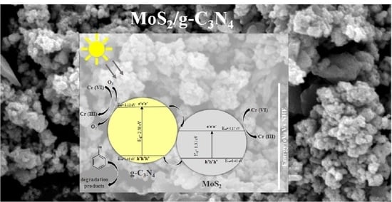
3.3. Photocatalytic Mechanism for the Composite Photocatalysts

Different photoinduced reactive species, such as hydroxyl radicals (OH·), superoxide radicals (O2) and holes (h+), may be involved in the photocatalytic process after electron–hole pairs are generated. Thus, photocatalytic experiments in the presence of isopropanol (IPA), superoxide dismutase (SOD) and triethanolamine (TEOA) were used to scavenge OH, O2 and h+, respectively, during the photodegradation of phenol in order to investigate the photocatalytic mechanism [3]. As shown in Table 5, the degradation rate constant (k) for phenol was 0.009 min−1 after exposure for 120 min under simulated sunlight without scavenger addition, and this changed after adding, IPA, SOD and TEOA, to 0.003, 0.004 and 0.002 min−1, respectively. It is clearly observed that the degradation of phenol was inhibited with the addition of scavengers, though TEOA was the most obvious. The degradation kinetics of phenol in the presence of scavengers are shown in Figure 7 and Table 5.
According to the above analysis, the proposed photocatalytic mechanism (Type II), involving the carrier transfer and photodegradation of phenol was illustrated as shown in Figure 8. The photogenerated electron–hole pairs were induced in the conduction band (CB) and valence band (VB) of g-C3N4 and MoS2 under irradiation. The photogenerated electrons transferred from the CB of g-C3N4 to that of MoS2, while holes moved from the VB of MoS2 to that of g-C3N4, leading the photogenerated electron–hole pair to be separated and transferred effectively. The holes (h+) in the VB of g-C3N4 participate in the degradation process. Simultaneously, electrons (e) in the CB together with H+ can reduce O2 to H2O2, which forms hydroxyl radicals. The e on the CB of g-C3N4 and MoS2 participates in the reduction of Cr(VI) to Cr(III). The proposed mechanism provides additional explanation for the better removal performance in the binary system. Regarding the reduction process, the electrons on MoS2 have weaker reduction ability; consequently they can reduce strong oxidation agents such as Cr(VI), enhancing the target reduction reaction without other reactions, such as O2 reduction. As far as the oxidation pathway is concerned, the enhancement is due to the better charge separation. The results of the present study indicate that the MoS2 could be a promising candidate as a non-noble metal co-catalyst for g-C3N4 photocatalysts. The composite catalysts can receive further applications either for degradation of pollutants or in energy conversion.

3.4. Recyclability of the Composite Photocatalysts

The stability of the prepared photocatalysts was investigated by examining the photocatalytic activity of the most efficient photocatalyst (1MoS2/g-C3N4) against oxidation of phenol in binary system for three continuous cycles (Figure 9). Reaction constants of phenol oxidation were 0.090, 0.089 and 0.083 min−1 for the first, second and third cycle, respectively (Table 6). A total loss of photocatalytic activity about 7.8% after the third photocatalytic cycle showed the sufficient stability of the catalyst considering also the possible losses of catalyst particles during the recovery process after each cycle. In addition, the catalyst separated at the end of the third catalytic cycle was characterized by XRD, SEM and ATR-FT-IR (Figure 10a–c), revealing a nearly identical pattern to the starting material.

4. Conclusions

In this work, mesoporous MoS2/g-C3N4 heterostructures were successfully synthesized via a two-step hydrothermal synthesis at various weight ratios (up to 10% w/w of MoS2) and assayed for the simultaneous oxidation of phenol and Cr(VI) reduction. Composite materials show higher photocatalytic activity under solar light in comparison with bare g-C3N4 and MoS2 for both oxidation and reduction processes, while the material with 1% MoS2 loading was found as the catalyst with the best efficiency. A considerable enhancement of the photocatalytic efficiency was observed for the binary system compared to the single component systems, indicating a promoting synergistic effect. The three cycling experiments indicated that the catalysts presented a good stability. Finally, type-II band alignment was proposed as the photocatalytic mechanism for the composed catalysts.

Author Contributions

Conceptualization, I.R. and I.K.; methodology, I.R. and I.K.; formal analysis, I.R. and F.B.; investigation, I.R. and I.K.; resources, I.K.; data curation, I.R.; writing—original draft preparation, I.R. and I.K.; writing—review and editing I.K., I.R. and F.B.; visualization, I.R.; supervision, I.K.; project administration, I.R.; funding acquisition, I.K. All authors have read and agreed to the published version of the manuscript.

Funding

This research received no external funding.

Institutional Review Board Statement

Not applicable.

Informed Consent Statement

Not applicable.

Data Availability Statement

Not applicable.

Acknowledgments

The authors acknowledge the access in XRD and SEM units of the University of Ioannina. The authors would like to thank D. Petrakis for the collaboration in the Laboratory of Industrial Chemistry, Dept. of Chemistry, University of Ioannina.

Conflicts of Interest

The authors declare no conflict of interest.

References

  1. Jiménez-Rangel, K.Y.; Lartundo-Rojas, L.; García-García, A.; Cipagauta-Díaz, S.; Mantilla, A.; Samaniego-Benítez, J.E. Hydrothermal Synthesis of a Two-Dimensional g-C3N4/MoS2/MnOOH Composite Material and Its Potential Application as Photocatalyst. J. Chem. Technol. Biotechnol. 2019, 94, 3447–3456. [Google Scholar] [CrossRef]
  2. Antonopoulou, M.; Giannakas, A.; Konstantinou, I. Simultaneous Photocatalytic Reduction of Cr(VI) and Oxidation of Benzoic Acid in Aqueous N-F-Codoped TiOsuspensions: Optimization and Modeling Using the Response Surface Methodology. Int. J. Photoenergy 2012, 1, 358–370. [Google Scholar] [CrossRef] [Green Version]
  3. Zhang, X.; Zhang, R.; Niu, S.; Zheng, J.; Guo, C. Enhanced Photo-Catalytic Performance by Effective Electron-Hole Separation for MoS2 Inlaying in g-C3N4 Hetero-Junction. Appl. Surf. Sci. 2019, 475, 355–362. [Google Scholar] [CrossRef]
  4. Cuerda-Correa, E.M.; Alexandre-Franco, M.F.; Fernández-González, C. Advanced Oxidation Processes for the Removal of Antibiotics from Water. An Overview. Water 2020, 12, 102. [Google Scholar] [CrossRef] [Green Version]
  5. Barrera-Díaz, C.; Cañizares, P.; Fernández, F.J.; Natividad, R.; Rodrigo, M.A.; Rosedal, E.; Toluca, E.; de México, M. Electrochemical Advanced Oxidation Processes: An Overview of the Current Applications to Actual Industrial Effluents. J. Mex. Chem. Soc. 2014, 58, 3. [Google Scholar] [CrossRef] [Green Version]
  6. Malato, S.; Fernández-Ibáñez, P.; Maldonado, M.I.; Blanco, J.; Gernjak, W. Decontamination and Disinfection of Water by Solar Photocatalysis: Recent Overview and Trends. Catal. Today 2009, 147, 1–59. [Google Scholar] [CrossRef]
  7. Zhang, G.; Zhang, J.; Zhang, M.; Wang, X. Polycondensation of Thiourea into Carbon Nitride Semiconductors as Visible Light Photocatalysts. J. Mater. Chem. 2012, 22, 8083–8091. [Google Scholar] [CrossRef]
  8. Bairamis, F.; Konstantinou, I. WO3 Fibers/g-C3N4 Z-Scheme Heterostructure Photocatalysts for Simultaneous Oxidation/Reduction of Phenol/Cr(VI) in Aquatic Media. Catalysts 2021, 11, 792. [Google Scholar] [CrossRef]
  9. Sun, K.; Jia, F.; Yang, B.; Lin, C.; Li, X.; Song, S. Synergistic Effect in the Reduction of Cr(VI) with Ag-MoS2 as Photocatalyst. Appl. Mater. Today 2020, 18, 100453. [Google Scholar] [CrossRef]
  10. Sun, H.; Wu, T.; Zhang, Y.; Ng, D.H.L.; Wang, G. Structure-Enhanced Removal of Cr(VI) in Aqueous Solutions Using MoS2 Ultrathin Nanosheets. New. J. Chem. 2018, 42, 9006–9015. [Google Scholar] [CrossRef]
  11. Wang, K.; Chen, P.; Nie, W.; Xu, Y.; Zhou, Y. Improved Photocatalytic Reduction of Cr(VI) by Molybdenum Disulfide Modified with Conjugated Polyvinyl Alcohol. Chem. Eng. J. 2019, 359, 1205–1214. [Google Scholar] [CrossRef]
  12. Fageria, P.; Sudharshan, K.Y.; Nazir, R.; Basu, M.; Pande, S. Decoration of MoS2 on g-C3N4 Surface for Efficient Hydrogen Evolution Reaction. Electrochim. Acta 2017, 258, 1273–1283. [Google Scholar] [CrossRef]
  13. Qi, Y.; Liang, Q.; Lv, R.; Shen, W.; Kang, F.; Huang, Z.H. Synthesis and Photocatalytic Activity of Mesoporous g-C3N4/MoS2 Hybrid Catalysts. R. Soc. Open Sci. 2018, 5, 180187. [Google Scholar] [CrossRef] [PubMed] [Green Version]
  14. Samy, O.; el Moutaouakil, A. A Review on MoS2 Energy Applications: Recent Developments and Challenges. Energies 2021, 14, 4568. [Google Scholar] [CrossRef]
  15. Mamba, G.; Mishra, A.K. Graphitic Carbon Nitride (g-C3N4) Nanocomposites: A New and Exciting Generation of Visible Light Driven Photocatalysts for Environmental Pollution Remediation. Appl. Catal. B Environ. 2016, 198, 347–377. [Google Scholar] [CrossRef]
  16. Zheng, D.; Zhang, G.; Hou, Y.; Wang, X. Layering MoS2 on Soft Hollow g-C3N4 Nanostructures for Photocatalytic Hydrogen Evolution. Appl. Catal. A Gen. 2016, 521, 2–8. [Google Scholar] [CrossRef]
  17. Huang, Q.; Liu, X.; Chen, Z.; Gong, S.; Huang, H. Surface Affinity Modulation of MoS2 by Hydrothermal Synthesis and Its Intermediary Function in Interfacial Chemistry. Chem. Phys. Lett. 2019, 730, 608–611. [Google Scholar] [CrossRef]
  18. Koutsouroubi, E.D.; Vamvasakis, I.; Papadas, I.T.; Drivas, C.; Choulis, S.A.; Kennou, S.; Armatas, G.S. Interface Engineering of MoS2-Modified Graphitic Carbon Nitride Nano-Photocatalysts for an Efficient Hydrogen Evolution Reaction. ChemPlusChem 2020, 85, 1379–1388. [Google Scholar] [CrossRef] [PubMed]
  19. Sivasankaran, R.P.; Rockstroh, N.; Kreyenschulte, C.R.; Bartling, S.; Lund, H.; Acharjya, A.; Junge, H.; Thomas, A.; Brückner, A. Influence of MoS2 on Activity and Stability of Carbon Nitride in Photocatalytic Hydrogen Production. Catalysts 2019, 9, 695. [Google Scholar] [CrossRef] [Green Version]
  20. Wei, H.; Zhang, Q.; Zhang, Y.; Yang, Z.; Zhu, A.; Dionysiou, D.D. Enhancement of the Cr(VI) Adsorption and Photocatalytic Reduction Activity of g-C3N4 by Hydrothermal Treatment in HNO3 Aqueous Solution. Appl. Catal. A Gen. 2016, 521, 9–18. [Google Scholar] [CrossRef]
  21. Tian, Y.; Ge, L.; Wang, K.; Chai, Y. Synthesis of Novel MoS2/g-C3N4 Heterojunction Photocatalysts with Enhanced Hydrogen Evolution Activity. Mater. Charact. 2014, 87, 70–73. [Google Scholar] [CrossRef]
  22. Visic, B.; Dominko, R.; Gunde, M.K.; Hauptman, N.; Skapin, S.D.; Remskar, M. Optical Properties of Exfoliated MoS2 Coaxial Nanotubes—Analogues of Graphene. Nanoscale Res. Lett. 2011, 6, 593. [Google Scholar] [CrossRef] [PubMed] [Green Version]
  23. Hu, K.H.; Hu, X.G.; Wang, J.; Xu, Y.F.; Han, C.L. Tribological Properties of MoS2 with Different Morphologies in High-Density Polyethylene. Tribol. Lett. 2012, 47, 79–90. [Google Scholar] [CrossRef]
  24. Konstas, P.S.; Konstantinou, I.; Petrakis, D.; Albanis, T. Synthesis, Characterization of g-C3N4/SrTiO3 Heterojunctions and Photocatalytic Activity for Organic Pollutants Degradation. Catalysts 2018, 8, 554. [Google Scholar] [CrossRef] [Green Version]
  25. Amini, M.; Ahmad Ramazani, S.A.; Faghihi, M.; Fattahpour, S. Preparation of Nanostructured and Nanosheets of MoS2 Oxide Using Oxidation Method. Ultrason. Sonochem. 2017, 39, 188–196. [Google Scholar] [CrossRef]
  26. Zhang, X.; Suo, H.; Zhang, R.; Niu, S.; Zhao, X.; Zheng, J.; Guo, C. Photocatalytic Activity of 3D Flower-like MoS2 Hemispheres. Mater. Res. Bull. 2018, 100, 249–253. [Google Scholar] [CrossRef]
  27. Thommes, M.; Kaneko, K.; Neimark, A.V.; Olivier, J.P.; Rodriguez-Reinoso, F.; Rouquerol, J.; Sing, K.S.W. Physisorption of Gases, with Special Reference to the Evaluation of Surface Area and Pore Size Distribution (IUPAC Technical Report). Pure Appl. Chem. 2015, 87, 1051–1069. [Google Scholar] [CrossRef] [Green Version]
  28. Li, J.; Liu, E.; Ma, Y.; Hu, X.; Wan, J.; Sun, L.; Fan, J. Synthesis of MoS2/g-C3N4 Nanosheets as 2D Heterojunction Photocatalysts with Enhanced Visible Light Activity. Appl. Surf. Sci. 2016, 364, 694–702. [Google Scholar] [CrossRef]
  29. Barrera-Díaz, C.E.; Lugo-Lugo, V.; Bilyeu, B. A Review of Chemical, Electrochemical and Biological Methods for Aqueous Cr(VI) Reduction. J. Hazard. Mater. 2012, 224, 1–12. [Google Scholar] [CrossRef]
  30. Du, X.; Yi, X.; Wang, P.; Deng, J.; Wang, C.C. Enhanced Photocatalytic Cr(VI) Reduction and Diclofenac Sodium Degradation under Simulated Sunlight Irradiation over MIL-100(Fe)/g-C3N4 Heterojunctions. Cuihua Xuebao/Chin. J. Catal. 2019, 40, 70–79. [Google Scholar] [CrossRef]
Figure 1. XRD patterns of (a) g-C3N4, MoS2, (b) composite catalysts.
Photochem 01 00023 g001
Figure 2. ATR-FT-IR spectra of (a) g-C3N4, MoS2, (b) composite catalysts.
Photochem 01 00023 g002
Figure 3. SEM images of (a) g-C3N4, (b) MoS2 and (c) 1MoS2/g-C3N4 and (d) 10MoS2/g-C3N4.
Photochem 01 00023 g003
Figure 4. Nitrogen adsorption–desorption isotherms and pore size distributions for g-C3N4, MoS2, 1MoS2/g-C3N4, 3MoS2/g-C3N4.
Photochem 01 00023 g004
Figure 5. (a) UV–Vis absorption spectra of prepared catalysts, (b) Kübelka–Munk plots for g-C3N4, MoS2 and 1MoS2/g-C3N4 for indirect band gap semiconductors.
Photochem 01 00023 g005
Figure 6. Photocatalytic degradation kinetics of (a) phenol in single system, (b) phenol and (c) Cr(VI) in binary system under solar light irradiation.
Photochem 01 00023 g006
Figure 7. Photocatalytic degradation kinetics of phenol in single system in the presence of scavengers and 1MoS2/g-C3N4 photocatalyst under solar light irradiation.
Photochem 01 00023 g007
Figure 8. Schematic illustration of carrier transfer in the MoS2/g-C3N4 heterojunction.
Photochem 01 00023 g008
Figure 9. Reusability performance of 1MoS2/g-C3N4 photocatalyst for three continuous cycles.
Photochem 01 00023 g009
Figure 10. (a) SEM image, (b) XRD pattern, (c) ATR-FT-IR spectra of 1MoS2/g-C3N4 photocatalyst after the third photocatalyst cycle.
Photochem 01 00023 g010
Table 1. Specific surface area, average pore diameter and total pore volume of prepared catalysts.
CatalystSpecific Surface Area SBET
(m2g−1)
Average Pore Diameter
(nm)
VTOT
(cm3 g−1)
MoS22.0310.016
g-C3N481.38.30.169
0.5% MoS2/g-C3N493.710.20.238
1% MoS2/g-C3N462.29.50.148
3% MoS2/g-C3N490.210.90.245
10% MoS2/g-C3N492.110.50.239
Table 2. Energy band gap and absorption edge of prepared catalysts.
CatalystEnergy Band Gap (eV)Absorption Edge λ (nm)
g-C3N42.58480
MoS21.31946
0.5% MoS2/g-C3N42.56484
1% MoS2/g-C3N42.66466
3% MoS2/g-C3N42.64469
10% MoS2/g-C3N42.64469
Table 3. Kinetic parameters (first-order kinetic constants (k), half-life (t1/2) and correlation coefficients (R2) of phenol in single system.
Catalystk (min−1)t1/2 (min)R2
g-C3N40.02231.50.9401
MoS20.00023465.00.5016
0.5MoS2/g-C3N40.006116.00.9528
1MoS2/g-C3N40.00977.00.9940
3MoS2/g-C3N40.005139.00.9250
10MoS2/g-C3N40.006116.00.9158
Table 4. Kinetic parameters (first-order kinetic constants (k), half-life (t1/2) and correlation coefficients (R2)) of phenol and Cr(VI) in binary system.
Binary Phenol Cr(VI)
Catalystk (min−1)t1/2 (min)R2k (min−1)t1/2 (min)R2
g-C3N40.06810.20.99780.003231.00.9477
MoS20.002346.50.93730.002346.50.9694
0.5MoS2/g-C3N40.04216.50.97380.002346.50.9552
1MoS2/g-C3N40.0917.60.92460.003231.00.9740
3MoS2/g-C3N40.04216.50.95130.002346.50.9478
10MoS2/g-C3N40.03122.40.93740.003231.00.9325
Table 5. Kinetic parameters (first-order kinetic constants (k), half-life (t1/2) and correlation coefficients (R2)) of phenol in scavenging experiments.
Scavengerk (min−1)t1/2 (min)R2
IPA0.0032310.9742
SOD0.004173.20.9590
TEOA0.002346.50.9553
no scavenger0.00977.00.9940
Table 6. Kinetic parameters (first-order kinetic constants (k), half-life (t1/2) and correlation coefficients (R2)) of phenol degradation by 1MoS2/g-C3N4 catalyst after three consecutive cycles.
Cyclek (min−1)t1/2 (min)R2
10.097.70.9510
20.0897.80.9453
30.0838.30.9496
Publisher’s Note: MDPI stays neutral with regard to jurisdictional claims in published maps and institutional affiliations.

