
The Stone Skeleton: A Reappraisal

1
Department of Architectural Engineering, Penn State University, University Park, PA 16802, USA
2
Department of Civil and Environmental Engineering (DICA), Politecnico di Milano, 20133 Milan, Italy
*
Author to whom correspondence should be addressed.
Heritage 2024, 7(5), 2265-2276; https://doi.org/10.3390/heritage7050107
Submission received: 24 March 2024
/
Revised: 22 April 2024
/
Accepted: 23 April 2024
/
Published: 26 April 2024
(This article belongs to the Section Architectural Heritage)
Abstract
:Jacques Heyman’s 1966 article “The Stone Skeleton” has been influential in the assessment of masonry arches in general, including masonry bridges and gothic architecture. Heyman’s article relies on limiting assumptions about arch behavior, and concludes that an arch can be declared stable based on the location of a statically admissible thrust line within the arch. In the following commentary, we assess the validity of the assumptions made by Heyman and the uses that have been made of his application of the lower bound theorem of plasticity. We conclude that Heyman’s methods have enduring value, but that the user needs to recognize the limitations of the assumptions made and the limits on the validity of conclusions imposed by these assumptions.
1. Introduction
Jacques Heyman’s 1966 Article “The Stone Skeleton” is frequently cited at the beginning of articles on the assessment of masonry arches, including bridge arches and the arches used in ancient architecture [1]. The limit analysis theorems, described in Heyman’s paper for the analysis of masonry arches, are still widely applied to the analysis of heritage structures. This form of analysis is very useful for determining reasonable bounds on behavior or for estimating the capacity of a structure. However, the simplifying assumptions adopted by Heyman and some of the effects in masonry structures that he has ruled out by assumption require that these methods for the analysis of arches be modified, elaborated, and sometimes corrected when analyzing real masonry structures. It can also be argued that many contemporary researchers overlook important effects in masonry arch analysis by focusing strictly on the type of limit analysis that Heyman considered.
The Stone Skeleton is an application of the theorems of plastic collapse. Heyman noted that masonry arches, similarly to steel frames, develop hinges under loading, and that their limit state is the formation of one hinge more than the degree of statical indeterminacy. In this observation, Heyman followed Kooharian [2], although he expanded greatly on Kooharian’s findings. Heyman’s method, spurred on by a growing interest in the analysis of ancient structures, has been used extensively in the analysis of masonry structures built prior to 1900. Computer programs incorporating the principles of plastic analysis have been written and distributed (LimitState:RING [3] and Archie-M [4]), and the method has been widely employed in the assessment of masonry arch bridges [5]. Some of these programs, such as LimitState:RING, incorporate failure modes beyond the hinging mechanism described by Heyman.
2. Heyman’s Version of the Lower Bound and Upper Bound Theorems
In describing plasticity in steel structures, Neal and Symonds state a lower bound theorem and an upper bound theorem that depend on proportional loading and the search for a collapse load factor [6]. In “The Stone Skeleton”, Heyman’s analysis of elements of gothic architecture depends on the lower bound, or safe, theorem of plasticity, as shown in his statement, “if a line of thrust can be found which is in equilibrium with the external loads and which lies wholly within the masonry, then the structure is safe”. This viewpoint of the lower bound theorem does not depend on proportional loading, or any external loading, but only on the self-weight and the shape of the structure.
Boothby and Brown (1992) have identified the lower and upper bound theorems of plasticity with criteria for the stability of an arch, used in the context of unreinforced masonry assemblies [7], and so we will continue to describe the theorems of plasticity as stability criteria. Following Heyman, a lower bound on stability can be stated without recourse to proportional loading:
If, for a given loading, a statically admissible thrust line can be found that is entirely within the arch ring (that is, |M/N| ≤ t/2), then the arch is stable under those loads. In this statement, M is the internal bending moment, N is the internal axial force and t is the thickness of the arch ring. The stability condition can also be represented as “a line of thrust…wholly within the masonry”, and an upper bound on stability:
If, for a given loading on an arch, a kinematically admissible mechanism can be found for which the instantaneous work is less than 0, then the arch is unstable under those loads.
3. The Lasting Contributions of Heyman’s Method
Before the application of plasticity methods to the analysis of unreinforced masonry arches, there was a reliance on the “middle 1/3 rule”. That is that the thrust line of an arch must remain within the middle 1/3 to ensure the safety of the arch. In fact, as Heyman discussed, an excursion of the thrust line outside of the middle 1/3 causes neither a local failure nor a global failure of the arch. It simply indicates a migration of the compression zone towards the edge of the arch. For a voussoir with a notionally unlimited compressive capacity, the compression zone can extend to the face of the arch.
After its publication, Heyman’s method became the principal legitimate means of analyzing an arch available to most engineers. Although there are many previously published elastic methods, both analytical and graphical, they all require tedious calculations, and all depend on locating the thrust line in the middle third of the arch. The “middle third rule” is an unnecessary restriction that limits the apparent capacity of an arch, and does not explain why so many examples of arches still stand with a thrust line outside of the middle third. Heyman’s methods found instant applicability in the analysis of gothic architecture, and allowed the profession to make sense out of many of the pre-rational techniques and conceptions of medieval architecture.
4. Elaborations on Heyman’s Methods
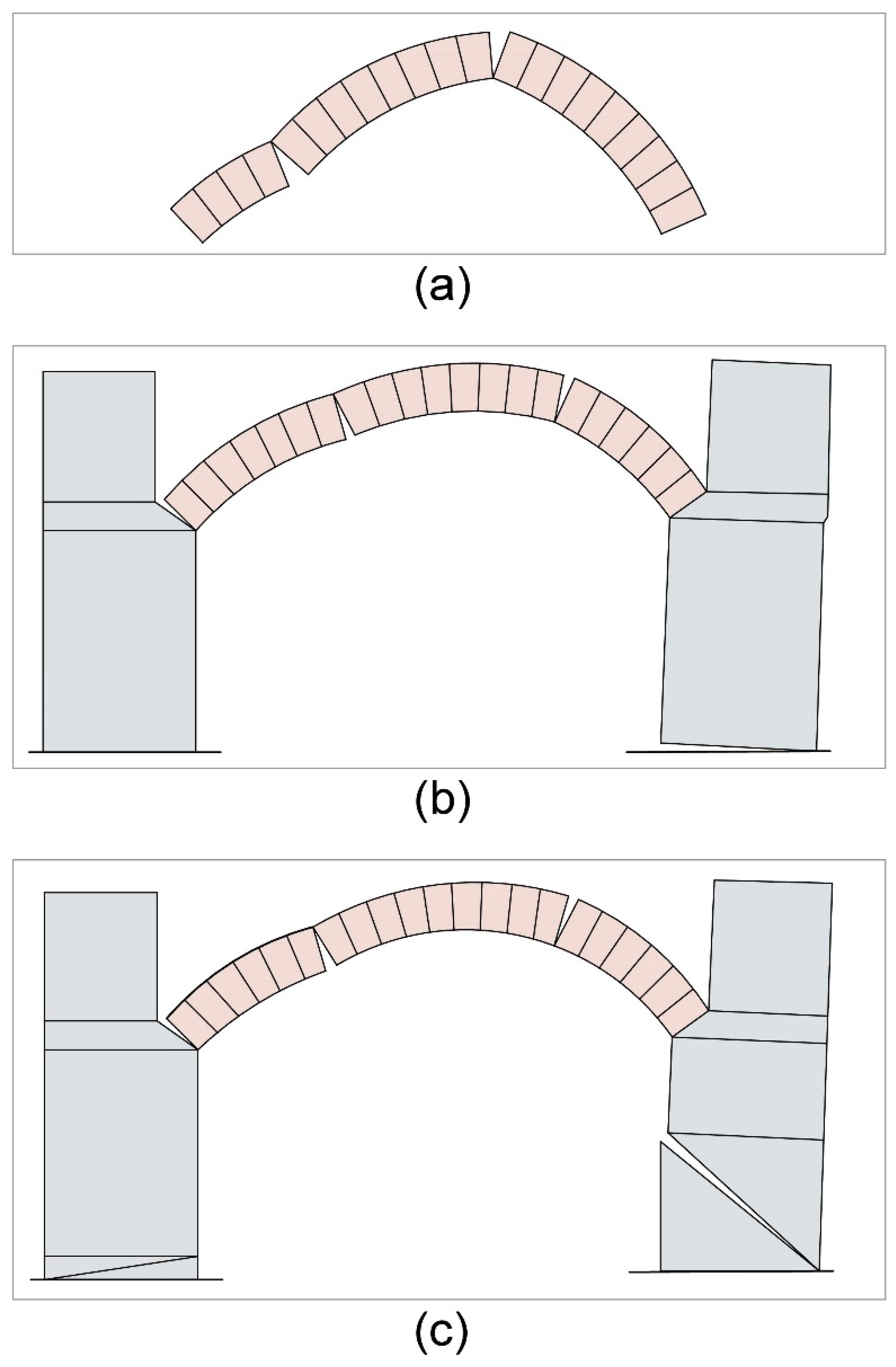
Ochsendorf, Hernando, and Huerta (2004) and Ochsendorf (2005) investigated the strength of buttresses in general [8,9]. They also analyzed an arch bridge supported by a yielding abutment in terms of upper bound analysis based on the Heyman assumptions given above. This investigation can be conducted by considering the abutment movement in the general kinematics of the failure of the arch (Figure 1). So, where four hinges alternating between the intrados and the extrados may define a collapse mechanism for an arch, the lateral movement of one of the supports and three hinges may constitute a collapse mechanism with a lower collapse load. The determination of the instantaneous center of the mechanism is similar in both cases. Zampieri, Amoroso, and Pellegrino [10] describe the failure of arches with yielding abutments or support settlements in terms of virtual work applied to upper bound collapse mechanisms. The yielding of the abutment was considered, in a similar framework, much earlier by Franciosi [11].
In addition to abutment movements, the possibility of sliding between the blocks has been incorporated into upper and lower bound analysis by Livesley [12,13] and by Boothby [14]. The plasticity analysis of masonry structures has also been extended to plastic shakedown analysis by considering the deformable plastic character of joints made of sand-lime mortar [15].
5. Limit Analysis Assumptions
Heyman’s analysis is based on three assumptions:
- Masonry has no tensile capacity;
- Masonry has unlimited compressive capacity;
- Masonry units do not slide with respect to each other (effectively, unlimited shear capacity).
In consequence of these assumptions, two adjacent stones can only “hinge”, with compression on one face (intrados or extrados), opening with zero stress on the other.
The “no tensile capacity” claim is a conservative assumption, although not always a realistic one. Fanning and Boothby [16] and Boothby and Fanning [17] noted that, to ensure the fidelity of the results of a masonry arch analysis, it is necessary to choose a small value of tensile capacity in the model used to replicate the behavior of a masonry arch bridge. Unlimited compressive capacity, and unlimited shear capacity, effectively mean that the crushing/sliding of the stones is not a significant factor in arch failure. Heyman justifies the second assumption by noting that stresses in masonry structures are far less intense than the compressive capacity; however, in the formation of a hinge, the compressive stress in the masonry becomes very large as the area resisting compressive force shrinks. Heyman does observe that “local spalling at the pressure points may sometimes be seen, but these are not signs of overall danger” [18]. However, the images in Figure 2 of a colonette at Milan Cathedral and a flying buttress at Reims cathedral show instances where the compressive stress may be a sign of overall danger. The compressive stresses within a masonry pier, arch or buttress may precipitate a failure by causing a compression failure in the material via compressive stress at a hinge. Figure 3 shows a vault rib at the Cathedral of Milan, where a critical failure has occurred in the material at the base of a masonry arch. The failure mode is complicated, but the hinging of the arch is accompanied by a shear failure. A plan of the Cathedral in Figure 4 shows the location of the defects depicted in Figure 2a, Figure 3, Figure 5 and Figure 6.
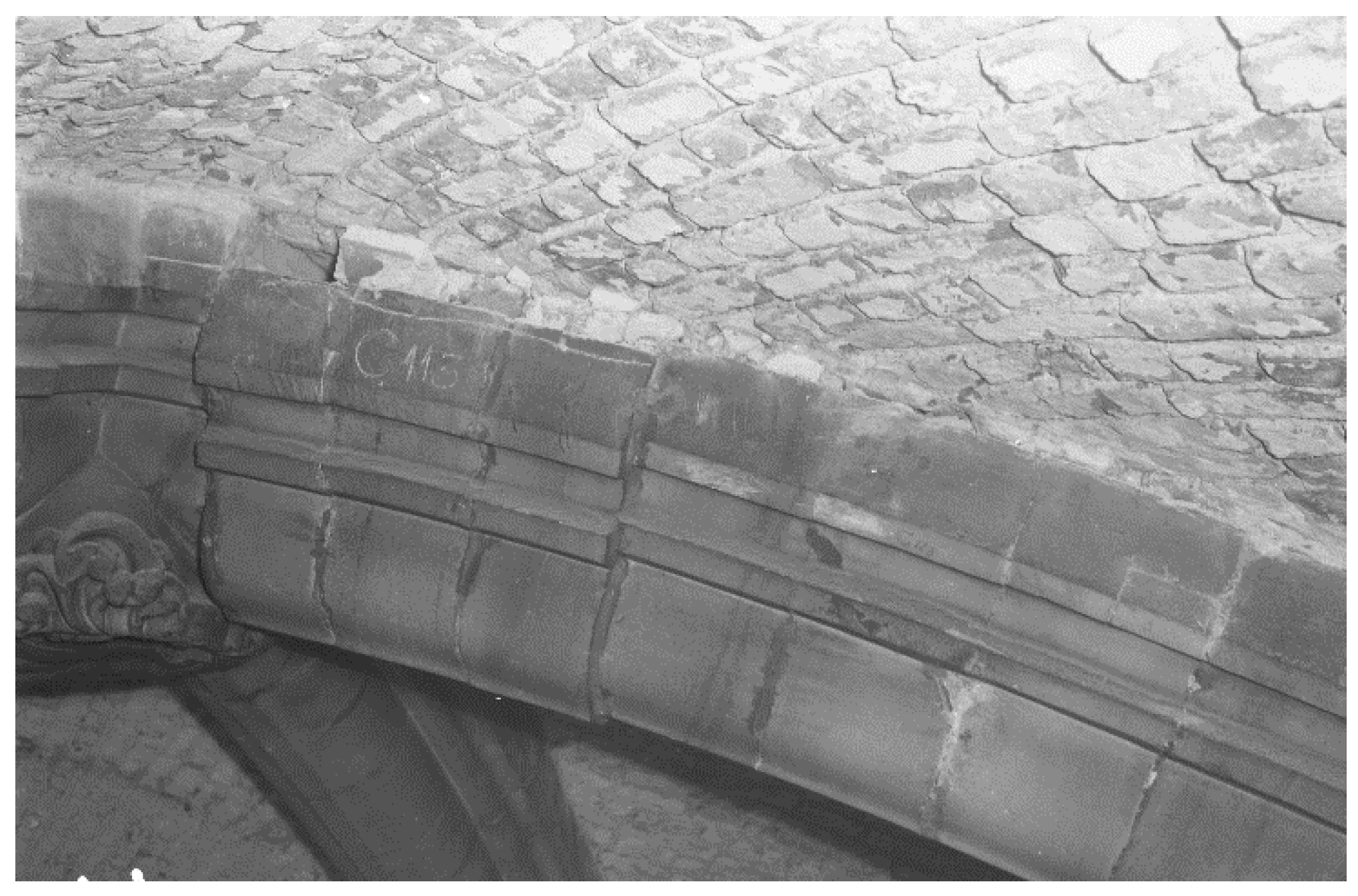
One can also note, in any study of actual failures of bridge or building arches, that the sliding of voussoirs, bricks, or portions of the arch occurs too commonly to be ruled out by assumption. Figure 5a,b show the sliding of the blocks in an arch, also at Milan Cathedral. The plastic theory of masonry can be adapted to account for such sliding, as described above. For relatively low span-rise ratios and relatively thick arches, it is often necessary to consider this failure mode. A flat arch, for instance, is locked against a hinging mode and can only fail by sliding. Also from the Cathedral of Milan, Figure 6 shows the sliding of a voussoir in a diagonal arch rib [19]. In this case, as in many other instances, this sliding was partly the result of the abutment yielding.
6. What Plasticity Approaches to Unreinforced Structural Masonry May Be Missing
The elements of unreinforced masonry structures that are not modeled in Heyman’s analysis can be grouped into material behavior and structural behavior. The material behavior elements that we will consider are tensile capacity, compressive capacity, and creep. The structural behaviors of interest are failure modes beyond the classical four-hinged arch failure: creep instability, shear failure, compressive failure, or others.
There are some other types of structural actions that are excluded from the simple application of the plasticity approach to masonry structures. The most notable are foundation movements (beyond a simple self-limiting settlement that is accommodated by hinges in the arch), creep, cracking tensile capacity, and the influence of other parts of the structure, such as spandrel walls, fill, and haunching. Heyman’s justification for ignoring compressive failure in the masonry is discussed above.
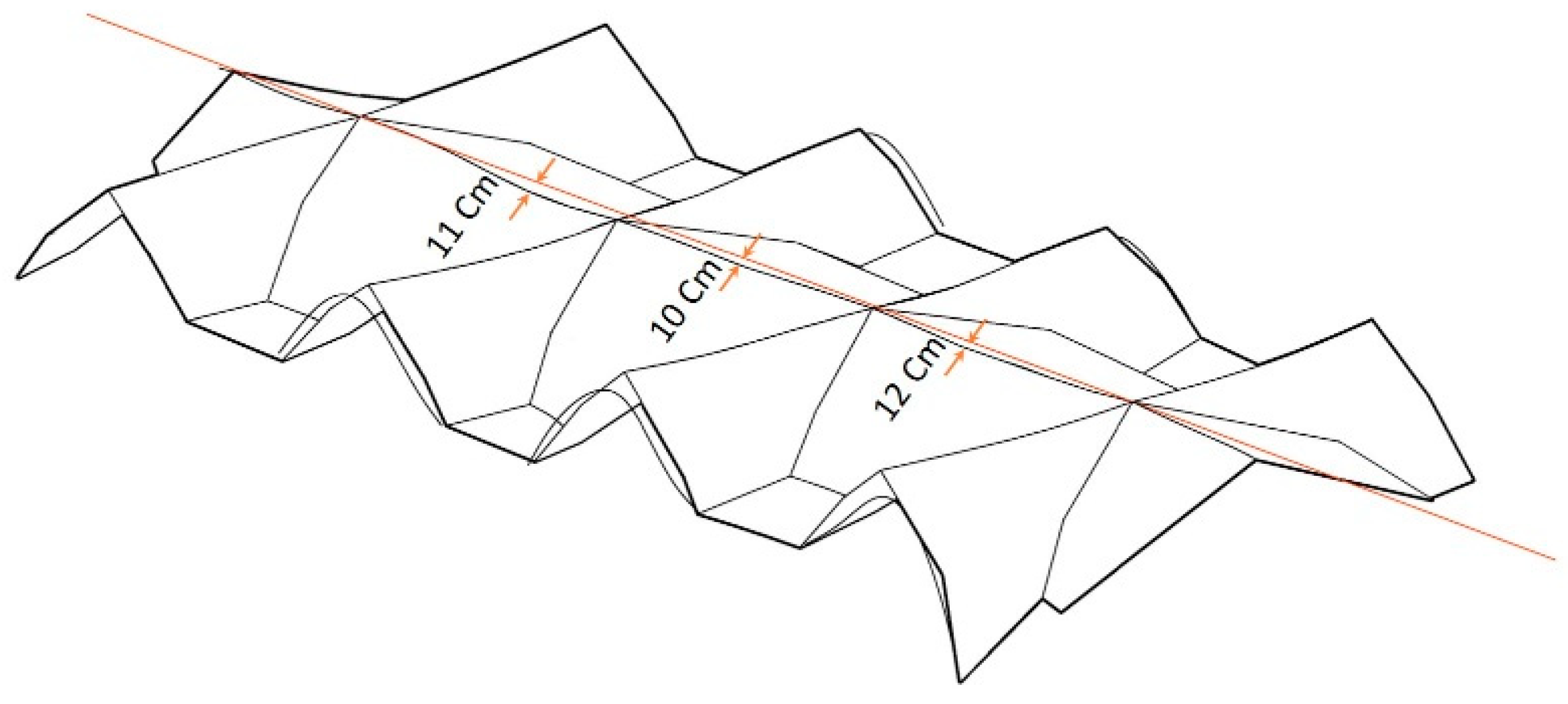
Issues of creep, although noted by Heyman, do not really find a place in his form of analysis [20]. Creep of masonry has had a destabilizing influence on many structures from the Gothic era, although it is often difficult to separate creep from the yielding of the foundation under abutments or piers. Beverley Minster, for instance, has vaults that are noticeably sagging, in some cases by over 10 cm (Figure 7). This appears to be the result of a combined action of the rotation of the buttresses due to foundation conditions and creep within the fabric. The figure, from a survey taken above the vaults in 2008, describes the sagging of the nave vaults. Although it is true that creep stresses have no influence on the plastic capacity of a single hinge, creep cannot be dismissed as having no influence on capacity where a change in geometry is the result of the creep of a structure. The weakening of buttresses due to the creep of the vaults is described by Ochsendorf [9], although as a problem in limit analysis, without specific reference to the expected magnitude of the creep.
In the apse of the church of San Bassiano (Figure 8), a pattern of radial cracks has developed in the vault. The eventual failure of this structure would most likely be a combined result of cracking in the masonry, the subsequent modification of the load paths through the masonry, and the exacerbation of the cracks.
Heyman [18] and others have described how, in finding an alternative load path that satisfies the lower bound condition, a pattern of cracking can be considered harmless. The examples that he cites are the “Sabouret cracks” in a Gothic vault, cracks along the axis of the nave in line with the upper nave walls, and the meridional cracking in the dome of St. Peter’s examined by Poleni [21]. In reality, cracks in masonry structures are rarely harmless, and may propagate or grow larger, even if there are alternate load paths.
Figure 8.
Apse dome at San Bassiano (a) from inside and (b) from outside; Cardani and Massetti [22].
Figure 8.
Apse dome at San Bassiano (a) from inside and (b) from outside; Cardani and Massetti [22].

This damage in a vault or dome may also interact unfavorably with creep in the masonry or the settlement of the supports of the structures under investigation. In view of the foregoing, Heyman’s discussion of the stability through time of a historic masonry structure after its construction may be extended to include explicit discussions of masonry creep and foundation settlement.
On the other hand, even a very small permissible tensile strength within the masonry may have a significant effect on the capacity of the structure. A previous study of bridges [23] concluded that an increase in the collapse load by a factor of 2 may result from the selection of a tensile strength of 0.5 N/mm2 or less. Fanning and Boothby concluded similarly that the inclusion of a tensile strength of 0.5 MPa or less is required for fidelity to the results from testing [16]. The same is probably true for the accuracy of models used to study buildings. Studies performed via diagonal compression tests on square specimens extracted from historic masonry buildings have found a significant tensile stress capacity of the building fabric [24].
7. Continuing Reliance on Heyman’s Methods
Over 50 years after the publication of The Stone Skeleton, there have been many more studies of medieval masonry architecture, and significantly more failure modes of masonry arches have been noted beyond the four-hinged arch mechanisms described by Heyman. Heyman’s method clearly has enduring utility in establishing the bounds or approximate values of the strength of an arch. However, as an assessment tool, this method in general needs to be supplemented with a more realistic treatment of the capacity of an arch. Heyman’s method, however, often seems to be used to the exclusion of other methods, sometimes out of a lack of understanding of the other possible parameters. A brief look at some of the present-day literature, as presented in the paragraph below, shows that limit analysis, often two-dimensional limit analysis, considering hinging only continues in many cases to be used as a primary tool for the analysis of masonry arches, for the assessment of masonry arch bridges, for the assessment of masonry heritage buildings, and for the review of repairs to masonry arches. There is, of course, nothing wrong with this, if the analyst recognizes fully the limitations of these methods, and is prepared to modify the assumptions used in this analysis and to bring other methods to bear on some of the factors overlooked in this analysis.
The analysis of arches with yielding abutments essentially began with Ochsendorf’s dissertation [9]. This is an original work on the application of theorems of plastic collapse to arches on spreading supports and the buttressing force required to resist this spreading. Only hinging mechanisms are considered. His section on future works describes a further need for investigations of sliding failures of the buttress, but not the arch. Ochsendorf carried out further investigations of hinging mechanisms in structures with failing abutments in [8]. The approach of looking at abutment failures combined with strictly hinging mechanisms of arch collapse has continued to be applied since that time. Morer et al. [26] and Riveiro et al. [27], in looking at a complex, often rebuilt, multispan stone arch bridge, used Lidar scanning to determine the geometry of the bridge, and then applied a computer implementation of hinging analysis as their means of determining the capacity of the bridge. Given the two-dimensional nature of this analysis and the lack of accounting for other effects such as actual vehicle configurations, material failure, cracking, sliding, and settlement, this analysis would have to be considered incomplete. Galassi et al. [28], in looking at failure mechanisms on moving supports, considered only hinging mechanisms on unloaded voussoirs without spandrel walls. Galassi showed settling arches as developing hinging mechanisms exclusively [29]. Zampieri, Amoroso, and Pellegrino [10] and Zampieri, Cavalagli, Gusella, Pellegrino [30] offer similar studies of support settlement in arches that only consider hinging mechanisms.
As the above summary indicates, the analysis of arches with yielding abutments focuses on the mechanisms of an arch with abutment displacement, either horizontal or vertical, subject to the standard assumptions of no compression failure, no tensile stress, and no sliding. Continuing through the present time, a variety of authors invoke these assumptions in the investigation of the effects of abutment movements, and refer to Ochsendorf’s or similar experiments showing the result of such abutment movement to be the formation of a three-hinged mechanism in the arch.
Any arch with a spandrel wall above is likely to fail in a very different manner. The additional weight of masonry above the arch, applied at the same time to a larger portion of the back of the arch, is very likely to cause the upper part of the arch to fall in a wedge-like failure mode as the abutments of the arch spread. The propensity for this type of failure cannot be described effectively in energy or limit state terms because the frictional force between voussoirs increases in proportion to the weight of the segment of the arch that is subject to sliding. Nevertheless, this type of failure of an arch is common, as shown in the images in Figure 10.
In the above discussion, we have looked at examples of the analysis of structures with spreading, yielding, or sinking supports, where one would expect to find sliding blocks, out of plane, fill, and other effects. This critique can be extended to the seismic analysis of masonry bridges, where, for instance Breccolotti et al. [31] proposed a method for the seismic analysis of masonry arch bridges that considers only in-plane hinging mechanisms, omitting sliding mechanisms, abutment failure, and transverse failure. Zampieri et al. [32] considered the transverse loading of multi-span high pier masonry bridges, but the analysis focused on hinging mechanisms resulting from such transverse loading. DeLorenzis, DeJong, and Ochsendorf [33] applied rigid block theory, with assumptions intact, to the analysis of impulsive dynamic response, including the exclusive hinging mechanism response of the system to base motion. In a seismic event, the failure of an arch bridge in the transverse direction is much more likely than failure in the direction along the axis of the bridge, and the separation at joints and the spreading of supports make classic hinging mechanisms less likely.
Because sliding failure is a common failure mode, especially for low-rise arches, the “no sliding” assumption is overly restrictive at best, and misleading at worst. Although arches with spreading supports may fail by hinging when the bare arch ring is considered (except in some of the cases investigated by Rios et al. [34]), the universal presence of a wall above the arch ring often shifts the failure mode to an internal sliding in the arch under yielding abutments. A comprehensive explanation for this frequently occurring sliding mechanism is not yet available, and a continuing focus on limit analysis methods may not produce an explanation for this failure mode.
8. Conclusions
Limit analysis, as proposed by Heyman [1], has proven to be an enduring and robust method for the analysis of load-bearing masonry structures in general, especially arches and vaults. Its primary value is as a means of obtaining initial results or as a means of checking results obtained by more comprehensive methods. Anyone using this form of analysis should carefully consider the factors that are omitted from most forms of limit analysis for masonry. Among these omissions are the influence of a small tensile capacity in the masonry and the influence of the spandrel walls or backing masonry, which may cause an underestimate of the capacity of the structure. There are also significant factors that may cause an overestimate of the capacity of an unreinforced masonry structure, such as the influence of the crushing of the masonry at a hinge, the possibility of sliding at joints in the masonry, and the influence of creep. A structure may be found by limit analysis to be stable after the development of cracks, where there are alternate load paths available. However, the unchecked growth of cracks creates significant maintenance issues, and may ultimately precipitate the collapse of the structure. The application of limit analysis methods to structures subject to creep may be misleading. Although the plastic capacity of masonry is not influenced by creep stresses, creep effects, especially combined with foundation settlement, may precipitate the collapse of a structure. An example of possible over-reliance on the customary assumptions of limit analysis for arches is furnished by the analysis of the effects of support movement on arches. Such analysis has usually included the “no sliding” assumption, and some of the experiments performed on this failure mode have been biased towards this assumption. In fact, the presence of loads above the arch ring and other factors frequently causes low-rise arches with yielding abutments to fail by sliding.
Author Contributions
All authors contributed equally to this commentary, including conception, writing, and editing. All authors have read and agreed to the published version of the manuscript.
Funding
This research received no external funding.
Data Availability Statement
The survey data of the vaults at Beverley Minster described in the article are available from the corresponding author on reasonable request.
Acknowledgments
All photographs of Milan Cathedral are courtesy of Veneranda Fabbrica del Duomo di Milano. Figure 1 has been used by permission from the Journal of Architectural Engineering and redrawn by Maria Chiara Giangregorio. The photograph in Figure 2b was received from its author, Grigor Angjeliu. Figure 7 was drawn by Mina Savaroliya. Figure 9 has been used by permission from the referenced source. The photograph in Figure 10 was received from its author, Romolo di Francesco.
Conflicts of Interest
The authors declare no conflicts of interest.
References
- Heyman, J. The stone skeleton. Int. J. Solids Struct. 1966, 2, 249–279. [Google Scholar] [CrossRef]
- Kooharian, A. Limit analysis of voussoir (segmental) and concrete arches. J. Am. Concr. Inst. 1952, 24, 317–328. [Google Scholar]
- LimitState: Ring. 2022. Available online: https://www.limitstate.com/ring (accessed on 8 February 2022).
- Archie-M. 2022. Available online: http://www.obvis.com/archie-m/ (accessed on 8 February 2022).
- Gilbert, M.; Cole, G.; Smith, C.; Melbourne, C. Guidance on the Assessment of Masonry Arch Bridges; Civil Infrastructure Initiative: London, UK, 2022. [Google Scholar]
- Neal, B.G.; Symonds, P.S. Rapid calculation of collapse loads for framed steel structures. Proc. Inst. Civ. Eng. 1952, 3, 58–71. [Google Scholar]
- Boothby, T.E.; Brown, C.B. Stability of masonry piers and arches. J. Eng. Mech. 1992, 118, 367–383. [Google Scholar] [CrossRef]
- Ochsendorf, J.; Hernando, J.I.; Huerta, S. Collapse of masonry buttresses. J. Archit. Eng. 2004, 10, 88–97. [Google Scholar] [CrossRef]
- Ochsendorf, J.A. Collapse of Masonry Structures. Ph.D. Thesis, University of Cambridge, Cambridge, UK, 2005. [Google Scholar]
- Zampieri, P.; Amoroso, M.; Pellegrino, C. The masonry buttressed arch on spreading support. Structures 2019, 20, 226–236. [Google Scholar] [CrossRef]
- Franciosi, C. Limit behaviour of masonry arches in the presence of finite displacements. Int. J. Mech. Sci. 1986, 28, 463–471. [Google Scholar] [CrossRef]
- Livesley, R.K. Limit analysis of structures formed from rigid blocks. Int. J. Numer. Methods Eng. 1978, 12, 1853–1871. [Google Scholar] [CrossRef]
- Livesley, R.K. A computational model for the limit analysis of three-dimensional masonry structures. Mecccanica 1992, 27, 161–172. [Google Scholar] [CrossRef]
- Boothby, T.E.; Thomas, E. Stability of Masonry Piers and Arches Including Sliding. J. Eng. Mech. 1994, 120, 304–319. [Google Scholar] [CrossRef]
- Boothby, T.E.; Rosson, B.T. Elasto-Plastic Hardening and Shakedown of Masonry Arch Joints. Meccanica 1999, 34, 71–84. [Google Scholar] [CrossRef]
- Fanning, P.J.; Boothby, T.E. Three dimensional modelling and full-scale testing of masonry arch bridges. Comput. Struct. 2001, 79, 2645–2662. [Google Scholar] [CrossRef]
- Boothby, T.E.; Fanning, P.J. Load rating of masonry arch bridges: Refinements. J. Bridge Eng. 2004, 9, 304–307. [Google Scholar] [CrossRef]
- Heyman, J. The collapse of stone vaulting. Trans. Built Environ. 1993, 4, 12. [Google Scholar]
- Angjeliu, G.; Cardani, G.; Coronelli, D.; Boothby, T. Modelling and safety assessment of observed sliding damage in a masonry rib vault. J. Cult. Herit. 2023, 59, 264–273. [Google Scholar] [CrossRef]
- Heyman, J. The Stone Skeleton; Cambridge University Press: New York, NY, USA, 1995. [Google Scholar]
- Heyman, J. Poleni’s Problem. Proc. Inst. Civ. Eng. 1988, 84, 737–759. [Google Scholar] [CrossRef]
- Cardani, G.; Massetti, G.E. When the strengthening of historic maonsry buildings should be carried out in different phases: The structural reinforcment and monitoring of the Lombard-Romanesque church of Saint Bassiano in in Pizzighetone (CR), Italy. In Proceedings of the Third International Conference on Protection of Historical Constructions, Lisbon, Portugal, 12–15 July 2017. [Google Scholar]
- Ng, K.H.; Fairfield, C.A.; Sibbald, A. Finite element analysis of masonry arch bridges. Proc. Inst. Civ. Eng. Struct. Build. 1999, 134, 119–127. [Google Scholar] [CrossRef]
- Borri, A.; Castori, G.; Corradi, M. Determination of shear strength of masonry panels through different tests. Int. J. Archit. Herit. 2015, 9, 913–927. [Google Scholar] [CrossRef]
- Amodio, S.; Gilbert, M.; Smith, C. Modelling masonry arch bridges containing internal spandrel walls. In Proceedings of the ARCH 2019: Ninth International Conference on Arch Bridges, Porto, Portugal, 2–4 October 2019; Volume 11, p. 315. [Google Scholar]
- Morer, P.; de Arteaga, L.; Amresto, J.; Arias, P. Comparative structural analyses of masonry bridges: An application to the Cernadela Bridge. J. Cult. Herit. 2011, 12, 300–309. [Google Scholar] [CrossRef]
- Riveiro, B.; Morer, P.; Arias, P.; de Arteaga, I. Terrestrial laser scanning and limit analysis of masonry arch bridges. Constr. Build. Mater. 2011, 25, 1726–1735. [Google Scholar] [CrossRef]
- Galassi, S.; Misseri, G.; Rovero, L.; Tempesta, G. Failure modes prediction of masonry arches on moving supports. Eng. Struct. 2018, 173, 706–718. [Google Scholar] [CrossRef]
- Galassi, S. An alternative approach for limit analysis of masonry arches on moving supports in finite small displacements. J. Eng. Fail. Anal. 2023, 145, 107004. [Google Scholar] [CrossRef]
- Zampieri, P.; Cavalagli, N.; Gusella, V.; Pellegrino, C. Collapse displacement of masonry arch with geometrical uncertainties on spreading supports. Comput. Struct. 2018, 208, 118–129. [Google Scholar] [CrossRef]
- Breccolotti, M.; Severini, L.; Cavalagli, N.; Bonfigli, F.M.; Gusella, V. Rapid evaluation of in-plane seismic capacity of masonry arch bridges through limit analysis. Earthq. Struct. 2018, 15, 541–553. [Google Scholar] [CrossRef]
- Zampieri, P.; Tecchio, G.; da Porto, F.; Modena, C. Limit analysis of transverse seismic capacity of multi-span masonry arch bridges. Bull. Earthq. Eng. 2015, 13, 1557–1579. [Google Scholar] [CrossRef]
- De Lorenzis, L.; DeJong, M.; Ochsendorf, J. Failure of masonry arches under impulse base motion. Earthq. Eng. Struct. Dyn. 2007, 36, 2119–2136. [Google Scholar] [CrossRef]
- Rios, A.; Nela, B.; Pingaro, M.; Reccia, E.; Trovalusci, P. Parametric analysis of masonry arches following a limit analysis approach: Influence of joint friction, pier texture, and arch shallowness. Math. Mech. Solids 2023, 1–29. [Google Scholar] [CrossRef]
Figure 1.
Classical, no-sliding failure mechanisms of an arch [8]: (a) arch-only hinging mechanism with four hinges (b) abutment yielding + 3 hinges (c) abutment rupture + 3 hinges.
Figure 1.
Classical, no-sliding failure mechanisms of an arch [8]: (a) arch-only hinging mechanism with four hinges (b) abutment yielding + 3 hinges (c) abutment rupture + 3 hinges.

Figure 2.
Compression failures of ancient masonry. (a) Colonette at Milan Cathedral (1965), showing transverse tension resulting from axial compression Pier 40 in Figure 4. (b) Flying buttress at Reims Cathedral.
Figure 2.
Compression failures of ancient masonry. (a) Colonette at Milan Cathedral (1965), showing transverse tension resulting from axial compression Pier 40 in Figure 4. (b) Flying buttress at Reims Cathedral.

Figure 3.
Shear/tension failure of masonry arch, Milan Cathedral (1965). At exterior arch from Pier 43 to Pier 44 on Figure 4.
Figure 3.
Shear/tension failure of masonry arch, Milan Cathedral (1965). At exterior arch from Pier 43 to Pier 44 on Figure 4.

Figure 4.
Plan of Milan Cathedral showing approximate locations of conditions described in Figure 2, Figure 3, Figure 5 and Figure 6.

Figure 5.
Two sliding failures form Milan Cathedral (1965): (a) Arch from Pier 16 to Pier 50 on Figure 4. (b) Arch from Pier 43 to Pier 44 adjacent to key (same arch as in Figure 3). Approximate locations shown in Figure 4.

Figure 6.
Sliding failure of a vault rib from Milan Cathedral (1965). Vault 113 in the plan in Figure 4.
Figure 6.
Sliding failure of a vault rib from Milan Cathedral (1965). Vault 113 in the plan in Figure 4.

Figure 7.
Creep and sag in the nave vaults of Beverley Minster.

Figure 9.
Bridge with load applied near crown of central span arch. (a) Collapse without internal spandrel walls (collapse load 1641 kN/m). (b) Collapse with internal spandrel walls (collapse load 1987 kN/m). Arrows represent the critical load location in both cases.
Figure 9.
Bridge with load applied near crown of central span arch. (a) Collapse without internal spandrel walls (collapse load 1641 kN/m). (b) Collapse with internal spandrel walls (collapse load 1987 kN/m). Arrows represent the critical load location in both cases.

Figure 10.
Sliding collapse of a brick arch.

Disclaimer/Publisher’s Note: The statements, opinions and data contained in all publications are solely those of the individual author(s) and contributor(s) and not of MDPI and/or the editor(s). MDPI and/or the editor(s) disclaim responsibility for any injury to people or property resulting from any ideas, methods, instructions or products referred to in the content. |
© 2024 by the authors. Licensee MDPI, Basel, Switzerland. This article is an open access article distributed under the terms and conditions of the Creative Commons Attribution (CC BY) license (https://creativecommons.org/licenses/by/4.0/).
Share and Cite
MDPI and ACS Style
Boothby, T.E.; Coronelli, D. The Stone Skeleton: A Reappraisal. Heritage 2024, 7, 2265-2276. https://doi.org/10.3390/heritage7050107
AMA Style
Boothby TE, Coronelli D. The Stone Skeleton: A Reappraisal. Heritage. 2024; 7(5):2265-2276. https://doi.org/10.3390/heritage7050107
Chicago/Turabian StyleBoothby, Thomas E., and Dario Coronelli. 2024. "The Stone Skeleton: A Reappraisal" Heritage 7, no. 5: 2265-2276. https://doi.org/10.3390/heritage7050107