1. Introduction
Proton exchange membrane fuel cells (PEMFCs) are the most widespread fuel cell devices at the commercial scale, thanks to several advantages such as high efficiency, zero emissions, design simplicity, quick start-up at near-ambient temperature, absence of corrosive fluids, and high-power density. Furthermore, the wide spectrum of device sizes (from a few watts to several megawatts) and the easy scale-up allow for a vast range of applications. The main uses of PEMFCs are for transportation (especially in cars and buses) and for power generation in stationary and portable systems [
1,
2,
3,
4,
5,
6].
The typical structure of a PEMFC is multilayer. The innermost component is the membrane–electrode assembly (MEA), which is composed of a polymeric membrane sandwiched between two porous catalytic layers. The MEA is then enclosed between two gas diffusion media (GDM), each of which consists of a macro-porous gas diffusion layer (GDL) and a micro-porous layer (MPL). The outermost elements are the bipolar plates, designed to bestow structural rigidity and onto which gas flow channels are placed.
The solid electrolyte that fulfills the role of proton exchange membrane is typically Nafion
®, since it combines chemical stability, mechanical strength, and good proton conductivity in fully humidified conditions (0.1 S cm
−1) [
7,
8]. Nafion
® is a peculiar type of a perfluorinated sulfonic acid (PFSA), resulting from a chemical modification of a polytetrafluoroethylene (PTFE) backbone. The backbone is modified by the grafting of perfluorinated vinyl ether (PFVE) chains with terminal sulfonyl fluoride (–SO
2F) groups. Then, the material undergoes hydrolysis by means of a hot solution of potassium hydroxide (KOH), which allows the obtention of terminal sulfonic acid groups (–SO
3H) [
9,
10,
11]. The dualism between the PTFE backbone and the PFVE side-chains is the strong point of Nafion
®, since each portion confers specific features to the copolymer. The PTFE backbone guarantees high hydrophobicity, chemical resistance, stability in both oxidizing and reducing environments, non-wetting and non-sticking properties, and a long-term durability thanks to the strong covalent bonds between fluorine and carbon atoms [
9]. Conversely, the terminal –SO
3H groups of the lateral chains show high hydrophilicity. These terminal groups entail the ionic nature of the material, which is therefore identified as an
ionomer. Indeed, the compresence of SO
3− and H
+ ions generates a mutual attraction between positive and negative zones of different pendant groups, explaining their tendency to cluster within the structure of the copolymer. For this reason, aqueous ionic phases are embedded in a robust continuous fluorocarbon phase [
2,
8]. Proton conduction occurs on the hydrated sites, exerted by means of the Grotthuss mechanism, according to which H
+ ions jump from a water cluster to the adjacent one by repeated formation and dissociation of weak hydrogen bonds.
Notwithstanding this array of properties, Nafion
® suffers from four main drawbacks that hinder a larger diffusion of PEMFCs. The first is economic: Nafion
® has high production costs, primarily due to the fluorination of polyethylene to PTFE. The second and the third drawbacks are structural and functional, respectively. Both drawbacks are related to the impossibility of exposing the material to temperatures higher than the typical operating temperature of PEMFCs (i.e., 80 °C at atmospheric pressure). The structural problem is the sharp loss in mechanical integrity due to its low glass transition temperature (120–140 °C) [
7]. The functional disadvantage is a significant decrease in proton conductivity as a consequence of the membrane’s dehydration [
12,
13,
14]. The fourth drawback is the high content of fluorine, which is a matter of concern from an environmental standpoint [
15,
16]. Nafion
® belongs to the group of per- and polyfluoroalkyl substances (PFASs), well-known for their extreme persistency in the environment [
17,
18,
19,
20]. The strength of the carbon–fluorine covalent bond is to blame, since it impedes complete degradation and allows for the bioaccumulation of these materials. Due to their water solubility and mobility, PFASs released to the environment can contaminate soils and water, potentially posing a threat both to human health and ecosystems. For this reason, governments are progressively implementing regulations that restrict the use of certain PFASs. To prevent further contamination, the European Commission is planning to phase out the use of PFASs unless they are proven essential for society. The “essential use” concept is expected to be introduced with the revision of the REACH (Registration, Evaluation, Authorization and Restriction of Chemicals) regulation in the first quarter of 2023 [
21]. At the same time, the different types of PFASs are being evaluated to clarify the potential risk to human health or the environment, and funding will be provided for safe innovations to substitute PFAS in products [
22,
23]. Nafion
® demonstrated to be a potential source of numerous perfluorinated compounds when disposed of, such as the environmentally persistent and potentially toxic perfluorocarboxylic acids (PFCAs) [
24]. These chemicals are now widespread across the globe, also being found at concentrations of ng mL
−1 in human blood [
25]. In laboratory animal toxicology studies, PFCAs were associated with tumor growth, developmental and hormonal effects, and immunotoxicity [
26].
These economic, functional, and environmental problems led to the research and development of alternative materials to Nafion
® for high-temperature PEMFCs. In previous studies [
27,
28], the authors explored the use of graphene oxide (GO). Thanks to its amphiphilic nature related to the compresence of aromatic and aliphatic domains, self-assembling ability, electronic insulation, cost-effective production, and chemical reactivity, GO could be the perfect candidate to replace Nafion
® [
29,
30]. Graphene oxide was tested in the literature as a self-standing membrane either pristine [
3,
12,
30,
31] or after an adequate functionalization aimed at improving its properties [
32,
33,
34,
35,
36]. In previous studies, the authors explored the sulfonation of GO by way of two different functionalizing agents: sulfuric acid [
27] and naphthalene sulfonate [
28]. Results were promising in terms of ion exchange capacity and proton conductivity, but the mechanical integrity of the membranes was not satisfactory. The possibility of reinforcing sulfonated GO membranes by means of crosslinking, fostered by sodium tetraborate decahydrate, was hence explored in this study. Indeed, crosslinking could enhance the stiffness and swelling behavior of GO-based membranes due to the generation of borate bridges (–B–O–C–) between adjacent GO planes. As a consequence, Young’s modulus and ultimate tensile strength of crosslinked GO membranes could be strongly improved, guaranteeing a better mechanical stability [
37,
38,
39,
40].
The main objective of this work is the investigation of the morphological, functional, and environmental performances of three innovative PFAS-free membranes, based on GO, that could replace Nafion® as electrolyte in PEMFCs: sulfonated graphene oxide (SGO), graphene oxide-naphthalene sulfonate (GONS), and borate-reinforced sulfonated graphene oxide (BSGO). The necessity of finding solutions to the problems of improving PEMFCs’ performance and of searching for less environmentally harmful materials is widely recognized. Therefore, this study aims to understand if these innovative PFAS-free membranes could represent an opportunity for the future of PEMFCs. The morphological and functional properties were characterized via attenuated total reflection Fourier-transform infrared (ATR-FTIR) spectroscopy, thermogravimetric analysis (TGA), cross-sectional scanning electron microscopy (SEM), ion exchange capacity (IEC) evaluation, electrochemical impedance spectroscopy (EIS), and tensile tests. The potential environmental impacts of the three novel membranes were estimated via Life Cycle Assessment (LCA) within a cradle-to-gate scenario at the laboratory scale.
2. Materials and Methods
2.1. Materials
Nafion® 212 with a thickness of 50.8 µm and an equivalent weight of 2100 g eq−1 was purchased as a benchmark membrane from Sigma-Aldrich Corporation (St. Louis, MO, USA).
A 0.4 wt.% aqueous dispersion of graphene oxide (GO) with a pH of about 2.2–2.5 and a mean particle size lower than 10 µm was purchased from Graphenea, Inc. (Cambridge, MA, USA). The authors proposed in previous studies [
27,
28] an empirical GO formula (C
1.5H
0.2N
0.01S
0.03O) identified by normalizing the atomic content of a pristine GO sample, obtained from energy dispersive X-ray (EDX) spectroscopy, with respect to its oxygen atomic content.
Sigma-Aldrich Corporation supplied the following materials as well:
Concentrated sulfuric acid (H2SO4) with a purity of 95.0–97.0% (ACS grade);
Sodium tetraborate decahydrate (Na2B4O7·10H2O) with a purity higher than 99.5% (ACS grade);
Sodium chloride (NaCl) with a purity higher than 99.0% (ACS grade);
Sodium hydroxide (NaOH) with a purity higher than 97.0% (ACS grade).
The aqueous dispersion of naphthalene sulfonate (NS) compound was provided by Bozzetto Group (Filago, BG, Italy).
2.2. Synthesis Procedures
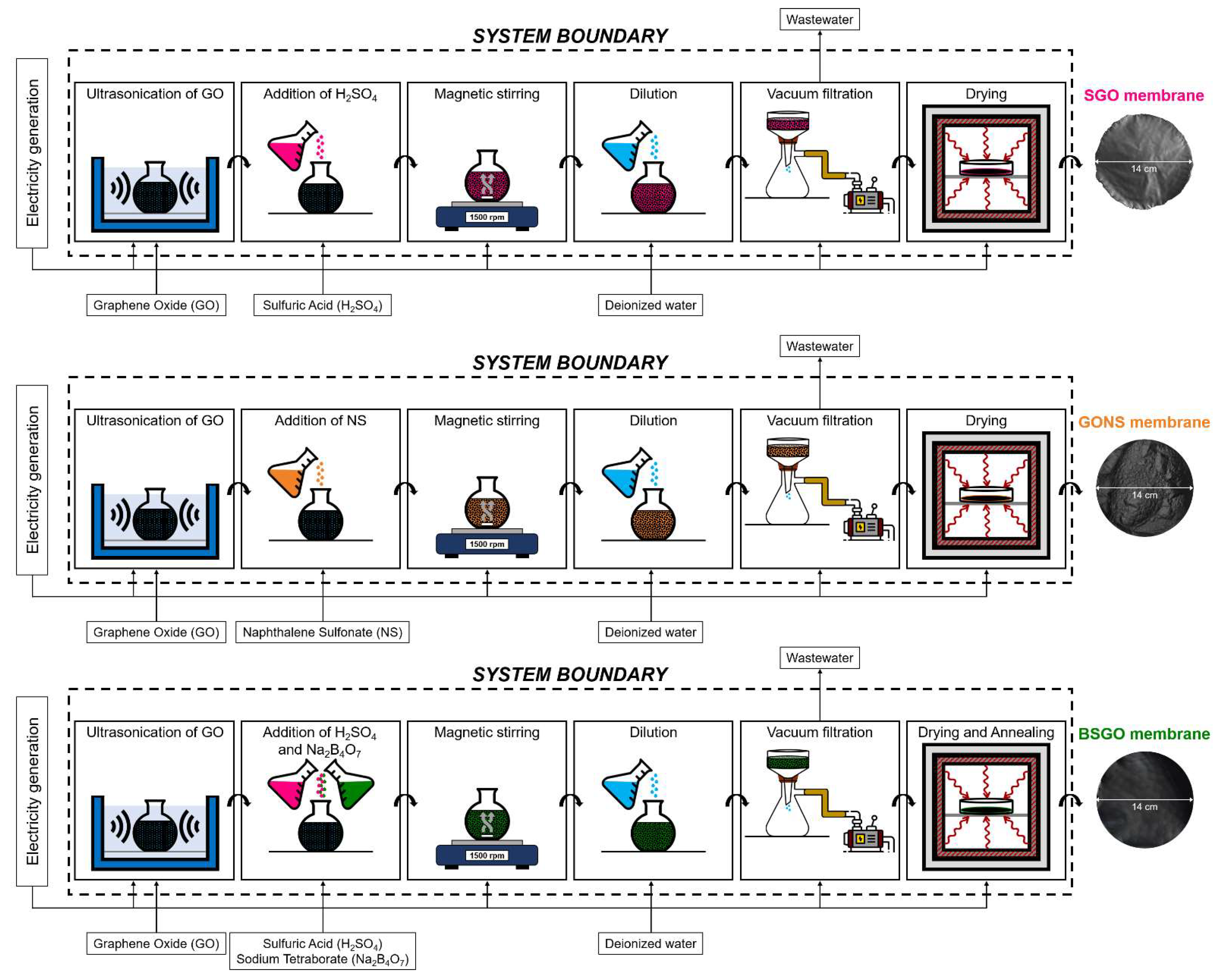
The laboratory fabrication procedures of sulfonated graphene oxide (SGO), graphene oxide-naphthalene sulfonate (GONS), and borate-reinforced sulfonated graphene oxide (BSGO) membranes are reported here below in detail.
Starting from SGO and GONS, controlled quantities of sulfonating agent (sulfuric acid for SGO, naphthalene sulfonate for GONS) were slowly poured into a round-bottomed flask containing 0.6 g of GO (150 mL of aqueous dispersion), which was preliminarily ultrasonicated by means of the LABSONIC LBS 1-H3 bath (Falc Instruments s.r.l., Treviglio, BG, Italy) for 15 min. In detail, an SGO sample was prepared with 15.9 g of concentrated H
2SO
4 (sulfuric acid-to-GO molar ratio of 10), while a GONS sample was fabricated with 0.783 g of NS (GO-to-NS molar ratio equal to 5) [
27,
28]. Next, the flask was connected to a reflux condenser, immersed into an oil bath, and placed on an RCT Basic IKAMAGTM safety control (IKA
®, Staufen im Breisgau, Germany) magnetic stirrer. The mixture was homogeneously blended at 1500 rpm for a total of 7 h under specific temperature control. Initially, the temperature was set up at 25 °C for 3 h, then it was increased to 100 °C with a transition time of 30 min; it was maintained for 3 h, and in the end, it was brought back to 25 °C in 30 min. Afterwards, the homogenized mixture was diluted with deionized water (600 mL for SGO and 300 mL for GONS, respectively) and vacuum-filtered through a circular polyvinylidene fluoride (PVDF) filter (Durapore
®, Merck Millipore, Burlington, MA, USA) on a Büchner funnel whose diameter was 14 cm (final membrane area of 153.94 cm
2). A vacuum pump model RV5 (Edwards, Burges Hill, UK) was employed for such purpose. Filtration time was 1.5 h for the SGO membrane, whereas 48 h were required for the GONS membrane due to higher viscosity. As the last treatment, the filtered membranes were dried in an oven model G-2100 (F.LLI GALLI G. & P. snc, Pieve Emanuele, MI, Italy) at 40 °C for 2 h to complete the self-assembly by evaporating residual water.
The preparation procedure of the borate-reinforced sulfonated graphene oxide (BSGO) sample was based on the one previously described for SGO, but it displayed some operational differences and additional steps. After the temperature-controlled magnetic stirring of the SGO slurry, 0.081 g of Na2B4O7·10H2O (corresponding to 2.125 mL of a freshly prepared 0.1 M aqueous Na2B4O7 solution) were trickled into the flask to attain a GO-to-borate molar ratio of 80. The mixture was further stirred for 15 min prior to vacuum filtration, which lasted for 2 h. The obtained membrane was oven-dried at 40 °C for 2 h, and then, as a final step, it was annealed at 90 °C for 1 h to promote the formation of borate bridges between GO layers.
2.3. Morphological Characterization
Attenuated total reflection Fourier-transform infrared (ATR-FTIR) spectroscopy experiments were carried out by means of the ThermoElectron Continuμm IR microscope coupled with a FTIR Nicolet Nexus spectrometer (Thermo Fisher Scientific, Waltham, MA, USA). The instrument worked through a single reflection silicon crystal and a mercury cadmium telluride (MCT) detector cooled by liquid nitrogen, recording spectra at a resolution of 4 cm−1, with 128 scans in an interval of wavenumbers of 650–4000 cm−1.
The EXSTAR 6000 TG/DTA 6300 (Seiko Instruments Inc., Tokyo, Japan) was used for thermogravimetric analyses (TGA) in an inert atmosphere guaranteed by a nitrogen (N2) stream of 55 mL min−1. A heating rate of 10 °C min−1 in the 25–1000 °C temperature interval was applied for all the experiments.
The scanning electron microscope (SEM) model EVO 50 EP (Carl Zeiss S.p.A., Oberkochen, Germany) was employed to inspect the cross-sections of the samples at 1000× magnification and to determine their thicknesses under conditions of 20 kV of accelerating voltage, 20 mA of current probe, and 10−5 Pa of chamber pressure.
2.4. Functional Characterization
Ion exchange capacity (IEC) of the three novel GO-based membranes and of Nafion
® 212, described as the milliequivalents of ionic sites able to exchange a proton per gram of dried material, was computed through Equation (1):
The parameters of Equation (1) were extrapolated from the IEC assessment through conventional acid–base back-titration, already presented by the authors in previous works [
27,
28]. For each membrane, the procedure consisted of four steps: (1) drying of the sample in the oven at 60 °C for 1 h aimed at measuring their dry mass (m
dry, g); (2) equilibration of the membrane portion in a 2 M aqueous NaCl solution for 48 h; (3) retrieval of the equilibrated sample; (4) back-titration of the post-equilibration solution against controlled volumes of an aqueous NaOH solution, whose concentration (C
NaOH) was 0.01 mmol mL
−1. The value of V
NaOH (mL) was identified as the one corresponding to the turning point in the obtained titration curves.
Electrochemical impedance spectroscopy (EIS) was employed for the investigation of the proton conductivity of the as-prepared samples, as well as of benchmark Nafion
® 212. The setup for EIS experiments [
27,
28] involved an inert Teflon
® holder supporting two stainless steel electrodes, a humid chamber endowed with an outer jacket for heated oil circulation, and a STEMlab™ 125–14 board (Red Pitaya, Solkan, Slovenia). The first step of the procedure was the clamping of previously dried rectangular samples (surface 3.5 cm
2) between the electrodes on the Teflon
® cell, which was then inserted in the humid chamber to expose them to specific conditions of temperature (in detail, 20, 60, and 80 °C controlled by means of a thermocouple) at 100% relative humidity (RH) for 1 h. By setting up a potentiostatic mode with a signal amplitude of 0.5 V in the frequency interval of 1–10
7 Hz, the sample response was examined via the Bode Analyzer of the STEMlab™ 125–14 board. The obtained Bode diagrams were converted into the corresponding Nyquist plots, which were fitted with the ZView
® software (Scribner Associates Inc, Southern Pines, NC, USA) by adopting an appropriate equivalent circuit. The authors opted for a modified Randles cell [
28], which is particularly suitable for the description of systems characterized by intrinsic non-ideality due to porosity and roughness of the electrode–electrolyte interface. Such circuit displays an ohmic resistance (R
s) in series with an RC element made up of the internal resistance (R
i) in parallel with a capacitive contribution known as the constant phase element (CPE). Considering the experimental values of internal resistance R
i (Ω) as the diameter of the Nyquist plots, the corresponding proton conductivity values (σ, S cm
−1) of the samples were extrapolated via the following Equation (2), where d (cm) is the distance separating the electrodes, w (cm) is the sample width, and t (cm) is the sample thickness:
The mechanical properties of the alternative membranes were evaluated by means of the Synergie 200 test system (MTS Systems Corporation, Eden Prairie, MN, USA). The tests were performed in tensile mode at a strain rate of 1 mm min−1 on 70 × 10 mm strips to build the corresponding stress–strain curves, according to which the tensile strength, strain at break, and Young’s modulus of each sample were extracted.
2.5. Life Cycle Assessment Methodology
The potential environmental performances of the three new membranes, i.e., SGO, GONS, and BSGO, were estimated by means of the LCA methodology as standardized by ISO 14040 (2006) [
41] and ISO 14044 (2006) [
42]. Details about the first two of the four LCA phases are disclosed in
Section 2.5.1 (Goal and Scope) and
Section 2.5.2 (Life Cycle Inventory), whereas the Impact Assessment and the Interpretation phases are discussed in
Section 3.3.
2.5.1. Goal and Scope
The goals of the LCA were (i) to uncover potential environmental hotspots in the production of the membranes and (ii) to juxtapose one of the main functional properties of the membranes (i.e., proton conductivity) with their environmental performance. The LCA was meant to provide a very preliminary environmental go or no-go for the novel materials. For comparative purposes, Nafion® 212 was included as benchmark.
The 16 impact categories recommended by the environmental footprint method EF3.0 were considered in the LCA [
43]. A single score evaluation in milli-ecopoints (mPt) of the environmental performance of the three membranes was also calculated with the set of normalization and weighing factors provided by the EF3.0 method. For the climate change category, the potential global warming impact using the characterization factors proposed in the latest IPCC (Intergovernmental Panel on Climate Change) assessment report (“AR6 Climate Change 2021: The Physical Science Basis”) was also estimated [
44]. As implemented in the SimaPro software, the IPCC 2021 impact assessment method considers a timeframe of 100 years, excludes CO
2 uptake and biogenic CO
2 emissions, and corrects the characterization factor for biogenic methane emissions to account for the previous CO
2 uptake.
For the hotspot analysis, the impacts referred to the production at lab-scale of one membrane with a surface area of 153.94 cm
2 (with different mass and thickness). This membrane size was the so-called declared unit (DU) for the cradle-to-gate assessment. This unit choice, however, does not enable any meaningful comparison among the different membranes. In fact, the role of the membranes in PEMFCs is to conduct protons in a reliable fashion at the operating conditions of the cell [
4,
45]. To compare the membranes in terms of this function would require extensive cell testing, which was not yet possible for the new membranes. Therefore, the comparison of the novel membranes and Nafion
® 212 was limited to a juxtaposition of the environmental performance per DU with the proton conductivity (σ), which was measured for all the membranes through the experimental setup described elsewhere [
28] at 80 °C and RH 100% (
Table S1, Supplementary Materials).
2.5.2. Life Cycle Inventory
The present study was based on evidence gathered at lab-scale. Therefore, the downstream boundary of the system was the exit gate of the laboratory (i.e., cradle-to-gate approach). The flows and the boundaries of the three designed procedures are sketched in
Figure 1. Primary data were used for the laboratory activities (i.e., amount of chemicals used in the syntheses and energy consumption of equipment). For the production of the chemicals, the supply of electricity and water, and for the wastewater treatment, the ecoinvent 3.8 database (cut-off system model) were used [
46]. The assessment was performed using the software SimaPro 9.3.0.3 [
47]. Laboratory equipment production was not included in the study, nor was any energy consumption related to laboratory services (e.g., lighting, heating, ventilation). Transport distances were accounted for by using “market for” datasets.
The inventory for the GO membrane production was based on Cossutta et al. [
48], which reported laboratory scale results on chemical graphite oxidation via different methods. The one chosen here was the modified Hummers method (Bangal variant). Consistently, the whole LCA of the three novel membranes relied on laboratory data.
3. Results and Discussion
3.1. Morphology
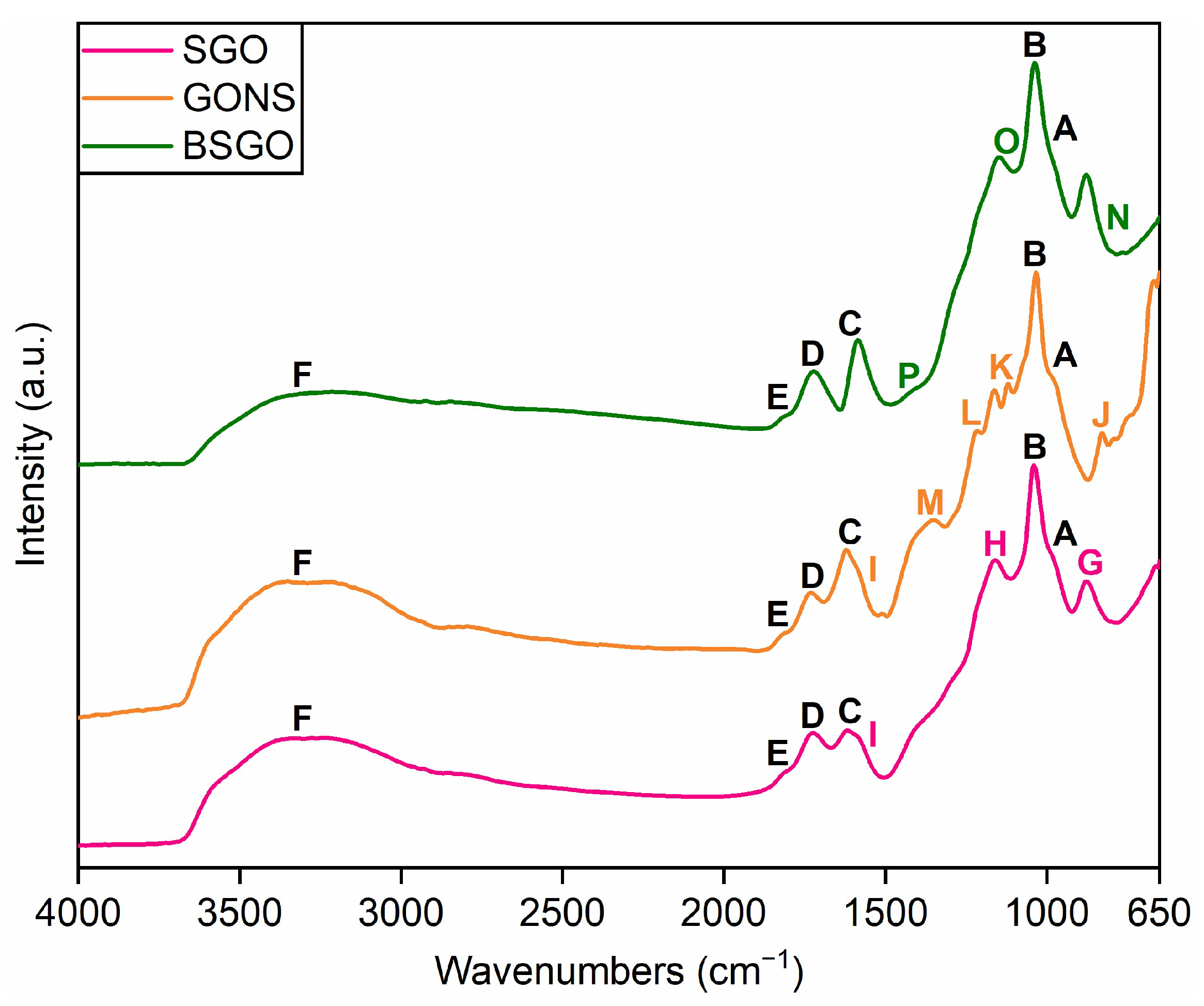
Figure 2 displays the ATR-FTIR spectra acquired for the investigated GO-based membranes. The GO-based structure involves some typical contributions that are common for all the membranes. The stretching of covalent bonds in unstable peroxides and lactols (C–O) and in tertiary alcohols (C–OH) could explain the contributions observed at (A) 981 cm
−1 and (B) 1035 cm
−1. The ones (C, D) at 1615 and 1728 cm
−1 could identify the bending of O–H bonds in adsorbed water molecules and the C=O stretching in carboxyl and carbonyl groups, respectively. The small contribution (E) at 1818 cm
−1 might match with C=O stretching in anhydride moieties. In the end, the ones related to the stretching of O–H bonds in tertiary alcohols, lateral carboxylic acid groups, and adsorbed water molecules superimpose to produce the broad structured band (F) detected between 2900 and 3700 cm
−1.
The successfulness of the different functionalization routes characterizing the studied membranes could be represented by some specific contributions. In the SGO spectrum, the band (G) recorded at roughly 880 cm−1 could be ascribed to the stretching of S–O in sulfonic (–SO3H) and sulfinic (–SO2H) acid groups. Moreover, the contribution (H) at about 1160 cm−1 may be attributed to the stretching vibration of the O=S=O bonds in sulfonic acid groups. The small shoulder (I) at approximately 1580 cm−1 may be compatible with the stretching vibration of C=C bonds in graphite-like sp2-hybridized domains, whose partial, though minimal, restoration could have been influenced by the slight removal of weak O-bearing moieties caused by the interaction with sulfuric acid.
In the GONS spectrum, the small contribution (J) identified at about 830 cm−1 might be related to the stretching of the S–OH covalent bond in –SO3H groups. The in-phase and out-of-phase vibrations of O=S=O in sulfonic acid groups could be represented by the contributions (K, L) at 1122 and 1219 cm−1, respectively. The one (M) centered at 1347 cm−1 could be assigned to the bending vibration of O–H bonds in phenol functionalities. Furthermore, the small contribution (I) at 1580 cm−1 is detected as well, but, in this case, it can be mainly attributed to the stretching of C=C bonds in the aromatic rings of naphthalene sulfonate molecules.
In the BSGO spectrum, both the small shoulder (N) found at 820 cm
−1 and the one (O) arising at about 1130 cm
−1 could be related to the symmetric stretching of the B–O bond in BO
4 structural units. Lastly, the asymmetric stretching of the B–O bond in BO
3 structural units could be recognized in the small contribution (P) identified at about 1430 cm
−1 [
50].
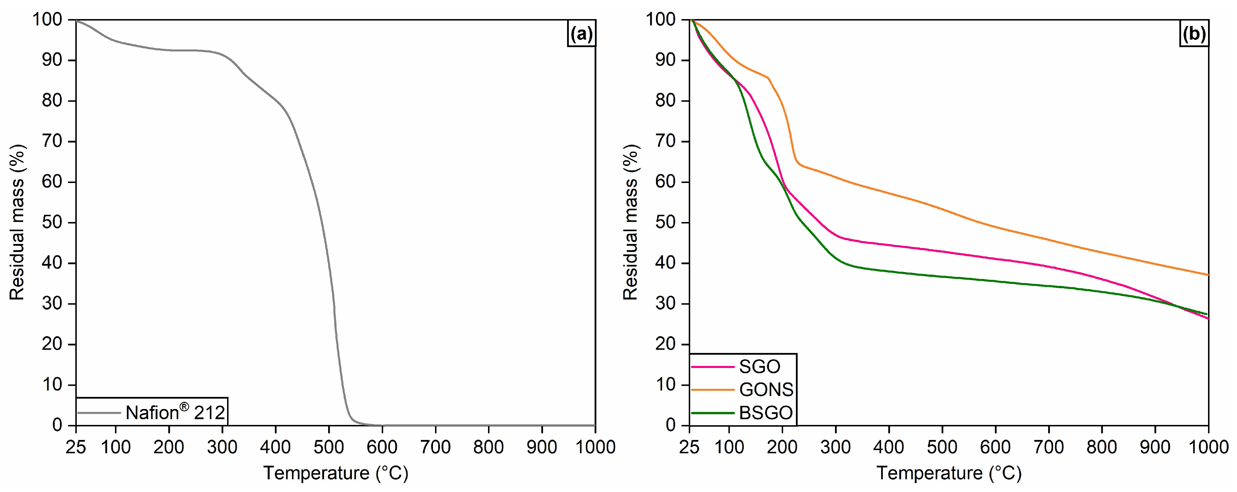
The thermograms of the GO-based membranes are collected in
Figure 3b, along with that of Nafion
® 212 (
Figure 3a). SGO displays four different ranges of mass loss. An initial 15% mass loss is observed in the neighborhood of 100 °C. It can be explained by the elimination of water molecules that are physically adsorbed on the GO framework by means of its hydrophilic moieties. The decomposition of less stable oxygen-containing functional groups (i.e., epoxides, carboxylic acids, tertiary alcohols), with consequent generation of CO
x by-products in gas phase, can account for the second mass loss of about 30% detected between 150 and 200 °C. Such loss is slightly more distinct than that of pristine GO discussed in a previous work from the authors’ research group [
27], and it occurs within a larger temperature range than the virgin material. This behavior could be explained by a combined removal of pre-existing oxygenated moieties in GO and unstable sulfonic acid groups, introduced with the sulfonation via sulfuric acid. The third loss of roughly 11% above 250 °C suggests the effectiveness of the proposed procedure, since it is specifically related to sulfur-containing functionalities and is absent in pure GO. Nevertheless, the narrower temperature range of such de-sulfonation with respect to the one observable in
Figure 3a for Nafion
® 212 (280–380 °C) may indicate a poor stability of the –SO
3H groups inserted on the carbonaceous sheets. The last loss, starting above 550 °C, is about 25% of the initial mass of the sample. It is associated with the continuous breakdown of the GO basal planes triggered at high temperature.
Concerning the thermogram of GONS, some slight differences can be observed. The first is the lower mass loss (≈12%) observed at about 100 °C. The sample appears to be more resistant to the evaporation of adsorbed water, indicating a possible higher tendency to retain humidity. Another difference is the smaller mass loss attributed to sulfur-bearing groups (≈3%), which may be symptomatic of a low quantity of functionalizing NS units in the GO matrix. The last difference is the greater overall thermal resistance of GONS, which displays the largest residual mass (≈40%) of all the investigated GO-based membranes. A positive influence of the naphthenic fractions exerted on the aromatic domains of GO can be hypothesized.
The crosslinked sample BSGO shows an overall trend similar to SGO. However, a larger loss of water above 100 °C can be observed due to the higher content of water molecules in the membrane caused by the introduction of sodium tetraborate decahydrate. Such mass loss overlaps with the one ascribed to labile oxygen functionalities between 150 and 180 °C. A further loss is then observed at around 200 °C, which could be identified as a combined loss of borate groups that failed to form a complete crosslinking and unstable sulfonic acid groups. The residual mass (≈27%) of BSGO is equivalent to that of SGO, excluding potential effects of crosslinking on the thermal resistance of the sulfonated membrane.
In general, the proposed GO-based membranes guarantee a higher thermal stability with respect to benchmark Nafion® 212, which completely decomposes below 550 °C. GONS appears to be the most thermally resistant among the synthesized materials. The retention of an adequate humidification level could be useful from the standpoint of proton conductivity.
Cross-sectional SEM images at 1000× magnification of the GO-based membranes are reported in
Figure 4, along with the average thicknesses derived accordingly. The stratification of multiple GO layers, promoted by the vacuum filtration step, is analogous for the different functionalization processes and leads to a similar compactness for the three membranes. Nevertheless, thickness values slightly vary due to the presence of different functionalizing species. The SGO membrane proves a thickness of 12.0 ± 0.9 μm, which is one order of magnitude higher than that of pristine GO (3.6 ± 0.2 μm) discussed in a previous study by the authors [
28]. Sulfonic acid groups grafted on the GO sheets can be identified as the main reason for such an increase in thickness. GONS is the thickest sample (17.1 ± 0.2 μm), coherently with the steric hindrance of the NS moieties whose intercalation causes a separation of adjacent GO sheets. On the contrary, BSGO is the thinnest membrane, with an average thickness of 11.6 ± 0.2 μm. A possible explanation is the effective crosslinking fostered by the formation of borate bridges (–B–O–C–) and the corresponding shrinkage of the distance between GO basal planes.
3.2. Functional Properties
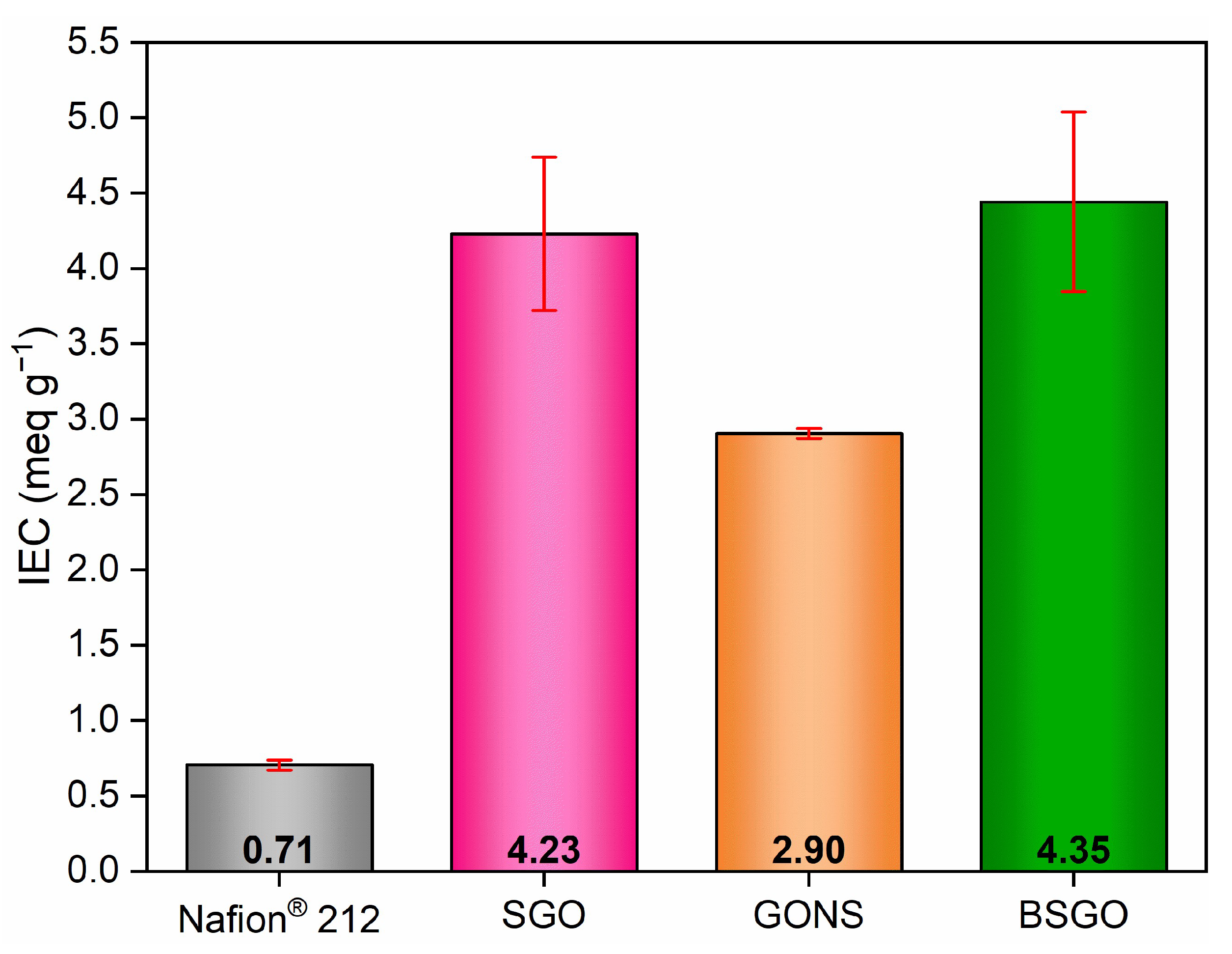
Figure 5 shows the average ion exchange capacity (IEC) outcomes of SGO, GONS, and BSGO compared to benchmark Nafion
® 212. All the GO-based membranes demonstrate a more pronounced tendency toward ion exchange than the commercial ionomer (IEC of 0.71 ± 0.03 meq g
−1), as well as toward that of the pure precursor (IEC of 0.76 ± 0.16 meq g
−1 [
27]). Moreover, the three samples overcome the IEC values of several other innovative proton exchange membranes discussed in the literature (generally about 1.5–2 meq g
−1) [
35,
36,
51,
52,
53,
54].
The IEC value of SGO is 4.23 ± 0.51 meq g−1. The functionalization by means of sulfuric acid guarantees a roughly six-fold improvement with respect to Nafion® 212 and GO. As a matter of fact, the strong propensity of SGO to exchange ions should be attributed to the introduction of a large amount of –SO3H groups. Therefore, a concrete modification of the GO framework seems to be confirmed.
GONS membrane provides an IEC of 2.90 ± 0.03 meq g−1. Despite a four-fold improvement with respect to Nafion® 212 and GO, which confirms a considerable ion exchange performance, the sample functionalized with naphthalene sulfonate has the lowest IEC among the investigated membranes. Such a result suggests a minor intercalation of NS moieties compared to the sulfonation via concentrated sulfuric acid. On the contrary, a better homogeneity of the GONS membrane can be inferred due to the consistency of results.
BSGO displays an IEC of 4.35 ± 0.65 meq g−1, which can be considered equivalent to the result provided by SGO. Borate functionalities appear not to alter the positive influence exerted by sulfonic acid groups on the GO framework, though the high variability could imply an undesired heterogeneous insertion of functional groups within the crosslinked membrane.
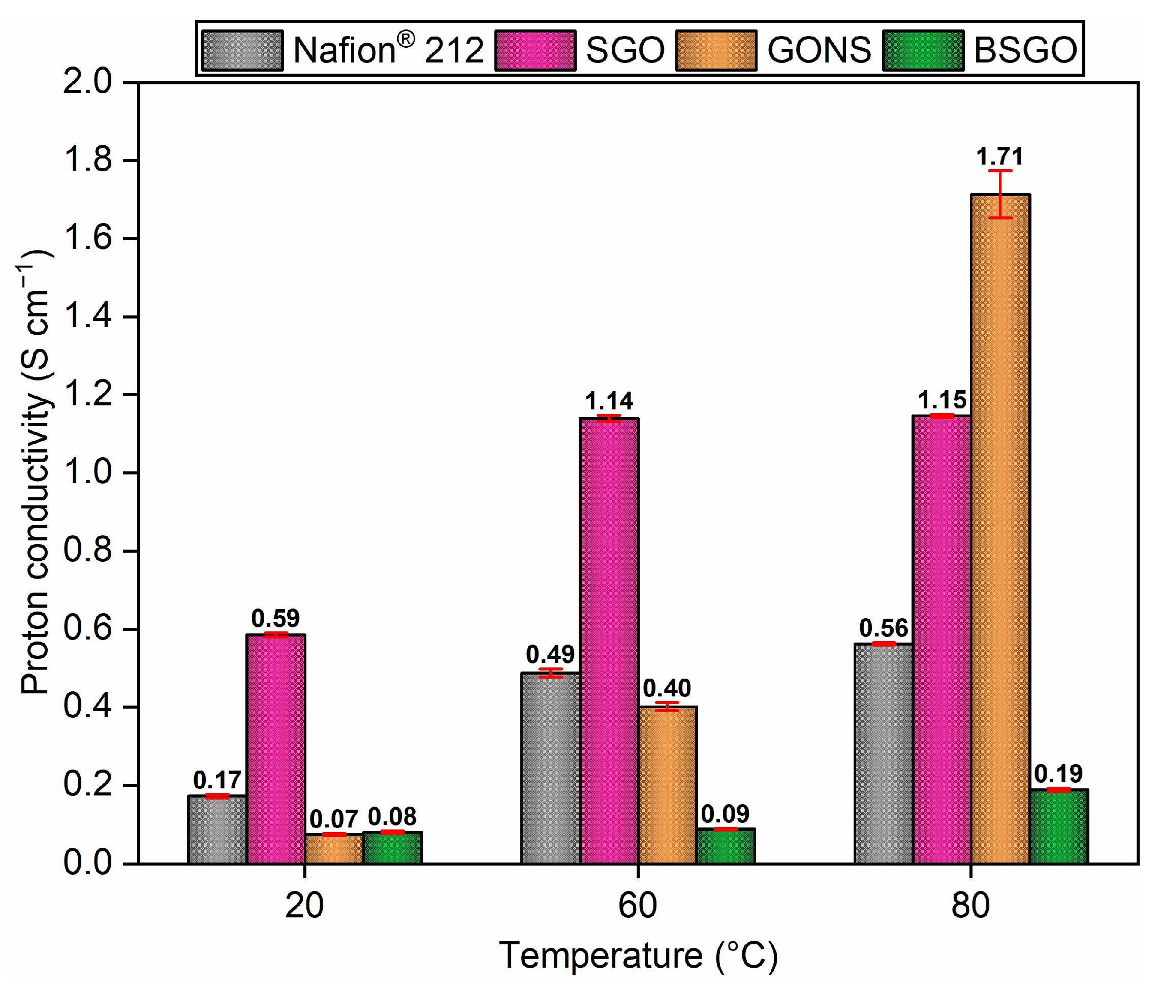
The proton conductivity results of Nafion
® 212, SGO, GONS, and BSGO, extrapolated from electrochemical impedance spectroscopy tests, are illustrated in
Figure 6. The increase in proton conductivity with temperature can be observed as a general trend for all the studied samples. As expected from what was discussed in other works [
35,
52,
55,
56], the mobility of protons within the membranes is favored at higher temperatures due to the easier passing of the corresponding energy barrier.
In SGO, the introduction of polar sulfonic acid groups on the GO carbonaceous skeleton positively influences the proton migration ability, in agreement with the already disclosed IEC results (
Figure 5). The outcomes range between 0.59 ± 0.01 S cm
−1 at 20 °C and 1.15 ± 0.01 S cm
−1 at 80 °C, exceeding the commercial electrolyte in every temperature condition. The advantage of –SO
3H groups is to accumulate water molecules through hydrogen bonding up to the formation of ionic clusters. In this way, an adequate membrane hydration can be obtained, and the relevance of the Grotthuss mechanism, according to which H
+ ions continuously hop through the water network, is improved. However, a slight overestimation of the average conductivity values, higher than those reported in the literature for innovative proton conductors [
35,
36,
51,
52,
53,
57], may have occurred due to unreacted sulfuric acid captured in the as-prepared membrane.
Even though the GONS membrane shows the lowest IEC performance, it guarantees the best proton conductivity performance at 80 °C (1.71 ± 0.06 S cm−1). This result, which is three times higher than that of Nafion® 212 at the same temperature (0.56 ± 0.01 S cm−1), could be attributed to the establishment of π-π interactions between the aromatic domains of GO basal planes and the benzene rings of the naphthalene sulfonate molecules. In this fashion, a direct pathway for proton transport is generated thanks to the microphase separation of well-hydrated regions and drier ones. The benefit of the functionalization via intercalation of NS molecules appears to be the preservation of a larger amount of water in the proximity of the sulfonic acid groups even at the highest investigated temperature.
The behavior of BSGO is exactly the opposite with respect to GONS, since the best IEC performance is not matched by adequate proton conductivity values, albeit the upward trend with increasing temperature is still visible. The outcomes range between 0.08 ± 0.01 S cm−1 (20 °C) and 0.19 ± 0.01 S cm−1 (80 °C), all worse than Nafion® 212. Borate bridges could presumably be constituted in a perpendicular direction with respect to parallel GO layers. Therefore, they could represent a physical barrier obstructing the migration of protons in the membrane by means of the Grotthuss mechanism. On the contrary, sulfonic acidic groups remain able to exchange ions, explaining the discrepancy between the IEC and proton conductivity results. In any case, the clear detrimental effect of crosslinking on the ability to transport protons must be addressed.
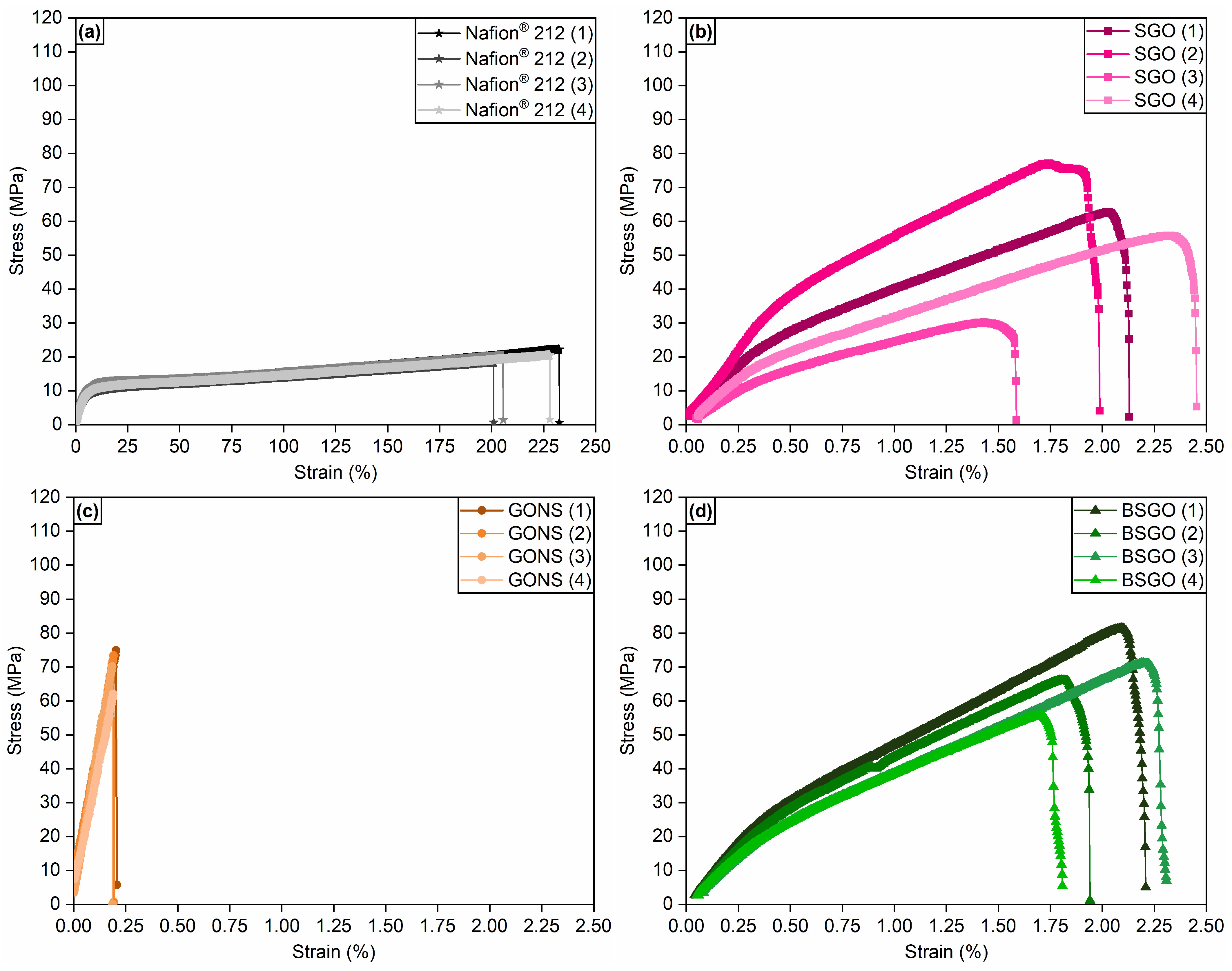
Figure 7 displays the stress–strain curves of Nafion
® 212 (a) and of the GO-based membranes (b–d). The mechanical performance of the analyzed samples is inferior with respect to Nafion
® 212, a behavior that was also reported for other proton-conducting materials [
51,
52]. The high maximum strain of the benchmark membrane, 216.74 ± 13.71%, indicates a remarkable plasticity, albeit achieved at relatively low tensile stresses (20.3 ± 1.3 MPa).
SGO (
Figure 7b) exhibits a quasi-linear trend due to the initial alignment of layers and their subsequent sliding up to total fracture. The corresponding maximum value of strain is 2.04 ± 0.31%, perfectly equivalent to the one of pristine GO (2.04 ± 0.51%). The main difference is the lower stresses needed in the former case to undergo failure, 56.5 ± 17.0 MPa, compared to 457.9 ± 120.9 MPa for the pure precursor [
28]. Two main factors can be considered to clarify such a dissimilarity. The first is the likely lower homogeneity of the sulfonated sample, already inferred from the IEC results. An inadequate distribution of sulfonic acid groups could lead to a more heterogeneous arrangement of GO sheets and a higher defect population. The second factor may be a slight deoxygenation provoked by the addition of sulfuric acid [
58], whose consequence is as well a worsening of defectiveness.
GONS (
Figure 7c) maximum elongation of 0.18 ± 0.04% permits its classification as a stiff and brittle material. The intercalation of NS functionalities amid GO layers causes a drop of one order of magnitude in both maximum strain and tensile strength (67.1 ± 7.7 MPa) with respect to the virgin material, albeit this last result is better than SGO. The steric hindrance of NS moieties could be supposed as the reason behind the clear loss in elongation ability, inasmuch the intercalated groups make adjacent GO layers more distant and complicate their reciprocal sliding. The consequence of such behavior would be an undesired difficult handling of the GONS membrane and its possible failure during the preparation of the membrane–electrode assembly (MEA), which would prevent an actual application of this material in a PEMFC.
BSGO mechanical behavior (
Figure 7d) evidences the obtainment of small benefits from the combination of borate and sulfonic acid groups with respect to SGO. As a matter of fact, tensile strength of the crosslinked material is the highest among the proposed GO-based membranes, with a value of 68.7 ± 9.3 MPa, whereas the maximum strain (2.07 ± 0.20%) is analogous to the results obtained for SGO and pristine GO. The establishment of borate bridges due to the completion of the crosslinking procedure appears to slightly reduce the rigidity of the material while continuing to allow the sliding of layers. However, the overall performance is still considered insufficient for practical use in PEMFC devices.
3.3. Life Cycle Impact Assessment and Interpretation
The environmental impacts per DU of the three membranes are presented in
Table 1. For the climate change category, results assessed with the EF3.0 and IPCC2021 are reported. Impact assessment results show far larger impacts for the novel membranes compared to Nafion
® 212 on a pure mass basis. However, the lack of a functional unit does not allow for a direct and consistent comparison. Additional normalized and single score results are presented in
Tables S3.1 and S3.2 of Supplementary Materials, respectively.
The contribution analysis of the GO-based membranes identifies electrical energy as the major source of impact (i.e., more than 99% of the potential climate change impact). This outcome might be attributed to the overconsumption of electricity in laboratory equipment with respect to energy-optimized industrial processes [
59,
60]. By reducing the overall energy consumption, a scale-up to pilot or industrial scale would likely drastically improve the environmental performances of the membranes [
61].
Consumption of electrical energy is also the reason why SGO and BSGO have extremely different environmental performances than GONS, whose fabrication in the laboratory requires about four times more electrical energy (mainly related to the very long vacuum filtration step: 48 h for GONS vs. 1.5 h for SGO and 2 h for BSGO).
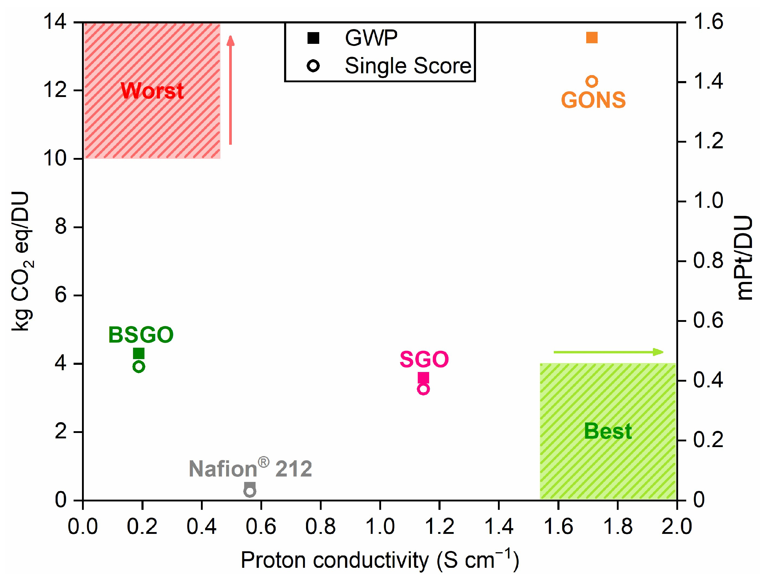
Since the primary function of a polymer electrolyte membrane is to conduct protons, the environmental performances are juxtaposed to the experimental proton conductivity values in
Figure 8. Specifically, the climate change impact (left
y-axis) and the single-score-weighted EF3.0 results (right
y-axis) are displayed. For clarity, an optimal membrane (i.e., with high proton conductivity and low carbon footprint) would lie on the bottom-right corner of
Figure 8. Except for ozone depletion, the conclusions would not change if any other impact category was used. The higher impact of Nafion
® on the ozone depletion category (
Figure S3.1) could be expected, because it is the only perfluorinated polymer among the ones compared, and ozone depletion is strongly affected by PFASs [
62].
The BSGO membrane displays a lower proton conductivity than the benchmark and also a higher environmental impact. On the other hand, SGO and GONS membranes show a better proton conductivity than Nafion
® 212, but higher environmental impacts. Among the three GO-based membranes, SGO appears to provide an acceptable trade-off between functional performance and environmental footprint. Nevertheless, it is important to notice that the environmental impact of the membrane is minimal compared to the overall impact of electricity produced via a fuel cell [
63]. A better proton conductivity could reduce hydrogen consumption during the use phase of the PEMFC, potentially offsetting the higher impact in the production phase of the membrane. More studies are therefore necessary to assess the actual environmental consequences of using the SGO and GONS membranes.
3.4. Sensitivity Analysis
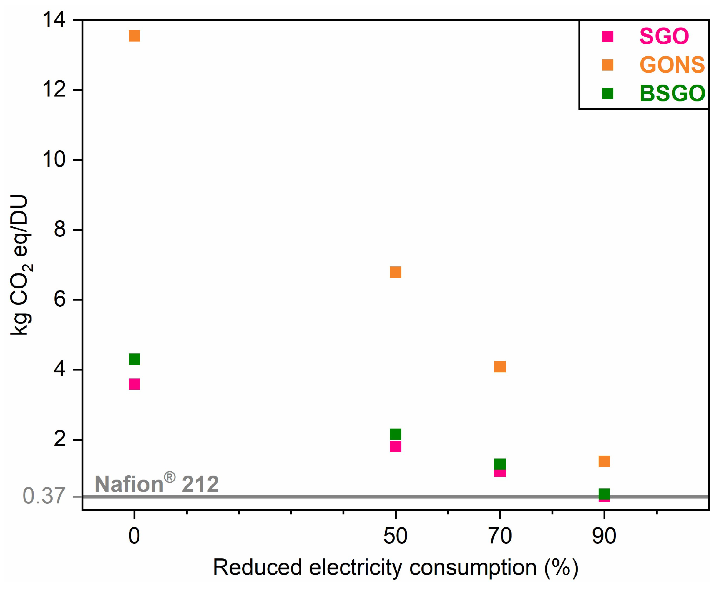
The impact assessment results revealed the primary role of the electrical energy consumed in the laboratory on the environmental impact of the novel membranes. However, the overestimation of electricity by using target data for laboratory equipment, together with non-optimized laboratory processes, makes the results not directly scalable to industrial processes. To partially overcome this problem, a sensitivity analysis was performed by varying the amount of electricity consumed in the laboratory fabrication procedures. In
Figure 9, the potential climate impacts with three levels of electrical energy reduction (i.e., 50%, 70%, and 90%) are reported. The environmental performance of the three novel materials becomes comparable with the benchmark (i.e., 0.369 kg CO
2 eq/DU) only when the electricity consumption is reduced by 90%. Specifically, the environmental impacts of the laboratory procedures for the fabrication of SGO and BSGO drop to 0.379 and 0.438 kg CO
2 eq/DU, respectively, whereas the one related to the GONS is equal to 1.373 kg CO
2 eq/DU. This last outcome confirms the preparation process of GONS as the one requiring the most urgent improvement in terms of energy usage, especially for what concerns the long vacuum filtration step. Optimizing energy consumption is therefore crucial for a scale-up to pilot or industrial level. According to a previous study on carbon-based materials [
64], an energy demand reduction in cradle-to-gate impacts comprised between 84% and 94% appears to be feasible. Such a reduction could be achieved by scaling up from small scale, corresponding to a technology readiness level (TRL) of 7–8, to large scale (TRL of 9–10). This kind of improvement could be assumed as potentially feasible for the studied GO-based membranes as well, by implementing a proper process optimization.
4. Conclusions
This study was devoted to exploring three novel GO-based materials as a potential alternative to the commercial electrolyte typically used in PEMFCs, i.e., Nafion®. Sulfonated graphene oxide (SGO), graphene oxide-naphthalene sulfonate (GONS), and borate-reinforced sulfonated graphene oxide (BSGO) self-standing membranes were fabricated according to three different laboratory procedures, which proved to be safe and reproducible.
Attenuated total reflection Fourier-transform infrared (ATR-FTIR) spectroscopy, thermogravimetric analyses (TGA), and cross-sectional scanning electron microscopy (SEM) highlighted an overall homogeneity of the samples, an adequate thermal stability, and a good combination between GO and the employed functionalizing materials.
The comparison with Nafion® was performed on two different levels. The first was related to the functional performances, which were investigated in terms of ion exchange capacity, proton conductivity, and tensile strength. IEC values of the GO-based membranes (4.23 meq g−1 for SGO, 2.90 meq g−1 for GONS, and 4.35 meq g−1 for BSGO) were significantly higher than that of commercial Nafion® 212 (0.71 meq g−1). Proton conductivity outcomes of SGO and GONS obtained at 80 °C were 1.15 and 1.71 S cm−1, respectively. These values were considerably higher than that of Nafion® 212 (0.56 S cm−1), indicating the potential suitability of SGO and GONS for an application in PEMFCs. However, their mechanical properties were worse than the commercial electrolyte.
The second level of comparison concerned the environmental impacts of the designed laboratory fabrication procedures, which were preliminarily assessed through LCA. BSGO was evaluated as a clear no-go, given its low proton conductivity and high environmental footprint. On the contrary, SGO appeared to be an acceptable trade-off between functional and environmental performances. Since LCA results were strongly affected by the energy consumption of the laboratory activities, a sensitivity analysis was performed. The outcomes underlined that only a sensible reduction in the energy usage (90%) could lower the impacts of the novel membranes to a level comparable to Nafion®.
The preliminary results of this work seem to suggest that the employment of PFAS-free membranes in PEMFCs is promising, but the reduction in the energy consumption related to the fabrication procedures is vital for the design of optimized pilot-scale or industrial production processes.
Future developments will aspire to improve the mechanical properties of the GO-based membranes and to test the best candidates in lab-scale devices, which would also permit the assessment of the actual environmental consequences of substituting the current PFAS-based membranes in PEMFCs.


 ,
, 


