
ElectroCatalytic Activity of Nickel Foam with Co, Mo, and Ni Phosphide Nanostructures


1
Department of Materials Science and Engineering, Faculty of Engineering, Imam Khomeini International University, Qazvin 34149, Iran
2
CIEFMA-Department of Materials Science and Engineering, Universitat Politècnica de Catalunya-BarcelonaTECH, 08019 Barcelona, Spain
3
Barcelona Research Center in Multiscale Science and Engineering, Politècnica de Catalunya-BarcelonaTech, 08019 Barcelona, Spain
*
Author to whom correspondence should be addressed.
Plasma 2022, 5(2), 221-232; https://doi.org/10.3390/plasma5020017
Submission received: 14 March 2022
/
Revised: 31 March 2022
/
Accepted: 25 April 2022
/
Published: 27 April 2022
(This article belongs to the Special Issue Feature Papers in Plasma Sciences)
Abstract
:In this study, the electrocatalytic activity of nickel foam, which is activated by cobalt, molybdenum, and nickel phosphide nanostructures, is prepared by the plasma hydrothermal method for use in the release of hydrogen and oxygen. The morphology and crystallographic structure of the synthesized phosphide specimens were examined by means of scanning electron microscopy, Fourier-transform infrared spectroscopy, and X-ray diffraction. Moreover, the electrolysis activity for these sets of specimens was investigated using the Tafel polarization curve or linear sweep voltammetry, cyclic voltammetry, as well as by means of the electrochemical impedance spectroscopy technique. Preliminary results show that nickel phosphide presents the highest electrocatalytic activity than the other phosphides developed in this research. In this regard, it presents an electrocatalytic activity to release hydrogen and oxygen of around −1.7 and 0.82 mV, which is measured at a current density of 100 mA·cm−2, respectively.
1. Introduction
Given the actual climate emergency and worldwide regulations that have been developed to reduce the carbon dioxide (CO2) and/or carbon monoxide (CO) emissions (also known as COx) and their financial penalties, the fuel economy and emissions reduction have become a key factor in most of the countries around the world. During the last decade, the use of clean energy, and in particular, hydrogen-based energy, has attracted the attention of many studies. Hydrogen is an ideal energy carrier that is widely employed in several industrial sectors (i.e., fuel cells, internal combustion engines, etc.) and it can replace fossil fuels.
The most widely used method for the production of hydrogen at an industrial length scale is through the conversion of fossil fuels to hydrogen. However, this method results in the release of COx and other polluting gases into the environment. On the one hand, this process promotes global warming, and therefore, climate change (i.e., it slightly increases the worldwide temperature, the acidity of the sea and ocean, etc.). On the other hand, the nature fossil fuel sources are decreasing considerably. On the basis of the aforementioned information, hydrogen production from water seems to be the most suitable methodology that is currently present in the market [1,2]. To date, the two main promising methods available for large-scale hydrogen and oxygen production are photoelectrochemical and electrochemical water fission track methods. The first method, which is suitable for hydrogen production, is an efficient, inexpensive, and environmentally friendly water oxidizing compound in artificial photosynthesis systems. Therefore, the electrocatalytic hydrogen release reaction is a highly efficient way to understand the transfer of electrical energy to chemical energy. This method is not only an important tool for understanding large-scale hydrogen production, but also for hydrogen production by water electrolysis and use in fuel cells [3,4,5].
It is well known that a hydrogen and oxygen release catalyst requires a large active surface area, high electrochemical stability, good conductivity, low hydrogen release overvoltage, good electrocatalytic activity, and high corrosion resistance. In this context, precious metals, such as platinum and palladium, with the advantage of low hydrogen release overvoltage, are extensively used as the main raw materials for the electrocatalytic process. However, due to their high cost and scarcity, they cannot be used on an industrial scale. Given the aforementioned information, cobalt, molybdenum, and nickel, as well as their base electrodes exhibit high electrocatalytic behavior for the release of hydrogen and oxygen. Moreover, these materials are the main candidates for industrial employment in these processes [6,7,8]. Phosphide, selenide, and sulfide intermediates have been widely used as electrocatalytic activities, which have been extensively investigated to understand the catalytic mechanism and the ability to enhance the catalytic activity by designing new electrodes [9,10,11,12].
The rapid emergence and development of nanotechnology-enabled humans has allowed for the fabrication of nanostructured materials for a uniform size and distribution of microstructures. For electrocatalysts, high specific levels in nanostructured materials can increase the hydrogen release activity [13]. On the one hand, plasma processing could be fast and environmentally friendly, depending on the plasma sources and processing, which leads to modifying the surface chemistry. Therefore, the catalytic properties at the superficial scale of materials enhance the catalytic activity of the resulting material [14]. On the other hand, the hydrothermal method leads to the production of nanostructures. This is an aqueous solution method that is placed at a high temperature and pressure, by dissolving a substance in one part of the system and transferring it to another part. Then, the substance was placed on a grain or crystal, which acts as a resonant reservoir. Given the aforementioned information, the aim of the present research is to provide an evaluation and comparison of the electrocatalytic behavior under service-like conditions of phosphide compounds (cobalt, molybdenum, and nickel), which are performed by hydrothermal and plasma methods.
2. Experimental Procedure
2.1. Materials
The following precursors were used to develop the cobalt, molybdenum, and nickel phosphide, denoted as CoP, MoP, and NiP: Cobalt chloride hexahydrate (CoCl2·6H2O), ammonium molybdate ((NH4) 6Mo7O24), nickel chloride hexahydrate (NiCl2·6H2O), hydrazine (N2H4) (all by Merck Chemical Reagent, Darmstadt, Germany). In addition, sodium hypophosphite (NaPO2H2) (by Fluka Chemical, Charlotte, NC, USA) was used. Distilled (deionized) water was used throughout the experiment, and 100 mL of polytetrafluoroethylene (PTFE) chamber was used for the synthesis process.
2.2. Hydrothermal Synthesis by Plasma
Various techniques are known for crystallizing materials from high-temperature aqueous solutions at high vapor pressures. The hydrothermal synthesis method can be used to synthesize single crystals in hot water or to separate hydrogen and oxygen from water, under certain pressures and temperatures. The process of crystal growth takes place in a device comprising a steel pressure tank known as an autoclave, in which a nutrient is supplied with water. A constant temperature gradient is imposed inside the crystal growth chamber. At the hotter end the nutrient solute dissolves, while at the cooler end it is deposited on a grain crystal, growing the desired crystal.
One of the hydrothermal methods is the formation of crystalline phases at a stable melting point and a plasma temperature point. Moreover, materials that have high pressure near their melting point can be cultured by the hydrothermal method. Therefore, in this project, this method has been used at the temperature of a plasma and special growth chamber to separate hydrogen and oxygen from nickel foam.
2.3. Sample Preparation
A piece of nickel (Ni) foam was sonicated in hydrochloric acid diluted (3 M HCl) with distilled water for 20 min, followed by 10 min sonication under acetone media. Then, it was washed with distilled water and dried under pure air. Through this process, the surface of the nickel foam was activated. To synthesize cobalt phosphide (CoP), the first 10 mL of 100 mM CoCl2·6H2O solution was dissolved in 10 mL of 100 mM NaPO2H2. Following this step, the addition of 2 mL of N2H4 hydrate and 78 mL of distilled water were included in the dissolution. Thereafter, the dissolution was homogenized with a stirrer for 15 min to obtain a clear aqueous solution, and then poured into a PTFE chamber. Next, the pre-treated Ni foam (20 × 10 mm) was added to the solution as a skeleton. The sealed chamber was placed in the oven at 180 °C for 5 h. A similar sintering process was conducted using the corresponding precursor to achieve the molybdenum and nickel phosphide (MoP and NiP, respectively). Following the synthesis process, a thin black layer of several hundreds of nanometers over the Ni foam of the corresponding phosphide was obtained. Finally, the obtained product was washed several times with water and ethanol, and subsequently dried for 12 h. At the end of the process, the obtained Ni foam and powder were placed in a tubular furnace with a controlled atmosphere of argon (Ar) at 300 °C for 1 h until the synthesized material transformed from an amorphous to crystalline structure. The heating and cooling rates during the sintering process were held constant at a temperature of 30 °C·min−1.
2.4. Characterization Techniques
2.4.1. Microstructural Characterization
For the microstructural characterization, the morphology of the synthesized samples was investigated using scanning electron microscopy (SEM, Hitachi S4160), with an energy-dispersive (EDS) detector (Oxford) to qualitatively quantify the chemical composition of each phosphide specimen (V = 20 kV, WD = 7). The composition of the synthesized phosphide samples was analyzed using Fourier-transform infrared spectroscopy (FTIR). FTIR spectra for the CoP, MoP, and NiP were collected using an FTIR spectrometer (Bio-Rad FTS 165). Following the sintering process, the crystallinity of the resulting materials was characterized using X-ray diffraction (XRD). XRD data for the CoP, MoP, and NiP were collected with a diffractometer (Philips X-pert Pro) using CuKα1 (up to 40 kV and 40 mA) radiation. The spectra were obtained in the ranges 15° ≤ 2° ≤ 60° at a scan rate of 0.02 s·step−1 and scan size of 0.02°.
2.4.2. Electrocatalytic Activity Characterization
The electrocatalytic activity, conducted by the Avium model (Vertex 20V1A), was carried out at 25 °C under a potassium hydroxide (KOH) aqueous environment using three different electrodes. Hg/HgCl and platinum were used as the reference and counter electrodes, respectively. In addition, the phosphine specimen was analyzed as the working electrode. In an alkaline medium, the sample remained in KOH solution for 30 min. Then, it was tested with a definite and constant surface. These samples were stabilized in an alkaline medium by linear sweep voltammetry (LSV) tests, Tafel polarization curves, cyclic voltammetry (CV), and electrochemical impedance spectroscopy (EIS), under an open circuit (OC) with a frequency ranging from 0.1 to 10 MHz. The potential amplitude was held constant at 10 mV. The results of the EIS electrochemical test were recorded as Nyquist, Bode, and phase diagrams.
3. Results and Discussion
3.1. Microstructural Characterization
The SEM morphology microstructure of the different phosphide electrodes is produced by the hydrothermal method (180 °C for 5 h), as shown in Figure 1. All of the residual microstructures present the resulting topography with high surface area, making these materials suitable for use as electrodes in the catalytic process for the production of hydrogen and/or oxygen.
As evident, each specimen presents different morphologies and shapes. In particular, the CoP (Figure 1a) presents a coral morphology structure, which is full of pores and vertical blades, making this electrode suitable for employment in catalytic applications. The MoP specimen (Figure 1b) presents a high porosity specimen, which comprises mainly of polygonal agglomerates. A more detailed observation of these agglomerates reveals that they comprise individual polygonal particles with a particle size of tens of nanometers (Figure 1b, right side). On the other hand, the NiP specimens present a monomodal particle size distribution with a spherical shape (Figure 1c). Moreover, the magnified micrograph highlights the fact that these particles are agglomerates that comprise nanoparticles of tens of nanometers (Figure 1c, right side). The resulting microstructure of different phosphides presents a network with high porosity. Here, the ions can easily penetrate and pass through the resulting structure, which provides the ability to oxidize and regenerate the resulting system during the electrolysis process.
The superficial chemical analysis, as well as the resulting spectra of the different samples investigated here, are presented in Figure 2. In addition, the chemical composition, in terms of percentage of metal ions and phosphorus that is present in the resulting structure, is summarized in Table 1. As can be seen in the chemical composition map (Figure 2b and Table 1), the P content linearly decreases when the metallic content increases.
The XRD patterns of the different samples synthesized here (180 °C for 5 h) are recorded in a wide range of Bragg angles of 2° (15° ≤ 2° ≤ 60°), as shown in Figure 3. The corresponding XRD patterns for CoP and NiP in Figure 3a,c are demonstrated in a fair agreement with those reported in [15,16,17]. However, the XRD spectra for MoP do not present a fully crystalline structure, as shown in Figure 3b. The FTIR spectra for the different phosphides synthesized here are presented in Figure 4, in which the phosphide bonds can be clearly seen in the diagram (denoted with a black dash line at 1078 and 1033 cm−1, in relation to the P–O bands). Furthermore, at 765 and 604 cm−1 (green dash line), these peaks correspond to the P–O bending vibration. These spectra are in fair agreement with those reported in [18,19]. The data reported by XRD and FTIR indicate the synthesis of phosphide structures: CoP (JCPDS No. 29–0497), MoP (JCPDS No. 75–0449), and NiP (JCPDS No. 65–0380).
3.2. Electrocatalytic Activity Characterization
The representation of the linear sweep voltammetry (LSV) at the cathodic and anodic states, as a function of the applied potential for the synthesized phosphide specimens conducted at a constant scanning rate of 25 mV·s−1, are presented in Figure 5a. In this graph, the LSV is represented for the Ni foam for comparison purposes with the produced phosphides. The CoP presents an additional potential of −1.81 V (gray dash line) at a current density of −100 mA·cm−2 (horizontal red dash line). On the other hand, at the same current density, the potential for MoP and NiP is presented at a similar value of around −1.71 and 1.70 V, respectively. In addition, the improved performance of the NiP specimen compared with the other specimens is related to its structure. This is mainly due to the fact that it presents a chemically active structure, which results from the spherical geometry (Figure 1c) and specific surface area that is lower than the other synthesized electrodes. Moreover, the oxygen release curve presented in Figure 5b exhibits the good behavior of NiP compared with the other specimens. Furthermore, the Tafel slope curve exhibits the high activity of different synthesized electrodes, as shown in Figure 5c.
In general, NiP has better performance in terms of oxygen release than MoP and CoP due to the differences in shape. This regular shape speeds up the synthesis of the phosphide sample to a considerably higher extent than the Tafel slope curve, which is different from MoP and CoP.
Figure 6 exhibits the cyclic voltammetry (CV) diagram for the different phosphide specimens. As can be seen, the MoP specimen presents the largest area, which indicates that it has the highest surface area. This observation is in fair agreement with the SEM micrographs presented in Figure 1b. Notably, three important factors influence the performance of electrode materials: Electrical and electrochemical activity, as well as the reversibility of reactions. This is evidenced by the CV pattern shown in Figure 6. Herein, the electrode materials that present these properties are considered as the most suitable materials for creating hydrogen-releasing reaction electrodes. Moreover, of note, the peaks of the cathodic and anodic reactions are presented in the CV diagram, which indicates the high activity of the different phosphides developed here.
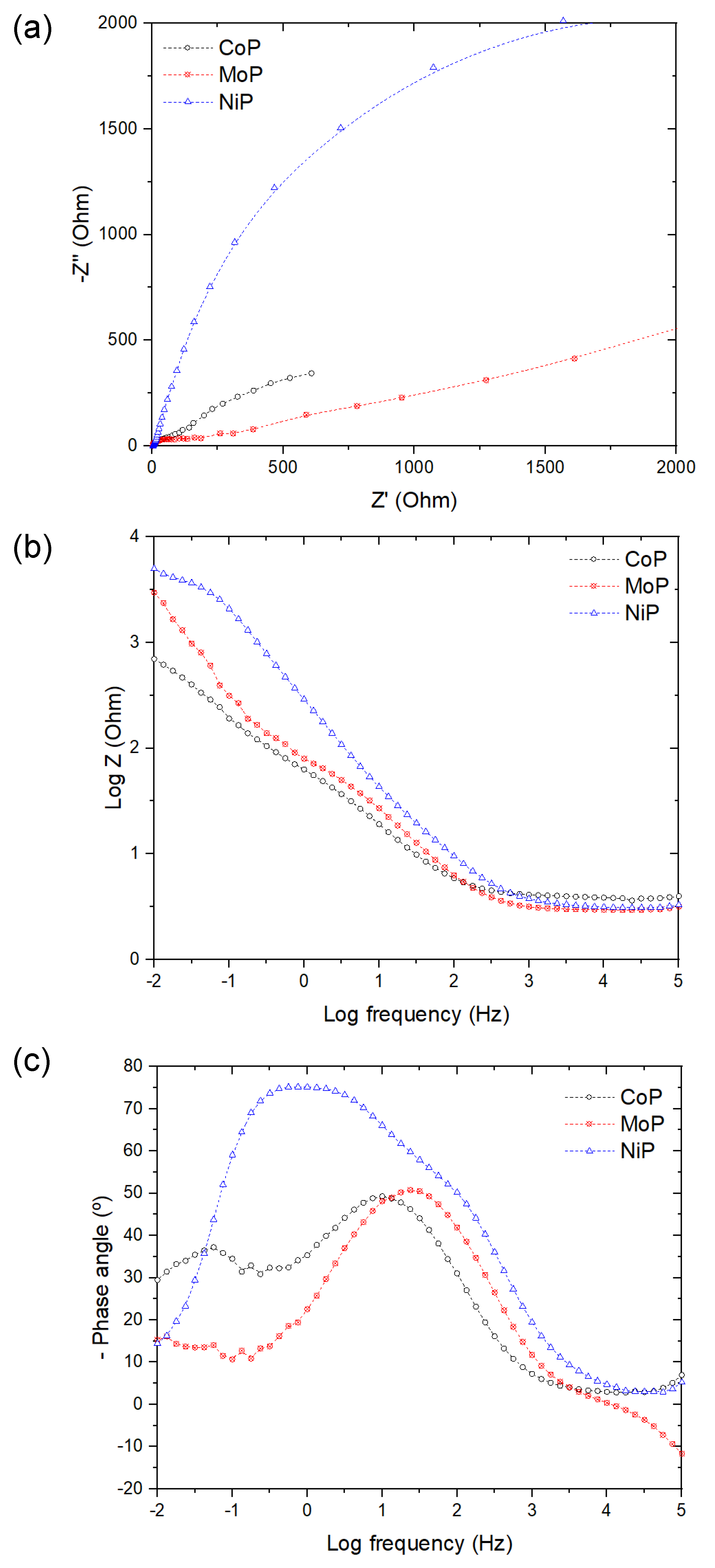
To investigate the mechanisms of the electrochemical activity for the synthesized phosphides, the electrodes are carried out through the electrochemical impedance test, as shown in Figure 7. The vertical and horizontal axes in Figure 7a exhibit the imaginary impedance (Z″) and the real impedance (Z′), respectively. The hydrogen release activity is higher, with the NiP specimen presenting the lowest ultimate strength and higher electrocatalytic activity, as shown by the LSV diagram in Figure 5. Moreover, from the EIS test, is it possible to represent the impedance as a function of the frequency of both axes in the logarithmic scale, which is known as the Bode diagram and presented in Figure 7b. From this representation, it is also possible to extract the resistance of the solution and the impedance at the lowest frequency, which is equal to the resistance of the whole system on the right- and left-hand sides of this diagram, respectively. Furthermore, from this experiment, is possible to achieve the phase diagram (Figure 7c), which correlates with the phase angle and impedance changes in terms of frequency.
As evident in the phase diagram (Figure 7c), the trend for CoP is slightly different from the two other phosphides investigated here. For the CoP specimen, it is possible to determine two different constants when two capacitors are present in the equivalent circuit. This highlights the failure of the electrolyte layer to penetrate into the substrate. The transfer of the phase angle at maximum frequency to higher values close to 90° indicates a less catalytic activity in hydrogen release [20]. Notably, in this diagram, the slope between the solution resistance and the final resistance is equivalent to the capacitive region. The increased capacitance indicates the barrier properties against the entry of electrolytes and corrosive agents into the coating and substrate.
4. Conclusions
In conclusion, the nanostructures synthesized from cobalt, molybdenum, and nickel phosphide were examined for infrastructure and catalytic activity in an alkaline and heat-treated environment (300 °C) and the desired results were obtained. The peaks of cobalt, molybdenum, and nickel phosphide were confirmed by XRD patterns and FTIR spectra. The SEM images of the structures show an irregular shape with high pore density. In addition, nickel phosphide has a spherical shape with high specific surface area. The electrochemical experiment results of the LSV, EIS, CV, and Tafel slope curves show the high electrocatalytic properties of nickel phosphide for the hydrogen decomposition process of water. Moreover, the higher volume of hydrogen, which is decomposed by this electrocatalyst, can be achieved at a given applied voltage. Furthermore, the use of a tube furnace for heating has prevented the material from oxidizing and some properties (i.e. morphology) have remained unchanged by the heat treatment, as evidenced by the SEM analysis.
Author Contributions
Conceptualization, M.S.Y.; formal analysis, J.J.R.R.; investigation, M.R.; writing—original draft preparation, M.R.; writing—review and editing, J.J.R.R.; project administration, M.S.Y. All authors have read and agreed to the published version of the manuscript.
Funding
This research received no external funding.
Institutional Review Board Statement
Not applicable.
Informed Consent Statement
Not applicable.
Data Availability Statement
Not applicable.
Conflicts of Interest
The authors declare no conflict of interest.
References
- Marini, S.; Salvi, P.; Nelli, P.; Pesenti, R.; Villa, M.; Kiros, Y. Stable and inexpensive electrodes for the hydrogen evolution reaction. Int. J. Hydrogen Energy 2013, 38, 11484–11495. [Google Scholar] [CrossRef]
- Nath, K.; Najafpour, M.M.; Voloshin, R.A.; Balaghi, S.E.; Tyystjärvi, E.; Timilsina, R.; Eaton-Rye, J.J.; Tomo, T.; Nam, H.G.; Nishihara, H.; et al. Photobiological hydrogen production and artificial photosynthesis for clean energy: From bio to nanotechnologies. Photosynth. Res. 2015, 126, 237–247. [Google Scholar] [CrossRef] [PubMed]
- Wilberforce, T.; El-Hassan, Z.; Khatib, F.N.; Al Makky, A.; Baroutaji, A.; Carton, J.G.; Olabi, A.G. Developments of electric cars and fuel cell hydrogen electric cars. Int. J. Hydrogen Energy 2017, 42, 25695–25734. [Google Scholar] [CrossRef] [Green Version]
- Emets, V.V.; Ponomarev, I.I.; Grinberg, V.A.; Mayorova, N.A.; Zharinova, M.Y.; Volkova, Y.A.; Nizhnikovskii, E.A.; Skupov, K.M.; Razorenov, D.Y.; Andreev, V.N.; et al. Development of hydrogen-air fuel cells with membranes based on sulfonated polyheteroarylenes. Russ. J. Electrochem. 2017, 53, 86–91. [Google Scholar] [CrossRef]
- González-Buch, C.; Herraiz-Cardona, I.; Ortega, E.; García-Antón, J.; Pérez-Herranz, V. Synthesis and characterization of macroporous Ni, Co and Ni–Co electrocatalytic deposits for hydrogen evolution reaction in alkaline media. Int. J. Hydrogen Energy 2013, 38, 10157–10169. [Google Scholar] [CrossRef]
- Sun, T.; Cao, J.; Dong, J.; Du, H.; Zhang, H.; Chen, J.; Xu, L. Ordered mesoporous NiCo alloys for highly efficient electrocatalytic hydrogen evolution reaction. Int. J. Hydrogen Energy 2017, 42, 6637–6645. [Google Scholar] [CrossRef]
- Kubisztal, J.; Budniok, A.; Lasia, A. Study of the hydrogen evolution reaction on nickel-based composite coatings containing molybdenum powder. Int. J. Hydrogen Energy 2007, 32, 1211–1218. [Google Scholar] [CrossRef]
- Subramanya, B.; Ullal, Y.; Shenoy, S.U.; Bhat, D.K.; Hegde, A.C. Novel Co–Ni–graphene composite electrodes for hydrogen production. RSC Adv. 2015, 5, 47398–47407. [Google Scholar] [CrossRef]
- Eftekhari, A. Electrocatalysts for hydrogen evolution reaction. Int. J. Hydrogen Energy 2017, 42, 11053–11077. [Google Scholar] [CrossRef]
- Xu, M.; Han, L.; Han, Y.; Yu, Y.; Zhai, J.; Dong, S. Porous CoP concave polyhedron electrocatalysts synthesized from metal–organic frameworks with enhanced electrochemical properties for hydrogen evolution. J. Mater. Chem. A 2015, 3, 21471–21477. [Google Scholar] [CrossRef]
- Pu, Z.; Saana Amiinu, I.; Wang, M.; Yang, Y.; Mu, S. Semimetallic MoP2: An active and stable hydrogen evolution electrocatalyst over the whole pH range. Nanoscale 2016, 8, 8500–8504. [Google Scholar] [CrossRef] [PubMed]
- Burchardt, T. The hydrogen evolution reaction on NiPx alloys. Int. J. Hydrogen Energy 2000, 25, 627–634. [Google Scholar] [CrossRef]
- Hong, S.H.; Ahn, S.H.; Choi, J.; Kim, J.Y.; Kim, H.Y.; Kim, H.-J.; Jang, J.H.; Kim, H.; Kim, S.-K. High-activity electrodeposited NiW catalysts for hydrogen evolution in alkaline water electrolysis. Appl. Surf. Sci. 2015, 349, 629–635. [Google Scholar] [CrossRef]
- Langmuir, I. The Interaction of Electron and Positive Ion Space Charges in Cathode Sheaths. Phys. Rev. 1929, 33, 954–989. [Google Scholar] [CrossRef]
- Li, M.; Liu, X.; Xiong, Y.; Bo, X.; Zhang, Y.; Han, C.; Guo, L. Facile synthesis of various highly dispersive CoP nanocrystal embedded carbon matrices as efficient electrocatalysts for the hydrogen evolution reaction. J. Mater. Chem. A 2015, 3, 4255–4265. [Google Scholar] [CrossRef]
- Xiao, P.; Sk, M.A.; Thia, L.; Ge, X.; Lim, R.J.; Wang, J.-Y.; Lim, K.H.; Wang, X. Molybdenum phosphide as an efficient electrocatalyst for the hydrogen evolution reaction. Energy Environ. Sci. 2014, 7, 2624–2629. [Google Scholar] [CrossRef] [Green Version]
- Pan, Y.; Chen, Y.; Lin, Y.; Cui, P.; Sun, K.; Liu, Y.; Liu, C. Cobalt nickel phosphide nanoparticles decorated carbon nanotubes as advanced hybrid catalysts for hydrogen evolution. J. Mater. Chem. A 2016, 4, 14675–14686. [Google Scholar] [CrossRef]
- Yao, Z.; Wang, G.; Shi, Y.; Zhao, Y.; Jiang, J.; Zhang, Y.; Wang, H. One-step synthesis of nickel and cobalt phosphide nanomaterials via decomposition of hexamethylenetetramine-containing precursors. Dalton Trans. 2015, 44, 14122–14129. [Google Scholar] [CrossRef] [PubMed]
- Nie, S.; Zhang, C.; Peng, C.; Wang, D.-y.; Ding, D.; He, Q. Study of the Synergistic Effect of Nanoporous Nickel Phosphates on Novel Intumescent Flame Retardant Polypropylene Composites. J. Spectrosc. 2015, 2015, 289–298. [Google Scholar] [CrossRef]
- Zhu, Y.; Zhang, D.; Gong, L.; Zhang, L.; Xia, Z. Catalytic Activity Origin and Design Principles of Graphitic Carbon Nitride Electrocatalysts for Hydrogen Evolution. Front. Mater. 2019, 6, 16. [Google Scholar] [CrossRef] [Green Version]
Figure 1.
SEM micrographs of (a) CoP, (b) MoP, and (c) NiP.

Figure 2.
(a) SEM micrographs; (b) chemical analysis maps (left-hand side) and EDS spectrum of CoP, MoP, and NiP.
Figure 2.
(a) SEM micrographs; (b) chemical analysis maps (left-hand side) and EDS spectrum of CoP, MoP, and NiP.

Figure 3.
XRD spectra of (a) CoP, (b) MoP, and (c) NiP.

Figure 4.
FTIR spectrum for each phosphide specimen prepared.

Figure 5.
LSV representation for CoP, MoP, and NiP. (a) HER representation, (b) Tafel slope, and (c) OER plot.
Figure 5.
LSV representation for CoP, MoP, and NiP. (a) HER representation, (b) Tafel slope, and (c) OER plot.

Figure 6.
CV representation for CoP, MoP, and NiP.

Figure 7.
EIS representation for CoP, MoP, and NiP. (a) Nyquist, (b) Bode, and (c) phase representations.
Figure 7.
EIS representation for CoP, MoP, and NiP. (a) Nyquist, (b) Bode, and (c) phase representations.


Table 1.
Summary of the chemical composition determined by the EDS analysis (in weight (wt. (%)) and atomic percentage (at. (%)), respectively) for the different phosphides investigated here.
Table 1.
Summary of the chemical composition determined by the EDS analysis (in weight (wt. (%)) and atomic percentage (at. (%)), respectively) for the different phosphides investigated here.
| Phosphide Specimens | CoP | MoP | NiP | |||
|---|---|---|---|---|---|---|
| Elements | Co | P | Mo | P | Ni | P |
| wt. (%) | 72.8 | 27.2 | 87.3 | 12.7 | 97.8 | 2.2 |
| at. (%) | 58.5 | 41.5 | 68.9 | 31.1 | 95.9 | 4.1 |
Publisher’s Note: MDPI stays neutral with regard to jurisdictional claims in published maps and institutional affiliations. |
© 2022 by the authors. Licensee MDPI, Basel, Switzerland. This article is an open access article distributed under the terms and conditions of the Creative Commons Attribution (CC BY) license (https://creativecommons.org/licenses/by/4.0/).
Share and Cite
MDPI and ACS Style
Saghafi Yazdi, M.; Rezayat, M.; Rovira, J.J.R. ElectroCatalytic Activity of Nickel Foam with Co, Mo, and Ni Phosphide Nanostructures. Plasma 2022, 5, 221-232. https://doi.org/10.3390/plasma5020017
AMA Style
Saghafi Yazdi M, Rezayat M, Rovira JJR. ElectroCatalytic Activity of Nickel Foam with Co, Mo, and Ni Phosphide Nanostructures. Plasma. 2022; 5(2):221-232. https://doi.org/10.3390/plasma5020017
Chicago/Turabian StyleSaghafi Yazdi, Morteza, Mohammad Rezayat, and Joan Josep Roa Rovira. 2022. "ElectroCatalytic Activity of Nickel Foam with Co, Mo, and Ni Phosphide Nanostructures" Plasma 5, no. 2: 221-232. https://doi.org/10.3390/plasma5020017