
Production of Permanent Magnets from Recycled NdFeB Powder with Powder Extrusion Moulding
 , ,
, ,  ,
,  and
and
Abstract
:1. Introduction

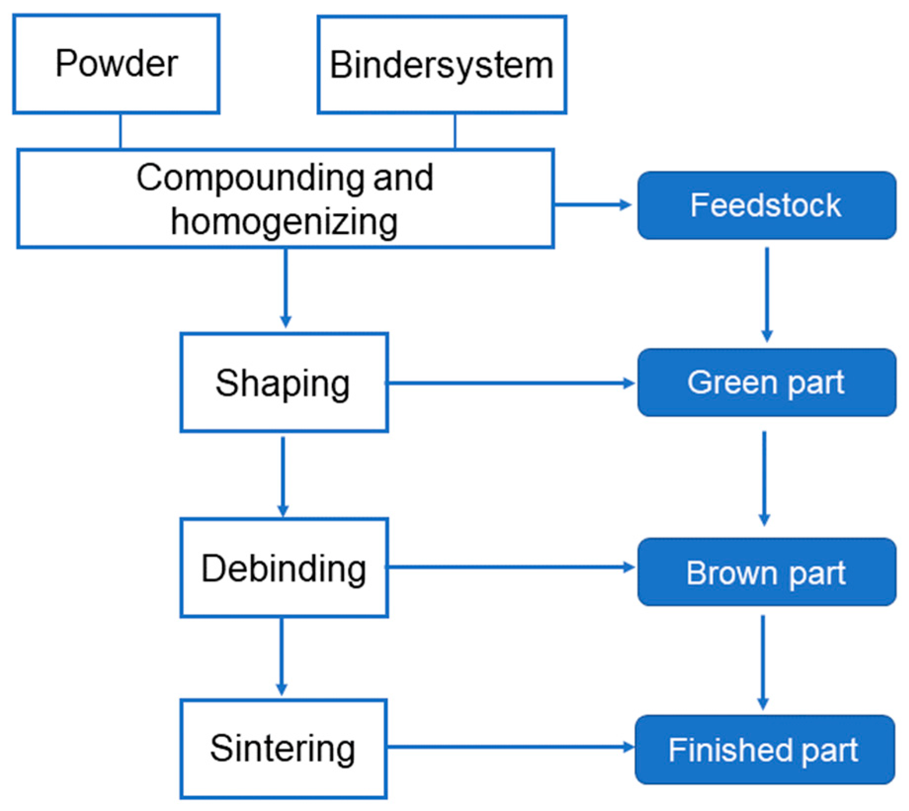
2. Experimental
2.1. Materials
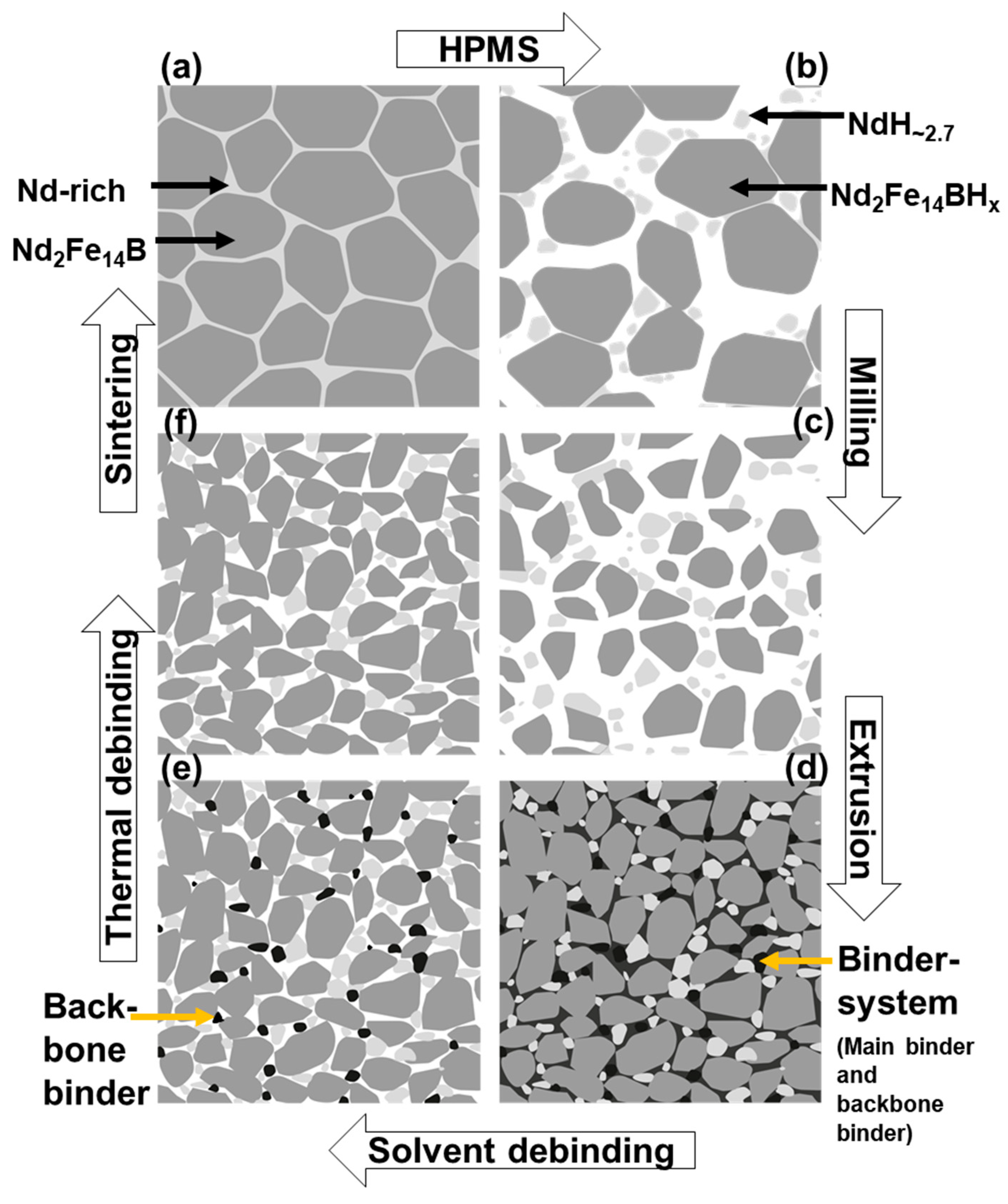
2.1.1. Powder Preparation
2.1.2. Binder System
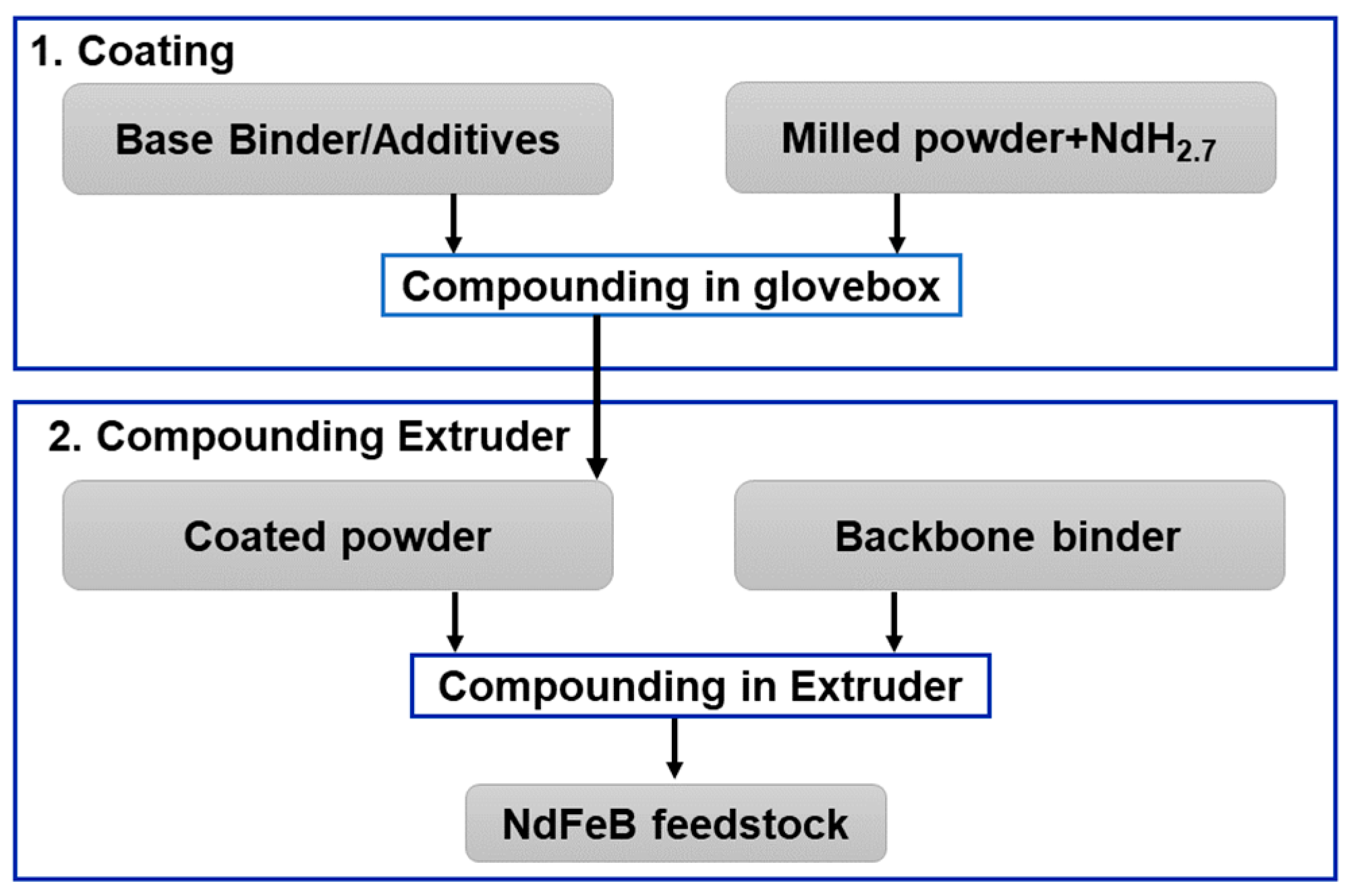
2.2. Compounding and Extrusion Process
- (a)
- Addition of NdH~2.7
- Feedstock A: 1 wt% NdH~2.7 addition;
- Feedstock B: 3 wt% NdH~2.7 addition;
- Feedstock C: 3 wt% NdH~2.7 addition, non-degassed powder.
- (b)
- Degassing of the powder HPMS powder
- (c)
- Powder loading
- (d)
- Screw speed
2.3. Debinding and Sintering
3. Results and Discussion
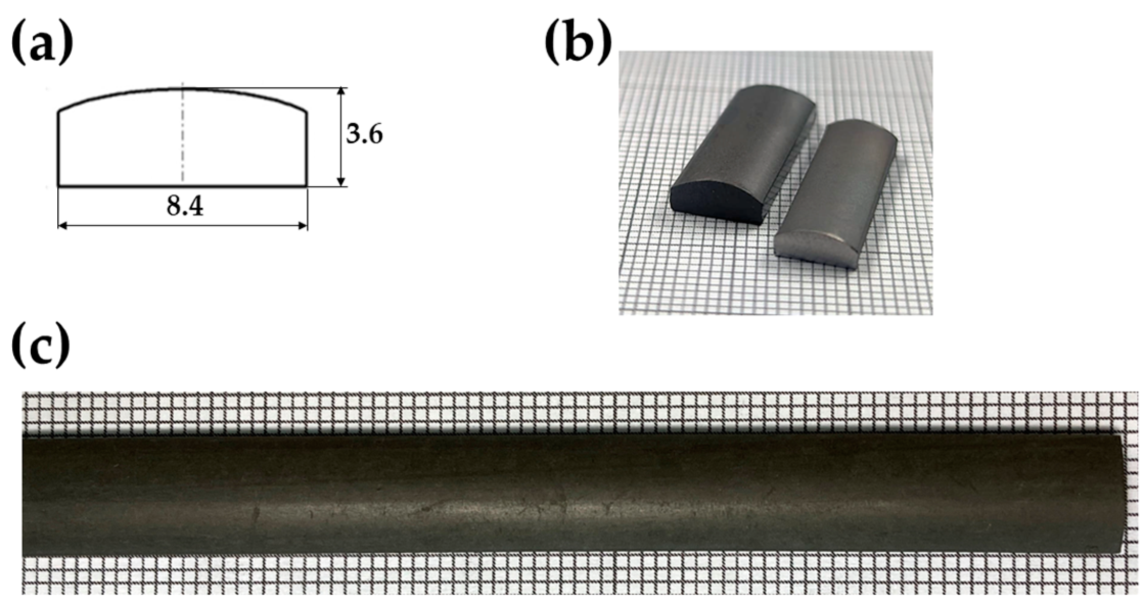
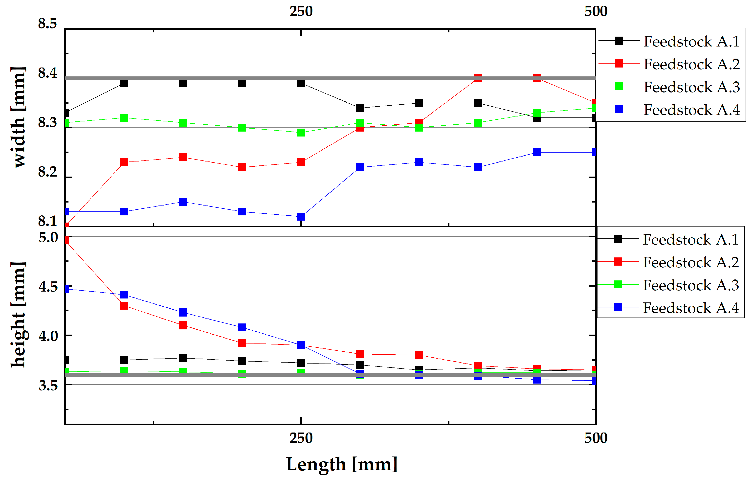
3.1. Dimension Stability of the Extruded Green Parts
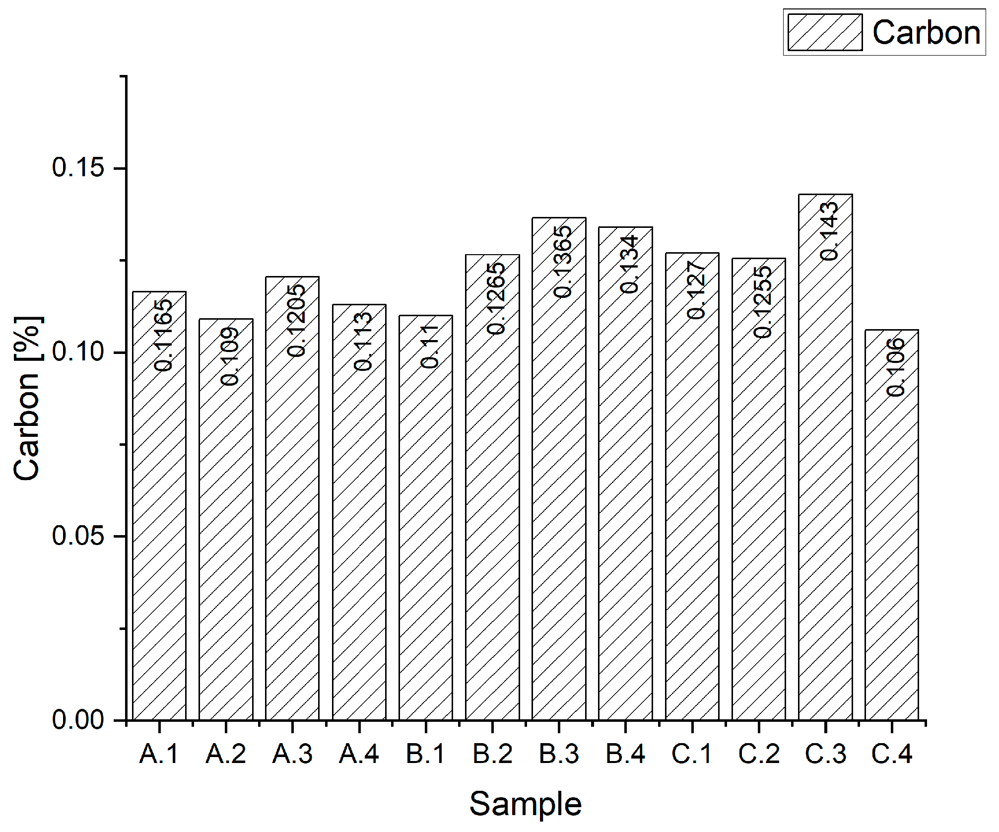
3.2. Carbon and Oxygen Content of Sintered Parts
3.3. Magnetic Characterisation of the Sintered Parts

| Sample | Hc (kA/m) | Br (mT) | Density [g/cm3] |
|---|---|---|---|
| A.1 | 1123 | 511 | 7.21 |
| A.2 | 1270 | 531 | 7.28 |
| A.3 | 956 | 555 | 7.20 |
| A.4 | 1053 | 539 | 7.21 |
| B.1 | 1429 | 531 | 7.23 |
| B.2 | 1353 | 547 | 7.23 |
| B.3 | 1137 | 534 | 7.15 |
| B.4 | - | - | 6.06 |
| C.1 | 1344 | 496 | 7.20 |
| C.2 | 1237 | 516 | 7.22 |
| C.3 | 1301 | 500 | 7.22 |
| C.4 | 1506 | 478 | 7.15 |
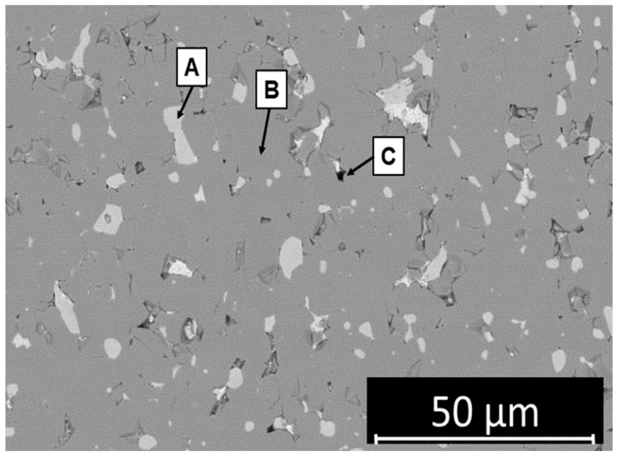
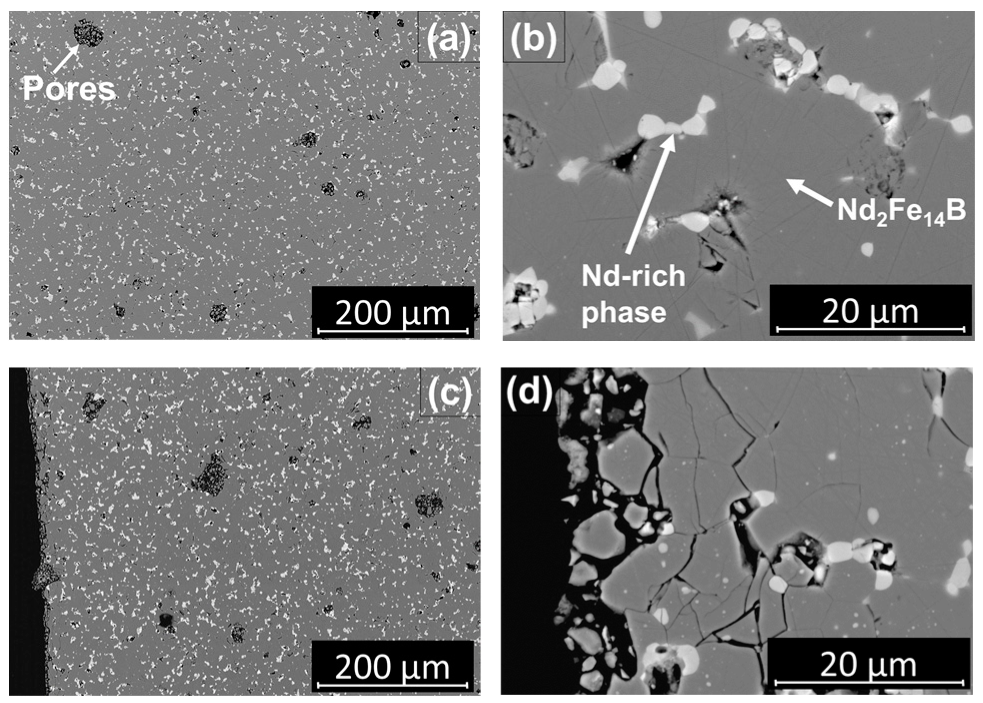
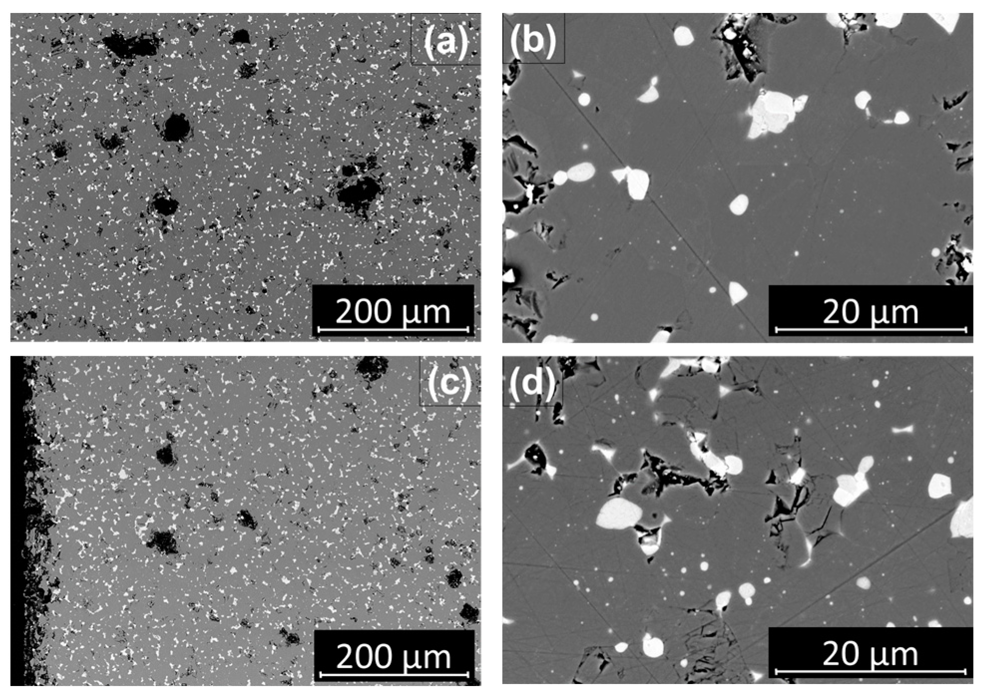
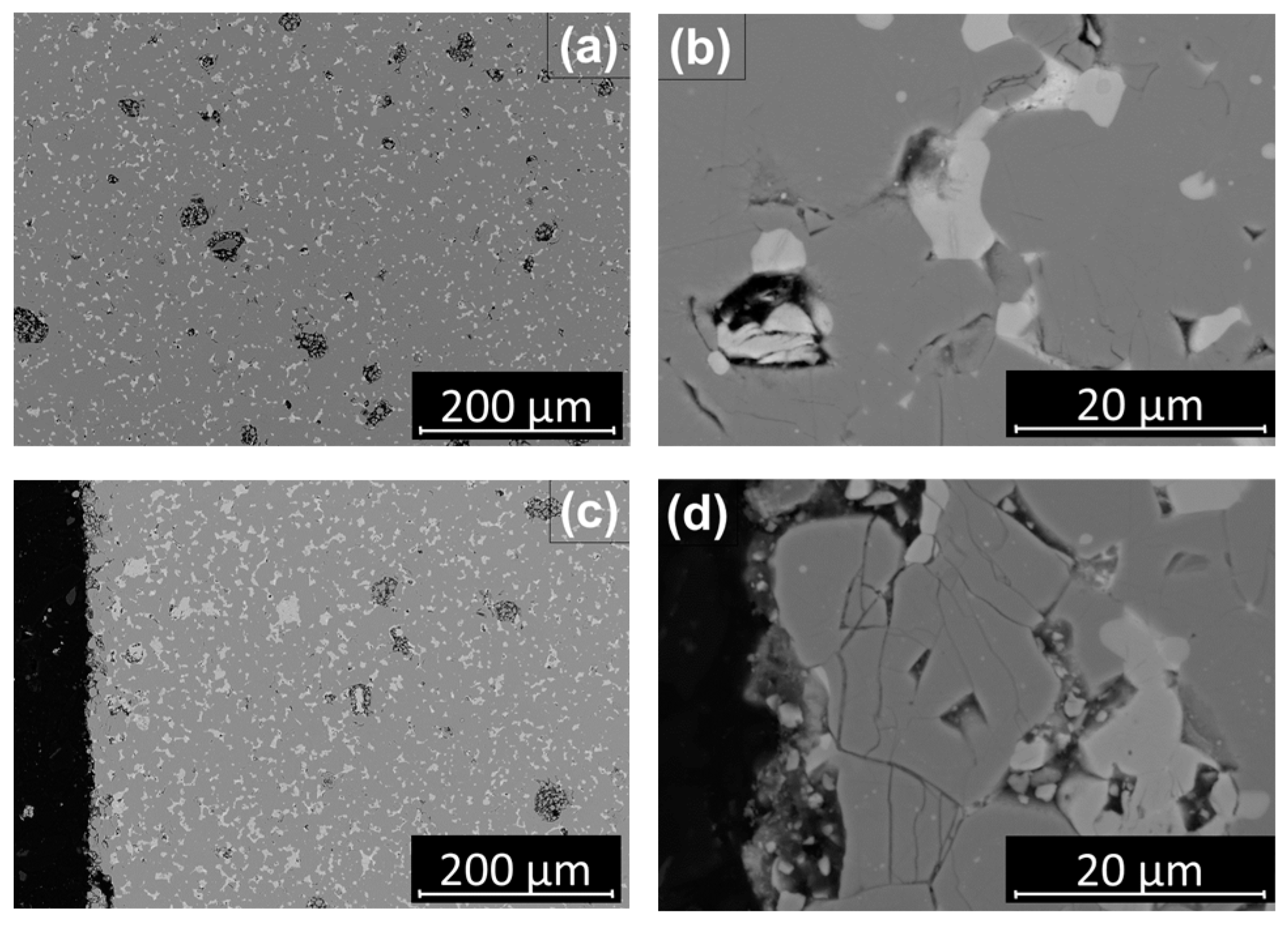
3.4. Microstructure of the Sintered Parts
4. Summary/Further Work
Author Contributions
Funding
Data Availability Statement
Acknowledgments
Conflicts of Interest
Appendix A. Microstructures of Sample A1–C3


References
- European Commission and Directorate-General for Communication. European Critical Raw Materials Act; Publications Office of the European Union: Luxembourg, 2023. [Google Scholar] [CrossRef]
- Gauß, R.; Burkhardt, C.; Carencotte, F.; Gasparon, M.; Gutfleisch, O.; Higgins, I.; Karajić, M.; Klossek, A.; Mäkinen, M.; Schäfer, B.; et al. Rare Earth Magnets and Motors: A European Call for Action; A Report by the Rare Earth Magnets and Motors Cluster of the European Raw Materials Alliance; European Raw Materials Alliance (ERMA): Berlin, Germany, 2021; Available online: https://erma.eu/european-call-for-action/ (accessed on 14 April 2024).
- Homepage Cordis European Commission, Horizon 2020. Sustainable Recovery, Reprocessing and Reuse of Rare-Earth Magnets in a Circular Economy (SUSMAGPRO). Grant agreement ID: 821114. Available online: https://cordis.europa.eu/project/id/821114 (accessed on 14 April 2024).
- Crozier-Bioud, T.; Momeni, V.; Gonzalez-Gutierrez, J.; Kukla, C.; Luca, S.; Rolere, S. Current challenges in NdFeB permanent magnets manufacturing by Powder Injection Molding (PIM): A review. Mater. Today Phys. 2023, 34, 101082. [Google Scholar] [CrossRef]
- Ma, B.; Herchenroeder, J.; Smith, B.; Suda, M.; Brown, D.; Chen, Z. Recent development in bonded NdFeB magnets. J. Magn. Magn. Mater. 2002, 239, 418–423. [Google Scholar] [CrossRef]
- Schatt, W.; Wieters, K.-P.; Kieback, B. (Eds.) Pulvermetallurgie. Technologien und Werkstoffe, 2., Bearb. Und Erw. Aufl. 2007; Springer: Berlin/Heidelberg, Germany, 2006. [Google Scholar]
- Rodewald, W.; Katter, M.; Reppe, G. Fortschritte bei pulvermetallurgisch hergestellten Neodym-Eisen-Bor Magneten. In Proceedings of the Hagener Symposium Pulvermetallurgie, Hagen, Germany, 28–29 September 2002. [Google Scholar]
- Sagawa, M.; Fujimura, S.; Togawa, N.; Yamamoto, H.; Matsuura, Y. New material for permanent magnets on a base of Nd and Fe (invited). J. Appl. Phys. 1984, 55, 2083–2087. [Google Scholar] [CrossRef]
- Hadjipanayis, G.C. (Ed.) Bonded Magnets. In Proceedings of the NATO Advanced Research Workshop on Science and Technology of Bonded Magnets, Newark, NJ, USA, 22–25 August 2002; Springer: Dordrecht, The Netherlands, 2003. [Google Scholar]
- Cheng, X.; Yu, X. Effect of Binder and Additives on Properties of NdFeB Bonded Magnets by Injection Moulding. J. Iron Steel Res. Int. 2006, 13, 282–285. [Google Scholar] [CrossRef]
- Beiss, P. Pulvermetallurgische Fertigungstechnik; Springer: Berlin/Heidelberg, Germany, 2013. [Google Scholar]
- Klocke, F. Fertigungsverfahren 5; Springer: Berlin/Heidelberg, Germany, 2018. [Google Scholar]
- Gonzalez-Gutierrez, J.; Stringari, G.; Emri, I. Powder Injection Molding of Metal and Ceramic Parts. In Some Critical Issues for Injection Molding, 1st ed.; Wang, J., Ed.; Article 3; INTECH: Houston, TX, USA, 2012; pp. 65–88. [Google Scholar] [CrossRef]
- European Powder Metallurgy Association (EPMA). Introduction to Metal Injection Moulding Technology. A Manufacturing Process for Precision Engineering Components, 4th ed.; European Powder Metallurgy Association (EPMA): Shrewsbury, UK, 2017. [Google Scholar]
- Kukla, C.; Imgrund, P.; Weber, O.; Schlauf, T.; Pickering, L.; Pischang, K.; Walton, A.; Gonzalez-Gutierrez, J.; Burkhardt, C. Metal Injection Moulding of NdFeB Based on Recycled Powders. In Proceedings of the World PM 2016 Congress and Exhibition, Hamburg, Germany, 9–13 October 2016. [Google Scholar]
- Lopes, L.U.; Hartwig, T.; Wendhausen, P.A.P. Evaluation of Process Variables in the Alignment Factor of Nd-Fe-B Magnets Made by Metal Injection Molding. IEEE Trans. Magn. 2013, 49, 4618–4621. [Google Scholar] [CrossRef]
- Hartwig, T.; Lopes, L.; Wendhausen, P.; Ünal, N. Metal Injection Molding (MIM) of NdFeB Magnets. EPJ Web Conf. 2014, 75, 4002. [Google Scholar] [CrossRef]
- Gonzalez-Gutierrez, J.; Thompson, Y.; Handl, D.; Cano, S.; Schuschnigg, S.; Felfer, P.; Kukla, C.; Holzer, C.; Burkhardt, C. Powder content in powder extrusion moulding of tool steel: Dimensional stability, shrinkage and hardness. Mater. Lett. 2021, 283, 128909. [Google Scholar] [CrossRef]
- Sotomayor, M.; Levenfeld, B.; Varez, A. Powder extrusion moulding of 430L stainless steel thin tubes for porous metal supported SOFCs. Powder Metall. 2011, 54, 103–107. [Google Scholar] [CrossRef]
- Banerjee, S.; Joens, C.H. Debinding and sintering of metal injection molding (MIM) components. In Handbook of Metal Injection Molding; Woodhead Publishing: Cambridge, UK; Philadelphia, PA, USA, 2012. [Google Scholar]
- Davies, B.; Mottram, R.; Harris, I. Recent developments in the sintering of NdFeB. Mater. Chem. Phys. 2002, 67, 272–281. [Google Scholar] [CrossRef]
- Burkhardt, C.; Weber, O.; Podmiljsak, B.; Gonzalez-Gutierrez, J.; Kukla, C.; Degri, M.; Harris, I.; Walton, A. Isotropic NdFeB hard magnets: MIM production using recycled powders with and without Nd additions. Powder Inject. Mould. Int. 2017, 11, 75–81. [Google Scholar]
- Lopes, L.U.; Santos, E.C.; Hartwig, T.; Wendhausen, P.A. Investigation of the influence of carbon on the magnetic properties of powder injection molded Nd-Fe-B magnet. In Proceedings of the 2015 IEEE International Magnetics Conference (INTERMAG), Beijing, China, 11–15 May 2015; p. 1. [Google Scholar]
- Minowa, T.; Shimao, M.; Honshima, M. Microstructure of Nd-rich phase in Nd-Fe-B magnet containing oxygen and carbon impurities. J. Magn. Magn. Mater. 1991, 97, 107–111. [Google Scholar] [CrossRef]
- Kim, A.S. Effect of oxygen on magnetic properties of Nd-Fe-B magnets. J. Appl. Phys. 1988, 64, 5571–5573. [Google Scholar] [CrossRef]
- Walton, A.; Yi, H.; Rowson, N.A.; Speight, J.D.; Mann, V.; Sheridan, R.S.; Bradshaw, A.; Harris, I.R.; Williams, A.J. The use of hydrogen to separate and recycle neodymium–iron–boron-type magnets from electronic waste. J. Clean. Prod. 2015, 104, 236–241. [Google Scholar] [CrossRef]
- Sprecher, B.; Kleijn, R.; Kramer, G.J. Recycling potential of neodymium: The case of computer hard disk drives. Environ. Sci. Technol. 2014, 48, 9506–9513. [Google Scholar] [CrossRef] [PubMed]
- Yang, Y.; Walton, A.; Sheridan, R.; Güth, K.; Gauß, R.; Gutfleisch, O.; Buchert, M.; Steenari, B.-M.; van Gerven, T.; Jones, P.T.; et al. REE Recovery from End-of-Life NdFeB Permanent Magnet Scrap: A Critical Review. J. Sustain. Metall. 2017, 3, 122–149. [Google Scholar] [CrossRef]
- Zakotnik, M.; Devlin, E.; Harris, I.R.; Williams, A. Hydrogen Decrepitation and Recycling of NdFeB-type Sintered Magnets. J. Iron Steel Res. Int. 2006, 13, 289–295. [Google Scholar] [CrossRef]
- Thomas, B.; Maelig, O.; Loïc, F.; Sorana, L.; Sébastien, R. Net-Shaped NdFeB Magnets Made By Powder Injection Molding: Lowering The Organic Contamination. In Proceedings of the World PM 2022 Congress and Exhibiton, Lyon, France, 9–13 October 2022. Session 68: Functional Materials Hard Magnetics. [Google Scholar]
- Tang, W.; Ouyang, G.; Cui, B.; Wang, J.; Dennis, K.W.; Kramer, M.J.; Anderson, I.E.; Cui, J. Magnetic and mechanical properties of grain-refined Dy-free Nd-Fe-B sintered magnets. J. Magn. Magn. Mater. 2021, 521, 167533. [Google Scholar] [CrossRef]
- Mottram, R.; Davis, B.; Yartys, V.; Harris, I. The use of metal hydride powder blending in the production of NdFeB-type magnets. Int. J. Hydrogen Energy 2001, 26, 441–448. [Google Scholar] [CrossRef]
- Bonten, C. Kunststofftechnik. In Einführung und GrundlagenMünchen; Carl Hanser Verlag GmbH & Co. KG: Munich, Germany, 2014. [Google Scholar]


| Fe | Nd | B | Dy | Pr | Cr | Ni | Si | Ce | Rare Earth |
|---|---|---|---|---|---|---|---|---|---|
| 64.78 | 27.60 | 0.99 | 4.17 | 0.10 | 0.01 | 0.01 | 0.20 | 0.0129 | 31.90 |
| HcJ [kA/m] | Br [mT] | Density [g/cm3] |
|---|---|---|
| 1400 | 1330 | 7.45 |
| Distribution | Powder Size |
|---|---|
| Dv(10) | 2.97 µm |
| Dv(50) | 7.68 µm |
| Dv(90) | 16.1 µm |
| Feedstock | Powder Loading [vol%] | NdH2.7 Add. [wt%] | Screw Speed [rpm] | Powder Degassed |
|---|---|---|---|---|
| A1 | 60 | 1 | 7 | Yes |
| A2 | 60 | 1 | 15 | Yes |
| A3 | 50 | 1 | 7 | Yes |
| A4 | 50 | 1 | 15 | Yes |
| B1 | 60 | 3 | 7 | Yes |
| B2 | 60 | 3 | 15 | Yes |
| B3 | 50 | 3 | 7 | Yes |
| B4 | 50 | 3 | 15 | Yes |
| C1 | 60 | 3 | 7 | No |
| C2 | 60 | 3 | 15 | No |
| C3 | 50 | 3 | 7 | No |
| C4 | 50 | 3 | 15 | No |
| Extrusion Parameters | Values |
|---|---|
| Temperature Zone 1 [°C] | 80 |
| Temperature Zone 2 [°C] | 150 |
| Temperature Zone 3 [°C] | 155 |
| Temperature Zone 4 [°C] | 155 |
| Temperature Zone 5 [°C] | 155 |
| Temperature Zone 6 [°C] | 160 |
| Screw speed fast [rpm] | 15 |
| Haul-off speed fast [m/min] | 0.2 |
| Screw speed slow [rpm] | 7 |
| Haul-off speed slow [m/min] | 0.1 |
Disclaimer/Publisher’s Note: The statements, opinions and data contained in all publications are solely those of the individual author(s) and contributor(s) and not of MDPI and/or the editor(s). MDPI and/or the editor(s) disclaim responsibility for any injury to people or property resulting from any ideas, methods, instructions or products referred to in the content. |
© 2024 by the authors. Licensee MDPI, Basel, Switzerland. This article is an open access article distributed under the terms and conditions of the Creative Commons Attribution (CC BY) license (https://creativecommons.org/licenses/by/4.0/).
Share and Cite
Rathfelder, S.; Schuschnigg, S.; Kukla, C.; Holzer, C.; Burkhardt, C. Production of Permanent Magnets from Recycled NdFeB Powder with Powder Extrusion Moulding. J. Manuf. Mater. Process. 2024, 8, 81. https://doi.org/10.3390/jmmp8020081
Rathfelder S, Schuschnigg S, Kukla C, Holzer C, Burkhardt C. Production of Permanent Magnets from Recycled NdFeB Powder with Powder Extrusion Moulding. Journal of Manufacturing and Materials Processing. 2024; 8(2):81. https://doi.org/10.3390/jmmp8020081
Chicago/Turabian StyleRathfelder, Stefan, Stephan Schuschnigg, Christian Kukla, Clemens Holzer, and Carlo Burkhardt. 2024. "Production of Permanent Magnets from Recycled NdFeB Powder with Powder Extrusion Moulding" Journal of Manufacturing and Materials Processing 8, no. 2: 81. https://doi.org/10.3390/jmmp8020081