Article

Enhancing Tool Performance in High-Speed End Milling of Ti-6Al-4V Alloy: The Role of AlCrN PVD Coatings and Resistance to Chipping Wear

1
McMaster Manufacturing Research Institute, McMaster University, Hamilton, ON L8S 4L8, Canada
2
Engineering Graduate Program-PPGEM, Pontificia Universidade Católica do Paraná, Curitiba 80215901, PR, Brazil
3
Kennametal GmbH, Altweiherstr 27-31, 91320 Ebermannstadt, Germany
4
HyLab-Green Hydrogen Collaborative Laboratory, 7520-089 Sines, Portugal
*
Authors to whom correspondence should be addressed.
These authors contributed equally to this work.
J. Manuf. Mater. Process. 2024, 8(2), 68; https://doi.org/10.3390/jmmp8020068
Submission received: 28 February 2024 / Revised: 15 March 2024 / Accepted: 22 March 2024 / Published: 29 March 2024

Abstract

:
The conventional cutting tools used for machining titanium alloys normally experience rapid tool wear, and it is generally difficult to achieve a cutting speed over 60 m/min. In this paper, a comprehensive study on improving the machining of Ti-6Al-4V alloy is presented, focusing on high-speed end milling at 100 m/min. Three different AlCrN PVD-coated cemented carbide tools were employed over cemented solid carbide endmills. The study aimed to understand the factors influencing tool performance and, particularly, the uncommon tool wear behavior characterized by chipping on the rake face. The research methodology involves a detailed investigation of coating properties, mechanical characteristics, surface defects, and tool edge geometries. Mechanical properties were measured to assess the resistance to plastic deformation and impact fatigue fracture resistance. Surface defects were meticulously observed, and tool edge geometries were evaluated through optical microscopies. These analyses uncover the key factors contributing to the best tool performance, notably the resistance to plastic deformation (H3/E2 ratio), impact fatigue fracture resistance, and maintaining uniform tool edge geometries. The results of this study reveal that the moderate stress C3 coating outperformed the other two coatings, exhibiting a 1.5-times-longer tool life, a relatively stable cutting force curve, and favorable friction conditions in the cutting zone.

1. Introduction

Titanium alloys, especially Ti-6Al-4V, have been widely used in various industries, such as aerospace and the biomechanical industry, due to their excellent mechanical properties and corrosion resistance [1,2]. However, Ti-6Al-4V is considered a hard-to-machine material, which limits its productivity, because of properties including low thermal conductivity, high hardness, a high chemical affinity for tool materials, and high work-hardening tendency [3]. As a result of the material’s inherent characteristics, when the cutting tools used for machining Ti-6Al-4V alloys are exposed to the high temperatures and cutting forces present in that environment, they are easily worn down.
Different types of cutting tool materials have been used over the years for milling Ti-6Al-4V in an attempt to improve tool life [4,5,6]. Priyabrata et al. studied the TiN- and AlTiN-coated tungsten carbide tools during micro-milling of Ti-6Al-4V. However, the cutting tools experienced high wear rates and friction coefficients because of the chemical affinity between the Ti and Al found in the tool material and the workpiece [7]. In another review paper, similar statements were included stating that, during Ti alloy machining, coated cermet tools that contained TiN and TiC showed chemical reactivity and adhesion between the tool and the workpiece material [8]. In addition, the ceramic tool and CBN tool were found to experience considerable groove wear on the flank and rake faces. The carbide tool and binderless CBN (BCBN), however, performed well when cutting titanium [9]. Coated cemented carbide tools have therefore been suggested for titanium machining to improve the tool life and surface integrity of the machined workpiece. However, the cutting speed of Ti-6Al-4V has been normally limited to 60 m/min in some studies because of the intense heat generated from accelerated speeds, which then results in complex wear mechanisms and plastic deformation in the cutting tools [10,11,12]. It has been found that some of the coatings have an active chemical reaction with Ti, which causes rapid tool wear [13]. Furthermore, adhesion and dissolution–diffusion were reported as the main types of wear that occurred on cemented carbide tools during titanium machining [14].
One important aspect that needs to be highlighted is the control of residual stress in physical vapor deposition (PVD) coatings, which has been a subject of extensive research due to its significant impact on the physical–mechanical characteristics of the substrate–coating system [15,16].
Residual stresses in PVD coatings are influenced by various factors, including the coating formation process and the parameters of the surface architecture [15]. These stresses, on the other hand, can affect the strength and wear resistance of the substrate–coating system. Recent studies have focused on understanding the physical nature and value of residual stresses in PVD coatings, revealing the characteristics of the coating formation process and the parameters of the surface architecture that influence these stresses, and also establishing the relationship between the strength and wear resistance of the substrate–coating system and the level of residual stresses [15].
Furthermore, multilayer coatings have been found to offer an advantage in controlling residual stress, which is often challenging to achieve with monolayer and bi-layer coatings [17]. Finite element modeling has been employed to verify the effect of the design of magnetron-sputtered multilayer Ti/AlN coatings on the distribution of residual stress [17]. However, it was also found that the multilayer AlCr/AlTi-based coating cannot prevent diffusion leading to a reduced tool life; instead, it may cause worse diffusion wear due to the interlayer defects compared to a AlCrN monolayer coating with a better adhesion strength to the substrate [18].
In addition to the control of residual stress in PVD coatings, it is also important to understand the effect of stoichiometry and the chemical composition of the coatings. For instance, Al-rich AlTiN and AlCrN coatings are known to have high hardness, high oxidation resistance, and favorable tribological characteristics under extreme machining conditions [19]. Controlling the Al content in the coatings inhibits phase transformation from the face-cubic center (fcc) to hexagonal close-packing (hcp), which offers better wear resistance and higher heat hardness [20]. AlTiN coatings possess higher thermal conductivity at an elevated temperature, while AlCrN coatings have excellent oxidation and abrasion resistance [21,22]. It was found that the hardness of coatings with Ti, Si, and Cr elements has a positive influence on the cutting tool life and cutting force when dry-milling Ti-6Al-4V [23]. Moreover, advanced arc PVD AlCrN coatings have been applied in the process of machining Ti-6Al-4V and have demonstrated enhanced frictional behavior and reduced cutting force [24].
However, there is still a lack of understanding regarding AlCrN coated tungsten carbide tools during the milling of Ti-6Al-4V, especially at cutting speeds over 60 m/min. The wear mechanisms that occur at higher cutting speeds could differ from those at lower cutting speeds, so it is worth identifying the unique wear mechanisms in order to optimize the machining process of Ti alloys and improve the cutting tool life. Thus, it is crucial to design an AlCrN PVD coating and understand the relationship between the mechanical properties and the wear performance of the coating. The goal of this paper is to investigate different PVD AlCrN-coated end milling tools in terms of their mechanical/physical properties and their influence on tool performance during the high-speed milling (at 100 m/min) of Ti-6Al-4V. In addition, detailed analyses of the AlCrN coatings will be discussed to determine the suitable cutting tools for specific applications, especially focusing on difficult-to-machine materials.

2. Experimental Procedure

AlCrN coatings were deposited on a tungsten carbide substrate using the cathodic arc method by industrial PVD equipment (Kennametal, Nabburg, Germany). Different deposition parameters are shown in Table 1. During the process, the nitrogen flow rate was controlled at a pressure of 4 × 10⁻² mbar. The temperature in the chamber was maintained at 480 °C. Three different AlCrN coatings with varying compressive stresses were deposited. The coatings were named as follows: C1, C2, and C3. C2 was a bi-layer coating, whereas C1 and C3 were monolayer coatings.
The coatings’ characteristics were assessed. A confocal white-light interferometry microscope (Infinite Focus G5, Alicona, Austria) was used to conduct nondestructive testing (NDT) for the surface topography of the coatings on coated coupons, as well as the cutting tool’s edge geometry. This system consisted of two modules: an EdgeMaster module was used for scanning, and a Laboratory module was used for geometric analysis. This microscope was also used for wear volume measurement of the cutting tool. The result illustrated in this work was the average value based on several measurements, with a 5% deviation. The AlCrN coating’s surface morphology was observed under both an optical microscope (VHX 5000, Keyence, Osaka, Japan) and a scanning electron microscope (JSM-6610LV, JEOL Ltd., Tokyo, Japan). To identify wear patterns on the cutting inserts, scanning electron microscopy (SEM) and energy dispersive spectroscopy (EDS) were used in conjunction. XRD measurement was conducted under the standard procedure using a Ti target (Kα avg 2.7497 Angstroms), with a power of 30 kV and 20 mA. The crystallographic plane of {222} was selected to measure the residual stress, with a Bragg angle (2θ) of 87°.
The mechanical properties of the AlCrN coatings were measured using a nano-indentation tester (NHT3, Anton Paar, Graz, Austria). The maximum load applied on the coatings was 50 mN, with a loading/unloading rate of 100 mN/min. A Berkovich Diamond indenter was used for this test, and the pause time for each indentation was 5 s. A scratch tester (Revetest, Anton Paar) was employed to evaluate the adhesion of the coating to the substrate following the ISO standard (19252:2008) [25]. A Rockwell Diamond indenter with a diameter of 100 μm was used. A linear progressive load of 0.5–70 N was applied, with a loading rate of 140 N/min and a speed of 6 mm/min. A total length of 3 mm was then created on the coating’s surface. A micro-impact fatigue test was conducted at room temperature on a nano test platform (Micro Materials Ltd., Wrexham, UK). The retracting height of the indenter was 12 μm, and one impact was produced every 4 s. The applied load was 20 mN, with a total test time of 300 s.
Cutting tools with the ISO catalog number HN440USA36021 (Kennametal, Germany) were used for end milling tests. The cutting tests in this study were conducted on a 5-axis, horizontal machining center (Makino-MC56, Makino, Tokyo, Japan). The milling parameters with the machine’s set-up are shown in Table 2. These parameters were selected to satisfy the high-speed milling operations with appropriate feed rates and depth of cut. A dynamometer (Kistler-9129AA, Kistler, Winterthur, Switzerland) was connected to the tool holder to monitor the cutting force during machining, and cutting force metrics were collected during each pass of the cutting test. The main purpose of the force measurements was to understand whether the adhesion of the workpiece material, which affects the cutting-edge geometry, and friction at the tool/chip contact area could significantly affect the RMS value of the forces. The sampling rate during the collection of the data was 2500 Hz to avoid aliasing issues of the signal. The overhang of the tool was 30 mm, and the frequency analysis of the data was obtained to check that there was no electrical noise, especially checking at 60 Hz and its harmonics. There was no filtering for these measurements, since nothing abnormal was found. Forces from three directions (feed Fx, thrust Fy, and axial Fz) were collected, and the feed force was selected to be analyzed. A LabView system (National Instruments, Austin, TX, USA) was used to analyze the forces by displaying a continuous-time waveform. The root mean square (RMS) mathematical method was used in this process and a root-mean-square deviation (RMSD) of 5% was applied, resulting in the average value of the data from the whole process.
The workpiece material in this study was a Ti-6Al-4V alloy, 220 mm long and 130 mm wide. The chemical composition and mechanical properties of this alloy are summarized in Table 3. The mechanical properties of the material were provided by the manufacturer and were the average values of at least three measurements.
The end of tool life (tool wear performance) criteria were based on ISO 8688-1:1989 [26], which establishes it as flank wear (VB) ≥ 300 µm or chipping ≥ 500 µm. An optical microscope (Keyence, Japan) was also used to measure tool wear and chipping along each pass. ANOVA analysis was conducted to acquire the wear data from an average of three tests for each variant, which led to an accuracy of 95%.

3. Results and Discussion

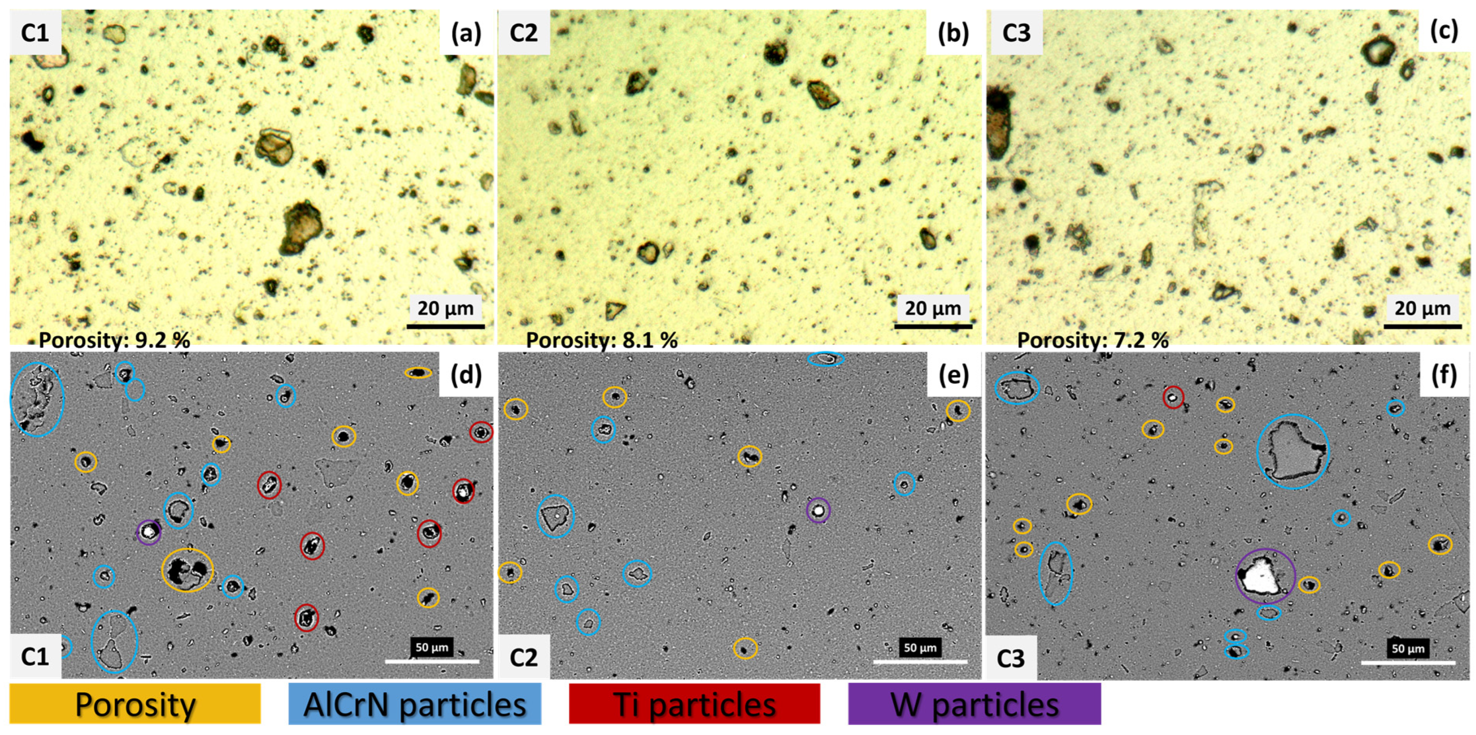
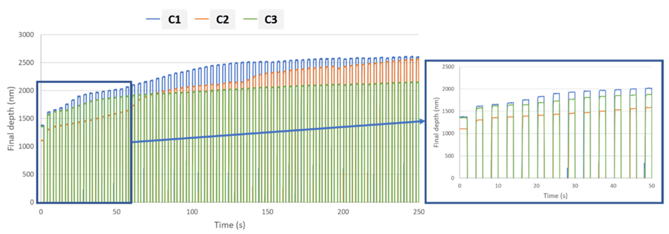
3.1. Characterization of AlCrN Coated Tools

Figure 1 shows the coating’s surface morphology under an optical microscope and SEM/EDS inspection. It can be seen from the upper optical images (Figure 1a–c) that all the coatings had droplet defects of various sizes and shapes occurring on the top layer. This type of defect is mostly found in arc PVD coatings [27,28], since arcs can cause the emission of micro-droplets that are incorporated into a coating during its growth. In addition, the area of the surface defects was measured as a function of the total area of the coating surface. The C1 coating had an average porosity of 9.2%, while the C2 and C3 coatings possessed values of 8.1% and 7.2%, respectively. The values were based on an average of three measurements in different regions of the coating, in which the difference in the defect ratio was a result of the deposition parameters (see Table 1) under which the AlCrN coatings were deposited, which affected the coating surface roughness, thermal stresses, and tribological characteristics. Furthermore, the presence of populous porosity on the coatings was observed from the SEM images (Figure 1d–f), which also depict the different element compositions identified by EDS. The C1 coating had relatively even AlCrN particles, but more Ti particles also appeared, which may have originated from the contaminated deposition. The appearance of the defects and porosities may have had an influence on the coating’s mechanical properties, such as hardness and adhesion to the substrate, which previous researchers have also observed [29]. The C3 coating contained dense morphology and a uniform structure with fewer pores and inclusions. This is favorable, since coating purity is needed to obtain better mechanical properties [30,31].
Figure 2 shows the SEM and EDS analysis of the AlCrN coating cross-section. It can be seen that the thickness of the coating in this study was around 3 μm. The coating exhibited a columnar structure, which was caused by the grain’s growth to its favorable orientations resulting in a crystallographic texture during the nucleation in the PVD process [32]. The principle of this phenomenon is also illustrated in [33]. As shown in Figure 1 and Figure 2, there were droplet and flake defects on the coating top surface, which is a normal result of the arc PVD process [33]. The EDS map shows the coating chemical composition is Al65Cr35N, and the substrate is WC.
The micromechanical properties and surface roughness of the three AlCrN PVD coatings are shown in Table 4. All three coatings possessed even surfaces, with low surface average values. Among them, the C3 coating had the lowest value, while the C1 coating had the most surface roughness. This was caused by the variation in coating deposition parameters (time and bias), which led to different distributions of surface defects (as shown in Figure 1). The C1 coating had a slightly higher hardness and elastic modulus, while the C3 coating exhibited the lowest values. This correlated to the coating deposition parameters, such as bias voltage and arc current. Generally, the higher the negative bias voltage was, the more kinetic energy ions the coating possessed and, thus, the more defects were created [34]. The defects typically led to a hardness increase. However, it is also possible that the higher bias voltage escalated the temperature of the substrate, resulting in the coatings recrystallizing and the hardness increasing. The linear relationship between the hardness and elastic modulus resulted in a relatively equal H/E index, which illustrates the coatings’ resistance to elastic deformation and wear [33]. However, the H3/E2 value of the C3 coating was lower than the others. This index is able to estimate a material’s ability to dissipate energy during plastic deformation under loading [35]. The lower value that the C3 coating provided was a result of its lower hardness and greater E2. The plasticity indexes of these three coatings were the same, since these values was calculated based on the value of H/E (the reduced elastic modulus in this case).
The adhesion of the coating to the substrate was evaluated through scratch testing. An optical microscope and monitoring changes in acoustic emission and friction force were used to examine the values of Lc1, Lc2, and Lc3 [36]. From the critical loads shown in Table 4, the C2 coating obtained the highest resistance to cohesive failure (Lc1) and adhesive (Lc2 and Lc3) failure compared to the other two coatings. The critical load Lc1 corresponds to the onset of cohesive failure within the coating, such as cracking or spalling. The critical load Lc2 corresponds to the onset of adhesive failure at the coating–substrate interface, such as delamination or buckling. The critical load Lc3 corresponds to the complete removal of the coating from the substrate. The C1 coating showed a higher Lc1 value than the C3 coating at the initial stage, but when substrate exposure occurred, the C3 coating surpassed it, having better resistance to adhesive failure. The scratch traces of the coatings are shown in Figure 3. It was observed that the C2 coating showed minimal spallation and micro-cracking, while the ploughing and pile-up of C1 and C3 were more severe. The radial cracking and delamination of the C3 coating during the first stage were more apparent than in the others, but the C1 coating had an earlier substrate exposure. In this case, the residual stress in the coating is believed to have affected the delamination of the coating, since this reflected the interaction between the coating and the substrate. In this case, the residual stress in the coating is believed to have affected the delamination of the coating, since this reflected the interaction between the coating and the substrate [37]. The adhesion between the C3 coating and its substrate was stronger than that of C1.
Another aspect to take into consideration is thermal stress, which can arise from the difference in thermal expansion between a coating and its substrate [16]. This can impact coating adhesion and lead to delamination of the coating, substrate bending, and even catastrophic coating failure [38]. The failure mechanism is often due to residual stress from the deposition process and thermal stress from thermal expansion variance. In this case, both C1 and C3 showed relatively brittle coating and, consequently, lower adhesion to the substrate.
Overall, the C2 coating possessed comparably better adhesion to the substrate, which can be linked to ductility and elastic deformation [39], and this was consistent with the critical loads measured in Table 4. Coating deposition parameters were also considered a contributor to this adhesion performance in that a bias voltage of 100 V alone could be enough (as C3 coating), while a bias voltage of 150 V seemed too highly stressed, which caused the coating to delaminate earlier. Enhanced adhesion between the coating and the substrate holds the potential to substantially enhance the cutting speed of titanium alloys. This is attributed to the critical role that strong substrate–coating adhesion plays in protecting against premature wear and chipping of the cutting tool. Consequently, the tool can maintain its cutting edge for an extended period, thereby facilitating the achievement at higher cutting speeds. Conversely, poor interfacial adhesion results in delamination of the coating, leading to its easy expulsion from the working interface [25]. This delamination significantly reduces the tool’s life.
The result of impact fatigue testing is shown in Figure 4. There were several impact stages, as summarized by [40,41]: an initial stage, during which some plastic deformation occurred; a fatigue stage, during which cracks grew with no/little change in probe depth; a crack coalescence and fracture stage, which saw rapid change in probe depth; and a repetition of the fatigue cycle stage, which presented abrupt fractures that grew over a long period. Based on this theory, the C1 coating had the highest final depth, with an abrupt change before 50 s and a gradual change at close to 100 s. It is noticeable that the C2 coating experienced several abrupt changes at the initial stage, around the 60 s and 130 s marks. The C3 coating, on the other hand, did not exhibit abrupt changes in probe depth, which means that this coating had uniform stress, resulting in more resistance to impact fatigue fracture. This result also correlated to the value of H3/E2 [42]. The C3 coating, with a lower H3/E2 value, showed relatively higher ductility when experiencing elastic deformation under the impact, and a smaller fracture over a longer period compared to the other coatings.
The cutting-edge geometries of three AlCrN end mills were measured as shown in Figure 5. All the tools possessed five cutters with various edge radii and angles. These geometric dimensions were able to define the shapes of the end mills. It can be seen from Figure 5 that all three coated tools had slightly rounded edges as they were only micro-blasted before coating, which was a result of the fine-grain sizes of the coating [43]. This contributed to an improvement in the mechanical properties and then affected the wear resistance, especially the abrasion and chipping wear during the machining process [44,45]. Among the three tools tested, the C3-coated tool showed the best geometrical measurement results, since it was identified as having a high sharpness radius and relatively even angles. The cutting-edge geometry characteristics of the end mill tools would also influence the cutting forces and metal flow during milling machining.

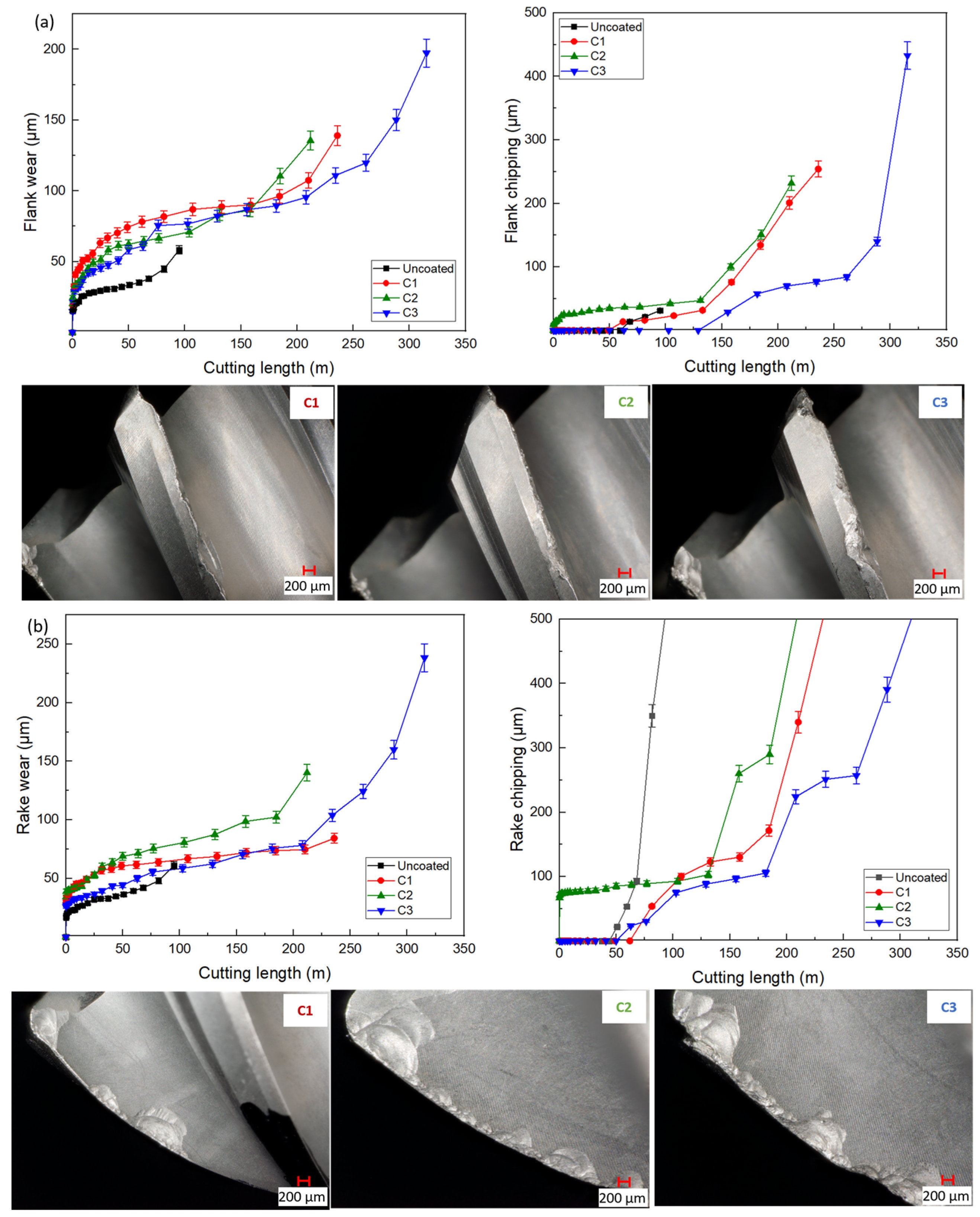
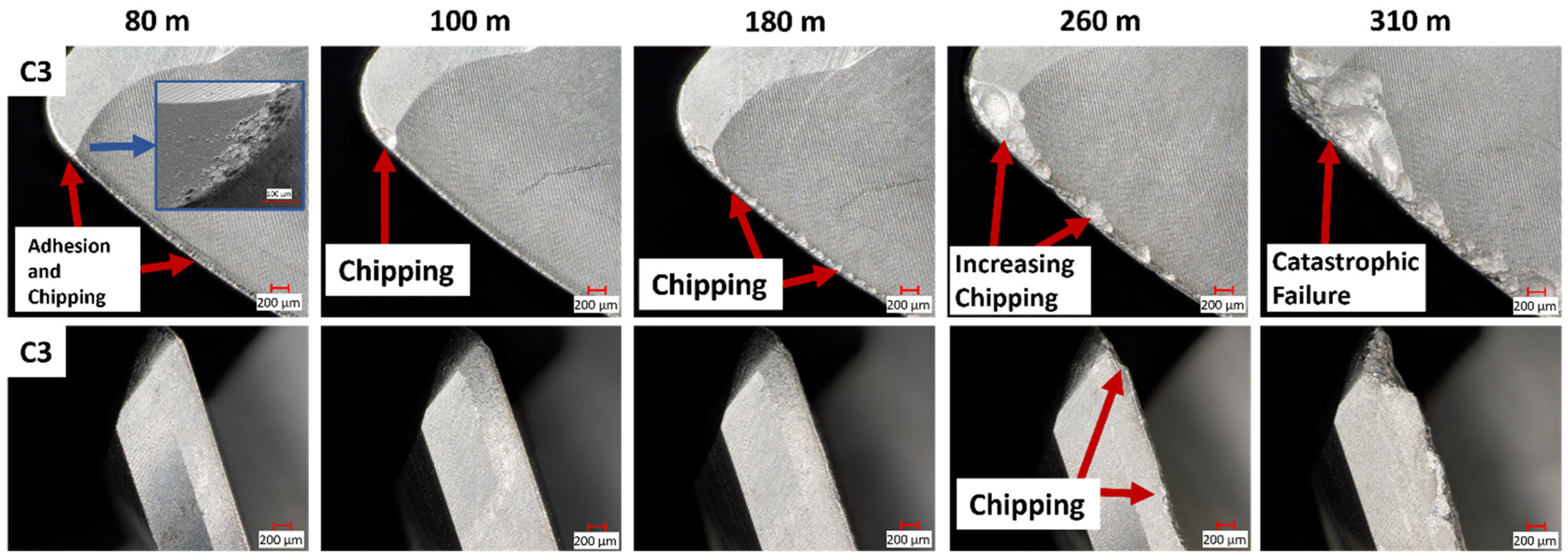
3.2. End Milling Test and Tool Wear Mechanism Analysis

An uncoated tool was used as a benchmark during the cutting tests. Figure 6 shows the tool life results, including the flank wear, flank chipping, rake wear, and rake chipping circumstances. It can be seen from Figure 6a that all the cutting tools presented gradually increasing wear on both the flank and rake faces. However, the chipping on both surfaces of the three coated tools abruptly grew, which led to tool failure (as shown in Figure 6b). Another observation was that the C3-coated tool possessed the longest tool life of over 300 m, while the C1 and C2 tools failed at around 200 m. The optical image from Figure 6 also illustrates the wear patterns on the tool flank/rake faces at the end of the tool’s life.
A few challenges could be seen during the machining of Ti6Al4V, led by its material’s high strength, low thermal conductivity, and high chemical reactivity. These characteristics resulted in significant heat generation during the cutting process, which was mostly transferred into the cutting tool. This heat caused thermal fatigue in the tool, weakening it and leading to wear. Therefore, the tool wear mechanism was considered to be a combination of abrasion, adhesion, and chipping. Abrasion occurred due to the hard particles present in the workpiece material, while adhesion was caused by the high chemical reactivity of titanium, which led to the formation of a built-up edge (BUE) on the tool. Chipping is a form of mechanical wear that results from cyclic loading and unloading during the cutting process.
Deposition of AlCrN by cathodic arc evaporation could be a better way to deposit it onto cutting tools to enhance their wear resistance. These coatings can exhibit elastic deformation during cutting, helping to dissipate energy and protect the cutting edge. However, residual stresses in these coatings can influence their performance. Residual stresses are inherent in PVD coatings due to the high-energy impact of ions on the substrate during deposition. These stresses can be tensile or compressive, and can significantly affect the coating’s mechanical properties. In particular, tensile residual stresses can lead to premature failure of the coating through processes such as cracking or delamination [46]. Looking into the results in Figure 6, it is noticeable that there was also some micro-chipping and micro-abrasion along the C3 cutting edge compared to the other two tools, which had only macro-chipping and crater areas. It was reasonably assumed that this coating could protect the cutting edge until sudden chipping caused tool failure. In terms of chipping wear, residual stresses play a crucial role [47]. Compressive residual stresses can be beneficial as they enhance the coating’s resistance to mechanical wear, which is the case of the H1957. On the other hand, for the C1 and C2, the tensile residual stresses could intensify the chipping wear by promoting crack initiation and propagation.
In order to understand the tool wear performance during the cutting test, progress wear on both the flank face and rake face was observed under a Keyence optical microscope. This helped to illustrate the wear mechanisms of the AlCrN-coated tool along with the cutting test. Figure 7 shows the wear patterns on the C3-coated tool at different cutting lengths from 80 m (initial wear stage) to 310 m (end of tool life). In the first stage, oxidation and adhesion occurred on the tool’s rake face because of the thermal effect. As Al was an active element, it easily reacted with oxygen to generate an Al-oxide layer, causing diffusion and oxidation [48,49]. With the adhesion of the workpiece material to the cutting tool, a built-up edge (BUE) on the rake face gradually appeared and consequently led to chipping that weakened the cutting edge. Uniform chipping along the whole cutting edge could be seen clearly at around 180 m, and large flake-shaped chipping coupled with crater wear was found after 260 m. The intensive chipping accelerated the overall tool wear and resulted in catastrophic failure (as shown in Figure 6). This may possibly have been a consequence of the intensive heat generation and the thermal fatigue of the tooltip, since the workpiece Ti-6Al-4V had low thermal conductivity and a high work-hardening tendency [50]. The heat generated during the cutting test was mostly transferred into the cutting tool, which caused this wear mechanism. Another reasonable correlation was the coating impact fatigue performance (see Figure 4). The C3 coating, which had the best result, exhibited elastic deformation during the cutting test and could properly dissipate energy. The combined mechanical properties and superior cutting-edge geometries of the C3 tool contributed to its improved wear performance, which protected the tool’s cutting edge for a substantially longer time.
Figure 8 shows the cutting forces during the milling process. All three coated tools experienced fluctuations in cutting forces during the tests. Among them, the C3 tool showed relatively stable cutting forces until the last pass of the milling process. This can be explained by the abrupt failure of the tool at the end of its life. Both the C2 and C1 tools, however, demonstrated diverse cutting force variations during the test. It can be seen that the C1 tool had the highest cutting force at the initial cutting stage, which then decreased rapidly, while the C2 tool showed a similar cutting force to the C3 tool at first and a sudden peak at around 80 m. The unstable cutting forces were correlated to the progress wear caused by adhesion of the workpiece material (also considered as BUE) affecting the cutting-edge geometry and friction at the tool/chip contact area [33,51]. The cutting force trend from Figure 8 also confirmed that the C3 tool had the ability to protect the cutting edge and reduce wear during the machining process.
Figure 9 shows the statistical data of the cutting tool geometry at the end of the tool’s life, which quantifies the wear status of each tool. The angles on five different tool edges were measured separately, with an accuracy of 95%, under an Alicona white light confocal microscope, and these were compared with the initial tool edge geometries before the cutting test. The C2 tool had a much higher angle difference of over 30°, while the other tools had relatively fewer deviations. Another interesting finding was that the C3 tool had more uniform edge angles even after tool failure. This, to some extent, also confirms that the C3-coated tool experienced a relatively stable wear progression, which led to a more constant milling process that was favorable for machining. The cutting-edge variation was related to the wear from BUE that caused chipping. The workpiece material adhered to the tool and then peeled off with some of the tool material, which accelerated chipping on the cutting edge. The statistical angle changes shown in Figure 9 reflects this situation. Hence, the C3 tool was deemed to have a better performance.

4. Conclusions

In this paper, the characteristics and tool performance of three different AlCrN PVD-coated end mills were studied and analyzed during the machining of a Ti-6Al-4V alloy. It was found that the C3-coated tool (with a moderate residual stress) possessed the longest tool life, almost 1.5 times longer compared to the other two coated tools. In addition, the cutting tools’ mechanical properties were considered to have a significant influence on the tool wear behavior and cutting tool life. The conclusions can be stated as follows:
(1)
The tool life test, mechanical properties analysis, and tool edge geometry measurement all confirmed that the C3-coated tool produced superior outcomes. This C3-AlCrN coating extended tool life by approximately 1.5 times compared to the other tools.
(2)
The longest tool life, obtained by the C3 tool, can be attributed to a combination of favorable mechanical properties (including H3/E2 and impact fatigue fracture) and uniform tool edge geometries (edge radius and angle). With these characteristics, the C3-coated tool was able to protect its cutting edge for a substantially longer time, which reduced the wear rate to some extent.
(3)
The major wear mechanism of AlCrN PVD-coated tools when milling Ti-6Al-4V was identified as combined abrasion and adhesion, which resulted in significant chipping on all cutting tools. The chipping wear mode predominantly present on the tool rake face was the main factor responsible for tool failure in this study.
Based on the results and analyses, AlCrN PVD-coated tools are deemed suitable for the end milling process of difficult-to-machine material Ti-6Al-4V. A good balance of mechanical properties and tool edge geometries should be addressed during cutting tool design, since these characteristics have vital impacts on tool wear performance and cutting length. Therefore, it is recommended that an AlCrN coating with moderate stress compared to a high residual stress generated from the deposition process could be applied for machining difficult-to-machine materials such as Ti-6Al-4V, especially during high-speed milling of over 100 m/min. Properties such as better resistance to plastic deformation and impact fatigue fracture are beneficial for the cutting tool wear performance and result in a superior cutting tool life. In addition, the uniform cutting edges (sharp edge radius and even angles) could be appropriately applied for the high-speed end milling of Ti-6Al-4V.

Author Contributions

Conceptualization and investigation, Q.H.; methodology, J.M.D.; validation, Q.H. and V.S.; resources, J.K.; writing—original draft preparation, Q.H.; writing—review and editing, Q.H., J.M.D., M.C.G. and M.M.M.; supervision, S.C.V.; funding acquisition, S.C.V. All authors have read and agreed to the published version of the manuscript.

Funding

This work was supported by the Natural Sciences and Engineering Research Council of Canada (NSERC) under the Canadian Network for Research and Innovation in Machining Technology (Grant number-NSERC NETGP 479639-15).

Data Availability Statement

Data are contained within the article.

Conflicts of Interest

The authors declare that the research was conducted in the absence of any commercial or financial relationships that could be construed as a potential conflict of interest.

References

  1. Nguyen, T.K. Fundamental Tool Wear Study in Turning of Ti-6Al-4V Alloy (Ti64) and Nano-Enhanced Minimum Quantity Lubrication (MQL) Milling; Michigan State University: East Lansing, MI, USA, 2015. [Google Scholar]
  2. Lagarde, Q.; Wagner, V.; Dessein, G.; Harzallah, M. Effect of Temperature on Tool Wear During Milling of Ti64. J. Manuf. Sci. Eng. 2021, 143, 071007. [Google Scholar] [CrossRef]
  3. Veiga, C.; Davim, J.P.; Loureiro, A. Properties and applications of titanium alloys: A brief review. Rev. Adv. Mater. Sci. 2012, 32, 14–34. [Google Scholar]
  4. Pramanik, A.; Islam, M.N.; Basak, A.; Littlefair, G. Machining and Tool Wear Mechanisms during Machining Titanium Alloys. In Engineering Materials and Application; Trans Tech Publications Ltd.: Bäch, Switzerland, 2013; pp. 338–343. [Google Scholar] [CrossRef]
  5. Ulutan, D.; Ozel, T. Machining induced surface integrity in titanium and nickel alloys: A review. Int. J. Mach. Tools Manuf. 2011, 51, 250–280. [Google Scholar] [CrossRef]
  6. Amin, A.K.M.N.; Ismail, A.F.; Khairusshima, M.K.N. Effectiveness of uncoated WC–Co and PCD inserts in end milling of titanium alloy—Ti–6Al–4V. J. Mater. Process. Technol. 2007, 192–193, 147–158. [Google Scholar] [CrossRef]
  7. Sahoo, P.; Singh, V.K.; Patra, K. Influences of tribological and mechanical properties of (Ti/Al)N and diamond like carbon coated tungsten carbide tool on machining and dynamic stability in micro milling of Ti6Al4V. J. Manuf. Process. 2023, 85, 915–934. [Google Scholar] [CrossRef]
  8. Rahman, M.; Wang, Z.; Wong, Y. A Review on High-Speed Machining of Titanium Alloys. JSME Int. J. Ser. C Mech. Syst. Mach. Elem. Manuf. 2006, 49, 11–20. [Google Scholar] [CrossRef]
  9. Jianxin, D.; Yousheng, L.; Wenlong, S. Diffusion wear in dry cutting of Ti–6Al–4V with WC/Co carbide tools. Wear 2008, 265, 1776–1783. [Google Scholar] [CrossRef]
  10. Hosseini, A.; Kishawy, H.A.; Hussein, H.M. Machinability of Titanium and Its Alloys. In Machinability of Advanced Materials; John Wiley & Sons, Inc.: Hoboken, NJ, USA, 2014; pp. 95–118. [Google Scholar] [CrossRef]
  11. Umbrello, D. Finite element simulation of conventional and high speed machining of Ti6Al4V alloy. J. Mater. Process. Technol. 2008, 196, 79–87. [Google Scholar] [CrossRef]
  12. Kumar, K.M.; Mathew, N.T.; Baburaj, M. Sustainable milling of Ti-6Al-4V super alloy using AlCrN and TiAlN coated tools. Mater. Today Proc. 2022, 50, 1732–1738. [Google Scholar] [CrossRef]
  13. Hosseini, A.; Kishawy, H.A. Cutting Tool Materials and Tool Wear. In Machining of Titanium Alloys; Davim, J.P., Ed.; Springer: Berlin/Heidelberg, Germany, 2014; pp. 31–56. [Google Scholar] [CrossRef]
  14. Nabhani, F. Machining of aerospace titanium alloys. Robot Comput. Integr. Manuf. 2001, 17, 99–106. [Google Scholar] [CrossRef]
  15. Soroka, O.B. Evaluation of residual stresses in PVD-coatings. Part 1. Review. Strength Mater. 2010, 42, 287–296. [Google Scholar] [CrossRef]
  16. Abadias, G.; Chason, E.; Keckes, J.; Sebastiani, M.; Thompson, G.B.; Barthel, E.; Doll, G.L.; Murray, C.E.; Stoessel, C.H.; Martinu, L. Review Article: Stress in thin films and coatings: Current status, challenges, and prospects. J. Vac. Sci. Technol. A 2018, 36, 20801. [Google Scholar] [CrossRef]
  17. Patro, S.S.; Roy, S.; Sahoo, A.K. Investigation of influence of design on residual stress at free edge of multilayer Ti/AlN coatings by PVD using FEM. Int. J. Interact. Des. Manuf. JIDeM 2023, 17, 2987–2998. [Google Scholar] [CrossRef]
  18. Liu, J.; Wang, Y.; Liu, G.; Hua, J.; Deng, X. Properties and Performance of TiAlSiN and AlCrN Monolayer and Multilayer Coatings for Turning Ti-6Al-4V. Coatings 2023, 13, 1229. [Google Scholar] [CrossRef]
  19. Mishra, S.K.; Ghosh, S.; Aravindan, S. Characterization and machining performance of laser-textured chevron shaped tools coated with AlTiN and AlCrN coatings. Surf. Coat. Technol. 2018, 334, 344–356. [Google Scholar] [CrossRef]
  20. Reiter, A.E.; Derflinger, V.H.; Hanselmann, B.; Bachmann, T.; Sartory, B. Investigation of the properties of Al1–xCrxN coatings prepared by cathodic arc evaporation. Surf. Coat. Technol. 2005, 200, 2114–2122. [Google Scholar] [CrossRef]
  21. Mo, J.L.; Zhu, M.H.; Leyland, A. Matthews, Impact wear and abrasion resistance of CrN, AlCrN and AlTiN PVD coatings. Surf. Coat. Technol. 2013, 215, 170–177. [Google Scholar] [CrossRef]
  22. Feng, Y.; Zhang, L.; Ke, R.; Wan, Q.; Wang, Z.; Lu, Z. Thermal stability and oxidation behavior of AlTiN, AlCrN and AlCrSiWN coatings. Int. J. Refract. Metals Hard Mater. 2014, 43, 241–249. [Google Scholar] [CrossRef]
  23. Zhang, J.; Ling, L.; Luo, D.; Deng, C.; Huang, X.; Tao, G.; Cao, H. Cutting performance and surface quality of Ti-6Al-4V by longitudinal ultrasonic vibration-assisted high-speed dry milling with coated carbide tools. Int. J. Adv. Manuf. Technol. 2023, 126, 5583–5596. [Google Scholar] [CrossRef]
  24. Kim, D.; Swan, S.R.; He, B.; Khominich, V.; Bell, E.; Lee, S.-W.; Kim, T.-G. A study on the machinability of advanced arc PVD AlCrN-coated tungsten carbide tools in drilling of CFRP/titanium alloy stacks. Carbon Lett. 2021, 31, 497–507. [Google Scholar] [CrossRef]
  25. ISO 19252:2008; Plastics—Determination of Scratch Properties, Technical Committee ISO/TC 61, Plastics, Subcommittee SC 2, Mechanical Properties. ISO: Geneva, Switzerland, 2008.
  26. ISO 8688-2:1989; Tool Life Testing in Milling—Part 2: End Milling. ISO: Geneva, Switzerland, 1989.
  27. Panjan, P.; Cekada, M. Growth defects in PVD hard coatings Growth defects in PVD hard coatings. Vaccum 2009, 84, 209–214. [Google Scholar] [CrossRef]
  28. Polcar, T.; Cavaleiro, A. High temperature properties of CrAlN, CrAlSiN and AlCrSiN coatings—Structure and oxidation. Mater. Chem. Phys. 2011, 129, 195–201. [Google Scholar] [CrossRef]
  29. Kumar, T.S.; Prabu, S.B.; Manivasagam, G.; Padmanabhan, K.A. Comparison of TiAlN, AlCrN, and AlCrN/TiAlN coatings for cutting-tool applications. Int. J. Miner. Metall. Mater. 2014, 21, 796–805. [Google Scholar] [CrossRef]
  30. Khatibi, A.; Sjölen, J.; Greczynski, G.; Jensen, J.; Eklund, P.; Hultman, L. Structural and mechanical properties of Cr–Al–O–N thin films grown by cathodic arc deposition. Acta Mater. 2012, 60, 6494–6507. [Google Scholar] [CrossRef]
  31. Kumar, T.S.; Prabu, S.B.; Manivasagam, G. Metallurgical Characteristics of TiAlN/AlCrN Coating Synthesized by the PVD Process on a Cutting Insert. J. Mater. Eng. Perform. 2014, 23, 2877–2884. [Google Scholar] [CrossRef]
  32. Barber, Z.H. The Structure of Vapor-Deposited Materials. In Reference Module in Materials Science and Materials Engineering; Elsevier: Amsterdam, The Netherlands, 2016. [Google Scholar] [CrossRef]
  33. He, Q.; Paiva, J.M.; Kohlscheen, J.; Beake, B.D.; Veldhuis, S.C. Study of wear performance and tribological characterization of AlTiN PVD coatings with different Al/Ti ratios during ultra-high speed turning of stainless steel 304. Int. J. Refract. Metals Hard Mater. 2021, 96, 105488. [Google Scholar] [CrossRef]
  34. Lan, R.; Wang, C.; Ma, Z.; Lu, G.; Wang, P.; Han, J. Effects of arc current and bias voltage on properties of AlCrN coatings by arc ion plating with large target. Mater. Res. Express 2019, 6, 116457. [Google Scholar] [CrossRef]
  35. He, Q.; Paiva, J.M.; Kohlscheen, J.; Beake, B.D.; Veldhuis, S.C. An integrative approach to coating/carbide substrate design of CVD and PVD coated cutting tools during the machining of austenitic stainless steel. Ceram. Int. 2020, 46, 5149–5158. [Google Scholar] [CrossRef]
  36. ASTM C1624-22; Standard Test Method for Adhesion Strength and Mechanical Failure Modes of Ceramic Coatings by Quantitative Single Point Scratch Testing. ASTM International: West Conshohocken, PA, USA, 2022.
  37. Gilewicz, A.; Kuznetsova, T.; Aizikovich, S.; Lapitskaya, V.; Khabarava, A.; Nikolaev, A.; Warcholinski, B. Comparative Investigations of AlCrN Coatings Formed by Cathodic Arc Evaporation under Different Nitrogen Pressure or Arc Current. Materials 2021, 14, 304. [Google Scholar] [CrossRef]
  38. Evans, A.G.; Hutchinson, J.W. The mechanics of coating delamination in thermal gradients. Surf. Coat. Technol. 2007, 201, 7905–7916. [Google Scholar] [CrossRef]
  39. Li, T.; Li, M.; Zhou, Y. Phase segregation and its effect on the adhesion of Cr–Al–N coatings on K38G alloy prepared by magnetron sputtering method. Surf. Coat. Technol. 2007, 201, 7692–7698. [Google Scholar] [CrossRef]
  40. Beake, B.D.; Smith, J.F.; Gray, A.; Fox-Rabinovich, G.S.; Veldhuis, S.C.; Endrino, J.L. Investigating the correlation between nano-impact fracture resistance and hardness/modulus ratio from nanoindentation at 25–500 °C and the fracture resistance and lifetime of cutting tools with Ti1−xAlxN (x = 0.5 and 0.67) PVD coatings in milling operations. Surf. Coat. Technol. 2007, 201, 4585–4593. [Google Scholar] [CrossRef]
  41. Beake, B.D.; Smith, J.F. Nano-impact testing—An effective tool for assessing the resistance of advanced wear-resistant coatings to fatigue failure and delamination. Surf. Coat. Technol. 2004, 188–189, 594–598. [Google Scholar] [CrossRef]
  42. Beake, B.D.; Ning, L.; Gey, C.; Veldhuis, S.C.; Kornberg, A.B.; Weaver, A.; Khanna, M.; Fox-Rabinovich, G.S. Wear performance of different PVD coatings during hard wet end milling of H13 tool steel. Surf. Coat. Technol. 2015, 279, 118–125. [Google Scholar] [CrossRef]
  43. Amirnasiri, A.; Haghshenas, M.S.; Parvin, N. Damaging of cemented carbide end mill with different grain sizes: Experimental and simulation. Rare Met. 2021, 40, 671–678. [Google Scholar] [CrossRef]
  44. García, J.; Ciprés, V.C.; Blomqvist, A.; Kaplan, B. Cemented carbide microstructures: A review. Int. J. Refract. Metals Hard Mater. 2019, 80, 40–68. [Google Scholar] [CrossRef]
  45. ISO 4499-2:2008; Hardmetals—Metallographic Determination of Microstructure—Part 2: Measurement of WC Grain Size. ISO: Geneva, Switzerland, 2008.
  46. Teppernegg, T.; Czettl, C.; Michotte, C.; Mitterer, C. Arc evaporated Ti-Al-N/Cr-Al-N multilayer coating systems for cutting applications. Int. J. Refract. Metals Hard Mater. 2018, 72, 83–88. [Google Scholar] [CrossRef]
  47. Gilewicz, A.; Jedrzejewski, R.; Myslinski, P.; Warcholinski, B. Structure, Morphology, and Mechanical Properties of AlCrN Coatings Deposited by Cathodic Arc Evaporation. J. Mater. Eng. Perform. 2019, 28, 1522–1531. [Google Scholar] [CrossRef]
  48. Kohlscheen, J.; Bareiss, C. Effect of Hexagonal Phase Content on Wear Behaviour of AlTiN Arc PVD Coatings. Coatings 2018, 8, 72. [Google Scholar] [CrossRef]
  49. He, Q.; DePaiva, J.M.; Kohlscheen, J.; Veldhuis, S.C. Analysis of the performance of PVD AlTiN coating with five different Al/Ti ratios during the high-speed turning of stainless steel 304 under dry and wet cooling conditions. Wear 2022, 492–493, 204213. [Google Scholar] [CrossRef]
  50. Hedberg, G.K.; Shin, Y.C.; Xu, L. Laser-assisted milling of Ti-6Al-4V with the consideration of surface integrity. Int. J. Adv. Manuf. Technol. 2015, 79, 1645–1658. [Google Scholar] [CrossRef]
  51. Sivaraman, V.; Sankaran, S.; Vijayaraghavan, L. The Effect of Cutting Parameters on Cutting Force during Turning Multiphase Microalloyed Steel. Procedia CIRP 2012, 4, 157–160. [Google Scholar] [CrossRef]
Figure 1. AlCrN coating surface morphology: (ac) optical image showing coating defects; (df) SEM/EDS image identifying coating composition and porosity.
Jmmp 08 00068 g001
Figure 2. SEM/EDS of coating cross-section.
Jmmp 08 00068 g002
Figure 3. Optical image of scratch tracks on AlCrN coatings.
Jmmp 08 00068 g003
Figure 4. Impact fatigue test result of three coatings.
Jmmp 08 00068 g004
Figure 5. Cutting edge geometry measurement of three end mill tools.
Jmmp 08 00068 g005
Figure 6. Cutting tool life curve and optical image of failed AlCrN-coated tools: (a) flank face, and (b) rake face.
Jmmp 08 00068 g006
Figure 7. Progress wear mechanisms of C3-coated tool.
Jmmp 08 00068 g007
Figure 8. Cutting forces curve of three AlCrN-coated tools during the milling process.
Jmmp 08 00068 g008
Figure 9. The deviation of cutting-edge geometry after tool failure.
Jmmp 08 00068 g009
Table 1. Deposition parameters for AlCrN coatings.
CoatingsDesignationI/ARing (A)Bias 1 (V)t1 (min)Bias 2 (V)t2 (min)
C1High stress1500.5100515090
C2Standard403015060
C3Moderate stress1009000
Table 2. End milling parameters with machine set-up for cutting tool life tests.
Cutting Speed (m/min)100Jmmp 08 00068 i001
Feed rate (mm/tooth)0.05
Number of teeth5
Depth of cut (mm)5
Radial depth of cut (mm)1
Coolant11% Flood
Tool holderHSK-100A
Table 3. Chemical composition and mechanical properties of Ti-6Al-4V alloy.
Element (%)AlVFeCNOOthersTi
6.33.860.20.0180.0030.1810.09Balance
Hardness (GPa)Tensile strength (MPa)Yield strength (MPa)
5.8895828
Table 4. Coatings’ micromechanical properties and surface characteristics.
CoatingsC1C2C3
Hardness (GPa)39.2 ± 3.038.3 ± 3.437.6 ± 3.6
Reduced elastic modulus (GPa)393 ± 22380 ± 30373 ± 29
H/E0.1000.1010.101
H3/E20.3900.3890.382
Plasticity Index, PI0.3500.3500.350
Lc1 (N)20.7 ± 1.324.9 ± 1.817.7 ± 0.3
Lc2 (N)32.6 ± 0.936.8 ± 1.229.6 ± 0.9
Lc3 (N)55.2 ± 0.959.5 ± 0.955.6 ± 0.1
Surface average, Sa (μm)0.25 ± 0.010.24 ± 0.010.22 ± 0.01
Disclaimer/Publisher’s Note: The statements, opinions and data contained in all publications are solely those of the individual author(s) and contributor(s) and not of MDPI and/or the editor(s). MDPI and/or the editor(s) disclaim responsibility for any injury to people or property resulting from any ideas, methods, instructions or products referred to in the content.

